EP2097034B1 - Druckempfindlicher und leitfähiger verbundkontaktsensor - Google Patents
Druckempfindlicher und leitfähiger verbundkontaktsensor Download PDFInfo
- Publication number
- EP2097034B1 EP2097034B1 EP07871747.7A EP07871747A EP2097034B1 EP 2097034 B1 EP2097034 B1 EP 2097034B1 EP 07871747 A EP07871747 A EP 07871747A EP 2097034 B1 EP2097034 B1 EP 2097034B1
- Authority
- EP
- European Patent Office
- Prior art keywords
- pscc
- contact
- sensor
- conductive
- pressure
- Prior art date
- Legal status (The legal status is an assumption and is not a legal conclusion. Google has not performed a legal analysis and makes no representation as to the accuracy of the status listed.)
- Not-in-force
Links
- 239000002131 composite material Substances 0.000 title claims description 57
- 238000005259 measurement Methods 0.000 claims description 57
- 239000004020 conductor Substances 0.000 description 60
- 239000000463 material Substances 0.000 description 21
- 239000000758 substrate Substances 0.000 description 19
- 230000005641 tunneling Effects 0.000 description 17
- 238000000034 method Methods 0.000 description 13
- 238000012544 monitoring process Methods 0.000 description 10
- 239000012212 insulator Substances 0.000 description 8
- 229920001940 conductive polymer Polymers 0.000 description 6
- BASFCYQUMIYNBI-UHFFFAOYSA-N platinum Chemical compound [Pt] BASFCYQUMIYNBI-UHFFFAOYSA-N 0.000 description 6
- BQCADISMDOOEFD-UHFFFAOYSA-N Silver Chemical compound [Ag] BQCADISMDOOEFD-UHFFFAOYSA-N 0.000 description 5
- 230000008859 change Effects 0.000 description 5
- 239000011248 coating agent Substances 0.000 description 5
- 238000000576 coating method Methods 0.000 description 5
- 238000004519 manufacturing process Methods 0.000 description 5
- 229910052709 silver Inorganic materials 0.000 description 5
- 239000004332 silver Substances 0.000 description 5
- PXHVJJICTQNCMI-UHFFFAOYSA-N Nickel Chemical compound [Ni] PXHVJJICTQNCMI-UHFFFAOYSA-N 0.000 description 4
- 239000000560 biocompatible material Substances 0.000 description 4
- 229910001000 nickel titanium Inorganic materials 0.000 description 4
- 229920000642 polymer Polymers 0.000 description 4
- 238000011282 treatment Methods 0.000 description 4
- RYGMFSIKBFXOCR-UHFFFAOYSA-N Copper Chemical compound [Cu] RYGMFSIKBFXOCR-UHFFFAOYSA-N 0.000 description 3
- 238000002679 ablation Methods 0.000 description 3
- 208000010247 contact dermatitis Diseases 0.000 description 3
- 229910052802 copper Inorganic materials 0.000 description 3
- 239000010949 copper Substances 0.000 description 3
- PCHJSUWPFVWCPO-UHFFFAOYSA-N gold Chemical compound [Au] PCHJSUWPFVWCPO-UHFFFAOYSA-N 0.000 description 3
- 229910052737 gold Inorganic materials 0.000 description 3
- 239000010931 gold Substances 0.000 description 3
- 239000000203 mixture Substances 0.000 description 3
- 229910052697 platinum Inorganic materials 0.000 description 3
- 239000000843 powder Substances 0.000 description 3
- 210000003492 pulmonary vein Anatomy 0.000 description 3
- 238000007674 radiofrequency ablation Methods 0.000 description 3
- 229920002379 silicone rubber Polymers 0.000 description 3
- OKTJSMMVPCPJKN-UHFFFAOYSA-N Carbon Chemical compound [C] OKTJSMMVPCPJKN-UHFFFAOYSA-N 0.000 description 2
- 206010018910 Haemolysis Diseases 0.000 description 2
- XEEYBQQBJWHFJM-UHFFFAOYSA-N Iron Chemical compound [Fe] XEEYBQQBJWHFJM-UHFFFAOYSA-N 0.000 description 2
- KDLHZDBZIXYQEI-UHFFFAOYSA-N Palladium Chemical compound [Pd] KDLHZDBZIXYQEI-UHFFFAOYSA-N 0.000 description 2
- RTAQQCXQSZGOHL-UHFFFAOYSA-N Titanium Chemical compound [Ti] RTAQQCXQSZGOHL-UHFFFAOYSA-N 0.000 description 2
- HZEWFHLRYVTOIW-UHFFFAOYSA-N [Ti].[Ni] Chemical compound [Ti].[Ni] HZEWFHLRYVTOIW-UHFFFAOYSA-N 0.000 description 2
- 229910045601 alloy Inorganic materials 0.000 description 2
- 239000000956 alloy Substances 0.000 description 2
- 230000001746 atrial effect Effects 0.000 description 2
- 230000008901 benefit Effects 0.000 description 2
- 239000008280 blood Substances 0.000 description 2
- 210000004369 blood Anatomy 0.000 description 2
- 238000010276 construction Methods 0.000 description 2
- 230000000875 corresponding effect Effects 0.000 description 2
- 230000008588 hemolysis Effects 0.000 description 2
- 238000002513 implantation Methods 0.000 description 2
- 238000002347 injection Methods 0.000 description 2
- 239000007924 injection Substances 0.000 description 2
- 229910052741 iridium Inorganic materials 0.000 description 2
- GKOZUEZYRPOHIO-UHFFFAOYSA-N iridium atom Chemical compound [Ir] GKOZUEZYRPOHIO-UHFFFAOYSA-N 0.000 description 2
- 229910052751 metal Inorganic materials 0.000 description 2
- 239000002184 metal Substances 0.000 description 2
- 229910052759 nickel Inorganic materials 0.000 description 2
- HLXZNVUGXRDIFK-UHFFFAOYSA-N nickel titanium Chemical compound [Ti].[Ti].[Ti].[Ti].[Ti].[Ti].[Ti].[Ti].[Ti].[Ti].[Ti].[Ni].[Ni].[Ni].[Ni].[Ni].[Ni].[Ni].[Ni].[Ni].[Ni].[Ni].[Ni].[Ni].[Ni] HLXZNVUGXRDIFK-UHFFFAOYSA-N 0.000 description 2
- 229920001296 polysiloxane Polymers 0.000 description 2
- 230000001681 protective effect Effects 0.000 description 2
- 239000004945 silicone rubber Substances 0.000 description 2
- 231100000057 systemic toxicity Toxicity 0.000 description 2
- 229910052715 tantalum Inorganic materials 0.000 description 2
- GUVRBAGPIYLISA-UHFFFAOYSA-N tantalum atom Chemical compound [Ta] GUVRBAGPIYLISA-UHFFFAOYSA-N 0.000 description 2
- 229910052719 titanium Inorganic materials 0.000 description 2
- 239000010936 titanium Substances 0.000 description 2
- 230000002861 ventricular Effects 0.000 description 2
- ZOXJGFHDIHLPTG-UHFFFAOYSA-N Boron Chemical compound [B] ZOXJGFHDIHLPTG-UHFFFAOYSA-N 0.000 description 1
- VYZAMTAEIAYCRO-UHFFFAOYSA-N Chromium Chemical compound [Cr] VYZAMTAEIAYCRO-UHFFFAOYSA-N 0.000 description 1
- ZOKXTWBITQBERF-UHFFFAOYSA-N Molybdenum Chemical compound [Mo] ZOKXTWBITQBERF-UHFFFAOYSA-N 0.000 description 1
- KJTLSVCANCCWHF-UHFFFAOYSA-N Ruthenium Chemical compound [Ru] KJTLSVCANCCWHF-UHFFFAOYSA-N 0.000 description 1
- 208000007536 Thrombosis Diseases 0.000 description 1
- ATJFFYVFTNAWJD-UHFFFAOYSA-N Tin Chemical compound [Sn] ATJFFYVFTNAWJD-UHFFFAOYSA-N 0.000 description 1
- HCHKCACWOHOZIP-UHFFFAOYSA-N Zinc Chemical compound [Zn] HCHKCACWOHOZIP-UHFFFAOYSA-N 0.000 description 1
- QCWXUUIWCKQGHC-UHFFFAOYSA-N Zirconium Chemical compound [Zr] QCWXUUIWCKQGHC-UHFFFAOYSA-N 0.000 description 1
- 229910052768 actinide Inorganic materials 0.000 description 1
- 150000001255 actinides Chemical class 0.000 description 1
- 230000004075 alteration Effects 0.000 description 1
- 229910052782 aluminium Inorganic materials 0.000 description 1
- XAGFODPZIPBFFR-UHFFFAOYSA-N aluminium Chemical compound [Al] XAGFODPZIPBFFR-UHFFFAOYSA-N 0.000 description 1
- 229910052787 antimony Inorganic materials 0.000 description 1
- WATWJIUSRGPENY-UHFFFAOYSA-N antimony atom Chemical compound [Sb] WATWJIUSRGPENY-UHFFFAOYSA-N 0.000 description 1
- 229910052785 arsenic Inorganic materials 0.000 description 1
- RQNWIZPPADIBDY-UHFFFAOYSA-N arsenic atom Chemical compound [As] RQNWIZPPADIBDY-UHFFFAOYSA-N 0.000 description 1
- 229910052790 beryllium Inorganic materials 0.000 description 1
- ATBAMAFKBVZNFJ-UHFFFAOYSA-N beryllium atom Chemical compound [Be] ATBAMAFKBVZNFJ-UHFFFAOYSA-N 0.000 description 1
- 230000015572 biosynthetic process Effects 0.000 description 1
- 229910052797 bismuth Inorganic materials 0.000 description 1
- JCXGWMGPZLAOME-UHFFFAOYSA-N bismuth atom Chemical compound [Bi] JCXGWMGPZLAOME-UHFFFAOYSA-N 0.000 description 1
- 210000004204 blood vessel Anatomy 0.000 description 1
- 229910052796 boron Inorganic materials 0.000 description 1
- 229910052793 cadmium Inorganic materials 0.000 description 1
- BDOSMKKIYDKNTQ-UHFFFAOYSA-N cadmium atom Chemical compound [Cd] BDOSMKKIYDKNTQ-UHFFFAOYSA-N 0.000 description 1
- 229910052799 carbon Inorganic materials 0.000 description 1
- 210000005242 cardiac chamber Anatomy 0.000 description 1
- 239000003795 chemical substances by application Substances 0.000 description 1
- 229910052804 chromium Inorganic materials 0.000 description 1
- 239000011651 chromium Substances 0.000 description 1
- 229910017052 cobalt Inorganic materials 0.000 description 1
- 239000010941 cobalt Substances 0.000 description 1
- GUTLYIVDDKVIGB-UHFFFAOYSA-N cobalt atom Chemical compound [Co] GUTLYIVDDKVIGB-UHFFFAOYSA-N 0.000 description 1
- 230000006835 compression Effects 0.000 description 1
- 238000007906 compression Methods 0.000 description 1
- 230000002596 correlated effect Effects 0.000 description 1
- 230000007423 decrease Effects 0.000 description 1
- 238000013461 design Methods 0.000 description 1
- 230000000694 effects Effects 0.000 description 1
- 229920001971 elastomer Polymers 0.000 description 1
- 239000000806 elastomer Substances 0.000 description 1
- 239000004744 fabric Substances 0.000 description 1
- 239000000835 fiber Substances 0.000 description 1
- -1 for example Substances 0.000 description 1
- 229910052732 germanium Inorganic materials 0.000 description 1
- GNPVGFCGXDBREM-UHFFFAOYSA-N germanium atom Chemical compound [Ge] GNPVGFCGXDBREM-UHFFFAOYSA-N 0.000 description 1
- 229910002804 graphite Inorganic materials 0.000 description 1
- 239000010439 graphite Substances 0.000 description 1
- 229910052735 hafnium Inorganic materials 0.000 description 1
- VBJZVLUMGGDVMO-UHFFFAOYSA-N hafnium atom Chemical compound [Hf] VBJZVLUMGGDVMO-UHFFFAOYSA-N 0.000 description 1
- 229910052742 iron Inorganic materials 0.000 description 1
- 229910052747 lanthanoid Inorganic materials 0.000 description 1
- 150000002602 lanthanoids Chemical class 0.000 description 1
- 239000011133 lead Substances 0.000 description 1
- 230000003902 lesion Effects 0.000 description 1
- WPBNNNQJVZRUHP-UHFFFAOYSA-L manganese(2+);methyl n-[[2-(methoxycarbonylcarbamothioylamino)phenyl]carbamothioyl]carbamate;n-[2-(sulfidocarbothioylamino)ethyl]carbamodithioate Chemical compound [Mn+2].[S-]C(=S)NCCNC([S-])=S.COC(=O)NC(=S)NC1=CC=CC=C1NC(=S)NC(=O)OC WPBNNNQJVZRUHP-UHFFFAOYSA-L 0.000 description 1
- 229910044991 metal oxide Inorganic materials 0.000 description 1
- 150000004706 metal oxides Chemical class 0.000 description 1
- 150000002739 metals Chemical class 0.000 description 1
- 230000000116 mitigating effect Effects 0.000 description 1
- 229910052750 molybdenum Inorganic materials 0.000 description 1
- 239000011733 molybdenum Substances 0.000 description 1
- 210000004165 myocardium Anatomy 0.000 description 1
- 229910052758 niobium Inorganic materials 0.000 description 1
- 239000010955 niobium Substances 0.000 description 1
- GUCVJGMIXFAOAE-UHFFFAOYSA-N niobium atom Chemical compound [Nb] GUCVJGMIXFAOAE-UHFFFAOYSA-N 0.000 description 1
- 239000000615 nonconductor Substances 0.000 description 1
- 229910052762 osmium Inorganic materials 0.000 description 1
- SYQBFIAQOQZEGI-UHFFFAOYSA-N osmium atom Chemical compound [Os] SYQBFIAQOQZEGI-UHFFFAOYSA-N 0.000 description 1
- 229910052763 palladium Inorganic materials 0.000 description 1
- 239000002245 particle Substances 0.000 description 1
- 239000006187 pill Substances 0.000 description 1
- 229920002635 polyurethane Polymers 0.000 description 1
- 239000004814 polyurethane Substances 0.000 description 1
- 238000003825 pressing Methods 0.000 description 1
- 230000008569 process Effects 0.000 description 1
- 230000004044 response Effects 0.000 description 1
- 230000002441 reversible effect Effects 0.000 description 1
- 229910052702 rhenium Inorganic materials 0.000 description 1
- WUAPFZMCVAUBPE-UHFFFAOYSA-N rhenium atom Chemical compound [Re] WUAPFZMCVAUBPE-UHFFFAOYSA-N 0.000 description 1
- 229910052703 rhodium Inorganic materials 0.000 description 1
- 239000010948 rhodium Substances 0.000 description 1
- MHOVAHRLVXNVSD-UHFFFAOYSA-N rhodium atom Chemical compound [Rh] MHOVAHRLVXNVSD-UHFFFAOYSA-N 0.000 description 1
- 229910052707 ruthenium Inorganic materials 0.000 description 1
- 229910052706 scandium Inorganic materials 0.000 description 1
- SIXSYDAISGFNSX-UHFFFAOYSA-N scandium atom Chemical compound [Sc] SIXSYDAISGFNSX-UHFFFAOYSA-N 0.000 description 1
- 230000035945 sensitivity Effects 0.000 description 1
- 229940024463 silicone emollient and protective product Drugs 0.000 description 1
- 238000001228 spectrum Methods 0.000 description 1
- 239000010935 stainless steel Substances 0.000 description 1
- 229910001220 stainless steel Inorganic materials 0.000 description 1
- 229910052713 technetium Inorganic materials 0.000 description 1
- GKLVYJBZJHMRIY-UHFFFAOYSA-N technetium atom Chemical compound [Tc] GKLVYJBZJHMRIY-UHFFFAOYSA-N 0.000 description 1
- 229910052718 tin Inorganic materials 0.000 description 1
- 239000011135 tin Substances 0.000 description 1
- 238000012546 transfer Methods 0.000 description 1
- 230000009466 transformation Effects 0.000 description 1
- 230000007704 transition Effects 0.000 description 1
- WFKWXMTUELFFGS-UHFFFAOYSA-N tungsten Chemical compound [W] WFKWXMTUELFFGS-UHFFFAOYSA-N 0.000 description 1
- 229910052721 tungsten Inorganic materials 0.000 description 1
- 239000010937 tungsten Substances 0.000 description 1
- 229910052720 vanadium Inorganic materials 0.000 description 1
- LEONUFNNVUYDNQ-UHFFFAOYSA-N vanadium atom Chemical compound [V] LEONUFNNVUYDNQ-UHFFFAOYSA-N 0.000 description 1
- 229910052725 zinc Inorganic materials 0.000 description 1
- 239000011701 zinc Substances 0.000 description 1
- 229910052726 zirconium Inorganic materials 0.000 description 1
Images


Classifications
-
- A—HUMAN NECESSITIES
- A61—MEDICAL OR VETERINARY SCIENCE; HYGIENE
- A61B—DIAGNOSIS; SURGERY; IDENTIFICATION
- A61B18/00—Surgical instruments, devices or methods for transferring non-mechanical forms of energy to or from the body
- A61B18/04—Surgical instruments, devices or methods for transferring non-mechanical forms of energy to or from the body by heating
- A61B18/12—Surgical instruments, devices or methods for transferring non-mechanical forms of energy to or from the body by heating by passing a current through the tissue to be heated, e.g. high-frequency current
- A61B18/14—Probes or electrodes therefor
- A61B18/1492—Probes or electrodes therefor having a flexible, catheter-like structure, e.g. for heart ablation
-
- A—HUMAN NECESSITIES
- A61—MEDICAL OR VETERINARY SCIENCE; HYGIENE
- A61B—DIAGNOSIS; SURGERY; IDENTIFICATION
- A61B5/00—Measuring for diagnostic purposes; Identification of persons
- A61B5/68—Arrangements of detecting, measuring or recording means, e.g. sensors, in relation to patient
- A61B5/6846—Arrangements of detecting, measuring or recording means, e.g. sensors, in relation to patient specially adapted to be brought in contact with an internal body part, i.e. invasive
- A61B5/6885—Monitoring or controlling sensor contact pressure
-
- A—HUMAN NECESSITIES
- A61—MEDICAL OR VETERINARY SCIENCE; HYGIENE
- A61M—DEVICES FOR INTRODUCING MEDIA INTO, OR ONTO, THE BODY; DEVICES FOR TRANSDUCING BODY MEDIA OR FOR TAKING MEDIA FROM THE BODY; DEVICES FOR PRODUCING OR ENDING SLEEP OR STUPOR
- A61M25/00—Catheters; Hollow probes
-
- G—PHYSICS
- G01—MEASURING; TESTING
- G01L—MEASURING FORCE, STRESS, TORQUE, WORK, MECHANICAL POWER, MECHANICAL EFFICIENCY, OR FLUID PRESSURE
- G01L1/00—Measuring force or stress, in general
- G01L1/20—Measuring force or stress, in general by measuring variations in ohmic resistance of solid materials or of electrically-conductive fluids; by making use of electrokinetic cells, i.e. liquid-containing cells wherein an electrical potential is produced or varied upon the application of stress
-
- A—HUMAN NECESSITIES
- A61—MEDICAL OR VETERINARY SCIENCE; HYGIENE
- A61B—DIAGNOSIS; SURGERY; IDENTIFICATION
- A61B18/00—Surgical instruments, devices or methods for transferring non-mechanical forms of energy to or from the body
- A61B2018/00053—Mechanical features of the instrument of device
- A61B2018/00059—Material properties
- A61B2018/00071—Electrical conductivity
- A61B2018/00083—Electrical conductivity low, i.e. electrically insulating
-
- A—HUMAN NECESSITIES
- A61—MEDICAL OR VETERINARY SCIENCE; HYGIENE
- A61B—DIAGNOSIS; SURGERY; IDENTIFICATION
- A61B18/00—Surgical instruments, devices or methods for transferring non-mechanical forms of energy to or from the body
- A61B2018/00571—Surgical instruments, devices or methods for transferring non-mechanical forms of energy to or from the body for achieving a particular surgical effect
- A61B2018/00577—Ablation
-
- A—HUMAN NECESSITIES
- A61—MEDICAL OR VETERINARY SCIENCE; HYGIENE
- A61B—DIAGNOSIS; SURGERY; IDENTIFICATION
- A61B18/00—Surgical instruments, devices or methods for transferring non-mechanical forms of energy to or from the body
- A61B2018/00636—Sensing and controlling the application of energy
- A61B2018/00773—Sensed parameters
- A61B2018/00875—Resistance or impedance
-
- A—HUMAN NECESSITIES
- A61—MEDICAL OR VETERINARY SCIENCE; HYGIENE
- A61B—DIAGNOSIS; SURGERY; IDENTIFICATION
- A61B18/00—Surgical instruments, devices or methods for transferring non-mechanical forms of energy to or from the body
- A61B2018/00988—Means for storing information, e.g. calibration constants, or for preventing excessive use, e.g. usage, service life counter
-
- A—HUMAN NECESSITIES
- A61—MEDICAL OR VETERINARY SCIENCE; HYGIENE
- A61B—DIAGNOSIS; SURGERY; IDENTIFICATION
- A61B90/00—Instruments, implements or accessories specially adapted for surgery or diagnosis and not covered by any of the groups A61B1/00 - A61B50/00, e.g. for luxation treatment or for protecting wound edges
- A61B90/06—Measuring instruments not otherwise provided for
- A61B2090/064—Measuring instruments not otherwise provided for for measuring force, pressure or mechanical tension
- A61B2090/065—Measuring instruments not otherwise provided for for measuring force, pressure or mechanical tension for measuring contact or contact pressure
-
- A—HUMAN NECESSITIES
- A61—MEDICAL OR VETERINARY SCIENCE; HYGIENE
- A61M—DEVICES FOR INTRODUCING MEDIA INTO, OR ONTO, THE BODY; DEVICES FOR TRANSDUCING BODY MEDIA OR FOR TAKING MEDIA FROM THE BODY; DEVICES FOR PRODUCING OR ENDING SLEEP OR STUPOR
- A61M25/00—Catheters; Hollow probes
- A61M2025/0001—Catheters; Hollow probes for pressure measurement
- A61M2025/0002—Catheters; Hollow probes for pressure measurement with a pressure sensor at the distal end
Definitions
- the present invention pertains generally to an electrophysiological device and method for providing energy to biological tissue and, more particularly, to a contact sensor that is capable of being using with an ablation apparatus to provide greater contact sensitivity.
- Sensing devices including tissue sensing devices, have heretofore been provided, but not pressure sensitive conductive composite ("PSCC”) based sensors (including, for example, quantum tunneling composites (“QTC”) and other pressure-sensitive, conductive polymers).
- PSCC pressure sensitive conductive composite
- QTC quantum tunneling composites
- US 6221023 B1 relates to a sensor mounted on a distal end of an intra-corporeal catheter which detects pressure applied thereto by using a mushroom-like projection which is bend by a pressure applied.
- US 2006/137464 A1 generally relates to sensors and methods for sensing and more particularly for a force sensor for measuring a strain. Rajshree Mootanah, Dan L. Bader: "Pressure Sensors", 14 April 2006 (2006-04-14), Retrieved from the Internet: URL:http://onlinelibrary.wiley.com/doi/10.1002/9780471740360 .
- ebs0958/full discloses several pressure sensors.
- WO 97/18754 discloses a catheter assembly for assessing contact between the catheter assembly and tissue, said assembly comprising a catheter shaft, a flexible inner conductive core, a pressure sensitive conductive composite member which is mechanically and electrically coupled to the flexible inner conductive core, a measurement terminal and a measurement device adapted to measure changes in resistance of the pressure sensitive conductive member.
- a catheter assembly for assessing contact between the catheter assembly and tissue, which assembly includes a catheter shaft and a pressure sensitive conductive composite member whose electrical resistance varies with pressure applied to the catheter assembly.
- the assembly also includes at least one measurement terminal to permit the measurement of changes in resistance of the pressure sensitive conductive composite member.
- the assembly may optionally include a measurement device coupled to the at least one measurement terminal to measure changes in resistance of the pressure sensitive conductive composite member.
- the assembly may utilize a reference electrode secured to the patient's tissue, which will permit the measurement device to measure changes in the resistance of the pressure sensitive conductive composite member based on changes in electrical characteristics between the reference electrode and the at least one measurement terminal. In some instances, the reference electrode may be connected to an electrical ground.
- the pressure sensitive conductive composite member may be made of a quantum tunneling composite or another pressure sensitive conductive composite medium.
- a sensor assembly not forming part of the present invention for assessing contact between the sensor assembly and tissue
- the assembly includes a catheter shaft, a catheter tip; and a quantum tunneling composite member having a first end and a second end, and being located between the catheter shaft and the catheter tip.
- a measurement device may be coupled to each of the first end and the second end of the quantum tunneling composite member such that said measurement device measures an electrical characteristic of the quantum tunneling composite member.
- the catheter assembly is preferably assembled such that a pressure applied to the catheter tip is transferred to the quantum tunneling composite member and the pressure changes the electrical characteristic of said quantum tunneling composite member. The measurement device then measures the change in electrical characteristics of the quantum tunneling composite member.
- the assembly having a catheter shaft, a conductive core having a first measurement terminal, and a layer of a pressure sensitive conductive composite in electrical contact with said conductive core.
- the pressure sensitive conductive composite layer includes a tissue contact surface that may be placed in contact with tissue.
- the assembly may also include a measurement device coupled to the first measurement terminal such that the measurement device measures an electrical characteristic of the pressure sensitive conductive composite such than the measurement provides a user with useful information regarding the degree of contact between the sensor assembly and the tissue being contacted.
- a memory and a process are coupled to the measurement device.
- the memory stores a plurality of electrical characteristic measurements, and the processor assesses the degree of contact using a plurality of measurements stored in the memory.
- the assembly may include a reference electrode with a second reference terminal for securing to the patient's tissue, which permits the measurement device to measure the electrical characteristics of the pressure sensitive conductive composite using the first and second terminals.
- the assembly includes a conductive outer layer having a second measurement terminal wherein the conductive outer layer covers at least a portion of the layer of pressure sensitive conductive composite. The measurement device can then measure the electrical characteristics of the layer of pressure sensitive conductive composite using the first measurement terminal and the second measurement terminal.
- the assembly includes a non-conductive outer layer (which may be rigid or flexible) covering at least a portion of the conductive outer layer.
- Also disclosed herein is a method not forming part of the present invention of sensing contact between a catheter and tissue, which includes: providing a catheter having a catheter shaft and at least one quantum tunneling composite material; placing the catheter in contact with a patient's tissue such that pressure is asserted on the quantum tunneling composite material; and sensing a signal that is indicative of the degree of contact that exists between the catheter and the tissue.
- the signal being sense may be resistance that is measured along a path of the quantum tunneling composite material.
- the signal may indicate that the measured resistance having dropped below a set threshold, thereby indicating a desired level of contact between the catheter and the tissue.
- Other techniques may be used to sense the signal, including, for example, applying a reference electrode to tissue that will be placed in contact with the catheter and measuring the impedance of a path including at least the reference electrode and at least a portion the quantum tunneling composite material.
- the technique may include setting a pressure threshold that is representative of a desired level of contact between the quantum tunneling composite material and the tissue; measuring the impedance along a path of the quantum tunneling composite material; and then generating a signal that is a degree of contact between the quantum tunneling composite material and the tissue has exceeded the pressure threshold.
- the assembly includes an elongate catheter body having a proximal end and a distal end, a conductive core (having a first measurement terminal) extending at least a portion of the distal end, a pressure sensitive conductive composite member electrically coupled to at least a portion of the conductive core located in the distal end of the catheter body.
- a conductive layer having a second measurement terminal covers at least a portion of the pressure sensitive conductive composite member, and the conductive layer extends at least a portion of the distal end of the catheter body.
- the electrical characteristics of the pressure sensitive conductive composite member may be measured using the first measurement terminal and the second measurement terminal.
- a measurement device may be used to measure a signal using the first and second measurement terminals and to generate an output signal that is indicative of the pressure being applied to the tissue by the distal end.
- the method involves placing a catheter having a catheter shaft and a pressure sensitive conductive composite element, in contact with a tissue.
- the electrical characteristics of the pressure sensitive conductive composite element may be monitored for a change that is indicative of contact having been made between the catheter and tissue.
- the catheter may include an electrode tip of a material that is not the same as the material comprising the pressure sensitive conductive composite element, where the electrode tip is in contact with the pressure sensitive conductive composite element. In this configuration, the electrode tip is placed in contact with the tissue such that pressure is exerted on the pressure sensitive conductive composite element.
- Measuring the electrical characteristics may involve measuring the impedance along a path of the pressure sensitive conductive composite element and then using the measured impedance to generating a signal that is indicative of pressure that exists between the electrode tip and the tissue.
- the impedance may be correlated to pressure levels. For example, a known pressure may be applied to the catheter and then the electrical characteristic recorded for the known pressure level. Additional known pressures may be applied, with their corresponding measurements recorded. An analysis program may use this information to assess the value of an unknown pressure in light of the plurality of recorded characteristics.
- a catheter shaft having a distal end and a proximal end is formed.
- a distal end of the contact sensor is then formed using pressure sensitive conductive composite material covering at least a portion of the conductive core.
- the first measurement terminal may be connected to an analyzer for analyzing the electrical characteristics of the pressure sensitive conductive composite material.
- the distal end may be formed by coating the conductive core with a layer of a quantum tunneling composite material.
- the conductive core may be formed of materials all of which are conductive, or alternatively, an electrically conductive element may be formed over a electrically non-conductive shaft (which may be flexible or rigid).
- the conductive element may be formed as a helical coil, or a wire mesh.
- An outer conductive layer may be formed over at least a portion of the pressure sensitive conductive composite material; and an analyzer may then be used to analyze the electrical characteristics of the pressure sensitive conductive composite material using the outer conductive layer as one terminal and the inner conductive core as a second terminal.
- the present invention is directed to a catheter assembly as defined in the appended claims for assessing contact between the catheter assembly and tissue.
- a contact sensor assembly that can assess contact with tissue based on the degree of pressure that is exerted on the sensor.
- a flexible contact sensor that measures pressure that is being exerted on the sensor based on direct or indirect contact between the sensor and another mass, such as tissue.
- a pressure-sensitive, conductive composite-based sensor that may be used in connection with RF ablation treatment.
- a QTC -based sensor that may be used in connection with RF ablation treatment.
- a flexible, contact-sensitive sensor that can be used in a wide variety of tissue environments.
- An advantage of using a PSCC in a contact sensor is that the design may be significantly less complicated, which permits reduced manufacturing costs and increased reliability.
- a flexible PSCC-based contact sensor is disclosed, together with a method of using and a method of manufacturing.
- the terms "pressure sensitive conductive composite” and "PSCC” mean a pressure sensitive conductive composite that has unique electrical properties as follows: the electrical resistance of the PSCC varies inversely in proportion to the pressure that is applied to the PSCC.
- the PSCC material that is most useful with the present invention has a high electrical resistance when not under stress (that is, in a quiescent state), and yet the same PSCC material starts to become conductive under pressure, and indeed, the electrical resistance may fall to less than one ohm (1 ⁇ ) when under sufficient pressure.
- the PSCC material When in a quiescent state, the PSCC material preferably has a resistance that is greater than 100,000 ohms, and more preferably, greater 1M ohms, and most preferably, the PSCC material is a non-conductor in its quiescent state (e.g., having a resistance greater than 10M ohms).
- the PSCC material will also meet cytotoxity, hemolysis, systemic toxicity and intracutaneous injection standards.
- U.S. Patent. No. 6,999,821 discloses a conductor-filled polymer that may be useful in the present invention.
- conductor-filled polymers may include presently available materials approved for implantation in a human body such as silicone rubber with embedded metallic, carbon or graphite particles or powder.
- Silver filled silicone rubbers of the kind manufactured by NuSiI or Specialty Silicone Products, modified so as to be approved for implantation, are of potential utility.
- An example is silver-coated, nickel-filled silicone rubber sold as NuSiI R2637.
- the substrate need not be silicone; for example, it is contemplated that other insulating or weakly conductive materials (e.g., non-conductive elastomers) may be embedded with conductive materials, conductive alloys and/or reduced metal oxides (e.g., using one or more of gold, silver, platinum, iridium, titanium, tantalum, zirconium, vanadium, niobium, hafnium, aluminum, silicone, tin, chromium, molybdenum, tungsten, lead, manganese, beryllium, iron, cobalt, nickel, palladium, osmium, rhenium, technetium, rhodium, ruthenium, cadmium, copper, zinc, germanium, arsenic, antimony, bismuth, boron, scandium and metals of the lanthanide and actinide series and if appropriate, at least one electroconductive agent).
- the conductive material may be in the form of powder, grains, fibers
- an acceptable PSCCs for use in the present invention include quantum tunneling composites ("QTC"), such as those available through Peratech Ltd. (of Darlington, UK), including the QTC pill, the QTC substrate and the QTC cables.
- QTC materials designed by Peratech Ltd. have variable resistance values that range from >10M ohms (in the absence of stress) to ⁇ 1 ohm when under pressure.
- the QTC would meet cytotoxity, hemolysis, systemic toxicity and intracutaneous injection standards.
- PSCC materials may be described as having an ability to transform from an effective insulator to a metal-like conductor when deformed by compression, twisting, or stretching.
- the electrical response of a PSCC can be tuned appropriately to the spectrum of pressures being applied. Its resistance range often varies from greater than 10 M ⁇ to less than 1 ⁇ . The transition from insulator to conductor often follows a smooth and repeatable curve, with the resistance dropping monotonically to the pressure applied. Moreover, the effect is reversible in the sense that once the pressure is removed, the electrical resistance is also restored.
- a PSCC may be transformed from an insulator to a conductor, and back to an insulator, simply by applying the appropriate pressure. PSCCs have been known to carry large currents (up to 10 Amps) and support large voltages (40 V and higher).
- the PSCC being used in connection with the present invention can transform from an insulator (that is, conducting little or no current) to an effective conductor simply by applying a small change in pressure to the PSCC.
- a surgeon can transform the PSCC from an insulator to a conductor to permit contact sensing.
- the PSCC used in the present invention may also be chosen or customized to be of a specific pressure sensitivity such that the transformation from an insulator to a conductor occurs over a wide or narrow range of pressure.
- highly sensitive PSCCs which register a sharp change in resistance with a finite amount of applied pressure, may be preferred for soft contact applications such as the atrial wall.
- the unique properties of a PSCC permit the creation of novel and pressure-sensitive current-control devices for the evaluating tissue contact.
- the unique properties also permit the creation of novel and pressure-sensitive sensors to assess contact between the sensors and tissue that may be the subject of ablation.
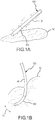
- FIGs. 1A and 1B illustrate a sample embodiment of the present invention.
- PSCC contact sensor 105 includes a catheter shaft 90 and a contact surface 100 that extends from catheter shaft 90.
- contact sensor 105 is flexible such that when it comes into contact with tissue 12, contact sensor 105 is deflected in direction 18 as illustrated in Fig. 1b , and the deflection permits the degree of contact between contact sensor 105 and tissue 12 to be assessed.
- Fig. 2 is a close-up of the sample embodiment depicted in Figs. 1A and 1B .
- Fig. 2 illustrates cross-sectional reference lines A-A and B-B, which will be used to illustrate preferred embodiment of the present invention.
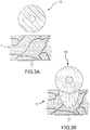
- the PSCC when the PSCC sensor is in a relatively contact free environment (such as air, or in the flowing blood stream while inside a blood vessel or heart chamber), the PSCC is an insulator. When used for a sensing application, however, the PSCC sensor is placed against tissue as illustrated in Fig. 3B . As the contact pressure increases, the PSCC becomes conductive and permits the degree of contact to be assessed by the sensing device. Because of the unique properties of a PSCC, only that portion of the PSCC sensor that is in contact with the tissue becomes conductive. Those portions which are not in direct contact with the tissue, such as the region facing the blood, remain non-conductive, thereby mitigating any current leakage that may cause coagulum and thrombus formation.
- the resistance of a PSCC sensor changes anisotropically, based on the variation of the contact pressure on the PSCC sensor.
- the contact pressure at the sensor-tissue interface is maximum at the point (or line) of normal incidence and gradually decreases along the arc of contact to zero at the edge of the contact. Because of its ability to detect stress forces in any direction, the sensor can be designed to be omnidirectional in use.
- Figs. 4A and 4B illustrate a preferred embodiment of the present invention, revealing two cross sectional drawings taken along the reference lines of A-A and B-B as labeled in Fig. 2 .
- PSCC contact sensor 110 includes a catheter shaft 90 and a contact surface 100 that extends from catheter shaft 90.
- Catheter shaft 90 may be either conductive or non-conductive, and preferably, catheter shaft 90 is non-conductive.
- the PSCC forms the working surface of the sensor that is used for contact assessment.
- PSCC sensor 110 comprises: flexible inner conductive core 111; and an outer PSCC substrate layer 112, which is mechanically and electrically coupled to the flexible inner conductive core 111.
- Flexible inner conductive core 111 may include a flat top (like the top of a right cylinder), or optionally it may include a portion of a sphere on its distal end as illustrated in Fig.
- Flexible inner conductive core 111 may be connected to an electrical conductor 114, which may be connected to an analyzer (not shown). In use, this preferred embodiment is used to assess contact between PSCC sensor 110 and tissue (not shown) to which a reference electrode (not shown) has been attached. PSCC sensor 110 assesses the contact between contact surface 100 and the subject tissue by monitoring the electrical characteristics between two nodes, namely, the reference electrode (not shown) and the flexible inner conductive core 111 (which is preferably measured using electrical conductor 114).
- an analyzer such as an impedance, resistance, capacitance or other electrical measurement device
- an analyzer may be used to measure the electrical characteristics present on electrical conductor 114 relative to the reference electrode (not shown) secured to the tissue being contacted with PSCC sensor 110.
- the reference electrode is grounded to an electrical ground reference signal.
- PSCC sensor 120 extends from a catheter shaft 90, and PSCC sensor 120 comprises: flexible inner conductive coil 121 in the shape of a helix; and a PSCC substrate layer 122 within which the inner conductive coil 121 is located. Flexible inner conductive coil 121 is connected to an electrical conductor 114, which may be connected to an analyzer (not shown). In use, this preferred embodiment is used to assess contact between PSCC sensor 120 and tissue (not shown) to which a reference electrode (not shown) has been attached.
- PSCC sensor 120 assesses the contact between contact surface 100 and the subject tissue by monitoring the electrical characteristics between two nodes, namely, the reference electrode (not shown) and the flexible inner conductive coil 121 (which is preferably measured using electrical conductor 114).
- an analyzer such as an impedance, resistance, capacitance or other electrical measurement device
- the reference electrode is grounded to an electrical ground reference signal.
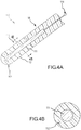
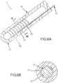
- PSCC sensor 130 extends from a catheter shaft 90, and PSCC sensor 130 comprises: flexible inner conductive coil 131 in the shape of a helix; an outer PSCC substrate layer 132; and an electrically insulative flexible shaft 133 located within the helix of the flexible inner conductive coil 131.
- Flexible shaft 133 may optionally include a portion of a sphere on its distal end as shown in Fig. 6A .
- Flexible inner conductive coil 131 is connected to an electrical conductor 114, which may be connected to an analyzer (not shown).
- this preferred embodiment is used to assess contact between PSCC sensor 130 and tissue (not shown) to which a reference electrode (not shown) has been attached.
- PSCC sensor 130 assesses the contact between contact surface 100 and the subject tissue by monitoring the electrical characteristics between two nodes, namely, the reference electrode (not shown) and the flexible inner conductive coil 131 (which is preferably measured using electrical conductor 114).
- an analyzer such as an impedance, resistance, capacitance or other electrical measurement device
- the reference electrode is grounded to an electrical ground reference signal.
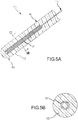
- PSCC sensor 140 extends from a catheter shaft 90, and PSCC sensor 140 comprises: flexible inner conductive sheath 141 formed of a mesh; an outer PSCC substrate layer 142; and an electrically insulative flexible shaft 143 located interiorly of the flexible inner conductive sheath 141.
- Flexible shaft 143 may optionally include a portion of a sphere at its distal end as shown in Fig. 7A .
- Flexible sheath 141 is connected to an electrical conductor 114, which may be connected to an analyzer (not shown).
- this preferred embodiment is used to assess contact between PSCC sensor 140 and tissue (not shown) to which a reference electrode (not shown) has been attached.
- PSCC sensor 140 assesses the contact between contact surface 100 and the subject tissue by monitoring the electrical characteristics between two nodes, namely, the reference electrode (not shown) and the flexible sheath 141 (which is preferably measured using electrical conductor 114).
- an analyzer such as an impedance, resistance, capacitance or other electrical measurement device
- the reference electrode is grounded to an electrical ground reference signal.
- PSCC sensor 150 extends from a catheter shaft 90, and PSCC sensor 150 comprises: an electrically insulative flexible shaft 153; a flexible inner conductive layer 151 (formed, for example, as a coating and/or wrap around flexible shaft 153); and an outer PSCC substrate layer 152. Electrically insulative flexible shaft 153 and flexible inner conductive layer 151 may optionally include a portion of a sphere at their respective distal ends (as illustrated in Fig. 8A ).
- Flexible inner conductive core 151 is connected to an electrical conductor 114, which may be connected to an analyzer (not shown).
- this preferred embodiment is used to assess contact between PSCC sensor 150 and tissue (not shown) to which a reference electrode (not shown) has been attached.
- PSCC sensor 150 assesses the contact between contact surface 100 and the subject tissue by monitoring the electrical characteristics between two nodes, namely, the reference electrode (not shown) and the flexible inner conductive core 151 (which is preferably measured using electrical conductor 114).
- an analyzer such as an impedance, resistance, capacitance or other electrical measurement device
- the reference electrode is grounded to an electrical ground reference signal.
- FIGs. 9A and 9B illustrate an example, revealing two cross sectional drawings taken along the reference lines of A-A and B-B as labeled in Fig. 2 .
- Fig. 9A is a variation of the preferred embodiment illustrated in Fig. 4A .
- PSCC contact sensor 110' includes a catheter shaft 90 and a contact surface 100 that extends from catheter shaft 90.
- Catheter shaft 90 may be either conductive or non-conductive, and preferably, catheter shaft 90 is non-conductive.
- PSCC sensor 110' comprises: flexible inner conductive core 111; and an outer PSCC substrate layer 112, which is mechanically and electrically coupled to the flexible inner conductive core 111.
- Flexible inner conductive core 111 may optionally include a portion of a sphere on its distal end, as illustrated in Fig. 9A .
- Flexible inner conductive core 111 may be connected to an electrical conductor 114, which may be connected to an analyzer (not shown).
- PSCC substrate layer 112 is covered by a conductive outer layer 119, which may be connected to an electrical conductor 116; conductive outer layer 119 may be flexible, rigid, or it may offer an intermediate degree of flexibility.
- this preferred embodiment is used to assess contact between PSCC sensor 110' and tissue by monitoring the electrical characteristics between two nodes, namely, the conductive outer layer 119 (which is preferably measured using electrical conductor 116) and the flexible inner conductive core 111 (which is preferably measured using electrical conductor 114).
- an analyzer such as an impedance, resistance, capacitance or other electrical measurement device
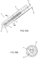
- Figs. 10A and 10B illustrate another example, revealing two cross sectional drawings taken along the reference lines of A-A and B-B as labeled in Fig. 2 .
- Fig. 10A is a variation of the preferred embodiment illustrated in Fig. 5A .
- PSCC sensor 120' extends from a catheter shaft 90, and PSCC sensor 120' comprises: flexible inner conductive coil 121 in the shape of a helix; and a PSCC substrate layer 122 within which the inner conductive coil 121 is located.
- Flexible inner conductive coil 121 is connected to an electrical conductor 114, which may be connected to an analyzer (not shown).
- PSCC substrate layer 112 is covered by a conductive outer layer 119, which may be connected to an electrical conductor 116; conductive outer layer 119 may be flexible, rigid, or it may offer an intermediate degree of flexibility.
- this example is used to assess contact between PSCC sensor 120' and tissue by monitoring the electrical characteristics between two nodes, namely, the conductive outer layer 119 (which is preferably measured using electrical conductor 116) and the flexible inner conductive coil 121 (which is preferably measured using electrical conductor 114).
- an analyzer such as an impedance, resistance, capacitance or other electrical measurement device
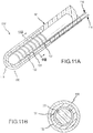
- Figs. 11A and 11B illustrate yet another example, revealing two cross sectional drawings taken along the reference lines of A-A and B-B as labeled in Fig. 2 .
- Fig. 11A is a variation of the preferred embodiment illustrated in Fig. 6A .
- PSCC sensor 130' extends from a catheter shaft 90, and PSCC sensor 130' comprises: flexible inner conductive coil 131 in the shape of a helix; an outer PSCC substrate layer 132; and an electrically insulative flexible shaft 133 located within the helix of the flexible inner conductive coil 131.
- Flexible shaft 133 may optionally include a portion of a sphere on its distal end as shown in Fig.
- PSCC substrate layer 112 is covered by a conductive outer layer 119, which may be connected to an electrical conductor 116; conductive outer layer 119 may be flexible, rigid, or it may offer an intermediate degree of flexibility.
- this preferred embodiment is used to assess contact between PSCC sensor 130' and tissue by monitoring the electrical characteristics between two nodes, namely, the conductive outer layer 119 (which is preferably measured using electrical conductor 116) and the flexible inner conductive coil 131 (which is preferably measured using electrical conductor 114).
- an analyzer such as an impedance, resistance, capacitance or other electrical measurement device
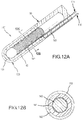
- Figs. 12A and 12B illustrate yet another example, revealing two cross sectional drawings taken along the reference lines of A-A and B-B as labeled in Fig. 2 .
- Fig. 12A is a variation of the preferred embodiment illustrated in Fig. 7A .
- PSCC sensor 140' extends from a catheter shaft 90, and PSCC sensor 140' comprises: flexible inner conductive sheath 141 formed of a mesh; an outer PSCC substrate layer 142; and an electrically insulative flexible shaft 143 located interiorly of the flexible inner conductive sheath 141.
- Flexible shaft 143 may optionally include a portion of a sphere at its distal end as shown in Fig. 7A .
- Flexible sheath 141 is connected to an electrical conductor 114, which may be connected to an analyzer (not shown).
- PSCC substrate layer 112 is covered by a conductive outer layer 119, which may be connected to an electrical conductor 116; conductive outer layer 119 may be flexible, rigid, or it may offer an intermediate degree of flexibility.
- this preferred embodiment is used to assess contact between PSCC sensor 140' and tissue by monitoring the electrical characteristics between two nodes, namely, the conductive outer layer 119 (which is preferably measured using electrical conductor 116) and the flexible sheath 141 (which is preferably measured using electrical conductor 114).
- an analyzer such as an impedance, resistance, capacitance or other electrical measurement device
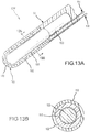
- FIG. 13A is a variation of the preferred embodiment illustrated in Fig. 8A .
- PSCC sensor 150' extends from a catheter shaft 90, and PSCC sensor 150' comprises: an electrically insulative flexible shaft 153; a flexible inner conductive layer 151 (formed, for example, as a coating and/or wrap around flexible shaft 153); and an outer PSCC substrate layer 152.
- Electrically insulative flexible shaft 153 and flexible inner conductive layer 151 may optionally include a portion of a sphere at their respective distal ends (as illustrated in Fig. 13A ).
- Flexible inner conductive core 151 is connected to an electrical conductor 114, which may be connected to an analyzer (not shown).
- PSCC substrate layer 112 is covered by a conductive outer layer 119, which may be connected to an electrical conductor 116; conductive outer layer 119 may be flexible, rigid, or it may offer an intermediate degree of flexibility.
- this preferred embodiment is used to assess contact between PSCC sensor 150' and tissue by monitoring the electrical characteristics between two nodes, namely, the conductive outer layer 119 (which is preferably measured using electrical conductor 116) and the flexible inner conductive core 151 (which is preferably measured using electrical conductor 114).
- an analyzer such as an impedance, resistance, capacitance or other electrical measurement device
- Electrical conductors 114 and 116 may be implemented using a single conductive wire or multiple strands of wire.
- the wires may be made of flexible conductive materials which allow the surface contacting area to be bent and formed into various shapes to provide better contact to the tissue.
- Acceptable materials include, but are not limited to, stainless steel, nickel titanium (nitinol), tantalum, copper, platinum, iridium, gold, or silver, and combinations thereof.
- the material used to manufacture the conductive element is a bio-compatible electrically conductive material, such as platinum, gold, silver, nickel titanium, and combinations thereof.
- Other electrically conductive materials coated with bio-compatible materials may also be employed, including for example, gold-plated copper.
- electrically conductive polymers may also be used provided they are bio-compatible or coated with a bio-compatible material.
- the present invention permits the construction of a flexible, pressure sensitive contact assessment device that can be used in a wide variety of different tissue environments, including for example, tissues having varying degrees of elasticity and contour.
- the present invention permits the construction of a flexible sensor to measure pressure that is applied to the sensor, for example, pressure that may be applied to the sensor by the myocardium.
- Such sensors may be used to measure the pressure that is applied directly to the sensor, or depending on the configuration of the sensor, it may measure the pressure that is applied to a component that is in contact with the sensor (as may be the case when an additional element is disposed between a PSCC-based sensor and tissue that is exerting pressure on the additional element).
- the PSCC-based sensor is preferably used to measure pressure that is applied axially to catheter.
- the PSCC based sensor could be oriented in order to measure pressure that is applied transversely to the catheter.
- the present invention also contemplates that the contact sensor may be formed into various shapes to better fit the contour of the target tissue.
- the contact sensor can be made long enough to strap around and form a noose around the pulmonary veins in epicardial applications.
- the conductive element that is coupled to the PSCC for example, reference numbers 111, 121, 131, 141, and 151 may be formed into a desired shape and then the PSCC layer will be formed over the conductive element in the preferred shape.
- the contact sensor may be shaped like a spatula for certain applications, including for example, minimally invasive sub-xyphoid epicardial applications, where the spatula shape will permit easy placement and navigation in the pericardial sac.
- PSCC can be made to be a flexible material, it can be used for form electrodes having a great variety of shapes, including a spatula.
- the conductive element that is coupled to the PSCC may be formed using shape-memory retaining material, such as nitinol, which would permit the electrode to be fitted to specific preset geometries, such as the ostium of a pulmonary vein, such that the electrode is shaped to provide a desired contact pressure pattern on the tissue due to the deformation of the wire when pressed against the tissue.
- shape-memory retaining material such as nitinol
- insulative shaft for example, 133, 143, and 153
- the insulative shaft could be in a geometric shape other than a cylinder, including, for example, a noose, a spatula, or the shape of the ostium of a pulmonary vein.
- insulative shaft is intended to encompass shapes in addition to a cylindrical shaft.
- the conductive element that is coupled to the PSCC may be formed in the shape of a helix, such as is the case with elements 121, and 131
- the coil may be chosen to be of a specific stiffness (i. e., having a characteristic spring constant) that would allow the coil to exert a desired amount of pressure on the PSCC when the electrode bends or deflects upon contact with the tissue.
- a specific stiffness i. e., having a characteristic spring constant
- the degree of desired contact pressure would depend in part upon the elastic property of the tissue being contacted with the electrode.
- the atrial wall may require less contact pressure than the ventricular wall.
- electrodes of varying stiffness can be designed for application in different tissues and different regions of the heart.
- the conductive element may be mounted on an insulative shaft.
- the conductive element can be shaped in any number of ways, including for example, a coil, mesh, coating or wrap.
- the insulative shaft provides additional mechanical support in applications that require greater amounts of axial pressure and torque.
- the insulative shaft may be made of any electrically insulative material, including, for example, polyurethane.
- the insulative shaft is made of a biocompatible, electrically insulative material.
- any of the contact sensors described above may be used with a memory device to record information regarding one or more forces that are applied to the sensor.
- a first known pressure may be applied to the contact sensor and a first measurement of an electrical characteristic may be made such that the first known pressure may be associated with the first measurement.
- a second known pressure may be applied to the contact sensor and a second measurement of an electrical characteristic may be made such that the second known pressure may be associated with the second measurement.
- Additional known pressures may be applied and additional corresponding measurements may be made and associated. Then, if an unknown pressure is applied, the processor may use the known pressures and their respective associated measurements to help quantify the unknown pressure.
- the embodiments above can also be used to assess forces relative to contact between tissue and the contact sensor.
- Pressure is simply a measurement of the forces per unit area, and thus, to assess force, the surface area of a contact surface must be known or be capable of being determined or calculated.
- the force information may be derived from the information available on forces and the contact surface area.
- each of the embodiments discussed above may optionally be used in connection with one or more electrically-conductive, outer protective coverings.
- the outer covering is electrically conductive, such as a flexible wire mesh, a conductive fabric, a conductive polymer layer (which can be porous or nonporous), or a metal coating.
- the outer covering may be used to not only increase the mechanical integrity, but to enhance the contact sensor's ability to assess the tissue contact (for example, in the when measuring electrical characteristics using a reference electrode connected to the target tissue).
- the outer covering may be made using a biocompatible material in order to help make the overall assembly biocompatible.
- an electrically non-conductive outer protective covering may be desirable to optionally use.
- the outer covering may be made using a biocompatible material in order to help make the overall assembly biocompatible.
- Such an electrically-non-conductive covering may also serve as a pressure transfer element to more evenly distribute pressure to the pressure sensitive conductive composite member.
- PSCC materials may be designed to respond to a variety of stresses, the principles and embodiments herein may be adapted to respond to specific stress forces, for example, axial forces, orthogonal forces, twisting, compressing, stretching, etc., without deviating from the scope of the present invention.
Claims (3)
- Katheteraufbau zur Beurteilung eines Kontakts zwischen dem Katheteraufbau und Gewebe, wobei der Aufbau aufweist:einen Katheterschaft (90);einen flexiblen inneren leitfähigen Kern (111, 121, 131, 141, 151);ein druckempfindliches leitfähiges Verbundelement (112, 122, 132, 142, 152), das mechanisch und elektrisch mit dem flexiblen inneren leitfähigen Kern gekoppelt ist, wobei das druckempfindliche leitfähige Verbundelement derart konfiguriert ist, dass ein Druck, der auf den Katheteraufbau einwirkt, das druckempfindliche leitfähige Verbundelement veranlasst seinen elektrischen Widerstand derart zu ändern, dass sein elektrischer Widerstand hoch ist, wenn kein Druck wirkt, und es unter Druck leitfähig wird;mindestens einen Messanschluss, der eine Messung von Änderungen des Widerstands des druckempfindlichen leitfähigen Verbundelements erlaubt,eine Messvorrichtung, die mit dem mindestens einen Messanschluss gekoppelt ist, zum Messen von Änderungen des Widerstands des druckempfindlichen leitfähigen Verbundelements, undeine Referenzelektrode, die angepasst ist zur Befestigung an dem Gewebe, das mit dem Katheteraufbau in Kontakt kommen kann, wobei die Referenzelektrode auch mit der Messvorrichtung derart gekoppelt ist, dass die Messvorrichtung angepasst ist zum Messen von Änderungen des Widerstands des druckempfindlichen leitfähigen Verbundelements basierend auf Änderungen der elektrischen Charakteristiken zwischen der Referenzelektrode und dem mindestens einen Messanschluss.
- Katheteraufbau nach Anspruch 1, bei dem die Referenzelektrode mit einer elektrischen Masse verbunden ist.
- Katheteraufbau nach Anspruch 1 oder 2, bei dem das druckempfindliche leitfähige Verbundelement eine Quanten-Tunneling-Komponente ist.
Applications Claiming Priority (2)
| Application Number | Priority Date | Filing Date | Title |
|---|---|---|---|
| US11/647,314 US9579483B2 (en) | 2006-12-29 | 2006-12-29 | Pressure-sensitive conductive composite contact sensor and method for contact sensing |
| PCT/US2007/089099 WO2008083311A2 (en) | 2006-12-29 | 2007-12-28 | Pressure-sensitive conductive composite contact sensor and method for contact sensing |
Publications (3)
| Publication Number | Publication Date |
|---|---|
| EP2097034A2 EP2097034A2 (de) | 2009-09-09 |
| EP2097034A4 EP2097034A4 (de) | 2011-07-27 |
| EP2097034B1 true EP2097034B1 (de) | 2018-06-27 |
Family
ID=39585032
Family Applications (1)
| Application Number | Title | Priority Date | Filing Date |
|---|---|---|---|
| EP07871747.7A Not-in-force EP2097034B1 (de) | 2006-12-29 | 2007-12-28 | Druckempfindlicher und leitfähiger verbundkontaktsensor |
Country Status (4)
| Country | Link |
|---|---|
| US (2) | US9579483B2 (de) |
| EP (1) | EP2097034B1 (de) |
| JP (1) | JP5254253B2 (de) |
| WO (1) | WO2008083311A2 (de) |
Families Citing this family (8)
| Publication number | Priority date | Publication date | Assignee | Title |
|---|---|---|---|---|
| EP2651284A4 (de) * | 2010-12-13 | 2017-02-15 | Case Western Reserve University | Vorrichtung mit externen drucksensoren für verbesserte patientenpflege und verwendungsverfahren dafür |
| US10905494B2 (en) | 2011-12-29 | 2021-02-02 | St. Jude Medical, Atrial Fibrillation Division, Inc | Flexible conductive polymer based conformable device and method to create linear endocardial lesions |
| WO2014164098A1 (en) * | 2013-03-13 | 2014-10-09 | Brigham And Women's Hospital, Inc. | Safely ingestible batteries |
| WO2017136548A1 (en) | 2016-02-04 | 2017-08-10 | Cardiac Pacemakers, Inc. | Delivery system with force sensor for leadless cardiac device |
| JP6880583B2 (ja) * | 2016-07-11 | 2021-06-02 | ニプロ株式会社 | 圧力測定装置 |
| EP3292812A1 (de) * | 2016-09-12 | 2018-03-14 | Heraeus Deutschland GmbH & Co. KG | Piezoresistives material |
| EP3400865B1 (de) * | 2017-05-08 | 2021-11-03 | Heraeus Deutschland GmbH & Co. KG | Sensor basierend auf leitfähigem polymerverbundmaterial |
| CN107823756B (zh) * | 2017-10-12 | 2021-03-12 | 英华达(上海)科技有限公司 | 输液装置 |
Citations (3)
| Publication number | Priority date | Publication date | Assignee | Title |
|---|---|---|---|---|
| JPH06154154A (ja) * | 1992-11-17 | 1994-06-03 | Olympus Optical Co Ltd | 管路内挿入装置 |
| JPH09135905A (ja) * | 1995-11-17 | 1997-05-27 | Tokai Rika Co Ltd | 体内挿入式医療器具用のセンサ及びその製造方法 |
| WO1997018754A1 (en) * | 1995-11-20 | 1997-05-29 | Postur Phonic Technologies, Inc. | Bio feedback sensor system |
Family Cites Families (67)
| Publication number | Priority date | Publication date | Assignee | Title |
|---|---|---|---|---|
| JPS5998408A (ja) * | 1982-11-29 | 1984-06-06 | 横浜ゴム株式会社 | 感圧型導電性複合シ−ト |
| US4911174A (en) | 1989-02-13 | 1990-03-27 | Cardiac Pacemakers, Inc. | Method for matching the sense length of an impedance measuring catheter to a ventricular chamber |
| US5006119A (en) | 1989-05-25 | 1991-04-09 | Engineering & Research Associates, Inc. | Hollow core coaxial catheter |
| JP3087294B2 (ja) * | 1989-09-29 | 2000-09-11 | ジェイエスアール株式会社 | 異方導電性シートの製造方法 |
| US5028394A (en) | 1990-04-13 | 1991-07-02 | Bend Research, Inc. | Chemical sensors |
| JP3139561B2 (ja) * | 1991-12-26 | 2001-03-05 | 鐘淵化学工業株式会社 | 拡張カテーテル |
| US5341807A (en) | 1992-06-30 | 1994-08-30 | American Cardiac Ablation Co., Inc. | Ablation catheter positioning system |
| US5313840A (en) * | 1992-10-30 | 1994-05-24 | At&T Bell Laboratories | Tactile shear sensor using anisotropically conductive material |
| US5545161A (en) * | 1992-12-01 | 1996-08-13 | Cardiac Pathways Corporation | Catheter for RF ablation having cooled electrode with electrically insulated sleeve |
| US5472441A (en) * | 1993-11-08 | 1995-12-05 | Zomed International | Device for treating cancer and non-malignant tumors and methods |
| JPH07204278A (ja) * | 1994-01-17 | 1995-08-08 | Mitsubishi Cable Ind Ltd | 触覚センサおよびそれを取着してなる体内挿入用医療器具 |
| US5382247A (en) * | 1994-01-21 | 1995-01-17 | Valleylab Inc. | Technique for electrosurgical tips and method of manufacture and use |
| US5447539A (en) | 1994-02-10 | 1995-09-05 | Dke Incorporated | Method of dyeing polypropylene fiber with more than one color |
| US6246898B1 (en) | 1995-03-28 | 2001-06-12 | Sonometrics Corporation | Method for carrying out a medical procedure using a three-dimensional tracking and imaging system |
| US6322558B1 (en) | 1995-06-09 | 2001-11-27 | Engineering & Research Associates, Inc. | Apparatus and method for predicting ablation depth |
| US5868737A (en) | 1995-06-09 | 1999-02-09 | Engineering Research & Associates, Inc. | Apparatus and method for determining ablation |
| US5697925A (en) | 1995-06-09 | 1997-12-16 | Engineering & Research Associates, Inc. | Apparatus and method for thermal ablation |
| US6113592A (en) | 1995-06-09 | 2000-09-05 | Engineering & Research Associates, Inc. | Apparatus and method for controlling ablation depth |
| US5685878A (en) * | 1995-11-13 | 1997-11-11 | C.R. Bard, Inc. | Snap fit distal assembly for an ablation catheter |
| JPH09135906A (ja) * | 1995-11-17 | 1997-05-27 | Tokai Rika Co Ltd | 体内挿入式医療器具用のセンサ |
| JPH09149941A (ja) * | 1995-12-01 | 1997-06-10 | Tokai Rika Co Ltd | 体内挿入用医療器具のセンサ |
| US6066139A (en) | 1996-05-14 | 2000-05-23 | Sherwood Services Ag | Apparatus and method for sterilization and embolization |
| US6544193B2 (en) * | 1996-09-04 | 2003-04-08 | Marcio Marc Abreu | Noninvasive measurement of chemical substances |
| SI0901341T1 (en) | 1997-01-03 | 2005-04-30 | Biosense Webster, Inc. | Bend-responsive catheter |
| CN1248341A (zh) * | 1997-01-25 | 2000-03-22 | 佩拉泰克有限公司 | 聚合物组合物 |
| US5913854A (en) * | 1997-02-04 | 1999-06-22 | Medtronic, Inc. | Fluid cooled ablation catheter and method for making |
| JP4105238B2 (ja) | 1997-04-01 | 2008-06-25 | ムンターマン,アクセル | カテーテルと組織の接触を検知するとともにカテーテル切除の際に組織との相互作用を検知するためのシステム |
| AU6880598A (en) | 1997-04-04 | 1998-10-30 | Minnesota Mining And Manufacturing Company | Method and apparatus for controlling contact of biomedical electrodes with patient skin |
| GB9708268D0 (en) | 1997-04-24 | 1997-06-18 | Gyrus Medical Ltd | An electrosurgical instrument |
| US5836990A (en) | 1997-09-19 | 1998-11-17 | Medtronic, Inc. | Method and apparatus for determining electrode/tissue contact |
| US5947905A (en) | 1997-10-15 | 1999-09-07 | Advanced Coronary Intervention, Inc. | Ultrasound transducer array probe for intraluminal imaging catheter |
| US6495069B1 (en) * | 1998-01-30 | 2002-12-17 | Peratech Limited Of A Company Of Great Britain And Northern Ireland | Polymer composition |
| US6312425B1 (en) * | 1998-05-05 | 2001-11-06 | Cardiac Pacemakers, Inc. | RF ablation catheter tip electrode with multiple thermal sensors |
| US6845264B1 (en) | 1998-10-08 | 2005-01-18 | Victor Skladnev | Apparatus for recognizing tissue types |
| US6210406B1 (en) | 1998-12-03 | 2001-04-03 | Cordis Webster, Inc. | Split tip electrode catheter and signal processing RF ablation system |
| US6423057B1 (en) | 1999-01-25 | 2002-07-23 | The Arizona Board Of Regents On Behalf Of The University Of Arizona | Method and apparatus for monitoring and controlling tissue temperature and lesion formation in radio-frequency ablation procedures |
| US6113593A (en) | 1999-02-01 | 2000-09-05 | Tu; Lily Chen | Ablation apparatus having temperature and force sensing capabilities |
| US6696844B2 (en) | 1999-06-04 | 2004-02-24 | Engineering & Research Associates, Inc. | Apparatus and method for real time determination of materials' electrical properties |
| US6391024B1 (en) | 1999-06-17 | 2002-05-21 | Cardiac Pacemakers, Inc. | RF ablation apparatus and method having electrode/tissue contact assessment scheme and electrocardiogram filtering |
| EP1188170B1 (de) * | 1999-06-22 | 2004-05-26 | Peratech Ltd. | Strukturen mit veränderlichem Leitwert |
| SE514744C2 (sv) | 1999-07-06 | 2001-04-09 | Samba Sensors Ab | Förfarande och anordning vid optiska mätsystem |
| US6264653B1 (en) | 1999-09-24 | 2001-07-24 | C. R. Band, Inc. | System and method for gauging the amount of electrode-tissue contact using pulsed radio frequency energy |
| US6394956B1 (en) * | 2000-02-29 | 2002-05-28 | Scimed Life Systems, Inc. | RF ablation and ultrasound catheter for crossing chronic total occlusions |
| CA2408176A1 (en) * | 2000-05-12 | 2001-11-22 | Cardima, Inc. | Multi-channel rf energy delivery with coagulum reduction |
| DE60215766T2 (de) * | 2001-01-11 | 2007-09-06 | C.R. Bard, Inc. | Ablationskatheter |
| US7422586B2 (en) * | 2001-02-28 | 2008-09-09 | Angiodynamics, Inc. | Tissue surface treatment apparatus and method |
| US6666862B2 (en) | 2001-03-01 | 2003-12-23 | Cardiac Pacemakers, Inc. | Radio frequency ablation system and method linking energy delivery with fluid flow |
| US20040133092A1 (en) * | 2001-03-27 | 2004-07-08 | Kain Aron Z. | Wireless system for measuring distension in flexible tubes |
| US6620159B2 (en) * | 2001-06-06 | 2003-09-16 | Scimed Life Systems, Inc. | Conductive expandable electrode body and method of manufacturing the same |
| US6730082B2 (en) * | 2001-07-09 | 2004-05-04 | Scimed Life Systems, Inc. | Two-piece distal catheter assembly |
| US7070597B2 (en) | 2001-10-18 | 2006-07-04 | Surgrx, Inc. | Electrosurgical working end for controlled energy delivery |
| US7125409B2 (en) * | 2001-10-22 | 2006-10-24 | Surgrx, Inc. | Electrosurgical working end for controlled energy delivery |
| US6999821B2 (en) * | 2002-01-18 | 2006-02-14 | Pacesetter, Inc. | Body implantable lead including one or more conductive polymer electrodes and methods for fabricating same |
| US6882885B2 (en) | 2002-03-19 | 2005-04-19 | Solarant Medical, Inc. | Heating method for tissue contraction |
| US6814731B2 (en) * | 2002-05-20 | 2004-11-09 | Scimed Life Systems, Inc. | Methods for RF ablation using jet injection of conductive fluid |
| EP1527382A2 (de) * | 2002-08-01 | 2005-05-04 | Koninklijke Philips Electronics N.V. | Berührungsempfindliches anzeigegerät |
| US20040133166A1 (en) * | 2002-11-22 | 2004-07-08 | Minimed Inc. | Methods, apparatuses, and uses for infusion pump fluid pressure and force detection |
| US20060249705A1 (en) * | 2003-04-08 | 2006-11-09 | Xingwu Wang | Novel composition |
| JP2006528366A (ja) * | 2003-05-14 | 2006-12-14 | テクスカン・インコーポレーテッド | 高温感圧装置及びその方法 |
| WO2005039390A2 (en) * | 2003-10-20 | 2005-05-06 | Arthrocare Corporation | Electrosurgical method and apparatus for removing tissue within a bone body |
| US7974681B2 (en) * | 2004-03-05 | 2011-07-05 | Hansen Medical, Inc. | Robotic catheter system |
| US7311704B2 (en) * | 2004-05-27 | 2007-12-25 | St. Jude Medical, Atrial Fibrillation Division, Inc. | Spring-tip, flexible electrode catheter for tissue ablation |
| US7276064B2 (en) * | 2004-05-27 | 2007-10-02 | St. Jude Medical, Atrial Fibrillation Division, Inc. | Side-port sheath for catheter placement and translation |
| JP4728338B2 (ja) * | 2004-10-11 | 2011-07-20 | コンヴァテック テクノロジーズ インコーポレイテッド | 電気的に作動する圧縮バンド |
| US7093499B2 (en) * | 2004-12-21 | 2006-08-22 | Delphi Technologies, Inc. | Force sensor, strain sensor and methods for measuring same |
| US20060270916A1 (en) * | 2005-05-20 | 2006-11-30 | Medtronic, Inc. | Portable therapy delivery device with a removable connector board |
| US20070062546A1 (en) * | 2005-06-02 | 2007-03-22 | Viswanathan Raju R | Electrophysiology catheter and system for gentle and firm wall contact |
-
2006
- 2006-12-29 US US11/647,314 patent/US9579483B2/en active Active
-
2007
- 2007-12-28 EP EP07871747.7A patent/EP2097034B1/de not_active Not-in-force
- 2007-12-28 WO PCT/US2007/089099 patent/WO2008083311A2/en active Application Filing
- 2007-12-28 JP JP2009544302A patent/JP5254253B2/ja not_active Expired - Fee Related
-
2017
- 2017-01-12 US US15/404,844 patent/US10687891B2/en active Active
Patent Citations (3)
| Publication number | Priority date | Publication date | Assignee | Title |
|---|---|---|---|---|
| JPH06154154A (ja) * | 1992-11-17 | 1994-06-03 | Olympus Optical Co Ltd | 管路内挿入装置 |
| JPH09135905A (ja) * | 1995-11-17 | 1997-05-27 | Tokai Rika Co Ltd | 体内挿入式医療器具用のセンサ及びその製造方法 |
| WO1997018754A1 (en) * | 1995-11-20 | 1997-05-29 | Postur Phonic Technologies, Inc. | Bio feedback sensor system |
Also Published As
| Publication number | Publication date |
|---|---|
| WO2008083311A3 (en) | 2008-10-09 |
| US20080161786A1 (en) | 2008-07-03 |
| US10687891B2 (en) | 2020-06-23 |
| US9579483B2 (en) | 2017-02-28 |
| JP5254253B2 (ja) | 2013-08-07 |
| WO2008083311A2 (en) | 2008-07-10 |
| EP2097034A2 (de) | 2009-09-09 |
| US20170202615A1 (en) | 2017-07-20 |
| EP2097034A4 (de) | 2011-07-27 |
| JP2010514523A (ja) | 2010-05-06 |
Similar Documents
| Publication | Publication Date | Title |
|---|---|---|
| US20190053848A1 (en) | Design of Ablation Electrode with Tactile Sensor | |
| US10687891B2 (en) | Pressure-sensitive conductive composite contact sensor and method for contact sensing | |
| US7955326B2 (en) | Pressure-sensitive conductive composite electrode and method for ablation | |
| US7883508B2 (en) | Contact-sensitive pressure-sensitive conductive composite electrode and method for ablation | |
| US8211102B2 (en) | Contact sensing flexible conductive polymer electrode | |
| US8118809B2 (en) | Flexible conductive polymer electrode and method for ablation | |
| AU2006305967B2 (en) | Systems and methods for electrode contact assessment | |
| US8500731B2 (en) | Adjustable length flexible polymer electrode catheter and method for ablation | |
| EP3571983B1 (de) | Katheter mit kapazitivem kraftsensor | |
| JP2010514523A5 (de) | ||
| US10905494B2 (en) | Flexible conductive polymer based conformable device and method to create linear endocardial lesions | |
| JP6941030B2 (ja) | 電極カテーテル | |
| CN113855216A (zh) | 一种医疗导管 |
Legal Events
| Date | Code | Title | Description |
|---|---|---|---|
| PUAI | Public reference made under article 153(3) epc to a published international application that has entered the european phase |
Free format text: ORIGINAL CODE: 0009012 |
|
| 17P | Request for examination filed |
Effective date: 20090629 |
|
| AK | Designated contracting states |
Kind code of ref document: A2 Designated state(s): AT BE BG CH CY CZ DE DK EE ES FI FR GB GR HU IE IS IT LI LT LU LV MC MT NL PL PT RO SE SI SK TR |
|
| DAX | Request for extension of the european patent (deleted) | ||
| A4 | Supplementary search report drawn up and despatched |
Effective date: 20110624 |
|
| 17Q | First examination report despatched |
Effective date: 20131021 |
|
| REG | Reference to a national code |
Ref country code: DE Ref legal event code: R079 Ref document number: 602007055241 Country of ref document: DE Free format text: PREVIOUS MAIN CLASS: A61B0019000000 Ipc: A61B0005000000 |
|
| RIC1 | Information provided on ipc code assigned before grant |
Ipc: A61B 5/00 20060101AFI20171208BHEP |
|
| GRAP | Despatch of communication of intention to grant a patent |
Free format text: ORIGINAL CODE: EPIDOSNIGR1 |
|
| INTG | Intention to grant announced |
Effective date: 20180122 |
|
| GRAS | Grant fee paid |
Free format text: ORIGINAL CODE: EPIDOSNIGR3 |
|
| GRAA | (expected) grant |
Free format text: ORIGINAL CODE: 0009210 |
|
| AK | Designated contracting states |
Kind code of ref document: B1 Designated state(s): AT BE BG CH CY CZ DE DK EE ES FI FR GB GR HU IE IS IT LI LT LU LV MC MT NL PL PT RO SE SI SK TR |
|
| REG | Reference to a national code |
Ref country code: GB Ref legal event code: FG4D |
|
| REG | Reference to a national code |
Ref country code: AT Ref legal event code: REF Ref document number: 1011584 Country of ref document: AT Kind code of ref document: T Effective date: 20180715 |
|
| REG | Reference to a national code |
Ref country code: DE Ref legal event code: R096 Ref document number: 602007055241 Country of ref document: DE |
|
| REG | Reference to a national code |
Ref country code: IE Ref legal event code: FG4D |
|
| PG25 | Lapsed in a contracting state [announced via postgrant information from national office to epo] |
Ref country code: SE Free format text: LAPSE BECAUSE OF FAILURE TO SUBMIT A TRANSLATION OF THE DESCRIPTION OR TO PAY THE FEE WITHIN THE PRESCRIBED TIME-LIMIT Effective date: 20180627 Ref country code: FI Free format text: LAPSE BECAUSE OF FAILURE TO SUBMIT A TRANSLATION OF THE DESCRIPTION OR TO PAY THE FEE WITHIN THE PRESCRIBED TIME-LIMIT Effective date: 20180627 Ref country code: BG Free format text: LAPSE BECAUSE OF FAILURE TO SUBMIT A TRANSLATION OF THE DESCRIPTION OR TO PAY THE FEE WITHIN THE PRESCRIBED TIME-LIMIT Effective date: 20180927 Ref country code: LT Free format text: LAPSE BECAUSE OF FAILURE TO SUBMIT A TRANSLATION OF THE DESCRIPTION OR TO PAY THE FEE WITHIN THE PRESCRIBED TIME-LIMIT Effective date: 20180627 |
|
| REG | Reference to a national code |
Ref country code: NL Ref legal event code: MP Effective date: 20180627 |
|
| REG | Reference to a national code |
Ref country code: LT Ref legal event code: MG4D |
|
| PG25 | Lapsed in a contracting state [announced via postgrant information from national office to epo] |
Ref country code: GR Free format text: LAPSE BECAUSE OF FAILURE TO SUBMIT A TRANSLATION OF THE DESCRIPTION OR TO PAY THE FEE WITHIN THE PRESCRIBED TIME-LIMIT Effective date: 20180928 Ref country code: LV Free format text: LAPSE BECAUSE OF FAILURE TO SUBMIT A TRANSLATION OF THE DESCRIPTION OR TO PAY THE FEE WITHIN THE PRESCRIBED TIME-LIMIT Effective date: 20180627 |
|
| REG | Reference to a national code |
Ref country code: AT Ref legal event code: MK05 Ref document number: 1011584 Country of ref document: AT Kind code of ref document: T Effective date: 20180627 |
|
| PG25 | Lapsed in a contracting state [announced via postgrant information from national office to epo] |
Ref country code: NL Free format text: LAPSE BECAUSE OF FAILURE TO SUBMIT A TRANSLATION OF THE DESCRIPTION OR TO PAY THE FEE WITHIN THE PRESCRIBED TIME-LIMIT Effective date: 20180627 |
|
| PG25 | Lapsed in a contracting state [announced via postgrant information from national office to epo] |
Ref country code: CZ Free format text: LAPSE BECAUSE OF FAILURE TO SUBMIT A TRANSLATION OF THE DESCRIPTION OR TO PAY THE FEE WITHIN THE PRESCRIBED TIME-LIMIT Effective date: 20180627 Ref country code: RO Free format text: LAPSE BECAUSE OF FAILURE TO SUBMIT A TRANSLATION OF THE DESCRIPTION OR TO PAY THE FEE WITHIN THE PRESCRIBED TIME-LIMIT Effective date: 20180627 Ref country code: AT Free format text: LAPSE BECAUSE OF FAILURE TO SUBMIT A TRANSLATION OF THE DESCRIPTION OR TO PAY THE FEE WITHIN THE PRESCRIBED TIME-LIMIT Effective date: 20180627 Ref country code: EE Free format text: LAPSE BECAUSE OF FAILURE TO SUBMIT A TRANSLATION OF THE DESCRIPTION OR TO PAY THE FEE WITHIN THE PRESCRIBED TIME-LIMIT Effective date: 20180627 Ref country code: IS Free format text: LAPSE BECAUSE OF FAILURE TO SUBMIT A TRANSLATION OF THE DESCRIPTION OR TO PAY THE FEE WITHIN THE PRESCRIBED TIME-LIMIT Effective date: 20181027 Ref country code: PL Free format text: LAPSE BECAUSE OF FAILURE TO SUBMIT A TRANSLATION OF THE DESCRIPTION OR TO PAY THE FEE WITHIN THE PRESCRIBED TIME-LIMIT Effective date: 20180627 Ref country code: SK Free format text: LAPSE BECAUSE OF FAILURE TO SUBMIT A TRANSLATION OF THE DESCRIPTION OR TO PAY THE FEE WITHIN THE PRESCRIBED TIME-LIMIT Effective date: 20180627 |
|
| PG25 | Lapsed in a contracting state [announced via postgrant information from national office to epo] |
Ref country code: ES Free format text: LAPSE BECAUSE OF FAILURE TO SUBMIT A TRANSLATION OF THE DESCRIPTION OR TO PAY THE FEE WITHIN THE PRESCRIBED TIME-LIMIT Effective date: 20180627 |
|
| REG | Reference to a national code |
Ref country code: DE Ref legal event code: R097 Ref document number: 602007055241 Country of ref document: DE |
|
| PLBE | No opposition filed within time limit |
Free format text: ORIGINAL CODE: 0009261 |
|
| STAA | Information on the status of an ep patent application or granted ep patent |
Free format text: STATUS: NO OPPOSITION FILED WITHIN TIME LIMIT |
|
| PG25 | Lapsed in a contracting state [announced via postgrant information from national office to epo] |
Ref country code: DK Free format text: LAPSE BECAUSE OF FAILURE TO SUBMIT A TRANSLATION OF THE DESCRIPTION OR TO PAY THE FEE WITHIN THE PRESCRIBED TIME-LIMIT Effective date: 20180627 |
|
| 26N | No opposition filed |
Effective date: 20190328 |
|
| REG | Reference to a national code |
Ref country code: CH Ref legal event code: PL |
|
| PG25 | Lapsed in a contracting state [announced via postgrant information from national office to epo] |
Ref country code: SI Free format text: LAPSE BECAUSE OF FAILURE TO SUBMIT A TRANSLATION OF THE DESCRIPTION OR TO PAY THE FEE WITHIN THE PRESCRIBED TIME-LIMIT Effective date: 20180627 Ref country code: MC Free format text: LAPSE BECAUSE OF FAILURE TO SUBMIT A TRANSLATION OF THE DESCRIPTION OR TO PAY THE FEE WITHIN THE PRESCRIBED TIME-LIMIT Effective date: 20180627 Ref country code: LU Free format text: LAPSE BECAUSE OF NON-PAYMENT OF DUE FEES Effective date: 20181228 |
|
| REG | Reference to a national code |
Ref country code: IE Ref legal event code: MM4A |
|
| REG | Reference to a national code |
Ref country code: BE Ref legal event code: MM Effective date: 20181231 |
|
| PG25 | Lapsed in a contracting state [announced via postgrant information from national office to epo] |
Ref country code: IE Free format text: LAPSE BECAUSE OF NON-PAYMENT OF DUE FEES Effective date: 20181228 |
|
| PG25 | Lapsed in a contracting state [announced via postgrant information from national office to epo] |
Ref country code: BE Free format text: LAPSE BECAUSE OF NON-PAYMENT OF DUE FEES Effective date: 20181231 |
|
| PG25 | Lapsed in a contracting state [announced via postgrant information from national office to epo] |
Ref country code: LI Free format text: LAPSE BECAUSE OF NON-PAYMENT OF DUE FEES Effective date: 20181231 Ref country code: CH Free format text: LAPSE BECAUSE OF NON-PAYMENT OF DUE FEES Effective date: 20181231 |
|
| PG25 | Lapsed in a contracting state [announced via postgrant information from national office to epo] |
Ref country code: MT Free format text: LAPSE BECAUSE OF NON-PAYMENT OF DUE FEES Effective date: 20181228 |
|
| PG25 | Lapsed in a contracting state [announced via postgrant information from national office to epo] |
Ref country code: TR Free format text: LAPSE BECAUSE OF FAILURE TO SUBMIT A TRANSLATION OF THE DESCRIPTION OR TO PAY THE FEE WITHIN THE PRESCRIBED TIME-LIMIT Effective date: 20180627 |
|
| PG25 | Lapsed in a contracting state [announced via postgrant information from national office to epo] |
Ref country code: PT Free format text: LAPSE BECAUSE OF FAILURE TO SUBMIT A TRANSLATION OF THE DESCRIPTION OR TO PAY THE FEE WITHIN THE PRESCRIBED TIME-LIMIT Effective date: 20180627 |
|
| PG25 | Lapsed in a contracting state [announced via postgrant information from national office to epo] |
Ref country code: CY Free format text: LAPSE BECAUSE OF FAILURE TO SUBMIT A TRANSLATION OF THE DESCRIPTION OR TO PAY THE FEE WITHIN THE PRESCRIBED TIME-LIMIT Effective date: 20180627 Ref country code: HU Free format text: LAPSE BECAUSE OF FAILURE TO SUBMIT A TRANSLATION OF THE DESCRIPTION OR TO PAY THE FEE WITHIN THE PRESCRIBED TIME-LIMIT; INVALID AB INITIO Effective date: 20071228 |
|
| PGFP | Annual fee paid to national office [announced via postgrant information from national office to epo] |
Ref country code: DE Payment date: 20211110 Year of fee payment: 15 Ref country code: FR Payment date: 20211117 Year of fee payment: 15 Ref country code: GB Payment date: 20211130 Year of fee payment: 15 |
|
| PGFP | Annual fee paid to national office [announced via postgrant information from national office to epo] |
Ref country code: IT Payment date: 20211216 Year of fee payment: 15 |
|
| REG | Reference to a national code |
Ref country code: DE Ref legal event code: R119 Ref document number: 602007055241 Country of ref document: DE |
|
| P01 | Opt-out of the competence of the unified patent court (upc) registered |
Effective date: 20230616 |
|
| GBPC | Gb: european patent ceased through non-payment of renewal fee |
Effective date: 20221228 |
|
| PG25 | Lapsed in a contracting state [announced via postgrant information from national office to epo] |
Ref country code: GB Free format text: LAPSE BECAUSE OF NON-PAYMENT OF DUE FEES Effective date: 20221228 Ref country code: DE Free format text: LAPSE BECAUSE OF NON-PAYMENT OF DUE FEES Effective date: 20230701 |
|
| PG25 | Lapsed in a contracting state [announced via postgrant information from national office to epo] |
Ref country code: FR Free format text: LAPSE BECAUSE OF NON-PAYMENT OF DUE FEES Effective date: 20221231 |
|
| PG25 | Lapsed in a contracting state [announced via postgrant information from national office to epo] |
Ref country code: IT Free format text: LAPSE BECAUSE OF NON-PAYMENT OF DUE FEES Effective date: 20221228 |