EP2096009A2 - Druckmittelzylinder für ein hydraulisches Betätigungssystem eines Kraftfahrzeuges - Google Patents
Druckmittelzylinder für ein hydraulisches Betätigungssystem eines Kraftfahrzeuges Download PDFInfo
- Publication number
- EP2096009A2 EP2096009A2 EP09153199A EP09153199A EP2096009A2 EP 2096009 A2 EP2096009 A2 EP 2096009A2 EP 09153199 A EP09153199 A EP 09153199A EP 09153199 A EP09153199 A EP 09153199A EP 2096009 A2 EP2096009 A2 EP 2096009A2
- Authority
- EP
- European Patent Office
- Prior art keywords
- seal
- housing
- guide sleeve
- piston
- cylinder
- Prior art date
- Legal status (The legal status is an assumption and is not a legal conclusion. Google has not performed a legal analysis and makes no representation as to the accuracy of the status listed.)
- Granted
Links
- 125000006850 spacer group Chemical group 0.000 claims abstract description 27
- 239000000463 material Substances 0.000 claims description 4
- 239000002131 composite material Substances 0.000 claims description 3
- 238000007789 sealing Methods 0.000 description 24
- 239000012530 fluid Substances 0.000 description 10
- 238000009434 installation Methods 0.000 description 7
- 229920001971 elastomer Polymers 0.000 description 6
- 239000000806 elastomer Substances 0.000 description 6
- 239000011324 bead Substances 0.000 description 3
- 239000013536 elastomeric material Substances 0.000 description 3
- 238000002347 injection Methods 0.000 description 3
- 239000007924 injection Substances 0.000 description 3
- 238000004026 adhesive bonding Methods 0.000 description 2
- 238000010276 construction Methods 0.000 description 2
- 238000011161 development Methods 0.000 description 2
- 230000018109 developmental process Effects 0.000 description 2
- 238000001746 injection moulding Methods 0.000 description 2
- 238000000034 method Methods 0.000 description 2
- 229920002943 EPDM rubber Polymers 0.000 description 1
- 230000007547 defect Effects 0.000 description 1
- 230000001419 dependent effect Effects 0.000 description 1
- 230000002349 favourable effect Effects 0.000 description 1
- 238000000465 moulding Methods 0.000 description 1
- 230000002093 peripheral effect Effects 0.000 description 1
- 230000000630 rising effect Effects 0.000 description 1
- 238000004073 vulcanization Methods 0.000 description 1
- 238000009736 wetting Methods 0.000 description 1
Images


Classifications
-
- F—MECHANICAL ENGINEERING; LIGHTING; HEATING; WEAPONS; BLASTING
- F16—ENGINEERING ELEMENTS AND UNITS; GENERAL MEASURES FOR PRODUCING AND MAINTAINING EFFECTIVE FUNCTIONING OF MACHINES OR INSTALLATIONS; THERMAL INSULATION IN GENERAL
- F16J—PISTONS; CYLINDERS; SEALINGS
- F16J15/00—Sealings
- F16J15/16—Sealings between relatively-moving surfaces
- F16J15/32—Sealings between relatively-moving surfaces with elastic sealings, e.g. O-rings
- F16J15/3204—Sealings between relatively-moving surfaces with elastic sealings, e.g. O-rings with at least one lip
- F16J15/3232—Sealings between relatively-moving surfaces with elastic sealings, e.g. O-rings with at least one lip having two or more lips
- F16J15/3236—Sealings between relatively-moving surfaces with elastic sealings, e.g. O-rings with at least one lip having two or more lips with at least one lip for each surface, e.g. U-cup packings
-
- B—PERFORMING OPERATIONS; TRANSPORTING
- B60—VEHICLES IN GENERAL
- B60T—VEHICLE BRAKE CONTROL SYSTEMS OR PARTS THEREOF; BRAKE CONTROL SYSTEMS OR PARTS THEREOF, IN GENERAL; ARRANGEMENT OF BRAKING ELEMENTS ON VEHICLES IN GENERAL; PORTABLE DEVICES FOR PREVENTING UNWANTED MOVEMENT OF VEHICLES; VEHICLE MODIFICATIONS TO FACILITATE COOLING OF BRAKES
- B60T11/00—Transmitting braking action from initiating means to ultimate brake actuator without power assistance or drive or where such assistance or drive is irrelevant
- B60T11/10—Transmitting braking action from initiating means to ultimate brake actuator without power assistance or drive or where such assistance or drive is irrelevant transmitting by fluid means, e.g. hydraulic
- B60T11/16—Master control, e.g. master cylinders
- B60T11/236—Piston sealing arrangements
-
- F—MECHANICAL ENGINEERING; LIGHTING; HEATING; WEAPONS; BLASTING
- F15—FLUID-PRESSURE ACTUATORS; HYDRAULICS OR PNEUMATICS IN GENERAL
- F15B—SYSTEMS ACTING BY MEANS OF FLUIDS IN GENERAL; FLUID-PRESSURE ACTUATORS, e.g. SERVOMOTORS; DETAILS OF FLUID-PRESSURE SYSTEMS, NOT OTHERWISE PROVIDED FOR
- F15B15/00—Fluid-actuated devices for displacing a member from one position to another; Gearing associated therewith
- F15B15/08—Characterised by the construction of the motor unit
- F15B15/14—Characterised by the construction of the motor unit of the straight-cylinder type
- F15B15/1423—Component parts; Constructional details
- F15B15/1428—Cylinders
-
- F—MECHANICAL ENGINEERING; LIGHTING; HEATING; WEAPONS; BLASTING
- F15—FLUID-PRESSURE ACTUATORS; HYDRAULICS OR PNEUMATICS IN GENERAL
- F15B—SYSTEMS ACTING BY MEANS OF FLUIDS IN GENERAL; FLUID-PRESSURE ACTUATORS, e.g. SERVOMOTORS; DETAILS OF FLUID-PRESSURE SYSTEMS, NOT OTHERWISE PROVIDED FOR
- F15B15/00—Fluid-actuated devices for displacing a member from one position to another; Gearing associated therewith
- F15B15/08—Characterised by the construction of the motor unit
- F15B15/14—Characterised by the construction of the motor unit of the straight-cylinder type
- F15B15/1423—Component parts; Constructional details
- F15B15/1457—Piston rods
- F15B15/1461—Piston rod sealings
-
- F—MECHANICAL ENGINEERING; LIGHTING; HEATING; WEAPONS; BLASTING
- F16—ENGINEERING ELEMENTS AND UNITS; GENERAL MEASURES FOR PRODUCING AND MAINTAINING EFFECTIVE FUNCTIONING OF MACHINES OR INSTALLATIONS; THERMAL INSULATION IN GENERAL
- F16D—COUPLINGS FOR TRANSMITTING ROTATION; CLUTCHES; BRAKES
- F16D25/00—Fluid-actuated clutches
- F16D25/08—Fluid-actuated clutches with fluid-actuated member not rotating with a clutching member
- F16D25/088—Fluid-actuated clutches with fluid-actuated member not rotating with a clutching member the line of action of the fluid-actuated members being distinctly separate from the axis of rotation
-
- F—MECHANICAL ENGINEERING; LIGHTING; HEATING; WEAPONS; BLASTING
- F15—FLUID-PRESSURE ACTUATORS; HYDRAULICS OR PNEUMATICS IN GENERAL
- F15B—SYSTEMS ACTING BY MEANS OF FLUIDS IN GENERAL; FLUID-PRESSURE ACTUATORS, e.g. SERVOMOTORS; DETAILS OF FLUID-PRESSURE SYSTEMS, NOT OTHERWISE PROVIDED FOR
- F15B2215/00—Fluid-actuated devices for displacing a member from one position to another
- F15B2215/30—Constructional details thereof
- F15B2215/305—Constructional details thereof characterised by the use of special materials
Definitions
- the invention relates to a pressure medium cylinder for a hydraulic actuating system of a motor vehicle.
- a defined according to the preamble of claim 1 pressure cylinder is usually used as a slave cylinder and a defined according to the preamble of claim 2 pressure cylinder is usually used as a master cylinder for a hydraulic clutch or brake system of a motor vehicle.
- Such pressure medium cylinders are for example from the DE 103 52 941 A1 or the EP 1 602 544 A1 known.
- the invention has the task of providing pressure medium cylinder with a simplified and assembly-safe design.
- a first pressure medium cylinder for a hydraulic actuating system of a motor vehicle, which comprises a housing with an inner cylinder and with a pressure port and further connected to the housing fixed guide sleeve, which forms a common sleeve with the inner cylinder of the housing and one in the bushing displaceably arranged piston which limits a variable pressure chamber.
- a housing-fixed first seal which cooperates with the piston and with the housing or with a fixedly connected to the housing component.
- the pressure cylinder according to the invention is characterized in that the first seal is made of a material fit with the guide sleeve.
- the cohesive connection of the guide sleeve and the seal made of an elastomeric material is carried out before the assembly of the pressure cylinder, e.g. by gluing, scorching or by injection of an elastomer to the guide sleeve. In this way, the number of parts of a pressure cylinder is reduced and a related assembly error is excluded.
- a second pressure medium cylinder for a hydraulic actuating system of a motor vehicle, which comprises a housing with an inner cylinder and a pressure port, further connected to the housing guide sleeve, which forms a common sleeve with the inner cylinder of the housing and one in the bushing displaceably arranged piston which limits a variable pressure chamber.
- a housing-fixed first seal which cooperates with the piston and with the housing or with a fixedly connected to the housing component.
- the pressure cylinder comprises a second housing-fixed seal acting between the piston and the housing, which is arranged axially spaced from the first seal by a spacer element.
- the pressure medium cylinder is characterized in that the spacer element is designed as part of the guide sleeve.
- the spacer element may be formed, for example, as an annular axial extension of the guide sleeve or in the form of segmented axial projections.
- fluid passages for the subsequent flow of fluid from a reservoir connected to the pressure medium cylinder and for the largest possible flow around or wetting of the piston can advantageously be provided by corresponding recesses.
- the number of components to be mounted for a pressure medium cylinder is reduced.
- a one-piece design of guide sleeve and spacer thus eliminates the same assembly errors due to a faulty mutual position and positioning inaccuracies of the previously separately available parts.
- the primary and secondary seals can be arranged as individual seals already before assembly in the housing of the pressure cylinder on the extension sleeve to the guide sleeve.
- two axially spaced and radially staggered receiving portions for the arrangement of the primary and the secondary seal can be provided on the guide sleeve.
- the receiving portion of the primary seal may be provided at the free end of the spacer element, whereas for the arrangement of the secondary seal, a radially inner and axially shorter receiving portion is provided for the spacer element.
- At least one of the primary and secondary seals is designed as a material fit with the guide sleeve, for example by means of adhesive bonding, by vulcanization or by injection of an elastomer onto the guide sleeve or to the spacer element. If both the primary and the secondary seal are integrally connected to the guide sleeve, thus a complete seal cartridge for immediate installation in the cylinder housing is provided, whereby the handling of individual seals omitted and the assembly of a pressure cylinder is even further simplified.
- first and the second seal can also be designed as a common composite for mounting on the guide sleeve, so instead of previously two single seals a single, the primary and the secondary seal comprehensive seal package is present.
- the assembly process itself it proves to be favorable to first perform the piston through the guide sleeve, then to push the seal package first on the piston and further on the integrally formed on the guide sleeve spacer.
- a third, third housing-tight seal provided which, for example, as in the EP 1 602 544 A1 is carried out separately.
- the third seal is executed in unit with the first seal, wherein in a ring lip seal the radially outer sealing lip or the sealing portion located there can optionally be performed with an additional sealing bead on the cylinder housing and wherein the radially inner sealing lip on Piston and the sealing lips connecting base portion may rest against the guide sleeve.
- Fig. 1 shows a known, designed as a slave cylinder pressure cylinder 10 for a hydraulic actuation system of a motor vehicle.
- the slave cylinder 10 comprises a plastic housing 12 with a stepped bore, which has a front portion 14a and a rear portion 14b and wherein on the housing 12, a pressure port 16 is formed for connection to a hydraulic master cylinder.
- a guide sleeve 18 made with a through-hole 18a is inserted and firmly locked until mutual engagement of hook-shaped stopper members 20a, b formed thereon and the housing 12, and in the assembled state, the two inner cylinders of the bores 14a, 18a form a common inner liner for a displaceably arranged piston 22 therein.
- the slave cylinder 10 a of the piston 22 and of the inner wall of the housing 12 limited variable pressure chamber 24th
- a ring lip seal 26 arranged on a shoulder 12a of the housing 12 in the area of the diameter step serves to abut the housing 12 with a radially inner sealing lip 26a on the piston 22 and with a radially outer sealing lip 26b.
- both sealing lips 26a, 26b connecting base portion 26c abuts against the guide sleeve 18, so that even between the housing 12 and the guide sleeve 18 remaining annular gap with respect to the pressure chamber 24 is securely sealed.
- the piston 22 has a trained as a deep-drawn, unilaterally executed with a bottom 28a metallic piston skirt sleeve 28, from which an insert made of plastic 30 is received. With the piston 22 is pivotally connected via a designed as a ball socket 32 on the insert member 30 receiving arrangement a piston rod 34 with a spherical cap 34a, which can be brought into operative connection with a clutch fork or the like and other release means of a vehicle clutch.
- the slave cylinder 10 further has a laterally arranged on the housing 12 flange 36 for receiving a bleeder valve, not shown in the drawing.
- Fig. 1 illustrated pressure cylinder 10
- the annular lip seal 26 cohesively by injection molding an elastomeric material with the guide sleeve 18 perform.
- the composite component 18, 26 created in this way thus replaces the separate annular lip seal 26 and the separate guide sleeve 18, wherein the pressure medium cylinder 10 can be maintained otherwise unchanged.
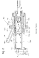
- the Fig. 2 shows an axial sectional view of another known pressure medium cylinder 110 with a tracking device, which is designed here as a master cylinder for a hydraulic actuator for actuating a motor vehicle clutch.
- the master cylinder 110 includes as in Fig. 1 Slave cylinder 10 shown a plastic housing 112 having a front portion 114a and a rear portion 114b having stepped bore and with a pressure port 116 for connection to a hydraulic slave cylinder.
- a manufactured with a through hole 118a guide sleeve 118 is inserted and connected to engage a formed on this and the housing 112, not graphically visible locking means and connected so that it is fixed axially in both directions on the housing 112.
- the piston 122 of the master cylinder 110 is connected via a pivotally arranged on this piston rod 134 with a clutch pedal, not shown in operative connection, upon actuation, the piston 122 moves in the figure to the left and via the fluid connection to the slave cylinder and a connected thereto Clutch fork for disengaging the vehicle clutch controls.
- a follower port 150 From the lateral surface of the housing 112 is from a follower port 150, which can communicate with a running therein run-off channel 150a with a drawing here not shown fluid supply tank.
- the secondary seal 126 can also be arranged directly in the housing 112 and also also abut the piston 122 and the guide tube 118.
- the spacing element 152 rests on the piston except for fluid channels provided therein, so that reliable guidance of the piston 122 is ensured in this section as well.
- another sealing element 156 manufactured as an O-ring seal is used to seal the overflow space 154.
- follower means are on the piston running surface in the form of an open compensating or follower grooves 158 extending in the axial direction from its end face. The extent is selected so that the primary seal 127 is bridged in the illustrated end position of the piston 122 and a compensation channel is released starting from the pressure chamber 124 via the Nachlaufnuten 158 to the follow-up space 154 and further to the follower passage 150 a.
- the fluid connection between the follow-up space 154 and the trailing channel 150 a and the pressure chamber 124 is through in the Fig. 3 concealed axial channels in the intermediate ring or spacer 152 ensured.
- the follower groove 158 is moved out of the area of the primary seal 127, whereby the primary seal 127 completely engages the piston running surface and thus interrupts the connection between the pressure chamber 124 and the follower passage 150a.
- the follower means can also be performed at the position shown as a closed groove, ie essentially as an axial bore, which is connected to a radially outwardly guided lateral bore, ie a branch channel.
- the branch canal then flows into the in Fig. 2 shown piston position directly behind the cooperating with the piston 122 sealing lip 127b of the primary seal 127 in the follow-up space 154.
- In the upper wall of the pressure chamber 124 is in support of the vent a rising in the direction of the primary seal 127 vent groove 1 58 arranged.
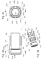
- Fig. 3 shows a guide sleeve 218, which can be connected by means of latching hooks 220 fixed to the housing 112.
- latching hooks 220 fixed to the housing 112.
- the locking hooks 220 in corresponding thereto on the cylinder housing of the pressure cylinder after Fig. 2 trained, but there not graphically engage window.
- a plurality of circumferentially spaced axial projections 222a-e are formed in the radially outer region, which act as a spacer element 252 for spacing the primary 127 and the secondary seal 126. It can be seen that the distance between the in the Fig. 3 Upwardly located axial projections 222a, b is made larger compared to the other distances, whereby a recess 222f is formed.
- the sealing package 225 shown in extension of the axial projections 222a-e comprises a primary 227, a secondary seal 226 and a sealing bead 256 formed on the latter, which function as the ring seal 156 according to FIG Fig. 2 takes over.
- the sealing package 225 is produced by molding an elastomer, for example EPDM, on the guide sleeve 218, in particular in the region of the axial projections 222a-e provided there.
- the seal pack 225 has been shown separately from the guide sleeve 218 for ease of illustration.
- the axial projections 222a-e become contiguous Elastomer part radially encapsulated on both sides, wherein the elastomer langlochfömige recesses 223 penetrates the axial projections 222a-e.
- the assembly 218, 225 produced in this way is in Fig. 3b in a longitudinal and in Fig. 3c shown in a cross section.
- the molded elastomer body 225 includes a primary seal portion 227 having a radially outer seal lip 227a and an inner radial seal lip 227b, and further a secondary seal portion 226 having an outer bead 256 and an inner seal lip 226b.
- the formerly outer sealing lip 126a of the seal 126 in FIG Fig. 2 is extended to a pipe section 228 and thus forms the base portion of the primary seal 227.
- the pipe section 228 has over a peripheral region on an approximately slot-shaped recess 228a, which coincides with the recess 222f on the guide sleeve 218 or is arranged there.
- the recess 228a is thus part of the follow-up space for trailing fluid in the pressure fluid cylinder.
- radially inwardly directed sections that terminate on a common pitch circle with the diameter of the bushing can additionally be provided.
- molded onto the guide sleeve 218 seal package 225 this can also be prepared separately in advance and arranged on the guide sleeve 318, more precisely the distance element executed there 352, as in the 4a-c shown.
- the axial projections 322a-d for forming the spacer element 352 are again in this case as already described above formed with gaps, but recesses 223 (FIG. 3a-c ) within the axial projections 322a-d are not performed here.
- At the seal package 325 are corresponding to the axial projections 322a-e, in the Fig. 4a formed concealed pockets, in which the axial projections 322a-e engage when pushing the seal package 325.
- the Fig. 4b, c show in addition to an axial and a radial section, with the same or equivalent parts with a respect to the Fig. 3a-c in the first place, change from "2" to "3".
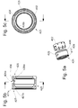
- Fig. 5a-c is shown as a further variant of a sealing packet 325 a separately manufactured from the guide sleeve, annular spacer element 452, which is encapsulated to form a primary 327 and a secondary seal 426 of an elastomeric material.
- the reference numerals of the others, to the Fig. 3 . 4 the same or equivalent parts have been changed to "4" in the first digit. It results from this construction, the advantage that for different types of pressure fluid cylinders, the same seal package can be used, whereas the housing and the guide sleeve can be adapted to the particular application.
- this spacer element in the master cylinder according to Fig. 2 is there only the guide sleeve 118 in the region of the secondary seal 126 to modify.
Landscapes
- Engineering & Computer Science (AREA)
- General Engineering & Computer Science (AREA)
- Mechanical Engineering (AREA)
- Physics & Mathematics (AREA)
- Fluid Mechanics (AREA)
- Transportation (AREA)
- Hydraulic Clutches, Magnetic Clutches, Fluid Clutches, And Fluid Joints (AREA)
- Transmission Of Braking Force In Braking Systems (AREA)
- Actuator (AREA)
- Sealing Devices (AREA)
- Fluid-Damping Devices (AREA)
Abstract
Description
- Die Erfindung betrifft einen Druckmittelzylinder für ein hydraulisches Betätigungssystem eines Kraftfahrzeuges. Ein gemäß dem Oberbegriff des Patentanspruchs 1 definierter Druckmittelzylinder wird üblicherweise als Nehmerzylinder und ein gemäß dem Oberbegriff des Patentanspruchs 2 definierter Druckmittelzylinder wird üblicherweise als Geberzylinder für ein hydraulisches Kupplungs- oder Bremssystem eines Kraftfahrzeuges eingesetzt. Solche Druckmittelzylinder sind beispielsweise aus der
DE 103 52 941 A1 bzw. derEP 1 602 544 A1 bekannt. - In der
DE 196 80 491 B4 wird ein weiterer gattungsgemäßer Geberzylinder beschrieben, bei dem die Primärdichtung zur Abdichtung des Druckraumes, ein Abstandselement und eine von diesem axial zur Primärdichtung beabstandete Sekundärdichtung zur Abdichtung eines Nachlaufraumes als gemeinsame Baueinheit ausgeführt sind. Dazu können diese Dichtungen axial beabstandet werkstoffschlüssig mit dem Abstandselement verbunden sein, oder gemeinsam als ein einziges Elastomerteil gefertigt sein, welches mit dem Abstandselement stoffschlüssig verbunden ist oder dieses bereits selbst mit ausbildet. - Es ist ersichtlich, dass das Dichtungssystem derartiger Druckmittelzylinder zur Abdichtung des Druckraumes und bei einem Geberzylinder zusätzlich eines Nachlaufraumes gegenüber der Umgebung eine Mehrzahl von Bauteilen erfordert, welche einen beträchtlichen Montageaufwand zur Folge haben, wobei auch das Risiko einer Fehlmontage durch fehlerhaft eingelegte Bauteile existiert. Auch bei dem mit der
DE 196 80 491 B4 offenbarten Dichtungsanordnung eines Druckmittelzylinders ist eine Fehlmontage infolge eines um 180° gedrehten Dichtungspakets nicht auszuschließen. - Von dieser Problematik ausgehend, stellt sich die Erfindung die Aufgabe, Druckmittelzylinder mit einem vereinfachten und montagesicheren Aufbau bereitzustellen.
- Diese Aufgabe wird bei den Druckmittelzylindern der eingangs genannten Art durch die im Kennzeichen der Patentansprüche 1 und 2 genannten Merkmale gelöst.
- Es wird somit ein erster Druckmittelzylinder für ein hydraulisches Betätigungssystem eines Kraftfahrzeuges vorgeschlagen, welcher ein Gehäuse mit einem Innenzylinder und mit einem Druckanschluss umfasst und weiter eine mit dem Gehäuse fest verbundene Führungshülse, die mit dem Innenzylinder des Gehäuses eine gemeinsame Laufbuchse ausbildet und einen in der Laufbuchse verschiebbar angeordneten Kolben, der einen variablen Druckraum begrenzt. Zur Abdichtung des Druckraumes dient eine gehäusefeste erste Dichtung, die mit dem Kolben und mit dem Gehäuse oder mit einem mit dem Gehäuse fest verbundenen Bauteil zusammenwirkt. Der Druckmittelzylinder zeichnet sich erfindungsgemäß dadurch aus, dass die erste Dichtung stoffschlüssig mit der Führungshülse ausgeführt ist.
- Die stoffschlüssige Verbindung von Führungshülse und der aus einem Elastomerwerkstoff gefertigten Dichtung erfolgt vor der Montage des Druckmittelzylinders z.B. mittels Verkleben, Anvulkanisieren oder durch Anspritzen eines Elastomers an die Führungshülse. Auf diese Weise wird die Teileanzahl eines Druckmittelzylinders reduziert und ein diesbezüglicher Montagefehler ausgeschlossen.
- Es wird weiterhin ein zweiter Druckmittelzylinder für ein hydraulisches Betätigungssystem eines Kraftfahrzeuges vorgeschlagen, welcher ein Gehäuse mit einem Innenzylinder und mit einem Druckanschluss umfasst, weiter eine mit dem Gehäuse fest verbundene Führungshülse, die mit dem Innenzylinder des Gehäuses eine gemeinsame Laufbuchse ausbildet und einen in der Laufbuchse verschiebbar angeordneten Kolben, der einen variablen Druckraum begrenzt. Zur Abdichtung des Druckraumes dient eine gehäusefeste erste Dichtung, die mit dem Kolben und mit dem Gehäuse oder mit einem mit dem Gehäuse fest verbundenen Bauteil zusammenwirkt. Zusätzlich umfasst der Druckmittelzylinder eine zwischen dem Kolben und dem Gehäuse wirkende zweite gehäusefeste Dichtung, die von der ersten Dichtung durch ein Abstandselement axial beabstandet angeordnet ist. Der Druckmittelzylinder ist dadurch gekennzeichnet, dass das Abstandselement als Bestandteil der Führungshülse ausgeführt ist.
- Das Abstandselement kann beispielsweise als ringförmiger Axialfortsatz der Führungshülse oder in Form segmentierter Axialvorsprünge ausgebildet sein. Für die Verwendung als Geberzylinder können dabei vorteilhaft durch entsprechende Aussparungen Fluidkanäle zum Nachströmen von Fluid aus einem mit dem Druckmittelzylinder verbundenen Vorratsbehälter und zur möglichst flächigen Umströmung bzw. Benetzung des Kolbens vorgesehen sein.
- Durch die vorgeschlagene Ausgestaltung wird die Anzahl der für einen Druckmittelzylinder zu montierenden Bauteile reduziert. Mit einer einteiligen Gestaltung von Führungshülse und Abstandselement entfallen damit auch gleichzeitig Montagefehler durch eine fehlerhafte gegenseitige Lage und Positionierungenauigkeiten der vormals separat vorliegenden Teile.
- Die Primär- und die Sekundärdichtung können als Einzeldichtungen bereits vor der Montage im Gehäuse des Druckmittelzylinders an der um das Abstandselement verlängerten Führungshülse angeordnet werden. Dazu können an der Führungshülse zwei axial beabstandete und radial gestaffelte Aufnahmeabschnitte zur Anordnung der Primär- und der Sekundärdichtung vorgesehen sein. Zum Beispiel kann der Aufnahmeabschnitt der Primärdichtung an dem freien Ende des Abstandselementes vorgesehen sein, wohingegen zur Anordnung der Sekundärdichtung ein zum Abstandselement radial innenliegender und axial kürzerer Aufnahmeabschnitt vorgesehen ist. Beim Zusammenführen dieser Baueinheit mit dem Zylindergehäuse und dem Kolben ist das Risiko eines unentdeckten Montagefehlers infolge einer falsch eingelegten Dichtung merklich reduziert, da die gesamte Dichtungsanordnung bereits vor deren Einbau auf Mängel geprüft werden kann.
- Vorteilhafte Ausgestaltungen und Weiterbildungen der Erfindung sind durch die Merkmale der abhängigen Ansprüche angegeben.
- Gemäß einer vorteilhaften Weiterbildung ist vorgesehen, an dem Abstandselement einen Führungsabschnitt für den Kolben auszubilden. Damit kann die Führung des Kolbens über einen größeren Abschnitt erfolgen. Die einteilige Ausgestaltung ermöglicht hierbei eine exakte, in axialer Richtung lediglich von der Primär- und Sekundärdichtung unterbrochene Führungsfläche für den Kolben.
- Gemäß einer besonders bevorzugten Variante ist vorgesehen, dass zumindest eine von Primär- und Sekundärdichtung stoffschlüssig mit der Führungshülse ausgeführt ist, beispielsweise mittels einer Verklebung, durch Anvulkanisieren oder durch Anspritzen eines Elastomers an die Führungshülse bzw. an das Abstandselement. Wenn sowohl die Primär- als auch die Sekundärdichtung stoffschlüssig mit der Führungshülse verbunden sind, wird somit eine komplette Dichtungskartusche zum unmittelbaren Einbau in das Zylindergehäuse bereitgestellt, wodurch das Handling einzelner Dichtungen entfällt und die Montage eines Druckmittelzylinders noch weiter vereinfacht wird.
- Alternativ dazu können die erste und die zweite Dichtung auch als gemeinsamer Verbund zur Montage an der Führungshülse ausgeführt werden, sodass anstelle von bisher zwei Einzeldichtungen ein einziges, die Primär- und die Sekundärdichtung umfassendes Dichtungspaket vorliegt. Beim Montagevorgang selbst erweist es sich als günstig, zunächst den Kolben durch die Führungshülse durchzuführen, dann das Dichtungspaket zunächst auf den Kolben und weiter auf das an der Führungshülse angeformte Abstandselement zu schieben.
- Bei einem mit einer Führungshülse ausgeführten Druckmittelzylinder ist üblicherweise zwischen dem Gehäuse und der Führungshülse eine weitere, dritte gehäusefeste Dichtung vorgesehen, welche z.B. wie in der
EP 1 602 544 A1 separat ausgeführt ist. Bei dieser Variante ist es von Vorteil, die dritte Dichtung stoffschlüssig mit der Führungshülse z.B. mittels Anspritzen auszuführen, so dass sich eine separate Dichtung erübrigen kann. - Gemäß einer besonders bevorzugten Ausgestaltung wird die dritte Dichtung in Baueinheit mit der ersten Dichtung ausgeführt, wobei bei einer Ringlippendichtung die radial außen liegende Dichtlippe bzw. der dort befindliche Dichtungsabschnitt ggf. mit einer zusätzlichen Dichtwulst am Zylindergehäuse ausgeführt werden kann und wobei die radial innenliegende Dichtlippe am Kolben und der die Dichtlippen verbindende Basisabschnitt an der Führungshülse anliegen kann.
- Nachfolgend wird die Erfindung mit Bezug auf die anliegenden Figuren beispielhaft beschrieben.
- Es zeigen:
- Fig. 1
- einen Nehmerzylinder bekannter Bauart;
- Fig. 2
- einen Geberzylinder bekannter Bauart;
- Fig. 3a-c
- eine gemäß der vorliegenden Erfindung gestaltete Führungshülse mit einem daran ausgeführten segmentierten Abstandselement und einem angespritzten Dichtungselement zum Einbau in den Geberzylinder nach
Fig. 2 ; - Fig. 4a-c
- eine gemäß der vorliegenden Erfindung gestaltete Führungshülse mit einem daran ausgeführten segmentierten Abstandselement und einem separaten Dichtungselement zum Einbau in den Geberzylinder nach
Fig. 2 ; - Fig. 5a-c
- ein Abstandselement mit einem angespritzten Dichtungselement zum Einbau in den Geberzylinder nach
Fig. 2 . -
Fig. 1 zeigt einen an sich bekannten, als Nehmerzylinder ausgebildeten Druckmittelzylinder 10 für ein hydraulisches Betätigungssystem eines Kraftfahrzeuges. Der Nehmerzylinder 10 umfasst ein Kunststoffgehäuse 12 mit einer Stufenbohrung, welche einen vorderen Abschnitt 14a und einen hinteren Abschnitt 14b aufweist und wobei an dem Gehäuse 12 ein Druckanschluss 16 zur Verbindung mit einem hydraulischen Geberzylinder ausgebildet ist. In dem hinteren Abschnitt 14b der Stufenbohrung ist eine mit einer Durchgangsbohrung 18a gefertigte Führungshülse 18 bis zum gegenseitigen Eingriff von an dieser und dem Gehäuse 12 ausgebildeten hakenförmigen Anschlagelementen 20a, b eingeführt und fest verrastet, wobei im zusammengebauten Zustand die beiden Innenzylinder der Bohrungen 14a, 18a eine gemeinsame innere Laufbuchse für einen darin verschiebbar angeordneten Kolben 22 ausbilden. Somit ergibt sich innerhalb des Nehmerzylinders 10 ein von dem Kolben 22 und von der Innenwandung des Gehäuses 12 begrenzter variabler Druckraum 24. - Zur Abdichtung des Druckraumes 24 gegenüber der Umgebung dient eine an einem Absatz 12a des Gehäuses 12 im Bereich der Durchmesserstufe angeordnete Ringlippendichtung 26, die mit einer radial inneren Dichtlippe 26a am Kolben 22 und mit einer radial äußeren Dichtlippe 26b Gehäuse 12 anliegt. Ein, beide Dichtlippen 26a, 26b verbindender Basisbereich 26c liegt an der Führungshülse 18 an, so dass auch ein zwischen dem Gehäuse 12 und der Führungshülse 18 verbleibender Ringspalt gegenüber dem Druckraum 24 sicher abgedichtet ist.
- Der Kolben 22 weist eine als Tiefziehteil ausgebildete, einseitig mit einem Boden 28a ausgeführte metallische Kolbenschafthülse 28 auf, von der ein aus Kunststoff gefertigtes Einsatzteil 30 aufgenommen ist. Mit dem Kolben 22 ist über eine als Kugelpfanne 32 an dem Einsatzteil 30 ausgeführte Aufnahmeanordnung schwenkbeweglich eine Kolbenstange 34 mit einer Kugelkalotte 34a verbunden, welche mit einer nicht dargestellten Kupplungsgabel oder dergleichen und weiteren Ausrückmitteln einer Fahrzeugkupplung in Wirkverbindung gebracht werden kann. Der Nehmerzylinder 10 weist weiterhin einen seitlich an dessen Gehäuse 12 angeordneten Flansch 36 zur Aufnahme eines zeichnerisch nicht dargestellten Entlüftungsventils auf.
- Gemäß der vorliegenden Erfindung ist vorgesehen, bei dem in
Fig. 1 dargestellten Druckmittelzylinder 10, die Ringlippendichtung 26 stoffschlüssig durch Anspritzen eines Elastomermaterials mit der Führungshülse 18 auszuführen. Das auf diese Weise geschaffene Verbundbauteil 18, 26 ersetzt damit die separate Ringlippendichtung 26 und die separate Führungshülse 18, wobei der Druckmittelzylinder 10 ansonsten unverändert beibehalten werden kann. - Die
Fig. 2 zeigt eine Axialschnittdarstellung eines weiteren bekannten Druckmittelzylinders 110 mit einer Nachlaufeinrichtung, welcher hier als Geberzylinder für eine hydraulische Betätigungseinrichtung zur Betätigung einer Kraftfahrzeugkupplung ausgebildet ist. Der Geberzylinder 110 umfasst wie der inFig. 1 gezeigte Nehmerzylinder 10 ein Kunststoffgehäuse 112 mit einer einen vorderen Abschnitt 114a und einen hinteren Abschnitt 114b aufweisenden Stufenbohrung und mit einem Druckanschluss 116 zur Verbindung mit einem hydraulischen Nehmerzylinder. In den hinteren Abschnitt 114b der Stufenbohrung ist eine mit einer Durchgangsbohrung 118a gefertigte Führungshülse 118 bis zum Eingriff einer an dieser und dem Gehäuse 112 ausgebildeten, hier zeichnerisch nicht sichtbaren Rastmitteln eingeführt und verbunden, so dass diese axial in beiden Richtungen am Gehäuse 112 festgelegt ist. Im zusammengebauten Zustand bilden die beiden Innenzylinder der Bohrungen 114a, 118a eine gemeinsame innere Laufbuchse für einen darin verschiebbar angeordneten Kolben 122 aus. Somit ergibt sich innerhalb des Geberzylinders 110 ein von dem Kolben 122 und von der Innenwandung des Gehäuses 112 begrenzter variabler Druckraum 124. - Der Kolben 122 des Geberzylinders 110 steht über eine schwenkbeweglich an diesem angeordnete Kolbenstange 134 mit einem nicht dargestellten Kupplungspedal in Wirkverbindung, bei dessen Betätigung sich der Kolben 122 in der Figur nach links verschiebt und über die Fluidverbindung den Nehmerzylinder und eine mit diesen verbundene Kupplungsgabel zum Ausrücken der Fahrzeugkupplung steuert. Von der Mantelfläche des Gehäuses 112 steht ein Nachlaufanschluss 150 ab, der mit einem darin ausgeführten Nachlaufkanal 150a mit einem hier zeichnerisch nicht dargestellten Fluid-Nachlaufbehälter kommunizieren kann.
- Zur Abdichtung des Druckraumes 124 und eines Nachlaufraumes sind am Gehäuse zwei, durch ein als Zwischenring 152 ausgeführtes Abstandselement beabstandete Ringlippendichtungen 126, 127 angeordnet, die jeweils mit einer äußeren Dichtlippe 126a, 127a an der Führungshülse 118 bzw. am Gehäuse 112 und mit einer zweiten inneren Dichtlippe 126b, 127b an der Lauffläche des Kolbens 122 anliegen. Die an einem Gehäuseabsatz 112a anliegende Primärdichtung 127 dichtet den Druckraum 124 gegenüber dem durch den Zwischenring 152 gebildeten Nachlaufraum 154 ab. Die am Ende des Führungsrohres 118 in eine Stufe 118b eingesetzte Sekundärdichtung 126 dient der dichten Abtrennung des Nachlaufraumes 154 von der Atmosphäre. Alternativ kann die Sekundärdichtung 126 auch unmittelbar im Gehäuse 112 angeordnet werden und zudem gleichfalls am Kolben 122 und am Führungsrohr 118 anliegen. Das Abstandselement 152 liegt bis auf darin vorgesehene Fluidkanäle am Kolben an, so dass auch in diesem Abschnitt eine sichere Führung des Kolbens 122 gewährleistet ist. Zwischen der Führungshülse 118 und dem Gehäuse 112 ist zur Abdichtung des Nachlaufraumes 154 ein weiteres, als O-Ringdichtung gefertigtes Dichtelement 156 eingesetzt.
- Um ein Nachlaufen von Hydraulikflüssigkeit in den und das Entweichen von Gasblasen aus dem Druckraum 124 sicherzustellen, sind an der Kolbenlauffläche Nachlaufmittel in Form einer sich von dessen Stirnseite aus in axialer Richtung erstreckenden offenen Ausgleichs- bzw. Nachlaufnuten 158 angeordnet. Die Erstreckung ist so gewählt, dass die Primärdichtung 127 in der dargestellten Endstellung des Kolbens 122 überbrückt wird und ein Ausgleichskanal vom Druckraum 124 ausgehend über die Nachlaufnuten 158 zum Nachlaufraum 154 und weiter zum Nachlaufkanal 150a freigegeben wird. Die Fluidverbindung zwischen dem Nachlaufraum 154 und dem Nachlaufkanal 150a sowie dem Druckraum 124 wird durch in der
Fig. 3 verdeckte axiale Kanäle im Zwischenring bzw. Abstandselement 152 sichergestellt. Bei einer Bewegung des Kolbens 122 in die den Druckraum 124 verkleinernde Richtung wird die Nachlaufnut 158 aus dem Bereich der Primärdichtung 127 herausbewegt, wodurch sich die Primärdichtung 127 vollständig an die Kolbenlauffläche anlegt und damit die Verbindung zwischen dem Druckraum 124 und dem Nachlaufkanal 150a unterbricht. Anstelle einer offen Nut 158 können die Nachlaufmittel auch an der gezeigten Position als geschlossene Nut, d.h. im wesentlichen als Axialbohrung ausgeführt werden, welche mit einer nach radial außen geführten seitlichen Bohrung, d.h. einem Stichkanal verbunden ist. Der Stichkanal mündet dann in der inFig. 2 gezeigten Kolbenstellung unmittelbar hinter der mit dem Kolben 122 zusammenwirkenden Dichtlippe 127b der Primärdichtung 127 in den Nachlaufraum 154. In der oberen Wandung des Druckraums 124 ist zur Unterstützung der Entlüftung eine sich in Richtung der Primärdichtung 127 ansteigende Entlüftungsnut 1 58 angeordnet. - Anhand der weiteren Figuren wird nachfolgend auf der Basis des mit
Fig. 2 dargestellten Druckmittelzylinders erläutert, wie die dort separat ausgeführten Ringlippendichtungen 126, 127, die O-Ringdichtung 156, das Abstandselement 152 und die Führungshülse 118 zur Vereinfachung des Aufbaus modifiziert werden können, wobei alle anderen Bauteile des Druckmittelzylinders 110 von deren grundlegenden Gestaltung unverändert übernommen werden können. -
Fig. 3 zeigt eine Führungshülse 218, die mittels Rasthaken 220 fest mit dem Gehäuse 112 verbunden werden kann. Zu diesem Zweck können die Rasthaken 220 in dazu korrespondierend am Zylindergehäuse des Druckmittelzylinders nachFig. 2 ausgebildete, dort jedoch zeichnerisch nicht dargestellte Fenster eingreifen. An dem zum Druckraum 124 ausgerichteten Ende sind im radial äußeren Bereich mehrere, am Umfang beabstandete Axialvorsprünge 222a-e ausgebildet, welche als Abstandselement 252 zur Beabstandung von Primär- 127 und Sekundärdichtung 126 wirken. Es ist erkennbar, dass der Abstand zwischen den in derFig. 3 oben befindlichen Axialvorsprüngen 222a, b gegenüber den weiteren Abständen vergrößert ausgeführt ist, wodurch eine Aussparung 222f gebildet wird. - Das in Verlängerung der Axialvorsprünge 222a-e dargestellte Dichtungspaket 225 umfasst eine Primär- 227, eine Sekundärdichtung 226 und einen an letzterer ausgebildeten Dichtwulst 256, der die Funktion der Ringdichtung 156 gemäß
Fig. 2 übernimmt. Das Dichtungspaket 225 wird durch Anspritzen eines Elastomers, z.B. EPDM, an die Führungshülse 218, insbesondere im Bereich der dort vorgesehenen Axialvorsprünge 222a-e erzeugt. InFig. 3 wurde das Dichtungspaket 225 lediglich zur besseren Veranschaulichung separat von der Führungshülse 218 dargestellt. Beim Spritzvorgang werden die Axialvorsprünge 222a-e zur Bildung eines zusammenhängenden Elastomerteils radial beidseitig umspritzt, wobei das Elastomer langlochfömige Ausnehmungen 223 an den Axialvorsprüngen 222a-e durchdringt. - Die auf diese Weise erzeugte Baueinheit 218, 225 ist in
Fig. 3b in einem Längs- und inFig. 3c in einem Querschnitt abgebildet. Der angespritzte Elastomerkörper 225 umfasst einen Primärdichtungsbereich 227 mit einer radial äußeren Dichtlippe 227a und einer inneren radial Dichtlippe 227b und des Weiteren einen Sekundärdichtungsbereich 226 mit einer Außenwulst 256 und einer inneren Dichtlippe 226b. Die vormals äußere Dichtlippe 126a der Dichtung 126 inFig. 2 ist zu einem Rohrabschnitt 228 verlängert und bildet damit den Basisabschnitt der Primärdichtung 227. Der Rohrabschnitt 228 weist über einen Umfangsbereich eine etwa schlitzförmige Ausnehmung 228a auf, welche mit der Aussparung 222f an der Führungshülse 218 zusammenfällt bzw. dort angeordnet ist. Die Ausnehmung 228a ist somit Teil des Nachlaufraumes für in den Druckmittelzylinder nachlaufendes Fluid. - Zur Führung des Kolbens im Bereich des Abstandselements 252 können zusätzlich an diesem radial nach innen gerichtete Abschnitte, die auf einem gemeinsamen Teilkreis mit dem Durchmesser der Laufbuchse enden, vorgesehen werden.
- Alternativ zu dem mit den
Fig. 3a-c dargestellten, an die Führungshülse 218 angespritzten Dichtungspaket 225 kann dieses auch vorab separat hergestellt und an der Führungshülse 318, genauer dem dort ausgeführten Abstandselement 352 angeordnet werden, wie in denFig.4a-c gezeigt. Die Axialvorsprünge 322a-d zur Bildung des Abstandselementes 352 sind in diesem Fall wiederum wie bereits vorstehend beschrieben mit Zwischenräumen ausgebildet, wobei jedoch Ausnehmungen 223 (Fig.3a-c ) innerhalb der Axialvorsprünge 322a-d hierbei nicht ausgeführt sind. An dem Dichtungspaket 325 sind zu den Axialvorsprüngen 322a-e korrespondierende, in derFig. 4a verdeckte Taschen ausgebildet, in welche beim Aufschieben des Dichtungspakets 325 die Axialvorsprünge 322a-e eingreifen. DieFig. 4b,c zeigen dazu ergänzend einen Axial- und einen Radialschnitt, wobei gleiche oder gleichwirkende Teile mit einer gegenüber denFig. 3a-c an der ersten Stelle von "2" auf "3" geänderte Bezugsziffer tragen. - In
Fig. 5a-c ist als weitere Variante eines Dichtungspakets 325 ein von der Führungshülse separat gefertigtes, ringförmiges Abstandselement 452 dargestellt, welches zur Bildung einer Primär- 327 und einer Sekundärdichtung 426 von einem Elastomermaterial umspritzt ist. Die Bezugsziffern der weiteren, zu denFig. 3 ,4 gleichen bzw. gleichwirkenden Teile wurden in der ersten Stelle in "4" geändert. Es ergibt sich durch diese Bauweise der Vorteil, dass für verschiedene Typen von Druckmittelzylindern das gleiche Dichtungspaket verwendet werden kann, wohingegen das Gehäuse und die Führungshülse an den jeweiligen Anwendungsfall angepasst werden können. Zu einem Einbau dieses Abstandselementes in den Geberzylinder gemäßFig. 2 ist dort lediglich die Führungshülse 118 im Bereich der Sekundärdichtung 126 zu modifizieren.
Claims (7)
- Druckmittelzylinder (10) für ein hydraulisches Betätigungssystem eines Kraftfahrzeuges umfassend- ein Gehäuse (12) mit einem Innenzylinder (14a) und mit einem Druckanschluss (16),- eine mit dem Gehäuse (12) fest verbundene Führungshülse (18), die mit dem Innenzylinder (14a) des Gehäuses (12) eine gemeinsame Laufbuchse ausbildet,- einen in der Laufbuchse verschiebbar angeordneten Kolben (22), der einen variablen Druckraum (24) begrenzt,- eine gehäusefeste erste Dichtung (26), die mit dem Kolben (24) und mit dem Gehäuse (12) oder mit einem mit dem Gehäuse (12) fest verbundenen Bauteil (18) zusammenwirkt,dadurch gekennzeichnet,
dass die erste Dichtung (26) stoffschlüssig mit der Führungshülse (18) ausgeführt ist (Fig. 1). - Druckmittelzylinder (110) nach dem Oberbegriff von Patentanspruch 1, wobei dieser eine zwischen dem Kolben (122) und dem Gehäuse (112) wirkende zweite gehäusefeste Dichtung (127) umfasst, die von der ersten Dichtung (126) durch ein Abstandselement (152) axial beabstandet angeordnet ist (Fig. 2),
dadurch gekennzeichnet,
dass das Abstandselement (252) als Bestandteil der Führungshülse (218) ausgeführt ist (Fig. 3). - Druckmittelzylinder nach Anspruch 2,
dadurch gekennzeichnet,
dass das Abstandselement einen Führungsabschnitt für den Kolben aufweist. - Druckmittelzylinder nach Anspruch 2 oder 3,
dadurch gekennzeichnet,
dass zumindest eine der Dichtungen (226; 227) stoffschlüssig mit der Führungshülse ausgeführt ist (Fig. 3). - Druckmittelzylinder nach Anspruch 2, oder 3,
dadurch gekennzeichnet,
dass die erste (326) und die zweite Dichtung (327) als gemeinsamer Verbund (325) zur Montage an der Führungshülse (318) ausgeführt sind (Fig. 4). - Druckmittelzylinder nach einem der vorhergehenden Ansprüche, wobei dieser eine zwischen dem Gehäuse (112) und der Führungshülse (118) angeordnete dritte gehäusefeste Dichtung (156) aufweist (Fig. 2),
dadurch gekennzeichnet,
dass die dritte Dichtung (356) stoffschlüssig mit der Führungshülse (318) ausgeführt ist (Fig. 4). - Druckmittelzylinder nach einem der vorhergehenden Ansprüche ,
dadurch gekennzeichnet,
dass die dritte Dichtung (356) in Baueinheit mit der ersten Dichtung (326) ausgeführt ist (Fig. 4).
Applications Claiming Priority (1)
| Application Number | Priority Date | Filing Date | Title |
|---|---|---|---|
| DE102008011132A DE102008011132A1 (de) | 2008-02-26 | 2008-02-26 | Druckmittelzylinder für ein hydraulisches Betätigungssystem eines Kraftfahrzeuges |
Publications (3)
| Publication Number | Publication Date |
|---|---|
| EP2096009A2 true EP2096009A2 (de) | 2009-09-02 |
| EP2096009A3 EP2096009A3 (de) | 2010-12-22 |
| EP2096009B1 EP2096009B1 (de) | 2011-07-20 |
Family
ID=40459729
Family Applications (1)
| Application Number | Title | Priority Date | Filing Date |
|---|---|---|---|
| EP09153199A Not-in-force EP2096009B1 (de) | 2008-02-26 | 2009-02-19 | Druckmittelzylinder für ein hydraulisches Betätigungssystem eines Kraftfahrzeuges |
Country Status (3)
| Country | Link |
|---|---|
| EP (1) | EP2096009B1 (de) |
| AT (1) | ATE517004T1 (de) |
| DE (1) | DE102008011132A1 (de) |
Families Citing this family (2)
| Publication number | Priority date | Publication date | Assignee | Title |
|---|---|---|---|---|
| DE102012021077A1 (de) * | 2012-10-19 | 2014-04-24 | Geräte- und Pumpenbau GmbH | Dichtungseinrichtung für Stangen |
| DE102020112629A1 (de) | 2020-05-11 | 2021-11-11 | Schaeffler Technologies AG & Co. KG | Geberzylinder |
Citations (3)
| Publication number | Priority date | Publication date | Assignee | Title |
|---|---|---|---|---|
| DE10352941A1 (de) | 2003-11-11 | 2005-06-09 | Zf Friedrichshafen Ag | Druckmittelzylinder für eine hydraulische Betätigunseinrichtung |
| EP1602544A1 (de) | 2004-06-04 | 2005-12-07 | Zf Friedrichshafen Ag | Hydraulikzylinder |
| DE19680491B4 (de) | 1995-06-27 | 2006-09-21 | Luk Lamellen Und Kupplungsbau Beteiligungs Kg | Abdichtungen in einem Geberzylinder |
Family Cites Families (3)
| Publication number | Priority date | Publication date | Assignee | Title |
|---|---|---|---|---|
| GB1009261A (en) * | 1961-10-17 | 1965-11-10 | Automotive Prod Co Ltd | Improvements in and relating to fluid pressure master cylinders |
| US7219495B2 (en) * | 2004-06-04 | 2007-05-22 | Zf Friedrichshafen Ag | Hydraulic cylinder |
| DE102006030450A1 (de) * | 2006-06-29 | 2008-01-03 | Fte Automotive Gmbh | Hydraulische Stellvorrichtung für die Betätigung einer Schaltstange insbesondere eines Schaltgetriebes für Kraftfahrzeuge |
-
2008
- 2008-02-26 DE DE102008011132A patent/DE102008011132A1/de not_active Withdrawn
-
2009
- 2009-02-19 AT AT09153199T patent/ATE517004T1/de active
- 2009-02-19 EP EP09153199A patent/EP2096009B1/de not_active Not-in-force
Patent Citations (3)
| Publication number | Priority date | Publication date | Assignee | Title |
|---|---|---|---|---|
| DE19680491B4 (de) | 1995-06-27 | 2006-09-21 | Luk Lamellen Und Kupplungsbau Beteiligungs Kg | Abdichtungen in einem Geberzylinder |
| DE10352941A1 (de) | 2003-11-11 | 2005-06-09 | Zf Friedrichshafen Ag | Druckmittelzylinder für eine hydraulische Betätigunseinrichtung |
| EP1602544A1 (de) | 2004-06-04 | 2005-12-07 | Zf Friedrichshafen Ag | Hydraulikzylinder |
Also Published As
| Publication number | Publication date |
|---|---|
| DE102008011132A1 (de) | 2009-08-27 |
| EP2096009B1 (de) | 2011-07-20 |
| ATE517004T1 (de) | 2011-08-15 |
| EP2096009A3 (de) | 2010-12-22 |
Similar Documents
| Publication | Publication Date | Title |
|---|---|---|
| WO2013076146A2 (de) | Hauptzylinder | |
| EP3478969B1 (de) | Geberzylinder, insbesondere für eine hydraulische kupplungsbetätigungsvorrichtung in kraftfahrzeugen | |
| DE102008063241A1 (de) | Hauptzylinder | |
| EP2566730B1 (de) | Hauptzylinder für eine hydraulische kraftfahrzeugbremsanlage | |
| EP1162119A1 (de) | Kolben für einen Hydraulikzylinder | |
| EP2096009B1 (de) | Druckmittelzylinder für ein hydraulisches Betätigungssystem eines Kraftfahrzeuges | |
| DE102014223596B4 (de) | Kolben-Zylinder-Anordnung für eine hydraulische Ausrückeinrichtung, insbesondere einen Geberzylinder einer Kupplungsbetätigungseinrichtung | |
| DE102021208531B3 (de) | Geberkolben, hydraulische Fahrzeugbremse und Verfahren zum Herstellen des Geberkolbens | |
| DE102004057137A1 (de) | Hauptzylinder insbesondere für ein geregeltes Bremssystem | |
| EP2836405A1 (de) | Hauptbremszylinderanordnung für eine kraftfahrzeug-bremsanlage sowie integrales dicht-drossel-element hierfür | |
| DE69611890T2 (de) | Verbesserte hydraulische Kupplungsbetätigungsvorrichtung für Kraftfahrzeuge | |
| EP2330005B1 (de) | Hydraulikzylinder | |
| DE19537038B4 (de) | Geberzylinder | |
| DE102011080924A1 (de) | Geberzylinder | |
| EP3177844A1 (de) | Geberzylinder mit führungshülse für dichtlippe des schnüffelsystems | |
| DE69619351T2 (de) | Betätigungszylinder einer hydraulischen Kupplung eines Fahrzeuges | |
| EP3887216B1 (de) | Geberzylinder mit dichtelement | |
| WO2018145691A1 (de) | Geberzylinder mit dichtelement | |
| DE102011102301A1 (de) | Hydraulikzylinder | |
| DE29822705U1 (de) | Geberzylinder für eine Fahrzeughydraulik | |
| DE102014011047A1 (de) | Pneumatisches Zwei-Kreis-Regelventil | |
| DE19653270A1 (de) | Geberzylinder für hydraulische Betätigungssysteme | |
| EP1655192B1 (de) | Unterdruck-Bremskraftverstärker für Kraftfahrzeuge | |
| DE102018009751A1 (de) | Hydraulikzylinder, insbesondere Geber- oder Nehmerzylinder für eine hydraulische Kupplungs- oder Bremsbetätigung für Kraftfahrzeuge | |
| DE10012371C1 (de) | Hauptzylinderanordnung mit Pumpe |
Legal Events
| Date | Code | Title | Description |
|---|---|---|---|
| PUAI | Public reference made under article 153(3) epc to a published international application that has entered the european phase |
Free format text: ORIGINAL CODE: 0009012 |
|
| AK | Designated contracting states |
Kind code of ref document: A2 Designated state(s): AT BE BG CH CY CZ DE DK EE ES FI FR GB GR HR HU IE IS IT LI LT LU LV MC MK MT NL NO PL PT RO SE SI SK TR |
|
| AX | Request for extension of the european patent |
Extension state: AL BA RS |
|
| PUAL | Search report despatched |
Free format text: ORIGINAL CODE: 0009013 |
|
| AK | Designated contracting states |
Kind code of ref document: A3 Designated state(s): AT BE BG CH CY CZ DE DK EE ES FI FR GB GR HR HU IE IS IT LI LT LU LV MC MK MT NL NO PL PT RO SE SI SK TR |
|
| AX | Request for extension of the european patent |
Extension state: AL BA RS |
|
| 17P | Request for examination filed |
Effective date: 20110117 |
|
| GRAP | Despatch of communication of intention to grant a patent |
Free format text: ORIGINAL CODE: EPIDOSNIGR1 |
|
| RIC1 | Information provided on ipc code assigned before grant |
Ipc: B60T 11/236 20060101AFI20110218BHEP Ipc: F16J 15/16 20060101ALI20110218BHEP |
|
| GRAS | Grant fee paid |
Free format text: ORIGINAL CODE: EPIDOSNIGR3 |
|
| GRAA | (expected) grant |
Free format text: ORIGINAL CODE: 0009210 |
|
| AK | Designated contracting states |
Kind code of ref document: B1 Designated state(s): AT BE BG CH CY CZ DE DK EE ES FI FR GB GR HR HU IE IS IT LI LT LU LV MC MK MT NL NO PL PT RO SE SI SK TR |
|
| REG | Reference to a national code |
Ref country code: GB Ref legal event code: FG4D Free format text: NOT ENGLISH |
|
| REG | Reference to a national code |
Ref country code: CH Ref legal event code: EP |
|
| AKX | Designation fees paid |
Designated state(s): AT BE BG CH CY CZ DE DK EE ES FI FR GB GR HR HU IE IS IT LI LT LU LV MC MK MT NL NO PL PT RO SE SI SK TR |
|
| REG | Reference to a national code |
Ref country code: DE Ref legal event code: R096 Ref document number: 502009000974 Country of ref document: DE Effective date: 20110915 |
|
| REG | Reference to a national code |
Ref country code: NL Ref legal event code: VDEP Effective date: 20110720 |
|
| PG25 | Lapsed in a contracting state [announced via postgrant information from national office to epo] |
Ref country code: NL Free format text: LAPSE BECAUSE OF FAILURE TO SUBMIT A TRANSLATION OF THE DESCRIPTION OR TO PAY THE FEE WITHIN THE PRESCRIBED TIME-LIMIT Effective date: 20110720 Ref country code: PT Free format text: LAPSE BECAUSE OF FAILURE TO SUBMIT A TRANSLATION OF THE DESCRIPTION OR TO PAY THE FEE WITHIN THE PRESCRIBED TIME-LIMIT Effective date: 20111121 Ref country code: FI Free format text: LAPSE BECAUSE OF FAILURE TO SUBMIT A TRANSLATION OF THE DESCRIPTION OR TO PAY THE FEE WITHIN THE PRESCRIBED TIME-LIMIT Effective date: 20110720 Ref country code: IS Free format text: LAPSE BECAUSE OF FAILURE TO SUBMIT A TRANSLATION OF THE DESCRIPTION OR TO PAY THE FEE WITHIN THE PRESCRIBED TIME-LIMIT Effective date: 20111120 Ref country code: SE Free format text: LAPSE BECAUSE OF FAILURE TO SUBMIT A TRANSLATION OF THE DESCRIPTION OR TO PAY THE FEE WITHIN THE PRESCRIBED TIME-LIMIT Effective date: 20110720 Ref country code: LT Free format text: LAPSE BECAUSE OF FAILURE TO SUBMIT A TRANSLATION OF THE DESCRIPTION OR TO PAY THE FEE WITHIN THE PRESCRIBED TIME-LIMIT Effective date: 20110720 Ref country code: NO Free format text: LAPSE BECAUSE OF FAILURE TO SUBMIT A TRANSLATION OF THE DESCRIPTION OR TO PAY THE FEE WITHIN THE PRESCRIBED TIME-LIMIT Effective date: 20111020 Ref country code: HR Free format text: LAPSE BECAUSE OF FAILURE TO SUBMIT A TRANSLATION OF THE DESCRIPTION OR TO PAY THE FEE WITHIN THE PRESCRIBED TIME-LIMIT Effective date: 20110720 |
|
| REG | Reference to a national code |
Ref country code: IE Ref legal event code: FD4D |
|
| PG25 | Lapsed in a contracting state [announced via postgrant information from national office to epo] |
Ref country code: CY Free format text: LAPSE BECAUSE OF FAILURE TO SUBMIT A TRANSLATION OF THE DESCRIPTION OR TO PAY THE FEE WITHIN THE PRESCRIBED TIME-LIMIT Effective date: 20110720 Ref country code: SI Free format text: LAPSE BECAUSE OF FAILURE TO SUBMIT A TRANSLATION OF THE DESCRIPTION OR TO PAY THE FEE WITHIN THE PRESCRIBED TIME-LIMIT Effective date: 20110720 Ref country code: PL Free format text: LAPSE BECAUSE OF FAILURE TO SUBMIT A TRANSLATION OF THE DESCRIPTION OR TO PAY THE FEE WITHIN THE PRESCRIBED TIME-LIMIT Effective date: 20110720 Ref country code: LV Free format text: LAPSE BECAUSE OF FAILURE TO SUBMIT A TRANSLATION OF THE DESCRIPTION OR TO PAY THE FEE WITHIN THE PRESCRIBED TIME-LIMIT Effective date: 20110720 Ref country code: GR Free format text: LAPSE BECAUSE OF FAILURE TO SUBMIT A TRANSLATION OF THE DESCRIPTION OR TO PAY THE FEE WITHIN THE PRESCRIBED TIME-LIMIT Effective date: 20111021 |
|
| PG25 | Lapsed in a contracting state [announced via postgrant information from national office to epo] |
Ref country code: SK Free format text: LAPSE BECAUSE OF FAILURE TO SUBMIT A TRANSLATION OF THE DESCRIPTION OR TO PAY THE FEE WITHIN THE PRESCRIBED TIME-LIMIT Effective date: 20110720 Ref country code: CZ Free format text: LAPSE BECAUSE OF FAILURE TO SUBMIT A TRANSLATION OF THE DESCRIPTION OR TO PAY THE FEE WITHIN THE PRESCRIBED TIME-LIMIT Effective date: 20110720 Ref country code: IE Free format text: LAPSE BECAUSE OF FAILURE TO SUBMIT A TRANSLATION OF THE DESCRIPTION OR TO PAY THE FEE WITHIN THE PRESCRIBED TIME-LIMIT Effective date: 20110720 |
|
| PLBE | No opposition filed within time limit |
Free format text: ORIGINAL CODE: 0009261 |
|
| STAA | Information on the status of an ep patent application or granted ep patent |
Free format text: STATUS: NO OPPOSITION FILED WITHIN TIME LIMIT |
|
| PG25 | Lapsed in a contracting state [announced via postgrant information from national office to epo] |
Ref country code: IT Free format text: LAPSE BECAUSE OF FAILURE TO SUBMIT A TRANSLATION OF THE DESCRIPTION OR TO PAY THE FEE WITHIN THE PRESCRIBED TIME-LIMIT Effective date: 20110720 Ref country code: RO Free format text: LAPSE BECAUSE OF FAILURE TO SUBMIT A TRANSLATION OF THE DESCRIPTION OR TO PAY THE FEE WITHIN THE PRESCRIBED TIME-LIMIT Effective date: 20110720 Ref country code: EE Free format text: LAPSE BECAUSE OF FAILURE TO SUBMIT A TRANSLATION OF THE DESCRIPTION OR TO PAY THE FEE WITHIN THE PRESCRIBED TIME-LIMIT Effective date: 20110720 |
|
| 26N | No opposition filed |
Effective date: 20120423 |
|
| PG25 | Lapsed in a contracting state [announced via postgrant information from national office to epo] |
Ref country code: DK Free format text: LAPSE BECAUSE OF FAILURE TO SUBMIT A TRANSLATION OF THE DESCRIPTION OR TO PAY THE FEE WITHIN THE PRESCRIBED TIME-LIMIT Effective date: 20110720 |
|
| REG | Reference to a national code |
Ref country code: DE Ref legal event code: R097 Ref document number: 502009000974 Country of ref document: DE Effective date: 20120423 |
|
| BERE | Be: lapsed |
Owner name: ZF FRIEDRICHSHAFEN A.G. Effective date: 20120228 |
|
| PG25 | Lapsed in a contracting state [announced via postgrant information from national office to epo] |
Ref country code: MC Free format text: LAPSE BECAUSE OF NON-PAYMENT OF DUE FEES Effective date: 20120229 |
|
| REG | Reference to a national code |
Ref country code: FR Ref legal event code: ST Effective date: 20121031 |
|
| REG | Reference to a national code |
Ref country code: DE Ref legal event code: R119 Ref document number: 502009000974 Country of ref document: DE Effective date: 20120901 |
|
| PG25 | Lapsed in a contracting state [announced via postgrant information from national office to epo] |
Ref country code: BE Free format text: LAPSE BECAUSE OF NON-PAYMENT OF DUE FEES Effective date: 20120228 |
|
| PG25 | Lapsed in a contracting state [announced via postgrant information from national office to epo] |
Ref country code: FR Free format text: LAPSE BECAUSE OF NON-PAYMENT OF DUE FEES Effective date: 20120229 |
|
| PG25 | Lapsed in a contracting state [announced via postgrant information from national office to epo] |
Ref country code: MK Free format text: LAPSE BECAUSE OF FAILURE TO SUBMIT A TRANSLATION OF THE DESCRIPTION OR TO PAY THE FEE WITHIN THE PRESCRIBED TIME-LIMIT Effective date: 20110720 |
|
| PG25 | Lapsed in a contracting state [announced via postgrant information from national office to epo] |
Ref country code: ES Free format text: LAPSE BECAUSE OF FAILURE TO SUBMIT A TRANSLATION OF THE DESCRIPTION OR TO PAY THE FEE WITHIN THE PRESCRIBED TIME-LIMIT Effective date: 20111031 |
|
| PG25 | Lapsed in a contracting state [announced via postgrant information from national office to epo] |
Ref country code: BG Free format text: LAPSE BECAUSE OF FAILURE TO SUBMIT A TRANSLATION OF THE DESCRIPTION OR TO PAY THE FEE WITHIN THE PRESCRIBED TIME-LIMIT Effective date: 20111020 Ref country code: DE Free format text: LAPSE BECAUSE OF NON-PAYMENT OF DUE FEES Effective date: 20120901 |
|
| PG25 | Lapsed in a contracting state [announced via postgrant information from national office to epo] |
Ref country code: MT Free format text: LAPSE BECAUSE OF FAILURE TO SUBMIT A TRANSLATION OF THE DESCRIPTION OR TO PAY THE FEE WITHIN THE PRESCRIBED TIME-LIMIT Effective date: 20110720 |
|
| REG | Reference to a national code |
Ref country code: CH Ref legal event code: PL |
|
| GBPC | Gb: european patent ceased through non-payment of renewal fee |
Effective date: 20130219 |
|
| PG25 | Lapsed in a contracting state [announced via postgrant information from national office to epo] |
Ref country code: LI Free format text: LAPSE BECAUSE OF NON-PAYMENT OF DUE FEES Effective date: 20130228 Ref country code: CH Free format text: LAPSE BECAUSE OF NON-PAYMENT OF DUE FEES Effective date: 20130228 |
|
| PG25 | Lapsed in a contracting state [announced via postgrant information from national office to epo] |
Ref country code: GB Free format text: LAPSE BECAUSE OF NON-PAYMENT OF DUE FEES Effective date: 20130219 |
|
| PG25 | Lapsed in a contracting state [announced via postgrant information from national office to epo] |
Ref country code: TR Free format text: LAPSE BECAUSE OF FAILURE TO SUBMIT A TRANSLATION OF THE DESCRIPTION OR TO PAY THE FEE WITHIN THE PRESCRIBED TIME-LIMIT Effective date: 20110720 |
|
| PG25 | Lapsed in a contracting state [announced via postgrant information from national office to epo] |
Ref country code: LU Free format text: LAPSE BECAUSE OF NON-PAYMENT OF DUE FEES Effective date: 20120219 |
|
| PG25 | Lapsed in a contracting state [announced via postgrant information from national office to epo] |
Ref country code: HU Free format text: LAPSE BECAUSE OF FAILURE TO SUBMIT A TRANSLATION OF THE DESCRIPTION OR TO PAY THE FEE WITHIN THE PRESCRIBED TIME-LIMIT Effective date: 20090219 |
|
| REG | Reference to a national code |
Ref country code: AT Ref legal event code: MM01 Ref document number: 517004 Country of ref document: AT Kind code of ref document: T Effective date: 20140219 |
|
| PG25 | Lapsed in a contracting state [announced via postgrant information from national office to epo] |
Ref country code: AT Free format text: LAPSE BECAUSE OF NON-PAYMENT OF DUE FEES Effective date: 20140219 |