EP2095453B1 - Couche de diffusion de gaz incorporant un joint - Google Patents
Couche de diffusion de gaz incorporant un joint Download PDFInfo
- Publication number
- EP2095453B1 EP2095453B1 EP07854709A EP07854709A EP2095453B1 EP 2095453 B1 EP2095453 B1 EP 2095453B1 EP 07854709 A EP07854709 A EP 07854709A EP 07854709 A EP07854709 A EP 07854709A EP 2095453 B1 EP2095453 B1 EP 2095453B1
- Authority
- EP
- European Patent Office
- Prior art keywords
- gasket
- layer
- gdl
- gasket layer
- subassembly
- Prior art date
- Legal status (The legal status is an assumption and is not a legal conclusion. Google has not performed a legal analysis and makes no representation as to the accuracy of the status listed.)
- Active
Links
- 238000009792 diffusion process Methods 0.000 title claims abstract description 16
- 239000010410 layer Substances 0.000 claims abstract description 272
- 239000000463 material Substances 0.000 claims abstract description 116
- 239000012528 membrane Substances 0.000 claims abstract description 65
- 238000000034 method Methods 0.000 claims abstract description 43
- 239000000853 adhesive Substances 0.000 claims abstract description 33
- 230000001070 adhesive effect Effects 0.000 claims abstract description 33
- 239000012790 adhesive layer Substances 0.000 claims abstract description 33
- 239000000446 fuel Substances 0.000 claims description 102
- 238000004519 manufacturing process Methods 0.000 claims description 14
- 230000009969 flowable effect Effects 0.000 claims description 10
- 229920001296 polysiloxane Polymers 0.000 claims description 9
- 238000000465 moulding Methods 0.000 claims description 8
- 229920000642 polymer Polymers 0.000 claims description 6
- 239000004642 Polyimide Substances 0.000 claims description 5
- 229920001971 elastomer Polymers 0.000 claims description 5
- 229920002313 fluoropolymer Polymers 0.000 claims description 5
- 229920001721 polyimide Polymers 0.000 claims description 5
- 239000005060 rubber Substances 0.000 claims description 5
- 230000035515 penetration Effects 0.000 claims description 4
- 238000005520 cutting process Methods 0.000 claims description 3
- 210000000170 cell membrane Anatomy 0.000 claims description 2
- 239000004811 fluoropolymer Substances 0.000 claims description 2
- 230000008569 process Effects 0.000 abstract description 32
- 230000000712 assembly Effects 0.000 abstract description 6
- 238000000429 assembly Methods 0.000 abstract description 6
- 210000004027 cell Anatomy 0.000 description 80
- 239000003054 catalyst Substances 0.000 description 72
- 239000003792 electrolyte Substances 0.000 description 35
- 235000012209 glucono delta-lactone Nutrition 0.000 description 35
- 238000007789 sealing Methods 0.000 description 18
- 239000001257 hydrogen Substances 0.000 description 17
- 229910052739 hydrogen Inorganic materials 0.000 description 17
- 239000007789 gas Substances 0.000 description 15
- UFHFLCQGNIYNRP-UHFFFAOYSA-N Hydrogen Chemical compound [H][H] UFHFLCQGNIYNRP-UHFFFAOYSA-N 0.000 description 14
- -1 polyethylene Polymers 0.000 description 13
- 238000013459 approach Methods 0.000 description 10
- VNWKTOKETHGBQD-UHFFFAOYSA-N methane Chemical compound C VNWKTOKETHGBQD-UHFFFAOYSA-N 0.000 description 10
- OKTJSMMVPCPJKN-UHFFFAOYSA-N Carbon Chemical compound [C] OKTJSMMVPCPJKN-UHFFFAOYSA-N 0.000 description 9
- 229910052799 carbon Inorganic materials 0.000 description 9
- 239000004820 Pressure-sensitive adhesive Substances 0.000 description 8
- QVGXLLKOCUKJST-UHFFFAOYSA-N atomic oxygen Chemical compound [O] QVGXLLKOCUKJST-UHFFFAOYSA-N 0.000 description 8
- 239000012530 fluid Substances 0.000 description 8
- 239000001301 oxygen Substances 0.000 description 8
- 229910052760 oxygen Inorganic materials 0.000 description 8
- XLYOFNOQVPJJNP-UHFFFAOYSA-N water Substances O XLYOFNOQVPJJNP-UHFFFAOYSA-N 0.000 description 8
- 239000002245 particle Substances 0.000 description 7
- BFKJFAAPBSQJPD-UHFFFAOYSA-N tetrafluoroethene Chemical group FC(F)=C(F)F BFKJFAAPBSQJPD-UHFFFAOYSA-N 0.000 description 7
- 229910001868 water Inorganic materials 0.000 description 7
- 229920000049 Carbon (fiber) Polymers 0.000 description 6
- 239000004917 carbon fiber Substances 0.000 description 6
- 229920001577 copolymer Polymers 0.000 description 6
- 238000013023 gasketing Methods 0.000 description 6
- 239000004698 Polyethylene Substances 0.000 description 5
- 238000010586 diagram Methods 0.000 description 5
- 239000004744 fabric Substances 0.000 description 5
- 229920000573 polyethylene Polymers 0.000 description 5
- 239000011112 polyethylene naphthalate Substances 0.000 description 5
- 239000010409 thin film Substances 0.000 description 5
- 230000006835 compression Effects 0.000 description 4
- 238000007906 compression Methods 0.000 description 4
- 238000010276 construction Methods 0.000 description 4
- 239000005518 polymer electrolyte Substances 0.000 description 4
- 229920001343 polytetrafluoroethylene Polymers 0.000 description 4
- 239000004810 polytetrafluoroethylene Substances 0.000 description 4
- 239000000376 reactant Substances 0.000 description 4
- 230000015572 biosynthetic process Effects 0.000 description 3
- 239000011248 coating agent Substances 0.000 description 3
- 238000000576 coating method Methods 0.000 description 3
- 238000012986 modification Methods 0.000 description 3
- 230000004048 modification Effects 0.000 description 3
- 238000012545 processing Methods 0.000 description 3
- 239000000758 substrate Substances 0.000 description 3
- 239000012815 thermoplastic material Substances 0.000 description 3
- 238000012546 transfer Methods 0.000 description 3
- KWKAKUADMBZCLK-UHFFFAOYSA-N 1-octene Chemical compound CCCCCCC=C KWKAKUADMBZCLK-UHFFFAOYSA-N 0.000 description 2
- 229920002943 EPDM rubber Polymers 0.000 description 2
- VGGSQFUCUMXWEO-UHFFFAOYSA-N Ethene Chemical compound C=C VGGSQFUCUMXWEO-UHFFFAOYSA-N 0.000 description 2
- 239000005977 Ethylene Substances 0.000 description 2
- 239000004812 Fluorinated ethylene propylene Substances 0.000 description 2
- 229920000557 Nafion® Polymers 0.000 description 2
- NIXOWILDQLNWCW-UHFFFAOYSA-N acrylic acid group Chemical group C(C=C)(=O)O NIXOWILDQLNWCW-UHFFFAOYSA-N 0.000 description 2
- 239000011324 bead Substances 0.000 description 2
- 230000003197 catalytic effect Effects 0.000 description 2
- 238000006555 catalytic reaction Methods 0.000 description 2
- 238000006243 chemical reaction Methods 0.000 description 2
- 238000000151 deposition Methods 0.000 description 2
- 239000006185 dispersion Substances 0.000 description 2
- 230000007246 mechanism Effects 0.000 description 2
- 229910052751 metal Inorganic materials 0.000 description 2
- 239000002184 metal Substances 0.000 description 2
- 239000000178 monomer Substances 0.000 description 2
- 229920009441 perflouroethylene propylene Polymers 0.000 description 2
- BASFCYQUMIYNBI-UHFFFAOYSA-N platinum Substances [Pt] BASFCYQUMIYNBI-UHFFFAOYSA-N 0.000 description 2
- 229920003207 poly(ethylene-2,6-naphthalate) Polymers 0.000 description 2
- 239000002861 polymer material Substances 0.000 description 2
- 239000000126 substance Substances 0.000 description 2
- 125000000542 sulfonic acid group Chemical group 0.000 description 2
- 229920001169 thermoplastic Polymers 0.000 description 2
- 239000004416 thermosoftening plastic Substances 0.000 description 2
- BQCIDUSAKPWEOX-UHFFFAOYSA-N 1,1-Difluoroethene Chemical compound FC(F)=C BQCIDUSAKPWEOX-UHFFFAOYSA-N 0.000 description 1
- SMZOUWXMTYCWNB-UHFFFAOYSA-N 2-(2-methoxy-5-methylphenyl)ethanamine Chemical compound COC1=CC=C(C)C=C1CCN SMZOUWXMTYCWNB-UHFFFAOYSA-N 0.000 description 1
- 239000004593 Epoxy Substances 0.000 description 1
- JOYRKODLDBILNP-UHFFFAOYSA-N Ethyl urethane Chemical compound CCOC(N)=O JOYRKODLDBILNP-UHFFFAOYSA-N 0.000 description 1
- 229920000459 Nitrile rubber Polymers 0.000 description 1
- 229910001260 Pt alloy Inorganic materials 0.000 description 1
- 229920000297 Rayon Polymers 0.000 description 1
- 239000002253 acid Substances 0.000 description 1
- 150000001336 alkenes Chemical class 0.000 description 1
- 239000011230 binding agent Substances 0.000 description 1
- 229920005549 butyl rubber Polymers 0.000 description 1
- 210000003850 cellular structure Anatomy 0.000 description 1
- 239000000919 ceramic Substances 0.000 description 1
- 239000002131 composite material Substances 0.000 description 1
- 239000000470 constituent Substances 0.000 description 1
- 230000007797 corrosion Effects 0.000 description 1
- 238000005260 corrosion Methods 0.000 description 1
- 230000001351 cycling effect Effects 0.000 description 1
- 230000008021 deposition Effects 0.000 description 1
- 230000006866 deterioration Effects 0.000 description 1
- 230000001627 detrimental effect Effects 0.000 description 1
- 238000009826 distribution Methods 0.000 description 1
- 238000004049 embossing Methods 0.000 description 1
- 238000004146 energy storage Methods 0.000 description 1
- HQQADJVZYDDRJT-UHFFFAOYSA-N ethene;prop-1-ene Chemical group C=C.CC=C HQQADJVZYDDRJT-UHFFFAOYSA-N 0.000 description 1
- 239000000945 filler Substances 0.000 description 1
- 229920005570 flexible polymer Polymers 0.000 description 1
- 238000009432 framing Methods 0.000 description 1
- 239000011521 glass Substances 0.000 description 1
- HCDGVLDPFQMKDK-UHFFFAOYSA-N hexafluoropropylene Chemical group FC(F)=C(F)C(F)(F)F HCDGVLDPFQMKDK-UHFFFAOYSA-N 0.000 description 1
- 150000002431 hydrogen Chemical class 0.000 description 1
- 230000002209 hydrophobic effect Effects 0.000 description 1
- 238000003475 lamination Methods 0.000 description 1
- 230000013011 mating Effects 0.000 description 1
- 239000000155 melt Substances 0.000 description 1
- 239000000203 mixture Substances 0.000 description 1
- TVMXDCGIABBOFY-UHFFFAOYSA-N n-Octanol Natural products CCCCCCCC TVMXDCGIABBOFY-UHFFFAOYSA-N 0.000 description 1
- 239000003345 natural gas Substances 0.000 description 1
- 150000002825 nitriles Chemical class 0.000 description 1
- JRZJOMJEPLMPRA-UHFFFAOYSA-N olefin Natural products CCCCCCCC=C JRZJOMJEPLMPRA-UHFFFAOYSA-N 0.000 description 1
- 239000012860 organic pigment Substances 0.000 description 1
- ZZSIDSMUTXFKNS-UHFFFAOYSA-N perylene red Chemical compound CC(C)C1=CC=CC(C(C)C)=C1N(C(=O)C=1C2=C3C4=C(OC=5C=CC=CC=5)C=1)C(=O)C2=CC(OC=1C=CC=CC=1)=C3C(C(OC=1C=CC=CC=1)=CC1=C2C(C(N(C=3C(=CC=CC=3C(C)C)C(C)C)C1=O)=O)=C1)=C2C4=C1OC1=CC=CC=C1 ZZSIDSMUTXFKNS-UHFFFAOYSA-N 0.000 description 1
- 239000000049 pigment Substances 0.000 description 1
- 229910052697 platinum Inorganic materials 0.000 description 1
- 229920000728 polyester Polymers 0.000 description 1
- 238000010248 power generation Methods 0.000 description 1
- 238000002360 preparation method Methods 0.000 description 1
- QQONPFPTGQHPMA-UHFFFAOYSA-N propylene Natural products CC=C QQONPFPTGQHPMA-UHFFFAOYSA-N 0.000 description 1
- 125000004805 propylene group Chemical group [H]C([H])([H])C([H])([*:1])C([H])([H])[*:2] 0.000 description 1
- 230000009467 reduction Effects 0.000 description 1
- 230000003252 repetitive effect Effects 0.000 description 1
- 239000003566 sealing material Substances 0.000 description 1
- 239000007787 solid Substances 0.000 description 1
- 239000002904 solvent Substances 0.000 description 1
- 239000002344 surface layer Substances 0.000 description 1
- 230000008961 swelling Effects 0.000 description 1
- 229920001897 terpolymer Polymers 0.000 description 1
- 229920002725 thermoplastic elastomer Polymers 0.000 description 1
- 229920001187 thermosetting polymer Polymers 0.000 description 1
- 238000001771 vacuum deposition Methods 0.000 description 1
- 239000002699 waste material Substances 0.000 description 1
Images


Classifications
-
- H—ELECTRICITY
- H01—ELECTRIC ELEMENTS
- H01M—PROCESSES OR MEANS, e.g. BATTERIES, FOR THE DIRECT CONVERSION OF CHEMICAL ENERGY INTO ELECTRICAL ENERGY
- H01M8/00—Fuel cells; Manufacture thereof
- H01M8/10—Fuel cells with solid electrolytes
- H01M8/1004—Fuel cells with solid electrolytes characterised by membrane-electrode assemblies [MEA]
-
- H—ELECTRICITY
- H01—ELECTRIC ELEMENTS
- H01M—PROCESSES OR MEANS, e.g. BATTERIES, FOR THE DIRECT CONVERSION OF CHEMICAL ENERGY INTO ELECTRICAL ENERGY
- H01M8/00—Fuel cells; Manufacture thereof
- H01M8/02—Details
- H01M8/0202—Collectors; Separators, e.g. bipolar separators; Interconnectors
-
- H—ELECTRICITY
- H01—ELECTRIC ELEMENTS
- H01M—PROCESSES OR MEANS, e.g. BATTERIES, FOR THE DIRECT CONVERSION OF CHEMICAL ENERGY INTO ELECTRICAL ENERGY
- H01M8/00—Fuel cells; Manufacture thereof
- H01M8/02—Details
- H01M8/0202—Collectors; Separators, e.g. bipolar separators; Interconnectors
- H01M8/0258—Collectors; Separators, e.g. bipolar separators; Interconnectors characterised by the configuration of channels, e.g. by the flow field of the reactant or coolant
-
- H—ELECTRICITY
- H01—ELECTRIC ELEMENTS
- H01M—PROCESSES OR MEANS, e.g. BATTERIES, FOR THE DIRECT CONVERSION OF CHEMICAL ENERGY INTO ELECTRICAL ENERGY
- H01M8/00—Fuel cells; Manufacture thereof
- H01M8/02—Details
- H01M8/0271—Sealing or supporting means around electrodes, matrices or membranes
-
- H—ELECTRICITY
- H01—ELECTRIC ELEMENTS
- H01M—PROCESSES OR MEANS, e.g. BATTERIES, FOR THE DIRECT CONVERSION OF CHEMICAL ENERGY INTO ELECTRICAL ENERGY
- H01M8/00—Fuel cells; Manufacture thereof
- H01M8/02—Details
- H01M8/0271—Sealing or supporting means around electrodes, matrices or membranes
- H01M8/0273—Sealing or supporting means around electrodes, matrices or membranes with sealing or supporting means in the form of a frame
-
- H—ELECTRICITY
- H01—ELECTRIC ELEMENTS
- H01M—PROCESSES OR MEANS, e.g. BATTERIES, FOR THE DIRECT CONVERSION OF CHEMICAL ENERGY INTO ELECTRICAL ENERGY
- H01M8/00—Fuel cells; Manufacture thereof
- H01M8/02—Details
- H01M8/0271—Sealing or supporting means around electrodes, matrices or membranes
- H01M8/0276—Sealing means characterised by their form
-
- H—ELECTRICITY
- H01—ELECTRIC ELEMENTS
- H01M—PROCESSES OR MEANS, e.g. BATTERIES, FOR THE DIRECT CONVERSION OF CHEMICAL ENERGY INTO ELECTRICAL ENERGY
- H01M8/00—Fuel cells; Manufacture thereof
- H01M8/02—Details
- H01M8/0271—Sealing or supporting means around electrodes, matrices or membranes
- H01M8/028—Sealing means characterised by their material
- H01M8/0284—Organic resins; Organic polymers
-
- H—ELECTRICITY
- H01—ELECTRIC ELEMENTS
- H01M—PROCESSES OR MEANS, e.g. BATTERIES, FOR THE DIRECT CONVERSION OF CHEMICAL ENERGY INTO ELECTRICAL ENERGY
- H01M8/00—Fuel cells; Manufacture thereof
- H01M8/02—Details
- H01M8/0297—Arrangements for joining electrodes, reservoir layers, heat exchange units or bipolar separators to each other
-
- H—ELECTRICITY
- H01—ELECTRIC ELEMENTS
- H01M—PROCESSES OR MEANS, e.g. BATTERIES, FOR THE DIRECT CONVERSION OF CHEMICAL ENERGY INTO ELECTRICAL ENERGY
- H01M8/00—Fuel cells; Manufacture thereof
- H01M8/24—Grouping of fuel cells, e.g. stacking of fuel cells
- H01M8/241—Grouping of fuel cells, e.g. stacking of fuel cells with solid or matrix-supported electrolytes
- H01M8/242—Grouping of fuel cells, e.g. stacking of fuel cells with solid or matrix-supported electrolytes comprising framed electrodes or intermediary frame-like gaskets
-
- Y—GENERAL TAGGING OF NEW TECHNOLOGICAL DEVELOPMENTS; GENERAL TAGGING OF CROSS-SECTIONAL TECHNOLOGIES SPANNING OVER SEVERAL SECTIONS OF THE IPC; TECHNICAL SUBJECTS COVERED BY FORMER USPC CROSS-REFERENCE ART COLLECTIONS [XRACs] AND DIGESTS
- Y02—TECHNOLOGIES OR APPLICATIONS FOR MITIGATION OR ADAPTATION AGAINST CLIMATE CHANGE
- Y02E—REDUCTION OF GREENHOUSE GAS [GHG] EMISSIONS, RELATED TO ENERGY GENERATION, TRANSMISSION OR DISTRIBUTION
- Y02E60/00—Enabling technologies; Technologies with a potential or indirect contribution to GHG emissions mitigation
- Y02E60/30—Hydrogen technology
- Y02E60/50—Fuel cells
-
- Y—GENERAL TAGGING OF NEW TECHNOLOGICAL DEVELOPMENTS; GENERAL TAGGING OF CROSS-SECTIONAL TECHNOLOGIES SPANNING OVER SEVERAL SECTIONS OF THE IPC; TECHNICAL SUBJECTS COVERED BY FORMER USPC CROSS-REFERENCE ART COLLECTIONS [XRACs] AND DIGESTS
- Y10—TECHNICAL SUBJECTS COVERED BY FORMER USPC
- Y10T—TECHNICAL SUBJECTS COVERED BY FORMER US CLASSIFICATION
- Y10T29/00—Metal working
- Y10T29/49—Method of mechanical manufacture
- Y10T29/49002—Electrical device making
- Y10T29/49108—Electric battery cell making
- Y10T29/49114—Electric battery cell making including adhesively bonding
Definitions
- the present invention relates generally to fuel cells and, more particularly, to a gasketed gas diffusion layer for a membrane electrode assembly.
- a typical fuel cell power system includes a power section in which one or more stacks of fuel cells are provided.
- the efficacy of the fuel cell power system depends in large part on the integrity of the various contacting and sealing interfaces within individual fuel cells and between adjacent fuel cells of the stack.
- a fuel cell stack can include large numbers of membrane electrode assemblies (MEAs), flow field plates, and sealing gaskets. These and other components of the stack must be carefully aligned and assembled. Misalignment of even a few components can lead to gas leakage, hydrogen crossover, and performance/durability deterioration.
- MEAs membrane electrode assemblies
- flow field plates flow field plates
- sealing gaskets sealing gaskets
- an MEA can fail in a number of ways, one typical failure mechanism is excessive gas crossover caused by the puncture of the membrane or repetitive physical deformation at an edge of the active area due to swelling and shrinkage of the membrane with humidity cycling.
- the present invention fulfills these and other needs.
- the present invention is directed to a gas diffusion layer incorporating a gasket (GIG), assemblies using the GIG, and processes for making the GIG and membrane electrode assemblies (MEAs) incorporating the GIG.
- GIG gasket
- MEAs membrane electrode assemblies
- a GIG subassembly for an MEA includes a gas diffusion layer (GDL) and a gasket bonded to the GDL.
- the gasket includes a first gasket layer and a second gasket layer.
- the second gasket layer is formed of a gasket material in contact with at least a portion of an edge and/or surface of the first gasket layer and at least a portion of an edge and/or surface of the GDL.
- the gasket material of the second gasket layer bonds the GDL to the first gasket layer.
- An adhesive layer and an optional adhesive liner are disposed on a surface of the first gasket layer opposite from the second gasket layer.
- the GDL may be disposed within an aperture in the first gasket layer or may overlap the first gasket layer.
- the gasket material of the second gasket penetrates the GDL.
- the second gasket layer is disposed over at least a portion of a surface of the GDL.
- the gasket material of the second gasket layer may penetrate the GDL at the edge and/or surface of the GDL.
- the gasket material of the second gasket layer may penetrate the surface and/or edge of the first gasket layer.
- the first and/or the second gasket layers may have microstructured features to enhance the sealing properties of the gasket in some configurations. In other configurations, the sealing surfaces of the first and/or second gasket layers may be substantially flat.
- the first gasket layer may comprise a polymer, such as polyethylene naphthalate (PEN), polyethylene telephthalate (PET), polyimide, or other rigid polymeric materials that are sufficiently thin, sufficiently strong, and sufficiently compatible with the fuel cell environment.
- the gasket material of the second gasket layer may comprise silicone, rubber, a fluropolymer, or various thermosetting flexible polymers for example.
- the MEA includes an electrolyte membrane, catalyst layers and GIGs.
- the catalyst layers may be disposed on the electrolyte membrane forming a catalyst coated membrane (CCM) or on surfaces of GDLs facing the membrane.
- the electrolyte membrane may comprise microstructured features and/or one or both of the first and second catalyst layers comprise a nanostructured thin film (NSTF) catalyst.
- the NSTF catalyst may include catalyst particles disposed on acicular nanostructured support whiskers.
- the fuel cell stack includes an MEA including two GDLs incorporating a gasket (GIGs) disposed between flow field plates, the flow field plates contacting the gaskets of the GIGs under compressive force.
- the MEA includes an electrolyte membrane, catalyst layers and first and second subassemblies, each subassembly comprising a GDL and a gasket bonded to the GDL.
- the gasket includes a first gasket layer having an adhesive layer disposed on one surface.
- the gasket also includes a second gasket layer comprising a gasket material in contact with at least one surface of the first gasket layer and the GDL.
- Yet another embodiment of the invention involves a method of making a subassembly for a membrane electrode assembly.
- Subassembly components are prepared by positioning a gas diffusion layer (GDL) relative to a first gasket layer and placing a flowable or deformable gasket material on one surface of the first gasket layer.
- GDL gas diffusion layer
- a pressure sensitive adhesive and removable adhesive liner may be disposed on the opposing.surface of the first gasket layer.
- the subassembly components are molded to achieve a bond between the first gasket layer and the GDL, the bond formed by the penetration of the gasket material into the GDL.
- Preparation of the subassembly components may involve cutting an aperture in the first gasket layer and positioning a gas diffusion layer within the aperture.
- a bead of flowable gasket material may be placed on the first gasket layer and/or on the mold plate prior to molding. After molding, the flowable gasket material may be cured.
- the mold plate used for the molding may include microstructured features so that the second gasket layer can be formed to have microstructured features embossed in the flowable gasket material. The molding process may facilitate achieving a predetermined thickness of the subassembly components.
- a precut frame of a material that is processable by one or both of heat and pressure referred to herein as a heat/pressure processable material
- a heat/pressure processable material is placed proximate to the GDL and the first gasket layer.
- the heat/pressure processable material may be placed over an edge of the GDL and over an edge of the first gasket layer.
- the GDL, precut frame, and first gasket layer are hot pressed, forming a second gasket layer from the heat/pressure processable material that bonds the GDL to the first gasket layer.
- the heat/pressure processable material is sufficiently flowable or deformable under one or both of heat and pressure to achieve the formation of a bond between the first gasket layer and the GDL.
- Another embodiment is directed to a method of making a membrane electrode assembly.
- First and second GIGs are formed. Each GIG formed is by cutting an aperture in a gasket comprising at least a first gasket layer.
- a GDL is positioned within or over the aperture.
- a heat/pressure processable gasket material is placed on or near the first gasket layer and/or on a mold plate.
- the first gasket layer, GDLs, and the heat/pressure processable gasket material are molded to achieve a bond between the first gasket layer and the GDL formed by the heat/pressure processable gasket material.
- An electrolyte membrane and catalyst layers are arranged between the first and second gasketed GDL subassemblies.
- the electrolyte membrane has catalyst layers disposed thereon, forming a catalyst coated membrane (CCM) or the catalyst layers are disposed on the GDLs of the first and second GIGs.
- CCM catalyst coated membrane
- a CCM is arranged between first and second GIGs.
- the CCM is placed on a first GIG and a second GIG is placed on the CCM so that the CCM is sandwiched between the first and second GIGs.
- the gasket of one or both of the GIGs may include a pressure sensitive adhesive layer having a removable adhesive liner. Removal of the adhesive liner, if used, from the second GIG prior to placing the second GIG on the CCM exposes the adhesive layer of the second GIG. Pressure is applied to attach the second GIG to the CCM and/or to the first GIG via the pressure sensitive adhesive layer.
- Embodiments of the present invention are directed to a gas diffusion layer (GDL) bonded to a gasket, referred to herein as a gas diffusion layer incorporating a gasket (GIG) or GIG subassembly.
- GDL gas diffusion layer
- GIG gasket
- Prior gasketing approaches require that the gasket layer bonds well to the catalyst coated membrane (CCM). Insufficient bonding results in leaks that occur when the MEA is placed under operating conditions. Insufficient bonding also leads to difficulty in handling subassemblies during manufacture and stack assembly processes if the gasket fails to adhere and falls off the electrolyte membrane.
- the gasketing approaches described herein provide enhanced bonding at the GDL/CCM interface and are particularly advantageous when used in conjunction with nanostructured thin film catalyst layers.
- a membrane electrode assembly may incorporate one or more GIGs according to embodiments described herein. Some embodiments of the invention involve processes for making the GIG subassemblies and processes for making MEAs incorporating the GIG subassemblies. In some embodiments described herein, the gaskets of first and second GIGs of an MEA are bonded together, eliminating the need for the GDL to be securely bonded to the CCM. In some embodiments, the GIG subassemblies and/or MEAs incorporating GIGs may be fabricated as roll goods.
- the GIGs of the present invention are particularly useful in polymer electrolyte membrane (PEM) fuel cell applications.
- a typical fuel cell configuration is depicted in Figure 1 .
- the fuel cell 110 shown in Figure 1 includes a first fluid flow plate 112 adjacent a first GIG 114.
- Adjacent the GIG 114 is a catalyst coated electrolyte membrane (CCM) 120 comprising an electrolyte membrane 116 and catalyst layers 115, 113.
- a second GIG 118 is situated adjacent the CCM 120, and a second fluid flow plate 119 is situated adjacent the second GIG 118.
- CCM catalyst coated electrolyte membrane
- hydrogen fuel is introduced into the anode portion of the fuel cell 110, passing over the first fluid flow plate 112 and through the GDL portion of the first GIG 114.
- the hydrogen fuel is separated into hydrogen ions (H + ) and electrons (e - ).
- the electrolyte membrane 116 of the CCM 120 permits only the hydrogen ions or protons to pass through the electrolyte membrane 116 to the cathode catalyst 113 of the fuel cell 110.
- the electrons cannot pass through the electrolyte membrane 116 and, instead, flow through an external electrical circuit in the form of electric current.
- This current can power an electric load 117, such as an electric motor, or be directed to an energy storage device, such as a rechargeable battery.
- oxygen, protons, and electrons combine to produce water and heat.
- Individual fuel cells such as that shown in Figure 1
- the number of fuel cells within the stack determines the total voltage of the stack, and the surface area of the active areas of the cells determines the total current.
- the total electrical power generated by a given fuel cell stack can be determined by multiplying the total stack voltage by total current.
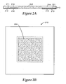
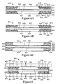
- FIGS 2A and 2B illustrate cross sectional and plan views, respectively, of a GIG in accordance with one embodiment.
- the GIG includes a gasket 210 and a gas diffusion layer (GDL) 205.
- the GDL 205 can be made of any material capable of collecting electrical current from the electrode while allowing reactant gasses to pass through, typically a woven or non-woven carbon fiber paper or cloth.
- the gasket 210 is a layered structure including a first gasket layer 211 positioned relative to the GDL 205.
- the GDL 205 is slightly smaller than an aperture in the first gasket layer 211.
- the GDL 205 is positioned within the aperture of the first gasket layer 211.
- the first gasket layer 211 may comprise various types of polymer material, such as polyimide, polyethylene naphthalate (PEN), polyethylene telephthalate (PET) and/or other materials such as rigid polymeric materials that are sufficiently thin, sufficiently strong, and sufficiently compatible with the fuel cell environment, i.e., temperatures of 80-100C with exposure to water, hydrogen, or oxygen, and that provide a surface facilitating adherence to the adhesive layer as well as the second gasket layer 214.
- polymer material such as polyimide, polyethylene naphthalate (PEN), polyethylene telephthalate (PET) and/or other materials such as rigid polymeric materials that are sufficiently thin, sufficiently strong, and sufficiently compatible with the fuel cell environment, i.e., temperatures of 80-100C with exposure to water, hydrogen, or oxygen, and that provide a surface facilitating adherence to the adhesive layer as well as the second gasket layer 214.
- the gasket 210 includes an adhesive layer 212 and an optional adhesive liner 213 disposed on one surface of the first gasket layer 211.
- the adhesive layer 212 may comprise a pressure sensitive adhesive (PSA) or a heat activated adhesive.
- PSA pressure sensitive adhesive
- the adhesive layer 212 may comprise any of the following: acrylic PSA's, rubber based adhesives, ethylene maleic anhydride copolymers, olefin adhesives such as copolymers of 1-octene with ethylene or propylene, nitrile based adhesives, epoxy based adhesives, and urethane based adhesives.
- the adhesive layer 212 may comprise a thermally activated adhesive, such as Thermobond 845 (polyethylene maleate based) or Thermobond 583 (nitrile rubber based).
- the gasket 210 includes a second gasket layer 214 in contact with the first gasket layer 211 and the GDL 205.
- the second gasket layer 214 may be substantially flat as shown in Figure 2A , or may include surface features.
- a substantially flat gasket surface may be used to facilitate sealing against a fuel cell stack separator plate or flow field plate that has appropriate ridges for making the seal. In this configuration, the flat gasket deforms against the separator or flow field plate to make the seal.
- a gasket surface having microstructured features, described below, may be useful to provide enhanced sealing against a substantially flat flow field plate, for example.
- the material forming the second gasket layer 214 bonds the first gasket layer 211 to the GDL 205.
- the material forming the second gasket layer 214 comprises a silicone material.
- the second gasket layer 214 may be formed of rubber, fluoropolymer or other deformable, flowable and/or curable materials, for example.
- the second gasket layer comprises a material, denoted herein as a heat/pressure processable material that flows or deforms under application of one or both of heat and pressure.
- the heat/pressure processable material is sufficiently flowable or deformable under heat and/or pressure to form a bond between the first gasket layer and the GDL.
- any suitable gasket material may be used for the second gasket layer, including thermoplastic materials and curable materials.
- Thermoplastic elastomers and elastomeric adhesives may also be used as gasket materials.
- the elastomeric gasket is typically not electrically conductive.
- the gasket material may be selected from rubbers such as ethylene propylene diene monomer rubber (EPDM rubber) or butyl rubber, or silicones.
- Curable materials are substantially fixed when they are substantially cured. Substantially cured typically means cured to a degree such that the gasket material will maintain a stable shape in the absence of an external force. Additional further curing steps may follow.
- Thermoplastic materials are substantially fixed when they are cooled below their T g .
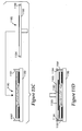
- FIG. 2C illustrates a configuration for the GIG in accordance with another embodiment.
- the GIG includes a gasket 220 bonded to a GDL 205.
- one surface of the second gasket layer 215 includes microstructured features 216.
- the microstructured features 216 enhance the sealing properties of the GIG.
- the microstructured features 216 illustrated in Figures 2C-2D are illustrated as triangular peaks and valleys, but in other embodiments the microstructured features may take on any of a variety of other shapes.
- the microstructured features may comprise closely packed hexagons.
- the microstructured features may be present on one or both of the first gasket layer and the second gasket layer.
- the height of the microstructured features may be chosen to fit a flow field plate where the sealing surface of the gasket is co-planar with the top of the flow field.
- the sealing surface of the gasket may be recessed some amount from the top of the flow field. The recessed implementation allows the microstructured features to be taller, allowing for an enhanced seal tolerance in the presence of inhomogeneities in plate thickness.
- the material of the second gasket layer 215 is in contact with, and forms a bond between, the first gasket layer 211 and the GDL 205.
- the second gasket layer 215 is disposed on a surface 219 of the first gasket layer 211 opposite the adhesive layer 212 and is adjacent the GDL 205 at an edge region 201 of the GDL.
- the material of the second gasket layer 215 contacts an edge 201 of the GDL 205 and the gasket material penetrates the GDL edge 201 to a certain depth 204, to facilitate bonding the second gasket 215 layer to the GDL 205.
- Figure 2D illustrates a GIG in accordance with another embodiment.
- the second gasket layer 217 of the GIG includes microstructured surface features 216.
- the material of the second gasket layer 217 contacts the edge 201 of the GDL and also contacts a portion of the surface 202 of the GDL 205 near the edge 201.
- the material of the second gasket layer 217 penetrates the surface 202 and/or edge 201 of the GDL 205 to a certain depth 204. The depth of penetration should be sufficient to hold the GDL and gasket together for the intended purpose of handling and MEA assembly, but not so large as to decrease the active area of the MEA significantly.
- the depth of penetration may comprise a range of about 0.1 to about 5 mm, a range of about 0.5 mm to about 3 mm, a range of about 0.5 mm to about 2 mm, or a range of about 0.5 mm to about 1 mm.
- FIG. 3A illustrates an expanded view of the single fuel cell assembly.
- Figure 3B provides a cross sectional view of the single fuel cell assembly after compression.
- the fuel cell stack comprises a five layer MEA 350, incorporating two GIGs 351, as described above, between fluid flow plates 360, 361.
- the MEA 350 includes an electrolyte membrane 352 between anode 353 and cathode 359 catalyst layers.
- one or both of the anode 353 and cathode 354 catalyst layers may be disposed on the surfaces of the electrolyte membrane 352 forming a catalyst coated membrane (CCM) 355.
- the catalyst layers 353, 359 may be disposed on the surface of the GDLs 305.
- the catalyst layers 353, 359 may be disposed partially on the electrolyte membrane 352 and partially on the GDLs 305.
- Each GIG 351 includes a GDL 305, a first gasket layer 311, adhesive layer 312 and second gasket layer 315 that bonds the first gasket layer 311 to the GDL 305.
- the GIGs 351 Prior to assembly of the gasketed MEA 350, the GIGs 351 may include an adhesive liner that is removed during assembly of the MEA 350.
- the adhesive layers 312 of the GIGs 351 adhere to the surfaces of the CCM 355 and to each other to form the gasketed MEA 350.
- the second gasket layer 315 of each GIG 351 includes optional microstructured features 316 to facilitate sealing between the GIGs 351 and the fuel flow plates 360, 361.
- Each of the flow field plates 360, 361 includes a field of gas flow channels 343 and ports through which hydrogen and oxygen fuels pass.
- flow field plates 360, 361 are configured as monopolar flow field plates.
- the flow field plates 360, 361 may comprise bipolar fluid flow plates to facilitate stacking multiple MEAs to achieve a desired voltage across the fuel cell stack.
- the surface of the second gasket layer 318 is substantially flat. The second gasket layers 318 are compressed between fuel flow plates 362, 363 having ridges 345.
- Figure 3D illustrates a single cell assembly similar to the assembly of Figure 3B , except the MEA 375 includes an electrolyte membrane 372 without catalyst layers rather than a CCM.
- the GIGs 376 include GDLs 370 having catalyst layers 373, 379 disposed thereon.
- Figure 3E illustrates a fuel cell stack incorporating multiple cells 380.
- FIGS 4A and 4B provide cross sectional and plan views, respectively, of a GIG 400 in accordance with one embodiment.
- the GIG 400 includes a gasket 410 and gas diffusion layer (GDL) 405.
- GDL gas diffusion layer
- the gasket 410 is a layered structure including a first gasket layer 411 positioned relative to the GDL 405.
- the GDL 405 is slightly smaller than an aperture 490 in the first gasket layer 411.
- the GDL 405 is positioned within the aperture 490 of the first gasket layer 411.
- the first gasket layer 411 may comprise various types of polymer material, such as polyimide, polyethylene naphthalate (PEN), polyethylene telephthalate (PET) and/or other similar materials, including rigid polymeric materials that are sufficiently thin, sufficiently strong, and sufficiently compatible with the fuel cell environment, i.e., temperatures of 80-100C, in the presence of water, hydrogen and/or oxygen.
- the gasket 410 includes an adhesive layer 412 disposed on one surface of the first gasket layer 411 and optionally includes an adhesive liner 413.
- the material of the first gasket layer 411 and the adhesive layer 412 are selected so that the adhesive layer 412 adheres well to the first gasket layer 411.
- the adhesive layer 412 may comprise a pressure sensitive adhesive (PSA) or heat activated adhesive.
- the gasket 410 includes a second gasket layer 414 that bonds together the GDL 405 and the first gasket layer 411.
- the second gasket layer 414 may be formed from a material that is solid at room temperature and is processed by heat and/or pressure to form the bond between the GDL 405 and the first gasket layer 411. Application of heat and/or pressure to the material causes the material to flow or to deform sufficiently to form the bond between the GDL 405 and the first gasket layer 411.
- the material used to form the second gasket layer 414 is referred to herein as a heat/pressure processable material.
- Suitable materials for formation of the second gasket layer include, for example, heat processable polymers or thermoplastic sealing materials.
- the thermoplastic materials can be a fluoroplastic like THV (terpolymer of tetrafluoroethylene, hexafluoropropylene and vinylidene difluoride), polyethylene, copolymers of polyethylene such as those of ethylene and acrylic acid, Thermo-Bond 845 (manufactured by 3M, e.g., a polyethylene maleic anhydride copolymer) and Thermo-Bond 668 (manufactured by 3M, e.g., a polyester). Blends of these materials or composite materials of these with fillers such as carbon, glass, ceramic, etc. may also be used as thermoplastics.
- the melt range may be 50-180° C, for example, or 100-150°C.
- a surface of the first gasket layer 411 and/or the second gasket layer 414 may include surface features such as microstructured features 416.
- the microstructured features 416 enhance the sealing properties of the GIG.
- the microstructured features 416 may be formed in a variety of shapes including closely packed hexagons, or any other shape.
- the height of the microstructured features 416 can be chosen to fit a separator flow field plate where the sealing surface of the GIG is co-planar with the top of the flow field, or where the sealing surface is recessed some amount. The recessed version allows the microstructured features 416 to be taller, allowing for increased seal tolerance in the presence of inhomogeneities in plate thickness.
- the preferred surface feature 416 of the first and/or second gasket layers 411, 414 is substantially flat to facilitate bonding to a fuel cell flow field plate that has appropriate ridges for making the seal.
- a heat/pressure processable material that is used to form the second gasket layer 414 is cut into a frame having an aperture and is placed over an outer edge 406 ( Figure 4B ) of the GDL 405 and an inner edge 417 of the first layer gasket 411.
- heat and/or pressure are applied to the subassembly, causing some of the heat/pressure processable material to flow into the adjacent edge and/or surface of the GDL 405 and into the adjacent edge and/or surface of the first gasket layer 411.
- Application of heat and/or pressure causes the second gasket layer 414 to adhere to both the first gasket layer 411 and the GDL 405, thus attaching the first gasket layer 411 to the GDL 405.
- the surface of the compression tool used for the hot press may have the microstructure features on it (in negative) to develop microstructured features on the surface of the first and/or second gasket layers 411, 414.
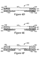
- the GDL 405 of a GIG 401 may additionally include a catalyst layer 415 disposed on one surface, as illustrated in Figure 4C .
- Figures 4D and 4E illustrate embodiments of GIGs 402, 403 where the first gasket layer 421, having an adhesive layer 422 and optional adhesive liner 423, is positioned under the GDL 425.
- the second gasket layer 424,427 is disposed on the first gasket layer 421 adjacent the GDL 425.
- material of the second gasket layer 424,427 may overlap the top surface of the GDL 425.
- the second gasket layer 424,427 may include microstructured features 426 ( Figure 4D ) or have a substantially flat sealing surface 428 ( Figure 4E ).
- the GIG is assembled by placing or depositing the heat/pressure processable gasket material used to form the second gasket layer on the first gasket layer prior to arrangement of the GDLs on the first gasket layer.
- the heat/pressure processable gasket material may be screen printed or otherwise deposited on the surface of the first gasket layer.
- the GDL is then positioned over the first gasket layer.
- a portion of the gasket material of the second gasket layer may be disposed between the GDL and the first gasket layer.
- heat and/or pressure are applied to the subassembly, causing some of the heat/pressure processable material to flow into an adjacent edge and/or surface of the GDL and into an adjacent edge and/or surface of the first gasket layer.
- Figure 4F illustrates a GIG 404 that may be formed according the above-described process.
- some of the heat/pressure processable material 485 of the second gasket layer is disposed between the GDL 480 and the first gasket layer 481.
- the first gasket layer 481 includes an adhesive layer 482 and optional adhesive liner 483.
- the second gasket layer 484 may include microstructured features, or may be substantially flat, as illustrated in Figure 4F .
- a web comprising a plurality of GIGs may be fabricated as a GIG subassembly web in a roll-to-roll process.
- Figure 5A illustrates a cross sectional view of GIG web 500 comprising a plurality of GIGs 510 similar to the GIGs illustrated in Figures 4A - 4C .
- the heat/pressure processable material that forms the second gasket layer 514 may be disposed on a first carrier web 531 and the first gasket layer may be disposed on a second carrier web 532 during the fabrication process.
- the heat/pressure processable material that forms the second gasket layer 514 is brought together with the first gasket material 511 and GDLs 505 at a compression device, such as a pair of bonding rollers, through movement of the first and second carrier webs 531, 532.
- a compression device such as a pair of bonding rollers
- heat and/or pressure are applied to the heat/pressure processable material causing the material to flow or deform, forming the second gasket layer 514 which bonds the first gasket material 511 to the GDLs 505.
- Each GIG may or may not include microstructured features 516.
- An adhesive layer 512 and optional adhesive liner 513 are disposed on the first gasket layer 511.
- Figure 5B illustrates in plan view (not to scale) of a GIG subassembly web including the second carrier web 532 and absent the first carrier web 531 illustrated in Figure 5A .
- FIG. 5C illustrates a cross sectional view of GIG web 502 comprising a plurality of GIGs 520 in accordance with one embodiment.
- the heat/pressure processable material that forms the second gasket layer 524 may be disposed on a first carrier web 531 and the first gasket layer may be disposed on a second carrier web 532 during the fabrication process prior to bonding.
- the heat/pressure processable material that forms the second gasket layer 524 is brought together with the first gasket material 521 and GDLs 525 at a compression device, such as a pair of bonding rollers, through movement of the first and second carrier webs 531, 532.
- a compression device such as a pair of bonding rollers
- heat and/or pressure are applied to the heat/pressure processable material causing the material to flow or deform, forming the second gasket layer 524 which bonds the first gasket material 521 to the GDLs 525.
- An adhesive layer 522 and optional adhesive liner 523 are disposed on the first gasket layer 521.
- GIGs and/or GIG subassembly webs fabricated according to the processes described above and depicted in Figures 4A-5C may be used in subsequent processes to form MEAs or MEA subassembly webs.
- Figures 6A and 6B illustrate MEAs fabricated using GIGs disposed on first and second surfaces of a catalyst coated electrolyte membrane.
- Figure 6A illustrates GIGs 610, 620 disposed on first and second surfaces of a catalyst coated electrolyte membrane (CCM) 630.
- Each GIG 610, 620 includes a first gasket layer 611, 621 that may include microstructured features 616, 626.
- An adhesive layer 612, 622 is disposed on each of the first gasket layers 611, 621.
- Each of the first gasket layers 611, 621 of GIGs 610, 620 have apertures with GDLs 605, 606 arranged within the apertures.
- the GDLs 605, 606 illustrated in Figure 6A are slightly smaller than the apertures of the first gasket layers 611, 621 so that the GDLs 605, 606 fit within the apertures of first gasket layers 611, 621.
- the GDLs 605, 606 may be slightly larger than the apertures of the first gasket layers 611, 621 so that outer edges 617, 627 of the GDLs 605, 606 overlap the inner edges 618, 628 of the first gasket layers 611, 621.
- Each GIG includes a second gasket layer 614, 624 formed from a heat/pressure processable material.
- the heat/pressure processable material flows to form the second gasket layer 614, 624 that bonds the first gasket layer 611, 621 and the GDL 605, 606.
- microstructured features may be imparted to the second gasket layer 614 and/or the first gasket layer 611 to enhance the sealing properties of the GIG 601.
- Figure 6B illustrates an MEA 601 similar to the MEA illustrated in Figure 6A , except that the GIGS 650, 660 of Figure 6B include catalyst layers 633, 634 on the surfaces of the GDLs 607, 608.
- the electrolyte membrane 636 may or may not include catalyst layers.
- FIG. 6C illustrates GIGs 680, 690 disposed on first and second surfaces of a catalyst coated electrolyte membrane (CCM) 630 having a membrane 635 and catalyst layers 631, 632.
- Each GIG 680, 690 includes a first gasket layer 641, 651.
- An adhesive layer 642, 652 is disposed on each of the first gasket layers 641, 651.
- the GDLs 603, 609 overlap the first gasket layers 641, 651.
- Each GIG 680, 690 includes a second gasket layer 644, 654 formed from a heat/pressure processable material.
- the second gasket layers 644, 654 include microstructured features 626, 656.
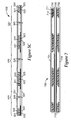
- FIG 7 illustrates a cross sectional view of an MEA subassembly web 700 comprising a plurality of MEAs which may be fabricated by a roll-to-roll manufacturing process in accordance with one embodiment.
- the MEA subassembly web 700 may be fabricated using two GIG subassembly webs as illustrated in Figure 5A , following removal of the second carrier web from each GIG subassembly. Following removal of the second carrier web and the adhesive liner, if used, one of the GIG subassemblies 701 is adhesively bonded to one surface of the CCM 730 via the adhesive layer 712 of the first gasket layer 711.
- Another of the GIG subassemblies 702 is adhesively bonded to the opposite surface of the CCM 730 to form the MEA subassembly web 700.
- the process leaves the first carrier webs 731 of each of the GIG subassemblies webs 701, 702 intact which may facilitate handling of the MEA subassembly web 700 in subsequent processing steps.
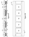
- FIG. 8 there is illustrated a cross sectional view of a single cell assembly of a fuel cell stack 800 in accordance with an embodiment of the invention.
- the fuel cell stack comprises a five layer MEA 850, incorporating two GIGs 851, 855 as described above, sandwiched between fluid flow plates 860, 861.
- Fabrication of fuel cells including MEAs and flow field plates may be accomplished by a roll to roll process.
- Methods and devices useful in roll to roll fuel cell fabrication, including flow field separator plates suitable for roll to roll processing, are described in commonly owned U.S. Patent Publication No. 20060141328 which is incorporated herein by reference in its entirety.
- the MEA 850 of the fuel cell 800 includes an electrolyte membrane 852 between anode 853 and cathode 854 catalyst layers.
- one or both of the anode 853 and cathode 854 catalyst layers may be disposed on the surfaces of the electrolyte membrane 852 forming a catalyst coated membrane (CCM).
- CCM catalyst coated membrane
- the catalyst layers 853, 854 may be disposed on the surface of the GDLs 805, 825.
- the catalyst layers 853, 854 may be disposed partially on the electrolyte membrane 852 and partially on the GDLs 805, 825.
- the anode and cathode catalyst layers 853, 854 are disposed between the electrolyte membrane 852 and GIGs 851, 855 configured as described herein.
- Each GIG 851, 855 includes a GDL 805, 825 a first gasket layer 811, 821 adhesive layer 812, 822 and second gasket layer 814, 824 that bonds the first gasket layer 811, 821 to the GDL 805, 825.
- the GIGs 851, 855 Prior to assembly of the gasketed MEA 850 the GIGs 851, 855 optionally include an adhesive liner that is removed during assembly of the MEA 850. After removal of the adhesive liner, the adhesive layers 812, 822 of the GIGs 851, 855 adhere to the surfaces of the CCM and/or in some configurations to each other to form the gasketed MEA 850.
- the first gasket layer 811, 821 and/or the second gasket layer 814, 824 of the GIGs 851, 855 include optional microstructured features 816, 826 to facilitate sealing between the GIG 851, 855 and the fuel flow plates 860, 861.
- Each of the flow field plates 860, 861 includes a field of gas flow channels 843 and ports through which hydrogen and oxygen fuels pass.
- flow field plates 860, 861 are configured as monopolar flow field plates. In other configurations, the flow field plates 860, 861 may comprise bipolar fluid flow plates to facilitate stacking multiple MEAs to achieve a desired voltage across the fuel cell stack.
- Any suitable electrolyte membrane may be used in the practice of the present invention.
- Useful PEM thicknesses range between about 200 ⁇ m and about 15 ⁇ m.
- NAFION ® is commonly used in making polymer electrolyte membranes for use in fuel cells.
- TFE tetrafluoroethylene
- the catalyst layers may comprise Pt or Pt alloys coated onto larger carbon particles by wet chemical methods, such as reduction of chloroplatine acid.
- This form of catalyst is dispersed with ionomeric binders, solvents, and often polytetrafluoroethylene (PTFE) particles to form an ink, paste, or dispersion that is applied either to the membrane or the GDLs.
- PTFE polytetrafluoroethylene
- the catalyst layers may comprise nanostructured support elements bearing particles or nanostructured thin films (NSTF) of catalytic material.
- Nanostructured catalyst layers do not contain carbon particles as supports and therefore may be incorporated into very thin surface layers of the electrolyte membrane forming a dense distribution of catalyst particles.
- the use of NSTF catalyst layers allows much higher catalyst utilization than catalyst layers formed by dispersion methods, and offer more resistance to corrosion at high potentials and temperatures due to the absence of carbon supports.
- the catalyst surface area of a CCM may be further enhanced by embossing microstructured features onto an electrolyte membrane.
- the NSTF catalyst is coated onto a microstructured catalyst transfer substrate which upon lamination transfer of catalyst to the electrolyte membrane under heat and pressure causes the electrolyte membrane's surface to be micro-replicated.
- Methods and systems directed to microstructured catalyst transfer substrates are described in commonly owned U.S. Patent 6,136,412 which is incorporated herein by reference.
- Various methods for making microstructured electrolyte membranes and NSTF catalyst layers are described in the following commonly owned patent documents which are incorporated herein by reference: U.S. Patents 4,812,352 and 5,879,827 , and U.S. Patent Application S/N 11/225,690 filed on Sept. 13, 2005 and U.S. Patent Application S/N. 11/224,879 filed on Sept. 13, 2005 .
- NSTF catalyst layers comprise elongated nanoscopic particles that may be formed by vacuum deposition of catalyst materials on to acicular nanostructured supports.
- Nanostructured supports suitable for use in the present invention may comprise whiskers of organic pigment, such as C.I. PIGMENT RED 149 (perylene red).
- the crystalline whiskers have substantially uniform but not identical cross-sections, and high length-to-width ratios.
- the nanostructured support whiskers are coated with coating materials suitable for catalysis, and which endow the whiskers with a fine nanoscopic surface structure capable of acting as multiple catalytic sites.
- the nanostructured support elements may be extended through continued screw dislocation growth. Lengthening and/or increasing the density of the nanostructured support elements allows for an increased surface area for catalysis. Processes for lengthening the nanostructured support elements are described in previously incorporated U.S. Patent Application No. 11/225,690 . Additionally, or alternatively, multiple layers of nanostructured support elements also provide for an increased surface area. Processes for producing multiple layers of nanostructured support elements are described in previously incorporated U.S. Patent Application No. 11/224,879 .
- the nanostructured support elements are coated with a catalyst material to form a nanostructured thin film catalyst layer. According to one implementation, the catalyst material comprises a metal, such as a platinum group metal.
- the catalyst coated nanostructured support elements may be transferred to a surface of an electrolyte membrane to form a catalyst coated membrane. In another embodiment, the catalyst coated nanostructured support elements may be formed on a GDL surface.
- the GDLs can be any material capable of collecting electrical current from the electrode while allowing reactant gasses to pass through, typically a woven or non-woven carbon fiber paper or cloth.
- the GDLs provide porous access of gaseous reactants and water vapor to the catalyst and membrane, and also collect the electronic current generated in the catalyst layer for powering the external load.
- GDLs may be any suitable electrically conductive porous substrate, such as carbon fiber constructions (e.g., woven and non-woven carbon fiber constructions).
- carbon fiber constructions e.g., woven and non-woven carbon fiber constructions.
- Examples of commercially available carbon fiber constructions include trade designated “AvCarb P50” carbon fiber paper from Ballard Material Products, Lowell, MA; “Toray” carbon paper which may be obtained from ElectroChem, Inc., Woburn, MA; "SpectraCarb” carbon paper from Spectracorp, Lawrence, MA; “AFN” non-woven carbon cloth from Hollingsworth & Vose Company, East Walpole, MA; and “Zoltek” carbon cloth from Zoltek Companies, Inc., St. Louis, MO, and "U-105" carbon cloth from Mitsubishi Rayon Co., Tokyo, Japan.
- GDLs may also be treated to increase or impart hydrophobic properties.
- GDLs may be treated with highly-fluorinated polymers, such as polytetrafluoroethylene (
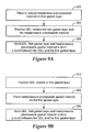
- FIG. 9A illustrates a process for making a GIG in accordance with an embodiment of the invention.
- the process may be implemented for individual GIGs or for multiple GIGs formed as a roll good.
- a heat and/or pressure processable material is placed or deposited 902 on a first gasket layer which includes an adhesive layer and an optional adhesive liner.
- the heat/pressure processable material may be silk screen printed or deposited by other methods on the surface of the first gasket layer before or after one or more apertures are cut into the first gasket layer.
- the deposition of the heat/pressure processable material may be performed so that the heat/pressure processable material has a thickness gradient across the surface of the first gasket layer.
- GDLs are positioned 904 relative to the first gasket layer so that they overlap the edges of the first gasket layer apertures and some of the heat/pressure processable material is disposed between the first gasket layer and the GDL.
- the thickness of the heat/pressure processable material under the GDL may have a thickness that is less than the thickness of the heat/processable material elsewhere on the first gasket layer, for example.
- the subassembly including the GDL, the first gasket layer and the heat/pressure processable material is molded 906 at a bonding station. The heat/pressure processable material deforms or flows to form a second gasket layer that bonds the first gasket layer to the GDL.
- FIG. 9B is a diagram illustrating a process for making a GIG in accordance with another embodiment.
- a GDL is positioned 910 relative to an edge of a first gasket layer.
- the GDL may be positioned relative to an inner edge of the first gasket layer, the inner edge framing an aperture in the first gasket layer.
- the first gasket layer includes an adhesive layer on one surface and, optionally, an adhesive liner.
- a gasket material that flows or deforms due to heat and/or pressure is placed 920 on the surface of the first gasket layer opposite the adhesive layer and/or on the mold plate.
- the GDL, first gasket layer, and gasket material are placed in a mold and molded 930.
- the molding process forms a second gasket layer from the gasket material and bonds the GDL and the first gasket layer.
- the gasket material comprises a heat/pressure processable polymer die cut to lay over the adjoining edges of the GDL and first gasket layer.
- microstructured features are embossed on the surface of the second gasket layer and/or the first gasket layer during the molding process.
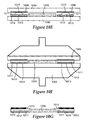
- a first gasket layer 1011 is die cut to have an aperture 1060 slightly larger than the size of a GDL.
- the first gasket layer 1011 may comprise PEN, PET, polyimide, or other suitable polymer.
- the first gasket layer 1011 has an adhesive layer 1012 and an optional adhesive liner 1013.
- the first gasket layer may have a thickness of about 0.125 mm
- the adhesive layer may have a thickness of less than about 0.0125 mm
- the adhesive liner may have a thickness of about 0.025 mm.
- the die-cut first gasket layer/adhesive/liner 1011-1013 is placed, adhesive liner 1013 side down, onto a flat plate 1090 having a release coating or liner to which the GDL and the material of the second gasket layer, e.g., silicone, do not adhere ( Figure 10B ).
- a GDL 1005 is installed into the aperture of the first gasket layer, as depicted in Figure 10C .
- a bead 1018 of flowable, curable gasket material, such as silicone is placed on the free surface of the first gasket layer 1011 ( Figure 10D ).
- a mold plate 1095 is installed on top of the above subassembly ( Figure 10E ).
- the mold plate 1095 has a release coating that prevents the material of the flowable gasket material from adhering.
- the mold plate 1095 may incorporate a microstructured patterned surface 1096 corresponding to the area of the first gasket layer 1011.
- the mold plate 1095 may have a recess of a specific depth, e.g., about 0 to about 0.250 mm, to accommodate some fraction of the height of the GDL 1005.
- the above subassembly is installed into a press and is molded ( Figure 10F ) under heat and pressure, for example, about 25 to about 30 tons at about 60° C to about 150° C, for about 2 to about 10 minutes, allowing the silicone to flow and the GIG to reach the desired thickness.
- the silicone is allowed to cure, forming the second gasket layer 1015.
- Figure 10G illustrates the GIG after removal from the press 1060. The steps described may be performed in any suitable order.
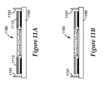
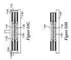
- Figures 11A-11H show a number of diagrams illustrating a process for making an MEA incorporating a GIG in accordance with embodiments of the present invention.
- Figure 11A illustrates a first GIG 1180 that has been placed on a vacuum table 1190 having alignment pins 1191 configured to facilitate positioning of the various layers of the multilayer MEA.
- the microporous layer of the first GIG 1180 faces upwards. Vacuum is applied to hold the first GIG 1180 in place.
- the adhesive liner 1113 is removed from the first GIG 1180, as illustrated in Figure 11B .
- Figure 11C illustrates a CCM 1185 that has been placed onto a vacuum plate 1193, which has appropriate alignment features 1194 to engage with pins 1191 of the vacuum table 1190.
- Vacuum is applied to the vacuum plate 1193, holding the CCM 1185 in place.
- the vacuum plate 1193 holding the CCM 1185 is placed on top of the vacuum table 1190/first GIG 1180, aligning the pins 1191 and features 1194 to provide accurate mating of the first GIG 1180 and CCM 1185 layers, as illustrated in Figure 11D .
- the vacuum is removed from the vacuum plate 1193 and the vacuum plate 1193 is removed, leaving the CCM 1185 adhesively attached to the first GIG 1180.
- a second GIG 1181 is placed in the vacuum plate 1193, microporous layer side up, as depicted in Figure 11E . Vacuum is applied to hold the second GIG 1181 in place. The adhesive liner 1114 is removed from the second GIG 1181. The vacuum plate 1193/second GIG 1181 is placed on top of the CCM 1185/first GIG 1180 assembly on the vacuum table 1190, illustrated in Figure 11G . The vacuum is removed from the vacuum plate 1193 and the plate 1193 is removed leaving the second GIG 1181/CCM 1185/first GIG 1180 MEA assembly, as illustrated in Figure 11H . The MEA is removed from the vacuum table 1190 and may be die cut to set the outer dimensions of the part.
- GIGs configured in accordance with embodiments described herein may be fabricated via continuous and/or roll-to-roll processes described in commonly owned U.S. Patent Application identified by Attorney Docket No. 62591US002 filed concurrently with the present application and incorporated herein by reference.
- the GIGs configured in accordance with the embodiments presented herein provides numerous advantages over prior gasketing approaches.
- Prior processes require the MEA and GDLs to be exposed to higher than desirable temperatures and pressures required for gasket formation or for bonding fuel cell components (e.g., bonding a GDL to a CCM, or bonding a catalyst coated GDL to an electrolyte membrane). Exposure to high temperatures and pressures during the manufacturing process may lead to electronic shorting of the GDLs through the CCM.
- the GIGs as described herein may be manufactured using temperatures in excess of those tolerable by the CCM. The use of GIGs of the present invention spares the CCM from exposure to these excessive temperatures, thus allowing for potentially faster cycle times in the slow gasket making procedure. The speed of the curing procedure depends upon the specific material used. In addition, curing of gasket materials, such as silicone, may release species that are detrimental to the CCM. Use of the GIGs as described herein does not expose the CCM to the gasket curing process.
- GIGs as described herein may be used to minimize scrapping the CCM during the manufacturing process. Forming the GIGs first and then attaching them to the CCM means that any failures in the gasket making process does not lead to waste of the more expensive CCM.
- gasketing approaches require that the gasket layer, e.g., PEN, PET, or other polymer, bonds well to the CCM. Insufficient bonding results in leaks that occur when the MEA is placed under operating conditions. Insufficient bonding also leads to difficulty in handling subassemblies during manufacture and stack assembly processes if the gasket fails to adhere and falls off the electrolyte membrane.
- the gasketing approaches described herein provide enhanced bonding at the GIG/CCM interface and are particularly advantageous when nanostructured thin film catalyst layers are used.
- FIGS 12-15 illustrate various fuel cell systems that may incorporate the fuel cell assemblies described herein and use a fuel cell stack for power generation.
- the fuel cell system 1200 shown in Figure 12 depicts one of many possible systems in which a fuel cell assembly as illustrated by the embodiments herein may be utilized.
- the fuel cell system 1200 includes a fuel processor 1204, a power section 1206, and a power conditioner 1208.
- the hydrogen rich fuel 1202 is supplied to the power section 1206.
- the hydrogen rich fuel 1202 is introduced into the stack of MEAs of the fuel cell stack(s) contained in the power section 1206.
- a supply of air 1203 is also provided to the power section 1206, which provides a source of oxygen for the stack(s) of fuel cells.
- the fuel cell stack(s) of the power section 1206 produce DC power 1210, heat 1212, and clean water 1213.
- Polymer electrolyte membrane fuel cell systems may resupply product water 1213 to the fuel processor 1204, which makes a large fraction of its hydrogen from water and the rest from the methane or other fuel 1201.
- the DC power 1210 produced by the power section 1206 is transmitted to the power conditioner 1208, which converts DC power 1210 to AC power 1211 for subsequent use. It is understood that AC power conversion need not be included in a system that provides DC output power.
- Figure 13 illustrates a fuel cell power supply 1300 including a fuel supply unit 1305, a fuel cell power section 1306, and a power conditioner 1308.
- the fuel supply unit 1305 includes a reservoir containing hydrogen fuel that is supplied to the fuel cell power section 1306.
- the hydrogen fuel is introduced along with air or oxygen into the MEAs of the fuel cell stack(s) contained in the power section 1306.
- the power section 1306 of the fuel cell power supply system 1300 produces DC power, useable heat, and clean water.
- the DC power produced by the power section 1306 may be transferred to the power conditioner 1308, for conversion to AC power, if desired.
- the fuel cell power supply system 1300 illustrated in Figure 13 may be implemented as a stationary or portable AC or DC power generator, for example.
- a fuel cell system 1400 uses power generated by a fuel cell power supply to provide power to operate a computer.
- fuel cell power supply system includes a fuel supply unit 1405 and a fuel cell power section 1406.
- the fuel supply unit 1405 provides hydrogen fuel to the fuel cell power section 1406.
- the fuel cell stack(s) of the power section 1406 produce power that is used to operate a computer 1410, such as a desk top or laptop computer.
- a fuel cell system 1500 uses power from a fuel cell power supply to operate an automobile.
- a fuel supply unit 1505 supplies hydrogen fuel to a fuel cell power section 1506.
- the fuel cell stack(s) of the power section 1506 produce power used to operate a motor 1508 coupled to a drive mechanism of the automobile 1510.
Claims (15)
- Sous-ensemble pour un ensemble d'électrode à membrane de pile à combustible (MEA), le sous-ensemble comprenant:- une couche de diffusion de gaz (CDG); et- une garniture liée à la CDG, la garniture comprenant:dans lequel la matière de garniture de la deuxième couche de garniture pénètre dans la CDG.- une première couche de garniture;- une deuxième couche de garniture comprenant une matière de garniture en contact avec la première couche de garniture et la CDG, la matière de garniture liant la CDG à la première couche de garniture; et- une couche d'adhésif disposée sur une surface de la première couche de garniture;
- Sous-ensemble selon la revendication 1, dans lequel la deuxième couche de garniture est disposée sur une partie d'une surface de la CDG.
- Sous-ensemble selon la revendication 1, dans lequel la deuxième couche de garniture comprend des caractéristiques microstructurées sur au moins une surface.
- Sous-ensemble selon la revendication 1, dans lequel la première couche de garniture comprend un polymère.
- Sous-ensemble selon la revendication 1, dans lequel la première couche de garniture comprend du PEN, du PET ou du polyimide.
- Sous-ensemble selon la revendication 1, dans lequel la matière de garniture comprend du silicone, du caoutchouc ou du fluoropolymère.
- Sous-ensemble selon la revendication 1, dans lequel la matière de garniture comprend une matière qui est apte au fluage ou à la déformation lors d'une application de chaleur et/ou de pression.
- Sous-ensemble selon la revendication 1, dans lequel la CDG est disposée à l'intérieur d'une ouverture de la première couche de garniture.
- Sous-ensemble selon la revendication 1, dans lequel la CDG recouvre la première couche de garniture.
- Sous-ensemble selon la revendication 1, dans lequel la couche d'adhésif comprend une doublure adhésive amovible.
- Sous-ensemble selon la revendication 1, dans lequel le sous-ensemble est un composant d'un rouleau de tissu, le rouleau de tissu comprenant une pluralité de sous-ensembles similaires.
- Procédé de fabrication d'un sous-ensemble pour un ensemble d'électrode à membrane, comprenant les étapes suivantes:- préparer des composants de sous-ensemble, comprenant:- le positionnement d'une couche de diffusion de gaz (CDG) par rapport à une première couche de garniture comportant une couche d'adhésif disposée sur celle-ci; et- le dépôt d'une matière de garniture sur la première couche de garniture; et- mouler les composants du sous-ensemble pour réaliser une liaison entre la première couche de garniture et la CDG, la liaison étant formée par la pénétration de la matière de garniture dans la CDG.
- Procédé selon la revendication 12, dans lequel:- la préparation des composants du sous-ensemble comprend en outre la découpe d'une ouverture dans la première couche de garniture; et- le positionnement de la CDG par rapport à la première couche de garniture comprend le positionnement de la CDG à l'intérieur de l'ouverture.
- Procédé selon la revendication 12, comprenant en outre le durcissement de la matière de garniture.
- Procédé selon la revendication 12, dans lequel le moulage des composants du sous-ensemble comprend la formation d'une deuxième couche de garniture présentant des caractéristiques microstructurées ou gaufrées à partir de la matière de garniture.
Applications Claiming Priority (2)
| Application Number | Priority Date | Filing Date | Title |
|---|---|---|---|
| US11/611,553 US7732083B2 (en) | 2006-12-15 | 2006-12-15 | Gas diffusion layer incorporating a gasket |
| PCT/US2007/085159 WO2008073680A1 (fr) | 2006-12-15 | 2007-11-20 | Couche de diffusion de gaz incorporant un joint |
Publications (2)
| Publication Number | Publication Date |
|---|---|
| EP2095453A1 EP2095453A1 (fr) | 2009-09-02 |
| EP2095453B1 true EP2095453B1 (fr) | 2010-05-12 |
Family
ID=39125248
Family Applications (1)
| Application Number | Title | Priority Date | Filing Date |
|---|---|---|---|
| EP07854709A Active EP2095453B1 (fr) | 2006-12-15 | 2007-11-20 | Couche de diffusion de gaz incorporant un joint |
Country Status (7)
| Country | Link |
|---|---|
| US (1) | US7732083B2 (fr) |
| EP (1) | EP2095453B1 (fr) |
| JP (1) | JP5363335B2 (fr) |
| CN (1) | CN101563803B (fr) |
| AT (1) | ATE467919T1 (fr) |
| DE (1) | DE602007006549D1 (fr) |
| WO (1) | WO2008073680A1 (fr) |
Cited By (1)
| Publication number | Priority date | Publication date | Assignee | Title |
|---|---|---|---|---|
| DE102011105071A1 (de) | 2011-06-21 | 2012-12-27 | Daimler Ag | Haltevorrichtung mit einer Membran einer Membran-Elektroden-Einheit für eine Brennstoffzelle und Verfahren zu deren Herstellung |
Families Citing this family (37)
| Publication number | Priority date | Publication date | Assignee | Title |
|---|---|---|---|---|
| US8288059B2 (en) | 2006-12-15 | 2012-10-16 | 3M Innovative Properties Company | Processing methods and systems for assembling fuel cell perimeter gaskets |
| US8012284B2 (en) * | 2006-12-15 | 2011-09-06 | 3M Innovative Properties Company | Method and apparatus for fabricating roll good fuel cell subassemblies |
| JP5125102B2 (ja) * | 2007-01-05 | 2013-01-23 | トヨタ自動車株式会社 | 燃料電池、燃料電池を構成するシール一体部材、および、その製造方法 |
| US9722269B2 (en) | 2008-01-11 | 2017-08-01 | GM Global Technology Operations LLC | Reinforced electrode assembly |
| US9780399B2 (en) | 2008-01-11 | 2017-10-03 | GM Global Technology Operations LLC | Electrode assembly with integrated reinforcement layer |
| US9647274B2 (en) * | 2008-01-11 | 2017-05-09 | GM Global Technology Operations LLC | Method of making a proton exchange membrane using a gas diffusion electrode as a substrate |
| US9419286B2 (en) | 2011-01-13 | 2016-08-16 | GM Global Technology Operations LLC | Wet lamination process for reducing mud cracking in fuel cell components |
| WO2010030654A1 (fr) * | 2008-09-09 | 2010-03-18 | Bdf Ip Holdings Ltd. | Conception de joint à faible charge de compression pour pile à combustible à électrolyte polymère solide |
| US8802329B2 (en) * | 2009-05-14 | 2014-08-12 | GM Global Technology Operations LLC | Electrode containing nanostructured thin catalytic layers and method of making |
| US8481231B2 (en) | 2009-05-14 | 2013-07-09 | GM Global Technology Operations LLC | Preparation of nanostructured thin catalytic layer-based electrode ink |
| US8512908B2 (en) * | 2009-05-14 | 2013-08-20 | GM Global Technology Operations LLC | Fabrication of catalyst coated diffusion media layers containing nanostructured thin catalytic layers |
| US8507152B2 (en) * | 2009-05-14 | 2013-08-13 | GM Global Technology Operations LLC | Fabrication of electrodes with multiple nanostructured thin catalytic layers |
| US20110171562A1 (en) * | 2010-01-08 | 2011-07-14 | Gm Global Technology Operations, Inc. | Process for forming a membrane-subgasket assembly using vacuum sealing |
| US8445164B2 (en) | 2010-05-27 | 2013-05-21 | GM Global Technology Operations LLC | Electrode containing nanostructured thin catalytic layers and method of making |
| US9012346B2 (en) | 2010-11-04 | 2015-04-21 | GM Global Technology Operations LLC | Wet lamination process for reducing mud cracking in fuel cell components |
| KR101243704B1 (ko) | 2010-12-07 | 2013-03-13 | 현대자동차주식회사 | 연료전지 스택 제작 방법 |
| DE102010063254A1 (de) * | 2010-12-16 | 2012-06-21 | FuMA-Tech Gesellschaft für funktionelle Membranen und Anlagentechnologie mbH | Membran-Elektroden-Anordnung mit zwei Deckschichten |
| US8518596B1 (en) | 2012-05-16 | 2013-08-27 | GM Global Technology Operations LLC | Low cost fuel cell diffusion layer configured for optimized anode water management |
| CN104428932B (zh) * | 2012-07-10 | 2016-04-20 | 日产自动车株式会社 | 膜电极接合体 |
| JP5874830B2 (ja) | 2012-07-27 | 2016-03-02 | 日産自動車株式会社 | 燃料電池用ガスケット、燃料電池用接合体、およびシート部材の接合方法 |
| JP5907054B2 (ja) * | 2012-12-14 | 2016-04-20 | トヨタ自動車株式会社 | 燃料電池の製造方法 |
| US20160006038A1 (en) * | 2013-02-21 | 2016-01-07 | Audi Ag | Non-puncturing fuel cell gas diffusion layer |
| EP2987194B1 (fr) * | 2013-04-16 | 2019-06-12 | Basf Se | Procédé de fabrication d'assemblages membrane-électrodes |
| EP2818582B1 (fr) | 2013-06-25 | 2020-03-18 | Airbus Defence and Space GmbH | Dispositif à espace de fluide pour une unité de réaction d'un dispositif redox |
| DE102013014083A1 (de) * | 2013-08-27 | 2015-03-05 | Elcomax Gmbh | Verfahren zur Herstellung einer Membran-Elektroden-Einheit mit umlaufender Dichtung sowie Membran-Elektroden-Einheit |
| DE102015010440B4 (de) * | 2015-08-11 | 2023-10-26 | Cellcentric Gmbh & Co. Kg | Verfahren und Vorrichtung zum Herstellen einer Membran-Elektroden-Anordnung für eine Brennstoffzelle |
| GB2542803B (en) * | 2015-09-30 | 2022-01-12 | Intelligent Energy Ltd | Fuel cell sub-assembly |
| JP2019521483A (ja) * | 2016-06-15 | 2019-07-25 | スリーエム イノベイティブ プロパティズ カンパニー | 膜電極接合体構成要素及びアセンブリ製造方法 |
| DE102016225438A1 (de) * | 2016-12-19 | 2018-06-21 | Bayerische Motoren Werke Aktiengesellschaft | Verbindungselement zum elektrischen Kontaktieren von Separatorplatten eines Brennstoffzellenstapels |
| US10381658B2 (en) * | 2016-12-22 | 2019-08-13 | Plug Power Inc. | Fuel cell stack |
| AU2019299662A1 (en) * | 2018-07-05 | 2021-02-18 | Eh Group Engineering Ag | Fuel cells |
| DE102018216266A1 (de) * | 2018-09-25 | 2020-03-26 | Audi Ag | Brennstoffzellenaufbau, Brennstoffzellenvorrichtung sowie Kraftfahrzeug |
| CN109441937A (zh) * | 2018-12-14 | 2019-03-08 | 成都天府垫片科技有限公司 | 一种具有截面密封的纤维垫片及其制作方法 |
| CN111730803B (zh) * | 2020-06-30 | 2023-01-31 | 武汉理工新能源有限公司 | 密封结构的制备方法及膜电极与双极板的密封连接方法 |
| KR20220080372A (ko) * | 2020-12-07 | 2022-06-14 | 현대자동차주식회사 | 바인더의 함량이 조절된 ega 및 이를 포함하는 연료전지 스택 |
| DE102020216095A1 (de) * | 2020-12-17 | 2022-06-23 | Robert Bosch Gesellschaft mit beschränkter Haftung | Bipolarplatte, elektrochemische Zelle und Verfahren zum Herstellen einer elektrochemischen Zelle |
| CN113964362B (zh) * | 2021-12-23 | 2022-03-08 | 国家电投集团氢能科技发展有限公司 | 边框结构及具有该结构的电化学电池装置 |
Family Cites Families (30)
| Publication number | Priority date | Publication date | Assignee | Title |
|---|---|---|---|---|
| US4812352A (en) * | 1986-08-25 | 1989-03-14 | Minnesota Mining And Manufacturing Company | Article having surface layer of uniformly oriented, crystalline, organic microstructures |
| JPH10510664A (ja) | 1994-12-17 | 1998-10-13 | ラフバロウ ユニヴァーシティ イノヴェイションズ リミテッド | 電解質型燃料電池の構造 |
| US6136412A (en) * | 1997-10-10 | 2000-10-24 | 3M Innovative Properties Company | Microtextured catalyst transfer substrate |
| US5879827A (en) * | 1997-10-10 | 1999-03-09 | Minnesota Mining And Manufacturing Company | Catalyst for membrane electrode assembly and method of making |
| WO2002001658A1 (fr) * | 2000-06-29 | 2002-01-03 | Nok Corporation | Composant destine a une pile a combustible |
| JP4035055B2 (ja) * | 2001-04-23 | 2008-01-16 | Nok株式会社 | 燃料電池およびその製造方法 |
| JP4224668B2 (ja) * | 2001-06-15 | 2009-02-18 | Nok株式会社 | 燃料電池用構成部品 |
| JP4412448B2 (ja) * | 2001-06-20 | 2010-02-10 | Nok株式会社 | 燃料電池用構成部品 |
| JP5208338B2 (ja) * | 2001-06-29 | 2013-06-12 | 本田技研工業株式会社 | 電解質膜・電極構造体及び燃料電池セル |
| US6869717B2 (en) * | 2001-07-09 | 2005-03-22 | Hydrogenics Corporation | Manifold for a fuel cell system |
| US20030082430A1 (en) * | 2001-10-25 | 2003-05-01 | Daisuke Suzuki | Fuel cell gasket assembly and method of making |
| US20030221311A1 (en) * | 2002-03-20 | 2003-12-04 | Smith Jeffrey A. | Fuel cell assembly and sealing |
| US7087339B2 (en) * | 2002-05-10 | 2006-08-08 | 3M Innovative Properties Company | Fuel cell membrane electrode assembly with sealing surfaces |
| TW581327U (en) * | 2002-12-04 | 2004-03-21 | Asia Pacific Fuel Cell Tech | Integrated dual electrode plate module of fuel cell set |
| US7195690B2 (en) * | 2003-05-28 | 2007-03-27 | 3M Innovative Properties Company | Roll-good fuel cell fabrication processes, equipment, and articles produced from same |
| US20050095490A1 (en) * | 2003-10-31 | 2005-05-05 | Mittelstadt Laurie S. | Fuel cell assembly gasket for fuel containment |
| US7214442B2 (en) * | 2003-12-02 | 2007-05-08 | Los Alamos National Security, Llc | High specific power, direct methanol fuel cell stack |
| KR101147238B1 (ko) | 2004-06-29 | 2012-05-18 | 삼성에스디아이 주식회사 | 연료 전지 시스템 및 그 스택 |
| EP1624511A1 (fr) * | 2004-08-05 | 2006-02-08 | Pemeas GmbH | Assemblages membrane-électrode et piles à combustible à durée de vie prolongée |
| EP1624512A2 (fr) | 2004-08-05 | 2006-02-08 | Pemeas GmbH | Unités membrane-électrodes à longue durée |
| US7237406B2 (en) * | 2004-09-07 | 2007-07-03 | Modine Manufacturing Company | Condenser/separator and method |
| US7291415B2 (en) * | 2004-11-23 | 2007-11-06 | Versa Power Systems, Ltd. | Solid oxide fuel cell with external manifolds |
| US20060127738A1 (en) * | 2004-12-13 | 2006-06-15 | Bhaskar Sompalli | Design, method and process for unitized mea |
| US7862956B2 (en) * | 2004-12-29 | 2011-01-04 | 3M Innovative Properties Company | Z-axis electrically conducting flow field separator |
| US7544219B2 (en) | 2005-01-12 | 2009-06-09 | Lg Chem, Ltd. | Gasketed membrane-electrode-assembly and fuel cell system employing the same |
| JP4931103B2 (ja) * | 2005-01-31 | 2012-05-16 | 内山工業株式会社 | 燃料電池用構成部材 |
| JP2006236957A (ja) * | 2005-01-31 | 2006-09-07 | Uchiyama Mfg Corp | 燃料電池用構成部材 |
| JP5157050B2 (ja) * | 2005-08-02 | 2013-03-06 | 日産自動車株式会社 | 膜電極接合体及びその製造方法 |
| US20070059452A1 (en) * | 2005-09-13 | 2007-03-15 | Debe Mark K | Formation of nanostructured layers through continued screw dislocation growth |
| US20080118802A1 (en) * | 2006-11-16 | 2008-05-22 | Peter Szrama | Fully Catalyzed Membrane Assembly With Attached Border |
-
2006
- 2006-12-15 US US11/611,553 patent/US7732083B2/en not_active Expired - Fee Related
-
2007
- 2007-11-20 JP JP2009541457A patent/JP5363335B2/ja not_active Expired - Fee Related
- 2007-11-20 WO PCT/US2007/085159 patent/WO2008073680A1/fr active Application Filing
- 2007-11-20 EP EP07854709A patent/EP2095453B1/fr active Active
- 2007-11-20 DE DE602007006549T patent/DE602007006549D1/de active Active
- 2007-11-20 CN CN200780046240.3A patent/CN101563803B/zh active Active
- 2007-11-20 AT AT07854709T patent/ATE467919T1/de not_active IP Right Cessation
Cited By (1)
| Publication number | Priority date | Publication date | Assignee | Title |
|---|---|---|---|---|
| DE102011105071A1 (de) | 2011-06-21 | 2012-12-27 | Daimler Ag | Haltevorrichtung mit einer Membran einer Membran-Elektroden-Einheit für eine Brennstoffzelle und Verfahren zu deren Herstellung |
Also Published As
| Publication number | Publication date |
|---|---|
| DE602007006549D1 (de) | 2010-06-24 |
| CN101563803A (zh) | 2009-10-21 |
| WO2008073680A1 (fr) | 2008-06-19 |
| ATE467919T1 (de) | 2010-05-15 |
| US20080143061A1 (en) | 2008-06-19 |
| JP2010514100A (ja) | 2010-04-30 |
| EP2095453A1 (fr) | 2009-09-02 |
| US7732083B2 (en) | 2010-06-08 |
| CN101563803B (zh) | 2017-04-26 |
| JP5363335B2 (ja) | 2013-12-11 |
Similar Documents
| Publication | Publication Date | Title |
|---|---|---|
| EP2095453B1 (fr) | Couche de diffusion de gaz incorporant un joint | |
| EP2102930B1 (fr) | Procédé et appareil pour fabriquer des sous-ensembles de piles à combustible sous forme de bobine | |
| EP2097943B1 (fr) | Procédé de traitement pour assembler des joints de périmètre de pile à combustible | |
| US8921002B2 (en) | Manufacturing of fuel cell membrane electrode assemblies incorporating photocurable cationic crosslinkable resin gasket | |
| EP1584123B1 (fr) | Ensemble pile a combustible unitaire | |
| US7659028B2 (en) | Polymer electrolyte fuel cell | |
| EP1563562B1 (fr) | Ensemble pile a combustible unitaire et refroidisseur | |
| JP2009509300A (ja) | 燃料電池に使用されるガスケット副組立品 | |
| JP4843985B2 (ja) | 固体高分子形燃料電池用ガスケット付き電解質膜−電極接合体及びその製造方法 | |
| US20090162732A1 (en) | Fuel cell employing perimeter gasket with perceivable orientation indicator | |
| US20100075187A1 (en) | Membrane-membrane reinforcing member assembly, membrane-catalyst layer assembly, membrane-electrode assembly, and polymer electrolyte fuel cell | |
| EP2537196A2 (fr) | Joint intégré pour fabrication d'empilement de piles à combustible | |
| JP2012074315A (ja) | 固体高分子形燃料電池の膜電極接合体およびその製造方法 | |
| US20140154606A1 (en) | Fuel cell | |
| JP2014157673A (ja) | 燃料電池用電解質膜・電極構造体の製造方法 |
Legal Events
| Date | Code | Title | Description |
|---|---|---|---|
| PUAI | Public reference made under article 153(3) epc to a published international application that has entered the european phase |
Free format text: ORIGINAL CODE: 0009012 |
|
| 17P | Request for examination filed |
Effective date: 20090630 |
|
| AK | Designated contracting states |
Kind code of ref document: A1 Designated state(s): AT BE BG CH CY CZ DE DK EE ES FI FR GB GR HU IE IS IT LI LT LU LV MC MT NL PL PT RO SE SI SK TR |
|
| GRAP | Despatch of communication of intention to grant a patent |
Free format text: ORIGINAL CODE: EPIDOSNIGR1 |
|
| DAX | Request for extension of the european patent (deleted) | ||
| GRAS | Grant fee paid |
Free format text: ORIGINAL CODE: EPIDOSNIGR3 |
|
| GRAA | (expected) grant |
Free format text: ORIGINAL CODE: 0009210 |
|
| AK | Designated contracting states |
Kind code of ref document: B1 Designated state(s): AT BE BG CH CY CZ DE DK EE ES FI FR GB GR HU IE IS IT LI LT LU LV MC MT NL PL PT RO SE SI SK TR |
|
| REG | Reference to a national code |
Ref country code: GB Ref legal event code: FG4D |
|
| REG | Reference to a national code |
Ref country code: CH Ref legal event code: EP |
|
| REG | Reference to a national code |
Ref country code: IE Ref legal event code: FG4D |
|
| REF | Corresponds to: |
Ref document number: 602007006549 Country of ref document: DE Date of ref document: 20100624 Kind code of ref document: P |
|
| REG | Reference to a national code |
Ref country code: NL Ref legal event code: VDEP Effective date: 20100512 |
|
| LTIE | Lt: invalidation of european patent or patent extension |
Effective date: 20100512 |
|
| PG25 | Lapsed in a contracting state [announced via postgrant information from national office to epo] |
Ref country code: NL Free format text: LAPSE BECAUSE OF FAILURE TO SUBMIT A TRANSLATION OF THE DESCRIPTION OR TO PAY THE FEE WITHIN THE PRESCRIBED TIME-LIMIT Effective date: 20100512 Ref country code: LT Free format text: LAPSE BECAUSE OF FAILURE TO SUBMIT A TRANSLATION OF THE DESCRIPTION OR TO PAY THE FEE WITHIN THE PRESCRIBED TIME-LIMIT Effective date: 20100512 Ref country code: ES Free format text: LAPSE BECAUSE OF FAILURE TO SUBMIT A TRANSLATION OF THE DESCRIPTION OR TO PAY THE FEE WITHIN THE PRESCRIBED TIME-LIMIT Effective date: 20100823 Ref country code: SE Free format text: LAPSE BECAUSE OF FAILURE TO SUBMIT A TRANSLATION OF THE DESCRIPTION OR TO PAY THE FEE WITHIN THE PRESCRIBED TIME-LIMIT Effective date: 20100512 |
|
| PG25 | Lapsed in a contracting state [announced via postgrant information from national office to epo] |
Ref country code: FI Free format text: LAPSE BECAUSE OF FAILURE TO SUBMIT A TRANSLATION OF THE DESCRIPTION OR TO PAY THE FEE WITHIN THE PRESCRIBED TIME-LIMIT Effective date: 20100512 Ref country code: SI Free format text: LAPSE BECAUSE OF FAILURE TO SUBMIT A TRANSLATION OF THE DESCRIPTION OR TO PAY THE FEE WITHIN THE PRESCRIBED TIME-LIMIT Effective date: 20100512 Ref country code: LV Free format text: LAPSE BECAUSE OF FAILURE TO SUBMIT A TRANSLATION OF THE DESCRIPTION OR TO PAY THE FEE WITHIN THE PRESCRIBED TIME-LIMIT Effective date: 20100512 Ref country code: IS Free format text: LAPSE BECAUSE OF FAILURE TO SUBMIT A TRANSLATION OF THE DESCRIPTION OR TO PAY THE FEE WITHIN THE PRESCRIBED TIME-LIMIT Effective date: 20100912 Ref country code: AT Free format text: LAPSE BECAUSE OF FAILURE TO SUBMIT A TRANSLATION OF THE DESCRIPTION OR TO PAY THE FEE WITHIN THE PRESCRIBED TIME-LIMIT Effective date: 20100512 |
|
| PG25 | Lapsed in a contracting state [announced via postgrant information from national office to epo] |
Ref country code: CY Free format text: LAPSE BECAUSE OF FAILURE TO SUBMIT A TRANSLATION OF THE DESCRIPTION OR TO PAY THE FEE WITHIN THE PRESCRIBED TIME-LIMIT Effective date: 20100616 Ref country code: PL Free format text: LAPSE BECAUSE OF FAILURE TO SUBMIT A TRANSLATION OF THE DESCRIPTION OR TO PAY THE FEE WITHIN THE PRESCRIBED TIME-LIMIT Effective date: 20100512 |
|
| PG25 | Lapsed in a contracting state [announced via postgrant information from national office to epo] |
Ref country code: DK Free format text: LAPSE BECAUSE OF FAILURE TO SUBMIT A TRANSLATION OF THE DESCRIPTION OR TO PAY THE FEE WITHIN THE PRESCRIBED TIME-LIMIT Effective date: 20100512 Ref country code: EE Free format text: LAPSE BECAUSE OF FAILURE TO SUBMIT A TRANSLATION OF THE DESCRIPTION OR TO PAY THE FEE WITHIN THE PRESCRIBED TIME-LIMIT Effective date: 20100512 Ref country code: PT Free format text: LAPSE BECAUSE OF FAILURE TO SUBMIT A TRANSLATION OF THE DESCRIPTION OR TO PAY THE FEE WITHIN THE PRESCRIBED TIME-LIMIT Effective date: 20100913 |
|
| PG25 | Lapsed in a contracting state [announced via postgrant information from national office to epo] |
Ref country code: SK Free format text: LAPSE BECAUSE OF FAILURE TO SUBMIT A TRANSLATION OF THE DESCRIPTION OR TO PAY THE FEE WITHIN THE PRESCRIBED TIME-LIMIT Effective date: 20100512 Ref country code: BE Free format text: LAPSE BECAUSE OF FAILURE TO SUBMIT A TRANSLATION OF THE DESCRIPTION OR TO PAY THE FEE WITHIN THE PRESCRIBED TIME-LIMIT Effective date: 20100512 Ref country code: CZ Free format text: LAPSE BECAUSE OF FAILURE TO SUBMIT A TRANSLATION OF THE DESCRIPTION OR TO PAY THE FEE WITHIN THE PRESCRIBED TIME-LIMIT Effective date: 20100512 Ref country code: RO Free format text: LAPSE BECAUSE OF FAILURE TO SUBMIT A TRANSLATION OF THE DESCRIPTION OR TO PAY THE FEE WITHIN THE PRESCRIBED TIME-LIMIT Effective date: 20100512 |
|
| PLBE | No opposition filed within time limit |
Free format text: ORIGINAL CODE: 0009261 |
|
| STAA | Information on the status of an ep patent application or granted ep patent |
Free format text: STATUS: NO OPPOSITION FILED WITHIN TIME LIMIT |
|
| PG25 | Lapsed in a contracting state [announced via postgrant information from national office to epo] |
Ref country code: IT Free format text: LAPSE BECAUSE OF FAILURE TO SUBMIT A TRANSLATION OF THE DESCRIPTION OR TO PAY THE FEE WITHIN THE PRESCRIBED TIME-LIMIT Effective date: 20100512 |
|
| 26N | No opposition filed |
Effective date: 20110215 |
|
| PG25 | Lapsed in a contracting state [announced via postgrant information from national office to epo] |
Ref country code: GR Free format text: LAPSE BECAUSE OF FAILURE TO SUBMIT A TRANSLATION OF THE DESCRIPTION OR TO PAY THE FEE WITHIN THE PRESCRIBED TIME-LIMIT Effective date: 20100813 |
|
| REG | Reference to a national code |
Ref country code: DE Ref legal event code: R097 Ref document number: 602007006549 Country of ref document: DE Effective date: 20110214 |
|
| PG25 | Lapsed in a contracting state [announced via postgrant information from national office to epo] |
Ref country code: MC Free format text: LAPSE BECAUSE OF NON-PAYMENT OF DUE FEES Effective date: 20101130 |
|
| REG | Reference to a national code |
Ref country code: FR Ref legal event code: ST Effective date: 20110801 |
|
| PG25 | Lapsed in a contracting state [announced via postgrant information from national office to epo] |
Ref country code: IE Free format text: LAPSE BECAUSE OF NON-PAYMENT OF DUE FEES Effective date: 20101120 Ref country code: FR Free format text: LAPSE BECAUSE OF NON-PAYMENT OF DUE FEES Effective date: 20101130 |
|
| PG25 | Lapsed in a contracting state [announced via postgrant information from national office to epo] |
Ref country code: MT Free format text: LAPSE BECAUSE OF FAILURE TO SUBMIT A TRANSLATION OF THE DESCRIPTION OR TO PAY THE FEE WITHIN THE PRESCRIBED TIME-LIMIT Effective date: 20100512 |
|
| REG | Reference to a national code |
Ref country code: CH Ref legal event code: PL |
|
| GBPC | Gb: european patent ceased through non-payment of renewal fee |
Effective date: 20111120 |
|
| PG25 | Lapsed in a contracting state [announced via postgrant information from national office to epo] |
Ref country code: CH Free format text: LAPSE BECAUSE OF NON-PAYMENT OF DUE FEES Effective date: 20111130 Ref country code: LI Free format text: LAPSE BECAUSE OF NON-PAYMENT OF DUE FEES Effective date: 20111130 |
|
| PG25 | Lapsed in a contracting state [announced via postgrant information from national office to epo] |
Ref country code: LU Free format text: LAPSE BECAUSE OF NON-PAYMENT OF DUE FEES Effective date: 20101120 Ref country code: HU Free format text: LAPSE BECAUSE OF FAILURE TO SUBMIT A TRANSLATION OF THE DESCRIPTION OR TO PAY THE FEE WITHIN THE PRESCRIBED TIME-LIMIT Effective date: 20101113 Ref country code: BG Free format text: LAPSE BECAUSE OF FAILURE TO SUBMIT A TRANSLATION OF THE DESCRIPTION OR TO PAY THE FEE WITHIN THE PRESCRIBED TIME-LIMIT Effective date: 20100512 |
|
| PG25 | Lapsed in a contracting state [announced via postgrant information from national office to epo] |
Ref country code: GB Free format text: LAPSE BECAUSE OF NON-PAYMENT OF DUE FEES Effective date: 20111120 Ref country code: TR Free format text: LAPSE BECAUSE OF FAILURE TO SUBMIT A TRANSLATION OF THE DESCRIPTION OR TO PAY THE FEE WITHIN THE PRESCRIBED TIME-LIMIT Effective date: 20100512 |
|
| PG25 | Lapsed in a contracting state [announced via postgrant information from national office to epo] |
Ref country code: BG Free format text: LAPSE BECAUSE OF FAILURE TO SUBMIT A TRANSLATION OF THE DESCRIPTION OR TO PAY THE FEE WITHIN THE PRESCRIBED TIME-LIMIT Effective date: 20100812 |
|
| PGFP | Annual fee paid to national office [announced via postgrant information from national office to epo] |
Ref country code: DE Payment date: 20231019 Year of fee payment: 17 |