EP2093725A1 - Überwachung mit einem Sensorelement - Google Patents
Überwachung mit einem Sensorelement Download PDFInfo
- Publication number
- EP2093725A1 EP2093725A1 EP08101797A EP08101797A EP2093725A1 EP 2093725 A1 EP2093725 A1 EP 2093725A1 EP 08101797 A EP08101797 A EP 08101797A EP 08101797 A EP08101797 A EP 08101797A EP 2093725 A1 EP2093725 A1 EP 2093725A1
- Authority
- EP
- European Patent Office
- Prior art keywords
- sensor element
- film
- status information
- luminous
- area
- Prior art date
- Legal status (The legal status is an assumption and is not a legal conclusion. Google has not performed a legal analysis and makes no representation as to the accuracy of the status listed.)
- Granted
Links
- 238000012544 monitoring process Methods 0.000 title claims abstract description 13
- 238000011156 evaluation Methods 0.000 claims description 17
- 230000001681 protective effect Effects 0.000 claims description 16
- 230000004913 activation Effects 0.000 claims description 10
- 238000000034 method Methods 0.000 claims description 10
- 230000036961 partial effect Effects 0.000 claims description 10
- 230000000694 effects Effects 0.000 claims description 9
- 239000000463 material Substances 0.000 claims description 9
- 239000011888 foil Substances 0.000 claims description 8
- 230000003213 activating effect Effects 0.000 claims description 6
- 238000013459 approach Methods 0.000 claims description 6
- 230000009849 deactivation Effects 0.000 claims description 6
- 238000012423 maintenance Methods 0.000 claims description 6
- 230000003287 optical effect Effects 0.000 claims description 6
- 230000008859 change Effects 0.000 claims description 5
- 238000004519 manufacturing process Methods 0.000 claims description 5
- 238000004891 communication Methods 0.000 claims description 4
- 238000005424 photoluminescence Methods 0.000 claims description 4
- 239000012790 adhesive layer Substances 0.000 claims description 3
- 230000004397 blinking Effects 0.000 claims description 3
- 239000003086 colorant Substances 0.000 claims description 3
- 230000005693 optoelectronics Effects 0.000 claims description 3
- 208000027418 Wounds and injury Diseases 0.000 abstract description 2
- 230000006378 damage Effects 0.000 abstract description 2
- 238000001514 detection method Methods 0.000 abstract description 2
- 208000014674 injury Diseases 0.000 abstract description 2
- 206010052804 Drug tolerance Diseases 0.000 description 6
- 230000026781 habituation Effects 0.000 description 6
- 238000011161 development Methods 0.000 description 3
- 238000005259 measurement Methods 0.000 description 3
- 235000004522 Pentaglottis sempervirens Nutrition 0.000 description 2
- 239000002390 adhesive tape Substances 0.000 description 2
- 230000006399 behavior Effects 0.000 description 2
- 230000006870 function Effects 0.000 description 2
- 238000005286 illumination Methods 0.000 description 2
- 238000009434 installation Methods 0.000 description 2
- 238000009966 trimming Methods 0.000 description 2
- 230000000007 visual effect Effects 0.000 description 2
- 239000004820 Pressure-sensitive adhesive Substances 0.000 description 1
- 239000000853 adhesive Substances 0.000 description 1
- 238000004026 adhesive bonding Methods 0.000 description 1
- 230000001070 adhesive effect Effects 0.000 description 1
- 230000002411 adverse Effects 0.000 description 1
- 230000004888 barrier function Effects 0.000 description 1
- 238000013461 design Methods 0.000 description 1
- 238000005516 engineering process Methods 0.000 description 1
- 230000005284 excitation Effects 0.000 description 1
- 230000036541 health Effects 0.000 description 1
- 230000002452 interceptive effect Effects 0.000 description 1
- 230000000873 masking effect Effects 0.000 description 1
- 230000000414 obstructive effect Effects 0.000 description 1
- 238000005192 partition Methods 0.000 description 1
- 229920001690 polydopamine Polymers 0.000 description 1
- 230000008569 process Effects 0.000 description 1
- 230000009993 protective function Effects 0.000 description 1
- 230000005855 radiation Effects 0.000 description 1
- 230000004044 response Effects 0.000 description 1
- 230000000717 retained effect Effects 0.000 description 1
- 230000035807 sensation Effects 0.000 description 1
- 230000002123 temporal effect Effects 0.000 description 1
- 238000012360 testing method Methods 0.000 description 1
- 238000011144 upstream manufacturing Methods 0.000 description 1
Images


Classifications
-
- G—PHYSICS
- G09—EDUCATION; CRYPTOGRAPHY; DISPLAY; ADVERTISING; SEALS
- G09F—DISPLAYING; ADVERTISING; SIGNS; LABELS OR NAME-PLATES; SEALS
- G09F13/00—Illuminated signs; Luminous advertising
- G09F13/20—Illuminated signs; Luminous advertising with luminescent surfaces or parts
- G09F13/22—Illuminated signs; Luminous advertising with luminescent surfaces or parts electroluminescent
-
- F—MECHANICAL ENGINEERING; LIGHTING; HEATING; WEAPONS; BLASTING
- F16—ENGINEERING ELEMENTS AND UNITS; GENERAL MEASURES FOR PRODUCING AND MAINTAINING EFFECTIVE FUNCTIONING OF MACHINES OR INSTALLATIONS; THERMAL INSULATION IN GENERAL
- F16P—SAFETY DEVICES IN GENERAL; SAFETY DEVICES FOR PRESSES
- F16P3/00—Safety devices acting in conjunction with the control or operation of a machine; Control arrangements requiring the simultaneous use of two or more parts of the body
- F16P3/12—Safety devices acting in conjunction with the control or operation of a machine; Control arrangements requiring the simultaneous use of two or more parts of the body with means, e.g. feelers, which in case of the presence of a body part of a person in or near the danger zone influence the control or operation of the machine
- F16P3/14—Safety devices acting in conjunction with the control or operation of a machine; Control arrangements requiring the simultaneous use of two or more parts of the body with means, e.g. feelers, which in case of the presence of a body part of a person in or near the danger zone influence the control or operation of the machine the means being photocells or other devices sensitive without mechanical contact
- F16P3/142—Safety devices acting in conjunction with the control or operation of a machine; Control arrangements requiring the simultaneous use of two or more parts of the body with means, e.g. feelers, which in case of the presence of a body part of a person in or near the danger zone influence the control or operation of the machine the means being photocells or other devices sensitive without mechanical contact using image capturing devices
-
- F—MECHANICAL ENGINEERING; LIGHTING; HEATING; WEAPONS; BLASTING
- F16—ENGINEERING ELEMENTS AND UNITS; GENERAL MEASURES FOR PRODUCING AND MAINTAINING EFFECTIVE FUNCTIONING OF MACHINES OR INSTALLATIONS; THERMAL INSULATION IN GENERAL
- F16P—SAFETY DEVICES IN GENERAL; SAFETY DEVICES FOR PRESSES
- F16P3/00—Safety devices acting in conjunction with the control or operation of a machine; Control arrangements requiring the simultaneous use of two or more parts of the body
- F16P3/12—Safety devices acting in conjunction with the control or operation of a machine; Control arrangements requiring the simultaneous use of two or more parts of the body with means, e.g. feelers, which in case of the presence of a body part of a person in or near the danger zone influence the control or operation of the machine
- F16P3/14—Safety devices acting in conjunction with the control or operation of a machine; Control arrangements requiring the simultaneous use of two or more parts of the body with means, e.g. feelers, which in case of the presence of a body part of a person in or near the danger zone influence the control or operation of the machine the means being photocells or other devices sensitive without mechanical contact
- F16P3/144—Safety devices acting in conjunction with the control or operation of a machine; Control arrangements requiring the simultaneous use of two or more parts of the body with means, e.g. feelers, which in case of the presence of a body part of a person in or near the danger zone influence the control or operation of the machine the means being photocells or other devices sensitive without mechanical contact using light grids
-
- F—MECHANICAL ENGINEERING; LIGHTING; HEATING; WEAPONS; BLASTING
- F16—ENGINEERING ELEMENTS AND UNITS; GENERAL MEASURES FOR PRODUCING AND MAINTAINING EFFECTIVE FUNCTIONING OF MACHINES OR INSTALLATIONS; THERMAL INSULATION IN GENERAL
- F16P—SAFETY DEVICES IN GENERAL; SAFETY DEVICES FOR PRESSES
- F16P3/00—Safety devices acting in conjunction with the control or operation of a machine; Control arrangements requiring the simultaneous use of two or more parts of the body
- F16P3/12—Safety devices acting in conjunction with the control or operation of a machine; Control arrangements requiring the simultaneous use of two or more parts of the body with means, e.g. feelers, which in case of the presence of a body part of a person in or near the danger zone influence the control or operation of the machine
- F16P3/14—Safety devices acting in conjunction with the control or operation of a machine; Control arrangements requiring the simultaneous use of two or more parts of the body with means, e.g. feelers, which in case of the presence of a body part of a person in or near the danger zone influence the control or operation of the machine the means being photocells or other devices sensitive without mechanical contact
- F16P3/147—Safety devices acting in conjunction with the control or operation of a machine; Control arrangements requiring the simultaneous use of two or more parts of the body with means, e.g. feelers, which in case of the presence of a body part of a person in or near the danger zone influence the control or operation of the machine the means being photocells or other devices sensitive without mechanical contact using electro-magnetic technology, e.g. tags or radar
-
- F—MECHANICAL ENGINEERING; LIGHTING; HEATING; WEAPONS; BLASTING
- F16—ENGINEERING ELEMENTS AND UNITS; GENERAL MEASURES FOR PRODUCING AND MAINTAINING EFFECTIVE FUNCTIONING OF MACHINES OR INSTALLATIONS; THERMAL INSULATION IN GENERAL
- F16P—SAFETY DEVICES IN GENERAL; SAFETY DEVICES FOR PRESSES
- F16P3/00—Safety devices acting in conjunction with the control or operation of a machine; Control arrangements requiring the simultaneous use of two or more parts of the body
- F16P3/12—Safety devices acting in conjunction with the control or operation of a machine; Control arrangements requiring the simultaneous use of two or more parts of the body with means, e.g. feelers, which in case of the presence of a body part of a person in or near the danger zone influence the control or operation of the machine
- F16P3/14—Safety devices acting in conjunction with the control or operation of a machine; Control arrangements requiring the simultaneous use of two or more parts of the body with means, e.g. feelers, which in case of the presence of a body part of a person in or near the danger zone influence the control or operation of the machine the means being photocells or other devices sensitive without mechanical contact
- F16P3/148—Safety devices acting in conjunction with the control or operation of a machine; Control arrangements requiring the simultaneous use of two or more parts of the body with means, e.g. feelers, which in case of the presence of a body part of a person in or near the danger zone influence the control or operation of the machine the means being photocells or other devices sensitive without mechanical contact using capacitive technology
-
- G—PHYSICS
- G01—MEASURING; TESTING
- G01V—GEOPHYSICS; GRAVITATIONAL MEASUREMENTS; DETECTING MASSES OR OBJECTS; TAGS
- G01V8/00—Prospecting or detecting by optical means
- G01V8/10—Detecting, e.g. by using light barriers
Definitions
- the invention relates to a device for monitoring with a sensor element and a security method for detecting an intervention in a surveillance area according to the preamble of claim 1 or 10.
- Sensors of all types usually have a display to indicate readings or status.
- a display for example, an LCD display or a series of LEDs can be provided on a monitoring sensor which make messages about the condition of the sensor or the monitoring area visible to a user. They therefore serve to visualize the operating status or are used for diagnostic support.
- sensors are often installed in locations that are not easily accessible, and thus the sensor information is not readily apparent to a user, especially if the sensors or even their integrated displays are relatively small.
- a particularly important information about a sensor in safety technology is to know those areas which are protected by the sensor against unauthorized or dangerous interference by persons or machines of any kind.
- Such areas of protection surround a source of danger, such as a dangerous machine such as a press or a robot, and the sensor outputs a signal indicating the source of danger upon detection of improper interference with the area of protection safeguards. This can be done by switching off or otherwise moving to a safe state, such as swinging in a protective device.
- the actual protection area in which the safety-related shutdown takes place after an intervention, is often preceded by a warning area which is no longer to be entered, but which does not immediately lead to a hazard.
- These speakers can be used to signal when entering a warning area, but are perceived by the staff as extremely disturbing. This sensation often goes so far as trying to turn off the speakers or otherwise disable them.
- the housing itself forms the optical display element.
- This may for example consist of an optically active plastic.
- This display element formed by the housing of course remains firmly bound to the location of the sensor. Thus, if the sensor is mounted in a poor or blind spot, this indicator can not be seen.
- it is not possible to convert existing sensors, since an exchange of the housing in its effort almost equal to the new production of a sensor.
- a device for securing a danger zone which is based on a camera which observes a reflector strip.
- This reflector strip or the viewing plane from camera to reflector strip thus forms a boundary of the protected area.
- the reflector strip is illuminated by an active illumination of the camera, so that this limit is better visible.
- an actively illuminating film instead of the illuminated reflector strip, an actively illuminating film can be used.
- This actively illuminating film thus effectively forms the transmitter and the camera the receiver of an opto-electronic protection device. Therefore, it is not possible to use the strip for any displays, as it must remain constantly lit, so that the camera can perform its protective function.
- the habituation effect described for the yellow-black adhesive tape therefore also occurs here because of the always constant stimulus for the operator's eye.
- electroluminescent PSAs with which adhesive tapes can be equipped. By applying a voltage, these tapes can be excited to shine.
- the adhesive may be used in display elements of, for example, cell phones, PDAs, computers or monitors, where it provides both backlighting and adhesive bonding to the display element. Another field of application is the bonding of emergency lighting systems and signs in public buildings, hospitals or aircraft. A cooperation with sensors is not mentioned. By fitting displays directly with the PSA in the device, the visibility is not increased over conventional display elements.
- an object of the invention to provide a system for monitoring, the sensor element is able to produce a clearly visible display.
- the display element according to the invention By forming the display element according to the invention and its activity can be controlled by the sensor element, it is possible for the sensor element to present information on a display which can be formed almost anywhere and can be easily attached anywhere. Thus, the sensor element can be independent of the visibility its display elements are mounted in inaccessible places. Dead zones in which a conventional display element would obscure the active area of the sensor can be avoided.
- the display element according to the invention namely the luminescent film can be easily adapted to any environment and mounted there, namely, for example, by simply cut it with scissors to the desired shape and glued. This luminescent film can also achieve an aesthetic effect, attract attention or be an advertising medium, designed as a logo or provided with it. It is easily recognizable from any direction, and since the sensor element can change the state of activity, habituation effects can be counteracted.
- the luminescent film is advantageously attached to the sensor element, in particular to a housing of the sensor element, or it is mounted independently of the location of the sensor element, in particular provided with an adhesive layer.
- a conventional sensor can be retrofitted in the simplest way.
- the second alternative is always considered when the display of locations, angles or distances is to be recognized, from which the sensor element itself is not or not sufficiently visible.
- the sensor element preferably has a sensor interface for driving the luminous film and the luminous film has a luminous film interface for receiving a control from the sensor element, the interfaces being inputs and outputs for a direct connection or interfaces for wireless communication, in particular for the Bluetooth or Firewire , GSM, WLAN or UMTS standard.
- a direct connection via outputs through a simple line or, if necessary, a network or bus connection is usually more cost-effective, but requires a physical proximity and a possibly disruptive physical connection.
- wireless communication interfaces give complete flexibility and allow a particularly simple installation of the display element, because the luminescent film must continue to be glued easily without having to worry about a connection.
- the luminous film preferably has electroluminescent material, or it has photoluminescent material, in particular UV-activatable, the device having a light source for activating the photoluminescence.
- electroluminescent material or it has photoluminescent material, in particular UV-activatable, the device having a light source for activating the photoluminescence.
- photoluminescent film is even more cost effective and the user can not make the mistake of accidentally damaging or removing the connection points when trimming.
- an additional light source usually a UV light source, must be provided for illuminating the photoluminescent film, which is connected to the sensor element, so that the sensor element can bring the film to light.
- a direct deactivation is only possible with the electroluminescent film, since the photoluminescence must first decay by itself.
- An evaluation unit of the sensor element is preferably designed to output the status information and / or the measured value via the luminescent film by its partial or complete activation, deactivation or color change.
- the evaluation unit is particularly preferably configured, in particular for a more forceful output of status information and / or a measurement value, to activate the luminous film dynamically, in particular by a blinking sequence, several color changes and / or generation of changing patterns by activating partial areas or a plurality of luminous foils.
- This can be used to emphasize signals that require an important or immediate response from the staff. This could be an impending fire, a theft warning, or a maintenance request that the sensor indicates is not or may not be fully operational at present or in the near future.
- the sensor element is designed to recognize and output status information as the approach of a person or the violation of a defined warning field, wherein in particular the luminescent film is attached to a border and / or in a protected area or partial areas thereof and wherein in the protected area a danger source to be protected by the device is arranged.
- the device can thus generate a dynamic signal to effectively warn staff against intrusion into the protected area.
- unnecessary downtime can be prevented.
- the signal is dynamic, depending on the situation in different intensity and can be spent only in an actual threatening intervention in the protective field, does not occur the initially described adverse habituation effect.
- a visual warning by the luminescent film from the staff perceived as much less annoying than that intrusive howling of a siren, so there is less incentive to undermine the warning function and disable it to avoid the disturbing signal.
- the sensor element is preferably designed to display as status information the states “on”, “active”, “light path free”, “light path interrupted”, “warning zone violated”, “protected zone violated”, “approaching an object”, “waiting for bar” and / or “maintenance required” to recognize and output, in particular, the states are coded differently by duration of activation or deactivation, flashing sequences, colors, activation of partial areas or one of a plurality of light foils. This is a selection of important possible status information that can be conveyed to the user through the luminescent film in a clearly visible manner.
- the different codes allow the user not only to differentiate the status information from one another, but also to stagger the intensity of the signals so that the user is more likely to notice more important status information than less important ones.
- the device advantageously has, in addition to the luminescent film, at least one further display element via which redundant or alternative status information and / or measured values can be output.
- a conventional sensor can be used, to which a luminescent film is additionally connected.
- the usual operating and display elements are retained.
- there is status information and in particular measurement data whose information density is less suitable for display by means of luminescent film.
- the device is preferably a particular optical or optoelectronic non-contact protective device such as a light grid, a laser scanner or a security camera.
- a particular optical or optoelectronic non-contact protective device such as a light grid, a laser scanner or a security camera.
- sensors are installed in existing or determined by their functionality systems, retrofitted or upgraded and must be able to adapt flexibly to the conditions.
- safety-related status information must not be overlooked, as this would jeopardize the health of operating personnel or at least lead to expensive downtime.
- FIG. 1 shows a first embodiment of a device 10 according to the invention for monitoring, in which a light grid 12 spans a protective field 14 by a plurality of parallel light beams 16, which are generated by the light emitter 18 of a first column 20 and light receiver 22 of a second column 24 of the light grid 12.
- Behind the light emitter 12 could be, for example, a dangerous machine, such as a press brake or a robot, in whose sphere of influence operating personnel must not come to avoid injury. If one of the light beams 16 is interrupted, this is detected by an evaluation unit 26 and, via a safety output (not shown), generates a command to the machine which shuts it down or places it in a safe position. In order for this protection to take place under all circumstances, the evaluation unit 26 and the safety output are securely designed by means of two-channel design or self-tests.
- the first column 20 and the second column 24 of the light grid 12 may have an electrical or wireless connection with one another, so that the evaluation unit 26 can also control elements of the second column 24.
- the light grid 12 has display elements 28, for example LEDs, to indicate a status.
- a warning display 30 is connected to the evaluation unit 26 and can be activated and deactivated in this way.
- the warning display 30 consists of an electroluminescent luminescent film, which can therefore be brought to light by applying a voltage from the evaluation unit 26.
- the luminescent film can be trimmed from the factory in the required shape, or it is cut from a base surface during assembly and glued to the housing of the light grid 12 or attached there in another way. For simplified attachment, the luminescent film may be provided with an adhesive layer.
- the meaning of the active warning display 30 may be, for example, that the machine protected by the light grid 12 is active when the warning display 30 is lit.
- the warning indicator 30 can also be activated in a flashing sequence to attract more attention.
- a second warning indicator 32 is mounted at some distance on a wall 34.
- the second warning display 32 is made of a photoluminescent material.
- the evaluation unit 26 lamp 36 preferably with a radiation in the UV range, but in any case tuned to an excitation frequency of the photoluminescent film, the second warning indicator 34 can be lit. This can be done simultaneously with, but also independently of, the first warning display 30 and indicate the same or a different status of the light grid 12.
- the warning indicator 32 is also clearly visible from points of view, where the light grid 12 and its warning indicator 30 or its LEDs 28 can not be seen.
- both warning displays 30, 32 can be formed from electroluminescent or photoluminescent material, independently of the location of their attachment.
- the control line of the warning indicator 30 and the lamp 36 may be a wired direct, serial or Ethernet connection. Because of the lower cost and the avoidance of interfering lines, alternatively, a wireless communication interface of the evaluation unit 26 may be connected to a voltage supply to the electroluminescent film of the warning display 30 or the lamp 36. Then each must have a local energy supply in the form of a Connection, a battery or a battery to be present, which can be made in the case of wired connection of the evaluation unit 26.
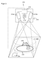
- FIG. 2 shows a second embodiment of the device 110 according to the invention with a two-dimensional safety camera 112, which monitors the working area 114 of a robot 116.
- the security camera 112 has its own display element 118 in the form of a display, on which in FIG. 2 an exemplary state is displayed ("On").
- the attachment of the security camera 112 is shown schematically by a tripod 120, but it could just as well be a mobile camera.
- a luminescent film 122 is attached to the boundary of a protected area, which must not be interfered with because of the movements of the robot 116.
- This luminous film 22 of electroluminescent material can be controlled by the security camera 112 and made to glow.
- the security camera 112 or its evaluation unit 124 recognizes not only interference with the protection area, which leads to a safety-related shutdown, but also in an upstream warning area 126, which surrounds the protection area and in FIG. 2 represented by a dotted, so only virtual line. To facilitate the evaluation, this virtual line can also be provided with a contrast pattern or another luminescent film.
- the evaluation unit 124 activates the luminescent film 122 in order to warn persons against entering the protection area and thereby causing downtimes due to a safety-related shutdown.
- a more complex visual warning can be output.
- This can take the form of a flashing sequence, a color change up to a dynamic color play or a combination.
- the luminous film 122 can also have a plurality of segments which can be driven individually individually, as a result of which the evaluation unit 124 can also generate a pattern. If one combines such a pattern with a blinking sequence, the impression of a circulating barrier or another warning movement can be conveyed. Users are thereby effectively prevented from quickly leaving the warning area 126 and the protected area to be unhurt. All the more so, as the security camera 122 could record the warning and the further behavior of the invaded person to document the non-compliant behavior.
- the warning field 126 and the protective field delimited by the luminous film 122 can be configured by a user, for example by means of a connected computer or an operating element of the camera 112.
- the camera 112 can also teach in a special mode, the limits of the protective field itself by activating the then clearly visible in the camera image luminous film 122.
- the protective field can thus be configured in a simple manner by masking the border with the luminous film 122.
- FIG. 3 a third embodiment of the device 210 according to the invention is shown.
- the security camera 212 used herein is a three-dimensional stereo camera having two camera modules 212a and 212b, an active illumination 214 and an evaluation unit 216, and bird's eye view of a robot 218.
- a protective field is limited by a light film 220, which may be a three-dimensional shelter due to the 3D recording.
- a surrounding warning field 222 is here an example of part of a cylinder jacket.
- the monitoring, in particular the function of the luminous film 220, is quite analogous to the second embodiment.
- Still another light-emitting element 224 is provided, which is mounted on the floor.
- the warning field 222 is intervened, further statuses of the 3D camera 212 can be displayed.
- a display on the camera 212 itself would even be difficult to recognize because of their attachment to the ceiling, if operators ever directed the look there.
- FIG. 4 shows a fourth embodiment 310 of the device according to the invention with a motion detector 312 on a door 314, which opens and closes automatically.
- a motion detector 312 a camera or a laser scanner could be used.
- a protected area here is the one in which the door 314 swings open.
- a luminous foil 316 At the border of this protection area is a luminous foil 316, which is activated by the motion detector 312 when someone approaching the door 314, the criterion being, for example, exceeding the limits of a warning area 318. Otherwise, the mode of operation of the fourth embodiment is analogous to that of the second embodiment.
- the sensors described in connection with the first to fourth embodiments are only to be understood as examples.
- the invention is applicable to any type of optical sensors, ie light grids, laser scanners, security cameras including three-dimensional security cameras, such as time of day cameras or stereo cameras, but also working with non-optical principles, such as capacitive, microwave or radar sensors and finally on non-contact sensors or protective devices addition also touch-sensitive sensors such as safety mats or capacitive touch sensors.
- the information that can be output via a light film is not limited to warnings or limitations of protective fields. Many other states are conceivable, such as “on”, “active”, “light path free”, “light path interrupted”, “warning zone violated”, “protected zone violated”, “approaching an object”, “waiting for cycle” or “maintenance required”. It is also possible to output measurement data, as far as it is manageable by the described colors, patterns or temporal codes by flashing sequences. The various displays can be staggered in their catchability and conspicuousness according to their importance. Thus, for example, an urgent maintenance request would be indicated by large red flashing, a status such as "all OK", however, by turning off or a quiet, little flashy lights shown.
- the individual embodiments may not be understood as exclusive, but the features may be combined with each other.
- the various information to be output, the manner of activating the luminescent film, its mounting and trimming, the connection to a controller via wireless interface and other features are not limited to the sensor described in each case to an embodiment, but can be based on the needs of the application transmit additional sensors.
Landscapes
- Engineering & Computer Science (AREA)
- General Engineering & Computer Science (AREA)
- Mechanical Engineering (AREA)
- Physics & Mathematics (AREA)
- General Physics & Mathematics (AREA)
- Radar, Positioning & Navigation (AREA)
- Remote Sensing (AREA)
- Theoretical Computer Science (AREA)
- Life Sciences & Earth Sciences (AREA)
- General Life Sciences & Earth Sciences (AREA)
- Geophysics (AREA)
- Alarm Systems (AREA)
Abstract
Description
- Die Erfindung betrifft eine Vorrichtung zur Überwachung mit einem Sensorelement und ein Sicherheitsverfahren zur Erkennung eines Eingriffs in einen Überwachungsbereich nach dem Oberbegriff von Anspruch 1 beziehungsweise 10.
- Sensoren jeder Art besitzen üblicherweise eine Anzeige, um Messwerte oder einen Status anzuzeigen. So kann etwa an einem Überwachungssensor eine LCD-Anzeige oder eine Reihe von LEDs vorgesehen sein, welche Meldungen über den Zustand des Sensors oder des Überwachungsbereichs einem Benutzer sichtbar machen. Sie dienen also der Visualisierung des Betriebszustandes oder werden zur Diagnoseunterstützung verwendet. Allerdings sind Sensoren häufig an Stellen verbaut, die nicht leicht zugänglich sind und somit sind die Sensorinformationen für einen Benutzer nicht leicht erkennbar, vor allem, wenn die Sensoren oder auch nur ihre integrierten Anzeigen relativ klein sind.
- Bekannt ist daher auch, für bessere Sichtbarkeit Leuchtmelder anzubauen oder räumlich unabhängige Leuchtmelder mit LEDs oder Lampen zu verwenden. Solche Leuchtmelder verursachen Zusatzkosten in Entwicklung und Herstellung, bedürfen entsprechender Montagevorrichtungen und lassen sich auch nur bedingt an vorliegende Montagebedingungen anpassen.
- Eine besonders wichtige Information über einen Sensor besteht in der Sicherheitstechnik darin, diejenigen Bereiche zu kennen, welche von dem Sensor gegen unberechtigte oder gefährliche Eingriffe durch Personen oder auch Maschinen jeder Art geschützt werden. Solche Schutzbereiche umgeben eine Gefahrenquelle, etwa eine gefährliche Maschine wie eine Presse oder einen Roboter und der Sensor gibt bei Erkennung eines unzulässigen Eingriffs in den Schutzbereich ein Signal aus, welches die Gefahrenquelle absichert. Dies kann durch Abschaltung oder anderweitige Verbringung in einen sicheren Zustand geschehen, wie etwa das Einschwenken einer Schutzvorrichtung.
- Die herkömmlich am häufigsten angewandte Methode, die Gefahrenquelle umgebende Schutzbereiche oder Schutzfelder zu kennzeichnen, besteht darin, die Grenzen mit einem gelb-schwarzen Band abzukleben. Dabei tritt aber in der Praxis ein Gewöhnungseffekt auf und das Band sticht Bedienpersonal nicht mehr ins Auge. Nach dieser Gewöhnungsphase kommt es also doch wieder zu unbeabsichtigten Übergriffen über die Schutzfeldgrenzen.
- Dem eigentlichen Schutzbereich, bei dem auf einen Eingriff hin die sicherheitsgerichtete Abschaltung erfolgt, ist häufig noch ein Warnbereich vorgelagert, der bereits nicht mehr betreten werden soll, aber noch nicht unmittelbar zu einer Gefährdung führt. Dazu können Lautsprecher zur Signalisierung bei Betreten eines Warnbereichs verwendet werden, die jedoch vom Personal als ausgesprochen störend empfunden werden. Dieses Empfinden geht oft so weit, dass versucht wird, die Lautsprecher abzuschalten oder anderweitig unwirksam zu machen.
- Da jeder versehentliche Eingriff in einen Schutzbereich durch Ausfallzeiten Kosten verursacht, werden auch physische Schutzabtrennungen eingesetzt, welche zwar das Personal wirksam vom Schutzbereich abhalten, gegenüber einer Absicherung mittels Sensoren aber sperrig, unflexibel und für viele Arbeitsgänge behindernd sind. Eine Ablösung durch eine sensorbasierte Lösung wird daher oftmals nur in Betracht gezogen, wenn dabei auch das Problem des unbeabsichtigten Eintretens und die Aufrechterhaltung ungestörter Maschinenprozesse beherrscht wird.
- Aus der
EP 1 518 073 B1 ist eine berührungslos wirkende Schutzeinrichtung bekannt, deren Gehäuse selbst das optische Anzeigeelement bildet. Dazu kann es beispielsweise aus einem optisch aktiven Kunststoff bestehen. Nachteilig hieran ist, dass dieses durch das Gehäuse gebildete Anzeigeelement natürlich fest an den Ort des Sensors gebunden bleibt. Wenn der Sensor also an einer schlecht oder nicht einsehbaren Stelle montiert ist, kann auch diese Anzeige nicht gesehen werden. Zudem ist es nicht möglich, bestehende Sensoren umzurüsten, da ein Austausch des Gehäuses in seinem Aufwand nahezu der Neuherstellung eines Sensors gleichkommt. Schließlich ist es aufwändig, Form und Kontur der leuchtenden Bereiche anzupassen und zumindest ist dies nur bei der Herstellung des Gehäuses und nicht mehr bei der Montage möglich. - Aus der
DE 199 38 639 B4 ist eine Vorrichtung zur Absicherung eines Gefahrenbereichs bekannt, welche auf einer Kamera basiert, die einen Reflektorstreifen beobachtet. Dieser Reflektorstreifen oder die Sichtebene von Kamera zu Reflektorstreifen bildet dabei also eine Grenze des Schutzbereichs. Der Reflektorstreifen wird von einer aktiven Beleuchtung der Kamera angeleuchtet, damit diese Grenze besser erkennbar ist. In einer besonderen Ausführungsform kann statt des angeleuchteten Reflektorstreifens eine aktiv leuchtende Folie eingesetzt werden. Diese aktiv leuchtende Folie bildet dabei also effektiv den Sender und die Kamera den Empfänger einer optoelektronischen Schutzvorrichtung. Daher ist es nicht möglich, den Streifen für irgendwelche Anzeigen zu verwenden, denn er muss ständig aktiv leuchtend bleiben, damit die Kamera ihre Schutzfunktion ausüben kann. Der zu dem gelb-schwarzem Klebeband beschriebene Gewöhnungseffekt tritt demnach wegen des immer konstanten Reizes für das Auge des Bedienpersonals auch hier auf. - Aus der
DE 10 2006 013 834 A1 sind elektrolumineszierende Haftklebemassen bekannt, mit denen Klebebänder ausgerüstet werden können. Durch Anlegen einer Spannung können diese Klebebänder zum Leuchten angeregt werden. Die Klebemasse kann bei Anzeigeelementen beispielsweise von Mobiltelefonen, PDAs, Computern oder Monitoren verwendet werden, wo sie zugleich eine Hintergrundbeleuchtung und eine Klebeverbindung für das Anzeigeelement schafft. Ein anderes Einsatzgebiet ist die Verklebung von Notbeleuchtungssystemen und Hinweisschildern in öffentlichen Gebäuden, Krankenhäusern oder Flugzeugen. Eine Zusammenwirkung mit Sensoren ist nicht genannt. Indem Displays unmittelbar mit der Haftklebemasse in das Gerät eingepasst werden, wird auch die Sichtbarkeit gegenüber herkömmlichen Anzeigeelementen nicht erhöht. - Daher ist Aufgabe der Erfindung, ein System zur Überwachung anzugeben, dessen Sensorelement in der Lage ist, eine deutlich sichtbare Anzeige zu erzeugen.
- Diese Aufgabe wird durch eine Vorrichtung nach Anspruch 1, ein Sicherheitsverfahren nach Anspruch 11 und ein Herstellungsverfahren nach Anspruch 15 gelöst.
- Indem erfindungsgemäß Leuchtfolie das Anzeigeelement bildet und ihre Aktivität von dem Sensorelement steuerbar ist, besteht für das Sensorelement die Möglichkeit, Informationen auf einer nahezu beliebig formbaren und überall leicht anbringbaren Anzeige darzustellen. Somit kann das Sensorelement unabhängig von der Sichtbarkeit seiner Anzeigeelemente auch an unzugänglichen Orten montiert werden. Totzonen, in denen ein herkömmliches Anzeigeelement den aktiven Bereich des Sensors verdecken würde, können vermieden werden. Das erfindungsgemäße Anzeigeelement, nämlich die Leuchtfolie, kann leicht an jede Umgebung angepasst und dort montiert werden, indem es nämlich beispielsweise einfach mit einer Schere auf die gewünschte Form zurechtgeschnitten und aufgeklebt wird. Diese Leuchtfolie kann auch eine ästhetische Wirkung erzielen, auf sich aufmerksam machen oder ein Werbeträger sein, etwa als Logo ausgestaltet oder damit versehen. Sie ist aus jeder Richtung gut erkennbar, und da das Sensorelement den Aktivitätszustand ändern kann, kann Gewöhnungseffekten entgegengewirkt werden.
- Die Leuchtfolie ist vorteilhafterweise an dem Sensorelement angebracht, insbesondere an einem Gehäuse des Sensorelements, oder sie ist unabhängig vom Ort des Sensorelements angebracht, insbesondere mit einer Klebeschicht versehen. In der ersten Alternative kann ein herkömmlicher Sensor auf einfachste Weise nachgerüstet werden. Die zweite Alternative kommt immer dann in Betracht, wenn die Anzeige von Standorten, aus Blickwinkeln oder Entfernungen erkannt werden soll, von denen aus das Sensorelement selbst nicht oder nicht ausreichend sichtbar ist.
- Das Sensorelement weist bevorzugt eine Sensorschnittstelle zur Ansteuerung der Leuchtfolie und die Leuchtfolie eine Leuchtfolienschnittstelle zum Empfang einer Ansteuerung von dem Sensorelement auf, wobei die Schnittstellen Ein- und Ausgänge für eine direkte Verbindung oder Schnittstellen für eine drahtlose Kommunikation sind, insbesondere nach dem Bluetooth-, Firewire-, GSM-, WLAN- oder UMTS-Standard. Eine direkte Verbindung über Ausgänge durch eine einfache Leitung oder bei Bedarf auch eine Netz- oder Busanbindung ist zumeist kostengünstiger, bedarf aber einer räumlichen Nähe und einer möglicherweise störenden physischen Verbindung. Drahtlose Kommunikationsschnittstellen geben dagegen völlige Flexibilität und ermöglichen eine besonders einfache Montage des Anzeigeelements, denn die Leuchtfolie muss weiterhin einfach aufgeklebt werden, ohne sich um eine Verbindung kümmern zu müssen.
- Die Leuchtfolie weist bevorzugt elektrolumineszierendes Material auf, oder sie weist photolumineszierendes Material auf, insbesondere UV-aktivierbar, wobei die Vorrichtung eine Lichtquelle zur Aktivierung der Photolumineszenz aufweist. Derartige Leuchtfolien sind einsatzfertig und kostengünstig erhältlich. Eine photolumineszierende Folie ist noch etwas kostengünstiger und dem Anwender kann nicht der Fehler unterlaufen, beim Zurechtschneiden versehentlich die Anschlussstellen zu beschädigen oder zu entfernen. Dafür muss allerdings eine zusätzliche Lichtquelle, meist eine UV-Lichtquelle, zur Beleuchtung der photolumineszierenden Folie angebracht werden, welche mit dem Sensorelement verbunden ist, damit das Sensorelement die Folie zum Leuchten bringen kann. Eine direkte Deaktivierung ist nur bei der elektrolumineszierenden Folie möglich, da die Photolumineszenz zunächst von selbst abklingen muss.
- Eine Auswertungseinheit des Sensorelements ist bevorzugt dafür ausgebildet, die Statusinformation und/oder den Messwert über die Leuchtfolie durch deren partielle oder vollständige Aktivierung, Deaktivierung oder einen Farbwechsel auszugeben. Dies sind verschiedene Möglichkeiten, den Benutzer je nach Anforderung mehr oder weniger deutlich auf eine Ausgabe des Sensorelements aufmerksam zu machen.
- Dabei ist die Auswertungseinheit besonders bevorzugt insbesondere für eine eindringlichere Ausgabe einer Statusinformation und/oder eines Messwerts dafür ausgebildet, die Leuchtfolie dynamisch zu aktivieren, insbesondere durch eine Blinksequenz, mehrere Farbwechsel und/oder Erzeugung wechselnder Muster mittels Aktivierung von Teilbereichen oder mehreren Leuchtfolien. Damit können Signale betont werden, welche vom Personal eine wichtige oder sofortige Reaktion erfordern. Dies könnte ein drohender Brand sein, die Warnung vor einem Diebstahl oder eine Wartungsanforderung, mit welcher der Sensor anzeigt, dass er derzeit oder in nahe Zukunft nicht oder nicht mehr vollständig einsatzfähig ist.
- In einer vorteilhaften Weiterbildung ist das Sensorelement dafür ausgebildet, als Statusinformation die Annäherung einer Person oder die Verletzung eines definierten Warnfeldes zu erkennen und auszugeben, wobei insbesondere die Leuchtfolie an einer Grenze und/oder in einem Schutzbereich oder Teilbereichen davon angebracht ist und wobei in dem Schutzbereich eine von der Vorrichtung abzusichernde Gefahrenquelle angeordnet ist. Die Vorrichtung kann damit ein dynamisches Signal erzeugen, um Personal vor einem Eindringen in den Schutzbereich wirkungsvoll zu warnen. Dadurch können unnötige Ausfallzeiten verhindert werden. Da das Signal dynamisch ist, je nach Situation in unterschiedlicher Intensität und nur bei einem tatsächlich drohenden Eingriff in das Schutzfeld ausgegeben werden kann, tritt auch nicht der einleitend beschriebene nachteilige Gewöhnungseffekt ein. Schließlich wird eine optische Warnung durch die Leuchtfolie vom Personal als deutlich weniger störend empfunden als das aufdringliche Heulen einer Sirene, so dass weniger Anreiz besteht, die Warnfunktion zu unterlaufen und zur Vermeidung des störenden Signals außer Gefecht zu setzen.
- Das Sensorelement ist bevorzugt dafür ausgebildet, als Statusinformation die Zustände "Ein", "Aktiv", "Lichtweg frei", "Lichtweg unterbrochen", "Warnbereich verletzt", "Schutzbereich verletzt", "Annäherung eines Objekts", "Warten auf Takt" und/oder "Wartung erforderlich" zu erkennen und auszugeben, wobei insbesondere die Zustände durch Dauer einer Aktivierung oder Deaktivierung, Blinksequenzen, Farben, Aktivierung von Teilbereichen oder einer von mehreren Leuchtfolien unterschiedlich codiert sind. Dies ist eine Auswahl von wichtigen möglichen Statusinformationen, welche dem Benutzer durch die Leuchtfolie gut sichtbar vermittelt werden können. Durch die unterschiedlichen Kodierungen kann der Benutzer nicht nur die Statusinformationen voneinander unterscheiden, die Signale können auch in ihrer Intensität gestaffelt werden, so dass wichtigere Statusinformationen dem Benutzer eher auffallen als unwichtigere.
- In Weiterbildung weist die Vorrichtung vorteilhafterweise zusätzlich zu der Leuchtfolie mindestens ein weiteres Anzeigeelement auf, über welches redundant oder alternativ Statusinformationen und/oder Messwerte ausgegeben werden können. Beispielsweise kann ein herkömmlicher Sensor verwendet werden, an den zusätzlich eine Leuchtfolie angeschlossen wird. Die üblichen Bedien- und Anzeigeelemente bleiben dabei erhalten. Andererseits gibt es Statusinformationen und insbesondere Messdaten, deren Informationsdichte sich weniger zur Anzeige per Leuchtfolie eignet.
- Die Vorrichtung ist bevorzugt eine insbesondere optische oder optoelektronische berührungslos wirkende Schutzeinrichtung wie ein Lichtgitter, ein Laserscanner oder eine Sicherheitskamera. Gerade solche Sensoren werden in bestehende oder durch ihre Funktionalität bestimmte Systeme eingebaut, nach- oder umgerüstet und müssen sich flexibel an die Gegebenheiten anpassen können. Zudem dürfen gerade sicherheitsrelevante Statusinformationen nicht übersehen werden, weil dies die Gesundheit von Bedienpersonal gefährden oder zumindest zu teuren Ausfallzeiten führen würde.
- Das erfindungsgemäße Verfahren kann auf ähnliche Weise weitergebildet werden und zeigt dabei ähnliche Vorteile. Derartige vorteilhafte Merkmale sind beispielhaft, aber nicht abschließend in den sich an die unabhängigen Ansprüche anschließenden Unteransprüchen beschrieben.
- Die Erfindung wird nachstehend auch hinsichtlich weiterer Merkmale und Vorteile beispielhaft anhand von Ausführungsformen und unter Bezug auf die beigefügte Zeichnung näher erläutert. Die Abbildungen der Zeichnung zeigen in:
- Fig. 1
- eine erste Ausführungsform der Erfindung mit einem Lichtgitter, einer an dessen Gehäuse angebrachten elektrolumineszierenden Leuchtfolie und einer im Abstand an einer Wand montierten photolumineszierenden Leuchtfolie;
- Fig. 2
- eine zweite Ausführungsform der Erfindung mit einer 2D-Sicherheitskamera, welche seitlich eines Arbeitsbereichs eines Roboters angebracht ist;
- Fig. 3
- eine dritte Ausführungsform der Erfindung mit einer dreidimensionalen Stereoskopiekamera, welche einen Arbeitsbereich eines Roboters aus der Vogelperspektive überwacht; und
- Fig. 4
- eine vierte Ausführungsform der Erfindung mit einem Bewegungsmelder oder einem Scanner zur Überwachung und automatischen Öffnung einer Tür.
-
Figur 1 zeigt eine erste Ausführungsform einer erfindungsgemäßen Vorrichtung 10 zur Überwachung, bei welcher ein Lichtgitter 12 ein Schutzfeld 14 durch mehrere zueinander parallele Lichtstrahlen 16 aufspannt, welche durch die Lichtsender 18 einer ersten Säule 20 und Lichtempfänger 22 einer zweiten Säule 24 des Lichtgitters 12 erzeugt werden. - Hinter dem Lichtsender 12 könnte sich beispielsweise eine gefährliche Maschine, wie eine Abkantpresse oder ein Roboter befinden, in deren Einflussbereich Bedienpersonal zur Vermeidung von Verletzungen nicht kommen darf. Wird einer der Lichtstrahlen 16 unterbrochen, so erkennt dies eine Auswertungseinheit 26 und erzeugt über einen nicht dargestellten Sicherheitsausgang einen Befehl an die Maschine, welcher sie abschaltet oder in eine sichere Position bringt. Damit diese Absicherung unter allen Umständen erfolgen kann, ist die Auswertungseinheit 26 und der Sicherheitsausgang durch zweikanalige Ausführung oder Selbsttests sicher ausgelegt.
- Die erste Säule 20 und die zweite Säule 24 des Lichtgitters 12 können untereinander eine elektrische oder drahtlose Verbindung aufweisen, damit die Auswertungseinheit 26 auch Elemente der zweiten Säule 24 ansteuern kann. Das Lichtgitter 12 weist Anzeigeelemente 28, beispielsweise LEDs auf, um einen Status anzuzeigen.
- Eine Warnanzeige 30 ist mit der Auswertungseinheit 26 verbunden und kann auf diese Weise aktiviert und deaktiviert werden. Die Warnanzeige 30 besteht aus einer elektrolumineszierenden Leuchtfolie, welche also durch Anlegen einer Spannung von der Auswertungseinheit 26 zum Leuchten gebracht werden kann. Die Leuchtfolie kann ab Werk in der benötigten Form zurecht geschnitten sein, oder sie wird aus einer Grundfläche bei der Montage zurecht geschnitten und auf das Gehäuse des Lichtgitters 12 geklebt oder dort in anderer Weise befestigt. Zur vereinfachten Anbringung kann die Leuchtfolie mit einer Klebeschicht versehen sein.
- Die Bedeutung der aktiven Warnanzeige 30 kann beispielsweise darin liegen, dass die durch das Lichtgitter 12 geschützte Maschine bei leuchtender Warnanzeige 30 aktiv ist. Die Warnanzeige 30 kann auch in einer Blinksequenz aktiviert werden, um noch stärker aufzufallen.
- Eine zweite Warnanzeige 32 ist in einigem Abstand an einer Wand 34 angebracht. Im Gegensatz zu der ersten Warnanzeige 30 besteht die zweite Warnanzeige 32 aus einem photoluminesszierenden Material. Durch eine mit der Auswertungseinheit 26 verbundenen Lampe 36, vorzugsweise mit einer Abstrahlung im UV-Bereich, jedenfalls aber abgestimmt auf eine Anregungsfrequenz der photolumineszierenden Folie, kann die zweite Warnanzeige 34 zum Leuchten gebracht werden. Dies kann gleichzeitig mit, aber auch unabhängig von der ersten Warnanzeige 30 geschehen und denselben oder einen anderen Status des Lichtgitters 12 anzeigen. Die Warnanzeige 32 ist auch von Standpunkten gut sichtbar, wo das Lichtgitter 12 und dessen Warnanzeige 30 bzw. dessen LEDs 28 nicht gesehen werden können.
- Es versteht sich von selbst, dass beide Warnanzeigen 30, 32 in weiteren Ausführungsformen unabhängig vom Ort ihrer Anbringung nach Bedarf aus elektrolumineszierendem oder photoluminesszierendem Material gebildet werden können.
- Die Ansteuerungsleitung der Warnanzeige 30 bzw. der Lampe 36 kann eine drahtgebundene direkte, serielle oder Ethernetverbindung sein. Wegen des geringeren Aufwands und der Vermeidung störender Leitungen kann alternativ eine drahtlose Kommunikationsschnittstelle der Auswertungseinheit 26 mit einer Spannungsversorgung an der elektrolumineszierenden Folie der Warnanzeige 30 beziehungsweise der Lampe 36 verbunden sein. Dann muss jeweils eine lokale Energieversorgung in Form eines Anschlusses, einer Batterie oder eines Akkus vorhanden sein, welche im Falle der drahtgebunden Anbindung von der Auswertungseinheit 26 geleistet werden kann.
-
Figur 2 zeigt eine zweite Ausführungsform der erfindungsgemäßen Vorrichtung 110 mit einer zweidimensionalen Sicherheitskamera 112, welche den Arbeitsbereich 114 eines Roboters 116 überwacht. Die Sicherheitskamera 112 besitzt ein eigenes Anzeigenelement 118 in Form eines Displays, auf dem inFigur 2 ein beispielhafter Zustand angezeigt wird ("On"). Die Anbringung der Sicherheitskamera 112 ist schematisch durch ein Stativ 120 dargestellt, sie könnte aber ebenso gut eine mobile Kamera sein. - Eine Leuchtfolie 122 ist an der Grenze eines Schutzbereiches angebracht, in den wegen der Bewegungen des Roboters 116 nicht eingegriffen werden darf. Diese Leuchtfolie 22 aus elektrolumineszierendem Material kann von der Sicherheitskamera 112 angesteuert und zum Leuchten gebracht werden.
- Die Sicherheitskamera 112 beziehungsweise ihre Auswertungseinheit 124 erkennt nicht nur Eingriffe in den Schutzbereich, welche zu einer sicherheitsgerichteten Abschaltung führen, sondern auch in einen vorgelagerten Warnbereich 126, welcher den Schutzbereich umgibt und in
Figur 2 durch eine gepunktete, also nur virtuelle Linie dargestellt ist. Zur Erleichterung der Auswertung kann diese virtuelle Linie auch mit einem Kontrastmuster oder einer weiteren Leuchtfolie versehen werden. - Bei einem solchen Eingriff in den Warnbereich 126 aktiviert die Auswertungseinheit 124 die Leuchtfolie 122, um Personen davor zu warnen, den Schutzbereich zu betreten und dadurch Ausfallzeiten durch eine sicherheitsgerichtete Abschaltung zu verursachen.
- Um Gewöhnungseffekten entgegenzuwirken, kann statt einer einfachen Aktivierung der Leuchtfolie 122 eine komplexere optische Warnung ausgegeben werden. Diese kann die Form einer Blinksequenz, eines Farbwechsels bis hin zu einem dynamischen Farbspiel oder einer Kombination annehmen. Die Leuchtfolie 122 kann auch mehrere elektrisch einzeln ansteuerbare Segmente aufweisen, wodurch die Auswertungseinheit 124 auch ein Muster erzeugen kann. Kombiniert man etwa ein solches Muster mit einer Blinksequenz, so kann der Eindruck einer umlaufenden Barriere oder einer anderen warnenden Bewegung vermittelt werden. Benutzer werden dadurch wirkungsvoll dazu angehalten, den Warnbereich 126 rasch wieder zu verlassen und den Schutzbereich unverletzt zu lassen. Dies umso mehr, als die Sicherheitskamera 122 die Warnung und das weitere Verhalten der eingedrungenen Person aufzeichnen könnte, um das nicht vorschriftsgemäße Verhalten zu dokumentieren.
- Das Warnfeld 126 und das von der Leuchtfolie 122 begrenzte Schutzfeld kann, beispielsweise per angeschlossenem Computer oder einem Bedienelement der Kamera 112, von einem Benutzer konfiguriert werden. Die Kamera 112 kann aber auch in einem besonderen Modus die Grenzen des Schutzfeldes selber durch Aktivierung der im Kamerabild dann gut erkennbaren Leuchtfolie 122 einlernen. Das Schutzfeld kann so auf einfache Weise durch Abkleben der Grenze mit der Leuchtfolie 122 konfiguriert werden.
- In
Figur 3 ist eine dritte Ausführungsform der erfindungsgemäßen Vorrichtung 210 dargestellt. Diese Ausführungsform unterscheidet sich von der zweiten Ausführungsform darin, dass die hier verwendete Sicherheitskamera 212 eine dreidimensionale Stereokamera ist, welche zwei Kameramodule 212a und 212b, eine aktive Beleuchtung 214 und eine Auswertungseinheit 216 aufweist und einen Roboter 218 aus der Vogelperspektive überwacht. Auch hier wird ein Schutzfeld von einer Leuchtfolie 220 begrenzt, welches aufgrund der 3D-Aufnahme ein dreidimensionaler Schutzraum sein kann. Ein umgebendes Warnfeld 222 ist hier beispielhaft Teil eines Zylindermantels. Die Überwachung, insbesondere die Funktion der Leuchtfolie 220, ist ganz analog der zweiten Ausführungsform. - Zusätzlich ist noch ein weiteres Leuchtfolienelement 224 vorgesehen, welches auf dem Boden angebracht ist. Dadurch können zusätzlich zu einem optischen Kenntlichmachen mittels der Leuchtfolie 220, wenn in das Warnfeld 222 eingegriffen wird, noch weitere Status der 3D-Kamera 212 angezeigt werden. Eine Anzeige an der Kamera 212 selbst wäre wegen deren Anbringung an der Decke sogar dann noch schlecht zu erkennen, wenn Bedienpersonal überhaupt den Blick dorthin richtet.
-
Figur 4 zeigt eine vierte Ausführungsform 310 der erfindungsgemäßen Vorrichtung mit einem Bewegungsmelder 312 an einer Tür 314, welche sich automatisch öffnet und schließt. Anstelle eines Bewegungsmelders 312 könnte eine Kamera oder ein Laserscanner eingesetzt werden. Ein zu schützender Bereich ist hier derjenige, in den die Tür 314 aufschwingt. An der Grenze dieses Schutzbereichs ist eine Leuchtfolie 316 angebracht, welche von dem Bewegungsmelder 312 aktiviert wird, wenn sich jemand der Tür 314 nähert, wobei das Kriterium beispielsweise die Überschreitung der Grenzen eines Warnbereichs 318 sein könnte. Ansonsten ist auch die Funktionsweise der vierten Ausführungsform derjenigen der zweiten Ausführungsform analog. - Die im Zusammenhang mit der ersten bis vierten Ausführungsform beschriebenen Sensoren sind jeweils nur exemplarisch zu verstehen. Die Erfindung ist für jegliche Art von optischen Sensoren anwendbar, also Lichtgitter, Laserscanner, Sicherheitskameras einschließlich dreidimensionaler Sicherheitskameras, wie Lichtlaufzeitkameras oder Stereokameras, aber auch mit nicht optischen Prinzipien arbeitende, beispielsweise kapazitive, Mikrowellen- oder Radarsensoren und schließlich über berührungslos wirkende Sensoren oder Schutzeinrichtungen hinaus auch auf Berührung reagierende Sensoren wie Schaltmatten oder kapazitive Berührungssensoren.
- Ebenso sind die Informationen, welche über eine Leuchtfolie ausgegeben werden können, nicht auf Warnungen oder Begrenzungen von Schutzfeldern beschränkt. So sind viele weitere Status denkbar, etwa "Ein", "Aktiv", "Lichtweg frei", "Lichtweg unterbrochen", "Warnbereich verletzt", "Schutzbereich verletzt", "Annäherung eines Objekts", "Warten auf Takt" oder "Wartung erforderlich". Es können auch Messdaten ausgegeben werden, soweit das durch die beschriebenen Farben, Muster oder zeitlichen Codierungen durch Blinksequenzen handhabbar ist. Die verschiedenen Anzeigen können in ihrer Warnehmbarkeit und Auffälligkeit anhand ihrer Wichtigkeit gestaffelt werden. So würde beispielsweise eine dringende Wartungsanforderung durch großflächiges, rotes Blinken angezeigt, ein Status wie "alles OK" hingegen durch Ausschalten oder ein ruhiges, wenig auffälliges Leuchten dargestellt.
- Schließlich dürfen die einzelnen Ausführungsformen nicht ausschließend verstanden werden, sondern die Merkmale können untereinander kombiniert werden. Die verschiedenen auszugebenden Informationen, die Art der Aktivierung der Leuchtfolie, ihre Montage und das Zurechtschneiden, die Anbindung an eine Steuerung per drahtloser Schnittstelle und weitere Merkmale sind nicht auf den jeweils zu einer Ausführungsform beschriebenen Sensor beschränkt, sondern lassen sich je nach Bedarf der Anwendung auf weitere Sensoren übertragen.
Claims (16)
- Vorrichtung (10, 110, 210, 310) zur Überwachung, insbesondere Sicherheitssensor (12, 112, 212), mit einem Sensorelement (12, 112, 212, 312) zur Erkennung eines Eingriffs in einen Überwachungsbereich oder einer Annäherung an das Sensorelement (12, 112, 212, 312), einem Anzeigeelement (30, 32, 122, 220, 316) für die Anzeige einer Statusinformation und/oder eines Messwerts sowie mit einer aktiven oder aktivierbaren Leuchtfolie,
dadurch gekennzeichnet,
dass die Leuchtfolie das Anzeigeelement (30, 32, 122, 220, 316) bildet und die Aktivität der Leuchtfolie von dem Sensorelement (12, 112, 212, 312) steuerbar ist. - Vorrichtung (10, 110, 210, 310) nach Anspruch 1,
wobei die Leuchtfolie (30) an dem Sensorelement (12, 112, 212, 312) angebracht ist, insbesondere an einem Gehäuse des Sensorelements (12, 112, 212, 312), oder wobei die Leuchtfolie (32, 122, 220, 316) unabhängig vom Ort des Sensorelements (12, 112, 212, 312) angebracht werden kann, insbesondere mit einer Klebeschicht versehen ist. - Vorrichtung (10, 110, 210, 310) nach Anspruch 1 oder 2,
wobei das Sensorelement (12, 112, 212, 312) eine Sensorschnittstelle zur Ansteuerung der Leuchtfolie (30, 32, 122, 220, 316) und die Leuchtfolie (30, 32, 122, 220, 316) eine Leuchtfolienschnittstelle zum Empfang einer Ansteuerung von dem Sensorelement (12, 112, 212, 312) aufweist, wobei die Schnittstellen Ein- und Ausgänge für eine direkte Verbindung oder Schnittstellen für eine drahtlose Kommunikation sind, insbesondere nach dem Bluetooth-, Firewire-, GSM-, WLAN- oder UMTS-Standard. - Vorrichtung (10, 110, 210, 310) nach einem der vorhergehenden Ansprüche,
wobei die Leuchtfolie (30, 122, 220, 316) elektrolumineszierendes Material aufweist, oder wobei die Leuchtfolie (32) photolumineszierendes Material aufweist, insbesondere UV-aktivierbar, und wobei die Vorrichtung eine Lichtquelle (36) zur Aktivierung der Photolumineszenz aufweist. - Vorrichtung (10, 110, 210, 310) nach einem der vorhergehenden Ansprüche,
wobei eine Auswertungseinheit (26, 124, 216) des Sensorelements (12, 112, 212, 312) dafür ausgebildet ist, die Statusinformation und/oder den Messwert über die Leuchtfolie (30, 32, 122, 220, 316) durch deren partielle oder vollständige Aktivierung, Deaktivierung oder einen Farbwechsel auszugeben. - Vorrichtung (10, 110, 210, 310) nach Anspruch 5,
wobei die Auswertungseinheit (26, 124, 216) insbesondere für eine eindringlichere Ausgabe einer Statusinformation und/oder eines Messwerts dafür ausgebildet ist, die Leuchtfolie (30, 32, 122, 220, 316) dynamisch zu aktivieren, insbesondere durch eine Blinksequenz, mehrere Farbwechsel und/oder Erzeugung wechselnder Muster mittels Aktivierung von Teilbereichen oder mehreren Leuchtfolien (30, 32, 122, 220, 316). - Vorrichtung (10, 110, 210, 310) nach einem der vorhergehenden Ansprüche,
wobei das Sensorelement (12, 112, 212, 312) dafür ausgebildet ist, als Statusinformation die Annäherung einer Person oder die Verletzung eines definierten Warnfeldes (126, 222, 318) zu erkennen und auszugeben, wobei insbesondere die Leuchtfolie (30, 32, 122, 220, 316) an einer Grenze und/oder in einem Schutzbereich oder Teilbereichen davon angebracht ist, wobei in dem Schutzbereich eine von der Vorrichtung abzusichernde Gefahrenquelle angeordnet ist. - Vorrichtung (10, 110, 210, 310) nach einem der vorhergehenden Ansprüche,
wobei das Sensorelement (12, 112, 212, 312) dafür ausgebildet ist, als Statusinformation die Zustände "Ein", "Aktiv", "Lichtweg frei", "Lichtweg unterbrochen", "Warnbereich verletzt", "Schutzbereich verletzt", "Annäherung eines Objekts", "Warten auf Takt" und/oder "Wartung erforderlich" zu erkennen und auszugeben, wobei insbesondere die Zustände durch Dauer einer Aktivierung oder Deaktivierung, Blinksequenzen, Farben, Aktivierung von Teilbereichen oder einer von mehreren Leuchtfolien (30, 32, 122, 220, 316) unterschiedlich codiert sind. - Vorrichtung (10, 110, 210, 310) nach einem der vorhergehenden Ansprüche,
wobei die Vorrichtung (10, 110, 210, 310) zusätzlich zu der Leuchtfolie (30, 32, 122, 220, 316) mindestens ein weiteres Anzeigeelement (28, 118, 224) aufweist, über welches redundant oder alternativ Statusinformationen und/oder Messwerte ausgegeben werden können. - Vorrichtung (10, 110, 210, 310) nach einem der vorhergehenden Ansprüche, die eine insbesondere optische oder optoelektronische berührungslos wirkende Schutzeinrichtung wie ein Lichtgitter (12), ein Laserscanner (312) oder Sicherheitskamera (112, 212) ist.
- Sicherheitsverfahren zur Erkennung eines Eingriffs in einen Überwachungsbereich oder einer Annäherung an ein Sensorelement (12, 112, 212, 312), wobei eine Statusinformation und/oder ein Messwert angezeigt wird,
dadurch gekennzeichnet,
dass die Statusinformation und/oder der Messwert über eine aktive oder aktivierbare Leuchtfolie (30, 32, 122, 220, 316) angezeigt wird. - Verfahren nach Anspruch 11,
wobei die Statusinformation und/oder der Messwert drahtlos von dem Sensorelement (12, 112, 212, 312) zu der Leuchtfolie (30, 32, 122, 220, 316) übertragen wird, insbesondere nach dem Bluetooth-, Firewire-, GSM-, WLAN- oder UMTS-Standard. - Verfahren nach Anspruch 11 oder 12,
wobei die Statusinformation und/oder der Messwert durch eine partielle oder vollständige Aktivierung, Deaktivierung oder einen Farbwechsel der Leuchtfolie (30, 32, 122, 220, 316) ausgegeben wird und wobei insbesondere für eine eindringlichere Ausgabe einer Statusinformation und/oder eines Messwerts die Leuchtfolie (30, 32, 122, 220, 316) dynamisch aktiviert wird, insbesondere durch eine Blinksequenz, mehrere Farbwechsel und/oder Erzeugung wechselnder Muster mittels Aktivierung von Teilbereichen oder mehreren Leuchtfolien (30, 32, 122, 220, 316). - Verfahren nach einem der Ansprüche 11 bis 13,
wobei als Statusinformation die Annäherung einer Person oder die Verletzung eines definierten Warnfeldes (126, 222, 318) erkannt und ausgegeben wird,
wobei insbesondere die Leuchtfolie (30, 32, 122, 220, 316) an einer Grenze und/oder in einem Schutzbereich, in dem eine abzusichernde Gefahrenquelle angeordnet ist, oder in Teilbereichen des Schutzbereichs angebracht wird. - Verfahren zur Herstellung einer Vorrichtung (10, 110, 210, 310) nach einem der Ansprüche 1 bis 10, wobei ein Sensorelement (12, 112, 212, 312) derart an einem Überwachungsbereich angeordnet wird, dass Annäherungen an das Sensorelement (12, 112, 212, 312) oder Eingriffe in den Überwachungsbereich erkannt werden können, eine Leuchtfolie (30, 32, 122, 220, 316) an einem Gehäuse des Sensorelements (12, 112, 212, 312), einer gut einsehbaren Fläche oder an einer Grenze oder innerhalb eines Schutzbereichs oder in Teilen davon angebracht oder aufgeklebt wird, und wobei eine drahtgebundene oder drahtlose Verbindung zwischen dem Sensorelement (12, 112, 212, 312) und der Leuchtfolie (30, 32, 122, 220, 316) geschaffen wird.
- Verfahren nach Anspruch 15,
wobei eine Leuchtfolie (30, 122, 220, 316) verwendet wird, die elektrolumineszierendes Material aufweist, und wobei die Verbindung von dem Sensorelement (12, 112, 212, 312) zu der Leuchtfolie (30, 122, 220, 316) selbst geschaffen wird, oder wobei eine Leuchtfolie (32) verwendet wird, die photolumineszierendes Material aufweist, insbesondere UV-aktivierbar, und wobei eine Lichtquelle (36), welche die Photolumineszenz aktivieren kann, derart angebracht wird, dass sie die Leuchtfolie (32) beleuchten kann und die Verbindung von dem Sensorelement (12, 112, 212, 312) zu der Lichtquelle (36) geschaffen wird.
Priority Applications (2)
| Application Number | Priority Date | Filing Date | Title |
|---|---|---|---|
| AT08101797T ATE537526T1 (de) | 2008-02-20 | 2008-02-20 | Überwachung mit einem sensorelement |
| EP08101797A EP2093725B1 (de) | 2008-02-20 | 2008-02-20 | Überwachung mit einem Sensorelement |
Applications Claiming Priority (1)
| Application Number | Priority Date | Filing Date | Title |
|---|---|---|---|
| EP08101797A EP2093725B1 (de) | 2008-02-20 | 2008-02-20 | Überwachung mit einem Sensorelement |
Publications (2)
| Publication Number | Publication Date |
|---|---|
| EP2093725A1 true EP2093725A1 (de) | 2009-08-26 |
| EP2093725B1 EP2093725B1 (de) | 2011-12-14 |
Family
ID=40084391
Family Applications (1)
| Application Number | Title | Priority Date | Filing Date |
|---|---|---|---|
| EP08101797A Not-in-force EP2093725B1 (de) | 2008-02-20 | 2008-02-20 | Überwachung mit einem Sensorelement |
Country Status (2)
| Country | Link |
|---|---|
| EP (1) | EP2093725B1 (de) |
| AT (1) | ATE537526T1 (de) |
Cited By (2)
| Publication number | Priority date | Publication date | Assignee | Title |
|---|---|---|---|---|
| DE102011054806B4 (de) | 2011-10-26 | 2022-08-25 | Leuze Electronic Gmbh & Co. Kg | Ausrichthilfe für einen Sensor |
| DE102023109423A1 (de) * | 2023-04-14 | 2024-10-17 | Kardex Produktion Deutschland Gmbh | Sicherheitssystem für ein automatisches Lagersystem und ein automatisches Lagersystem |
Citations (11)
| Publication number | Priority date | Publication date | Assignee | Title |
|---|---|---|---|---|
| US4514725A (en) * | 1982-12-20 | 1985-04-30 | Bristley Barbara E | Window shade mounted alarm system |
| DE19938639A1 (de) * | 1999-08-14 | 2001-02-22 | Pilz Gmbh & Co | Vorrichtung zur Absicherung eines Gefahrenbereichs, insbesondere des Gefahrenbereichs einer automatisiert arbeitenden Maschine |
| EP1306603A2 (de) | 2001-10-24 | 2003-05-02 | Sick Ag | Verfahren und Vorrichtung zum Steuern einer sicherheitsrelevanten Funktion einer Maschine |
| DE202004012836U1 (de) * | 2004-08-15 | 2004-12-09 | Schwarz, Rainer | Standortanzeige für Feuerlöscheinrichtungen mittels Leuchtfolien |
| DE10355023A1 (de) | 2003-11-25 | 2004-12-23 | Daimlerchrysler Ag | Vorrichtung zum Abdecken einer Fahrzeugoberfläche |
| DE10345197A1 (de) * | 2003-09-29 | 2005-04-21 | Bsh Bosch Siemens Hausgeraete | Haushaltgerät mit einer Vorrichtung zur Lieferung von Benutzerinformation und/oder von Umfeldbeleuchtungen |
| EP1518073B1 (de) * | 2002-06-18 | 2006-04-26 | Sick Ag | Sensor |
| DE102005011143A1 (de) | 2005-03-10 | 2006-09-14 | Sick Ag | Vorrichtung und Verfahren zum Steuern einer sicherheitsrelevanten Funktion |
| DE202006015495U1 (de) | 2006-10-09 | 2007-02-01 | Degussa Ag | Elektrolumineszent ausgestattete Artikel |
| DE202006018787U1 (de) | 2006-12-11 | 2007-04-05 | J.H. Tönnjes GmbH & Co. KG | Schild, insbesondere Hinweisschild |
| EP1788535A1 (de) * | 2005-11-18 | 2007-05-23 | Almat AG | Vorrichtung zum Signalisieren eines Notausganges in einem Tunnel oder dergleichen |
-
2008
- 2008-02-20 AT AT08101797T patent/ATE537526T1/de active
- 2008-02-20 EP EP08101797A patent/EP2093725B1/de not_active Not-in-force
Patent Citations (11)
| Publication number | Priority date | Publication date | Assignee | Title |
|---|---|---|---|---|
| US4514725A (en) * | 1982-12-20 | 1985-04-30 | Bristley Barbara E | Window shade mounted alarm system |
| DE19938639A1 (de) * | 1999-08-14 | 2001-02-22 | Pilz Gmbh & Co | Vorrichtung zur Absicherung eines Gefahrenbereichs, insbesondere des Gefahrenbereichs einer automatisiert arbeitenden Maschine |
| EP1306603A2 (de) | 2001-10-24 | 2003-05-02 | Sick Ag | Verfahren und Vorrichtung zum Steuern einer sicherheitsrelevanten Funktion einer Maschine |
| EP1518073B1 (de) * | 2002-06-18 | 2006-04-26 | Sick Ag | Sensor |
| DE10345197A1 (de) * | 2003-09-29 | 2005-04-21 | Bsh Bosch Siemens Hausgeraete | Haushaltgerät mit einer Vorrichtung zur Lieferung von Benutzerinformation und/oder von Umfeldbeleuchtungen |
| DE10355023A1 (de) | 2003-11-25 | 2004-12-23 | Daimlerchrysler Ag | Vorrichtung zum Abdecken einer Fahrzeugoberfläche |
| DE202004012836U1 (de) * | 2004-08-15 | 2004-12-09 | Schwarz, Rainer | Standortanzeige für Feuerlöscheinrichtungen mittels Leuchtfolien |
| DE102005011143A1 (de) | 2005-03-10 | 2006-09-14 | Sick Ag | Vorrichtung und Verfahren zum Steuern einer sicherheitsrelevanten Funktion |
| EP1788535A1 (de) * | 2005-11-18 | 2007-05-23 | Almat AG | Vorrichtung zum Signalisieren eines Notausganges in einem Tunnel oder dergleichen |
| DE202006015495U1 (de) | 2006-10-09 | 2007-02-01 | Degussa Ag | Elektrolumineszent ausgestattete Artikel |
| DE202006018787U1 (de) | 2006-12-11 | 2007-04-05 | J.H. Tönnjes GmbH & Co. KG | Schild, insbesondere Hinweisschild |
Cited By (2)
| Publication number | Priority date | Publication date | Assignee | Title |
|---|---|---|---|---|
| DE102011054806B4 (de) | 2011-10-26 | 2022-08-25 | Leuze Electronic Gmbh & Co. Kg | Ausrichthilfe für einen Sensor |
| DE102023109423A1 (de) * | 2023-04-14 | 2024-10-17 | Kardex Produktion Deutschland Gmbh | Sicherheitssystem für ein automatisches Lagersystem und ein automatisches Lagersystem |
Also Published As
| Publication number | Publication date |
|---|---|
| ATE537526T1 (de) | 2011-12-15 |
| EP2093725B1 (de) | 2011-12-14 |
Similar Documents
| Publication | Publication Date | Title |
|---|---|---|
| EP2558886B1 (de) | Einrichtung zur überwachung mindestens eines dreidimensionalen sicherheitsbereichs | |
| DE102011106838B4 (de) | Außenrückspiegel mit Leuchtanzeige und Verfahren zur Darstellung kritischer Verkehrssituationen | |
| EP1339561B1 (de) | Anordnung zur überwachung des umfelds eines fahrzeugs | |
| EP2695009B1 (de) | Leuchtvorrichtung mit 3d-wirkung | |
| WO2014023405A1 (de) | Steuerungsverfahren und steuerungssystem für ein fahrzeugschliesselement | |
| EP2902995B1 (de) | Leuchte | |
| DE20106977U1 (de) | Warneinrichtung in Kraftfahrzeugen | |
| WO2005101092A1 (de) | Signalisiervorrichtung zur anzeige von warn- und/oder informationshinweisen in fahrzeugen | |
| EP2936467A1 (de) | Überwachen einer gefahrenzone | |
| WO2018103878A1 (de) | Verfahren zur visualisierung eines fahrzustandes | |
| DE10358177B4 (de) | Optische Anzeigevorrichtung für ein Fahrerassistenzsystem | |
| EP2093725B1 (de) | Überwachung mit einem Sensorelement | |
| EP4418056B1 (de) | Bedieneinheit und verfahren zum bedienen einer anlage mit einer bedieneinheit | |
| DE102023125389A1 (de) | Industrieleuchte | |
| EP1361115B1 (de) | Verfahren zum Betreiben eines Fahrzeugumfeldüberwachungssystems und Umfeldüberwachungssystem | |
| DE102013110762B3 (de) | Warnschild-Vorrichtung für Falschfahrer | |
| EP1518073B1 (de) | Sensor | |
| DE102024003938B3 (de) | Verfahren zum Betreiben einer Beleuchtungsvorrichtung | |
| DE10055297A1 (de) | Verfahren zur rhythmischen udn unrhythmischen Veränderung der Lichtintensität | |
| DE10261621A1 (de) | Vorrichtung zur Überwachung der toten Winkel eines Kraftfahrzeugs | |
| EP4388517A1 (de) | Hinweiszeicheneinheit, warnsystem und verfahren zum betreiben eines warnsystems | |
| EP2473888B1 (de) | Bediengerät mit anzeige | |
| EP4388516A1 (de) | Hinweiszeicheneinheit, warnsystem und verfahren zum betreiben eines warnsystems | |
| DE102021124113A1 (de) | Hinweiszeicheneinheit, Warnsystem und Verfahren zum Betreiben eines Warnsystems | |
| WO2023041721A1 (de) | Hinweiszeicheneinheit, warnsystem und verfahren zum betreiben eines warnsystems |
Legal Events
| Date | Code | Title | Description |
|---|---|---|---|
| PUAI | Public reference made under article 153(3) epc to a published international application that has entered the european phase |
Free format text: ORIGINAL CODE: 0009012 |
|
| 17P | Request for examination filed |
Effective date: 20090316 |
|
| AK | Designated contracting states |
Kind code of ref document: A1 Designated state(s): AT BE BG CH CY CZ DE DK EE ES FI FR GB GR HR HU IE IS IT LI LT LU LV MC MT NL NO PL PT RO SE SI SK TR |
|
| AX | Request for extension of the european patent |
Extension state: AL BA MK RS |
|
| 17Q | First examination report despatched |
Effective date: 20090901 |
|
| AKX | Designation fees paid |
Designated state(s): AT BE BG CH CY CZ DE DK EE ES FI FR GB GR HR HU IE IS IT LI LT LU LV MC MT NL NO PL PT RO SE SI SK TR |
|
| GRAP | Despatch of communication of intention to grant a patent |
Free format text: ORIGINAL CODE: EPIDOSNIGR1 |
|
| GRAS | Grant fee paid |
Free format text: ORIGINAL CODE: EPIDOSNIGR3 |
|
| GRAA | (expected) grant |
Free format text: ORIGINAL CODE: 0009210 |
|
| AK | Designated contracting states |
Kind code of ref document: B1 Designated state(s): AT BE BG CH CY CZ DE DK EE ES FI FR GB GR HR HU IE IS IT LI LT LU LV MC MT NL NO PL PT RO SE SI SK TR |
|
| REG | Reference to a national code |
Ref country code: GB Ref legal event code: FG4D Free format text: NOT ENGLISH |
|
| REG | Reference to a national code |
Ref country code: CH Ref legal event code: EP |
|
| REG | Reference to a national code |
Ref country code: IE Ref legal event code: FG4D |
|
| REG | Reference to a national code |
Ref country code: DE Ref legal event code: R096 Ref document number: 502008005834 Country of ref document: DE Effective date: 20120209 |
|
| REG | Reference to a national code |
Ref country code: NL Ref legal event code: VDEP Effective date: 20111214 |
|
| PG25 | Lapsed in a contracting state [announced via postgrant information from national office to epo] |
Ref country code: NO Free format text: LAPSE BECAUSE OF FAILURE TO SUBMIT A TRANSLATION OF THE DESCRIPTION OR TO PAY THE FEE WITHIN THE PRESCRIBED TIME-LIMIT Effective date: 20120314 Ref country code: LT Free format text: LAPSE BECAUSE OF FAILURE TO SUBMIT A TRANSLATION OF THE DESCRIPTION OR TO PAY THE FEE WITHIN THE PRESCRIBED TIME-LIMIT Effective date: 20111214 |
|
| LTIE | Lt: invalidation of european patent or patent extension |
Effective date: 20111214 |
|
| PG25 | Lapsed in a contracting state [announced via postgrant information from national office to epo] |
Ref country code: HR Free format text: LAPSE BECAUSE OF FAILURE TO SUBMIT A TRANSLATION OF THE DESCRIPTION OR TO PAY THE FEE WITHIN THE PRESCRIBED TIME-LIMIT Effective date: 20111214 Ref country code: SI Free format text: LAPSE BECAUSE OF FAILURE TO SUBMIT A TRANSLATION OF THE DESCRIPTION OR TO PAY THE FEE WITHIN THE PRESCRIBED TIME-LIMIT Effective date: 20111214 Ref country code: SE Free format text: LAPSE BECAUSE OF FAILURE TO SUBMIT A TRANSLATION OF THE DESCRIPTION OR TO PAY THE FEE WITHIN THE PRESCRIBED TIME-LIMIT Effective date: 20111214 Ref country code: NL Free format text: LAPSE BECAUSE OF FAILURE TO SUBMIT A TRANSLATION OF THE DESCRIPTION OR TO PAY THE FEE WITHIN THE PRESCRIBED TIME-LIMIT Effective date: 20111214 Ref country code: GR Free format text: LAPSE BECAUSE OF FAILURE TO SUBMIT A TRANSLATION OF THE DESCRIPTION OR TO PAY THE FEE WITHIN THE PRESCRIBED TIME-LIMIT Effective date: 20120315 Ref country code: LV Free format text: LAPSE BECAUSE OF FAILURE TO SUBMIT A TRANSLATION OF THE DESCRIPTION OR TO PAY THE FEE WITHIN THE PRESCRIBED TIME-LIMIT Effective date: 20111214 |
|
| PG25 | Lapsed in a contracting state [announced via postgrant information from national office to epo] |
Ref country code: CY Free format text: LAPSE BECAUSE OF FAILURE TO SUBMIT A TRANSLATION OF THE DESCRIPTION OR TO PAY THE FEE WITHIN THE PRESCRIBED TIME-LIMIT Effective date: 20111214 |
|
| REG | Reference to a national code |
Ref country code: IE Ref legal event code: FD4D |
|
| PG25 | Lapsed in a contracting state [announced via postgrant information from national office to epo] |
Ref country code: IE Free format text: LAPSE BECAUSE OF FAILURE TO SUBMIT A TRANSLATION OF THE DESCRIPTION OR TO PAY THE FEE WITHIN THE PRESCRIBED TIME-LIMIT Effective date: 20111214 Ref country code: SK Free format text: LAPSE BECAUSE OF FAILURE TO SUBMIT A TRANSLATION OF THE DESCRIPTION OR TO PAY THE FEE WITHIN THE PRESCRIBED TIME-LIMIT Effective date: 20111214 Ref country code: CZ Free format text: LAPSE BECAUSE OF FAILURE TO SUBMIT A TRANSLATION OF THE DESCRIPTION OR TO PAY THE FEE WITHIN THE PRESCRIBED TIME-LIMIT Effective date: 20111214 Ref country code: IS Free format text: LAPSE BECAUSE OF FAILURE TO SUBMIT A TRANSLATION OF THE DESCRIPTION OR TO PAY THE FEE WITHIN THE PRESCRIBED TIME-LIMIT Effective date: 20120414 Ref country code: BG Free format text: LAPSE BECAUSE OF FAILURE TO SUBMIT A TRANSLATION OF THE DESCRIPTION OR TO PAY THE FEE WITHIN THE PRESCRIBED TIME-LIMIT Effective date: 20120314 Ref country code: EE Free format text: LAPSE BECAUSE OF FAILURE TO SUBMIT A TRANSLATION OF THE DESCRIPTION OR TO PAY THE FEE WITHIN THE PRESCRIBED TIME-LIMIT Effective date: 20111214 |
|
| BERE | Be: lapsed |
Owner name: SICK A.G. Effective date: 20120228 |
|
| PG25 | Lapsed in a contracting state [announced via postgrant information from national office to epo] |
Ref country code: PL Free format text: LAPSE BECAUSE OF FAILURE TO SUBMIT A TRANSLATION OF THE DESCRIPTION OR TO PAY THE FEE WITHIN THE PRESCRIBED TIME-LIMIT Effective date: 20111214 Ref country code: RO Free format text: LAPSE BECAUSE OF FAILURE TO SUBMIT A TRANSLATION OF THE DESCRIPTION OR TO PAY THE FEE WITHIN THE PRESCRIBED TIME-LIMIT Effective date: 20111214 Ref country code: PT Free format text: LAPSE BECAUSE OF FAILURE TO SUBMIT A TRANSLATION OF THE DESCRIPTION OR TO PAY THE FEE WITHIN THE PRESCRIBED TIME-LIMIT Effective date: 20120416 |
|
| PG25 | Lapsed in a contracting state [announced via postgrant information from national office to epo] |
Ref country code: MC Free format text: LAPSE BECAUSE OF NON-PAYMENT OF DUE FEES Effective date: 20120229 |
|
| PLBE | No opposition filed within time limit |
Free format text: ORIGINAL CODE: 0009261 |
|
| STAA | Information on the status of an ep patent application or granted ep patent |
Free format text: STATUS: NO OPPOSITION FILED WITHIN TIME LIMIT |
|
| PG25 | Lapsed in a contracting state [announced via postgrant information from national office to epo] |
Ref country code: DK Free format text: LAPSE BECAUSE OF FAILURE TO SUBMIT A TRANSLATION OF THE DESCRIPTION OR TO PAY THE FEE WITHIN THE PRESCRIBED TIME-LIMIT Effective date: 20111214 |
|
| 26N | No opposition filed |
Effective date: 20120917 |
|
| PG25 | Lapsed in a contracting state [announced via postgrant information from national office to epo] |
Ref country code: IT Free format text: LAPSE BECAUSE OF FAILURE TO SUBMIT A TRANSLATION OF THE DESCRIPTION OR TO PAY THE FEE WITHIN THE PRESCRIBED TIME-LIMIT Effective date: 20111214 |
|
| PG25 | Lapsed in a contracting state [announced via postgrant information from national office to epo] |
Ref country code: BE Free format text: LAPSE BECAUSE OF NON-PAYMENT OF DUE FEES Effective date: 20120228 |
|
| REG | Reference to a national code |
Ref country code: DE Ref legal event code: R097 Ref document number: 502008005834 Country of ref document: DE Effective date: 20120917 |
|
| PG25 | Lapsed in a contracting state [announced via postgrant information from national office to epo] |
Ref country code: ES Free format text: LAPSE BECAUSE OF FAILURE TO SUBMIT A TRANSLATION OF THE DESCRIPTION OR TO PAY THE FEE WITHIN THE PRESCRIBED TIME-LIMIT Effective date: 20120325 |
|
| PG25 | Lapsed in a contracting state [announced via postgrant information from national office to epo] |
Ref country code: FI Free format text: LAPSE BECAUSE OF FAILURE TO SUBMIT A TRANSLATION OF THE DESCRIPTION OR TO PAY THE FEE WITHIN THE PRESCRIBED TIME-LIMIT Effective date: 20111214 |
|
| PG25 | Lapsed in a contracting state [announced via postgrant information from national office to epo] |
Ref country code: MT Free format text: LAPSE BECAUSE OF FAILURE TO SUBMIT A TRANSLATION OF THE DESCRIPTION OR TO PAY THE FEE WITHIN THE PRESCRIBED TIME-LIMIT Effective date: 20111214 |
|
| REG | Reference to a national code |
Ref country code: AT Ref legal event code: MM01 Ref document number: 537526 Country of ref document: AT Kind code of ref document: T Effective date: 20130220 |
|
| PG25 | Lapsed in a contracting state [announced via postgrant information from national office to epo] |
Ref country code: TR Free format text: LAPSE BECAUSE OF FAILURE TO SUBMIT A TRANSLATION OF THE DESCRIPTION OR TO PAY THE FEE WITHIN THE PRESCRIBED TIME-LIMIT Effective date: 20111214 |
|
| PG25 | Lapsed in a contracting state [announced via postgrant information from national office to epo] |
Ref country code: LU Free format text: LAPSE BECAUSE OF NON-PAYMENT OF DUE FEES Effective date: 20120220 Ref country code: AT Free format text: LAPSE BECAUSE OF NON-PAYMENT OF DUE FEES Effective date: 20130220 |
|
| PGFP | Annual fee paid to national office [announced via postgrant information from national office to epo] |
Ref country code: FR Payment date: 20140218 Year of fee payment: 7 |
|
| PGFP | Annual fee paid to national office [announced via postgrant information from national office to epo] |
Ref country code: GB Payment date: 20140220 Year of fee payment: 7 |
|
| PG25 | Lapsed in a contracting state [announced via postgrant information from national office to epo] |
Ref country code: HU Free format text: LAPSE BECAUSE OF FAILURE TO SUBMIT A TRANSLATION OF THE DESCRIPTION OR TO PAY THE FEE WITHIN THE PRESCRIBED TIME-LIMIT Effective date: 20080220 |
|
| GBPC | Gb: european patent ceased through non-payment of renewal fee |
Effective date: 20150220 |
|
| REG | Reference to a national code |
Ref country code: FR Ref legal event code: ST Effective date: 20151030 |
|
| PG25 | Lapsed in a contracting state [announced via postgrant information from national office to epo] |
Ref country code: GB Free format text: LAPSE BECAUSE OF NON-PAYMENT OF DUE FEES Effective date: 20150220 |
|
| PG25 | Lapsed in a contracting state [announced via postgrant information from national office to epo] |
Ref country code: FR Free format text: LAPSE BECAUSE OF NON-PAYMENT OF DUE FEES Effective date: 20150302 |
|
| PGFP | Annual fee paid to national office [announced via postgrant information from national office to epo] |
Ref country code: CH Payment date: 20160222 Year of fee payment: 9 |
|
| REG | Reference to a national code |
Ref country code: CH Ref legal event code: PL |
|
| PG25 | Lapsed in a contracting state [announced via postgrant information from national office to epo] |
Ref country code: CH Free format text: LAPSE BECAUSE OF NON-PAYMENT OF DUE FEES Effective date: 20170228 Ref country code: LI Free format text: LAPSE BECAUSE OF NON-PAYMENT OF DUE FEES Effective date: 20170228 |
|
| PGFP | Annual fee paid to national office [announced via postgrant information from national office to epo] |
Ref country code: DE Payment date: 20190219 Year of fee payment: 12 |
|
| REG | Reference to a national code |
Ref country code: DE Ref legal event code: R119 Ref document number: 502008005834 Country of ref document: DE |
|
| PG25 | Lapsed in a contracting state [announced via postgrant information from national office to epo] |
Ref country code: DE Free format text: LAPSE BECAUSE OF NON-PAYMENT OF DUE FEES Effective date: 20200901 |