EP2093411B1 - Kupplungsvorrichtung - Google Patents
Kupplungsvorrichtung Download PDFInfo
- Publication number
- EP2093411B1 EP2093411B1 EP08003043A EP08003043A EP2093411B1 EP 2093411 B1 EP2093411 B1 EP 2093411B1 EP 08003043 A EP08003043 A EP 08003043A EP 08003043 A EP08003043 A EP 08003043A EP 2093411 B1 EP2093411 B1 EP 2093411B1
- Authority
- EP
- European Patent Office
- Prior art keywords
- fuel injector
- fuel
- ring element
- screw thread
- coupling device
- Prior art date
- Legal status (The legal status is an assumption and is not a legal conclusion. Google has not performed a legal analysis and makes no representation as to the accuracy of the status listed.)
- Expired - Fee Related
Links
Images


Classifications
-
- F—MECHANICAL ENGINEERING; LIGHTING; HEATING; WEAPONS; BLASTING
- F02—COMBUSTION ENGINES; HOT-GAS OR COMBUSTION-PRODUCT ENGINE PLANTS
- F02M—SUPPLYING COMBUSTION ENGINES IN GENERAL WITH COMBUSTIBLE MIXTURES OR CONSTITUENTS THEREOF
- F02M55/00—Fuel-injection apparatus characterised by their fuel conduits or their venting means; Arrangements of conduits between fuel tank and pump F02M37/00
- F02M55/004—Joints; Sealings
-
- F—MECHANICAL ENGINEERING; LIGHTING; HEATING; WEAPONS; BLASTING
- F02—COMBUSTION ENGINES; HOT-GAS OR COMBUSTION-PRODUCT ENGINE PLANTS
- F02M—SUPPLYING COMBUSTION ENGINES IN GENERAL WITH COMBUSTIBLE MIXTURES OR CONSTITUENTS THEREOF
- F02M55/00—Fuel-injection apparatus characterised by their fuel conduits or their venting means; Arrangements of conduits between fuel tank and pump F02M37/00
- F02M55/02—Conduits between injection pumps and injectors, e.g. conduits between pump and common-rail or conduits between common-rail and injectors
- F02M55/025—Common rails
-
- F—MECHANICAL ENGINEERING; LIGHTING; HEATING; WEAPONS; BLASTING
- F02—COMBUSTION ENGINES; HOT-GAS OR COMBUSTION-PRODUCT ENGINE PLANTS
- F02M—SUPPLYING COMBUSTION ENGINES IN GENERAL WITH COMBUSTIBLE MIXTURES OR CONSTITUENTS THEREOF
- F02M69/00—Low-pressure fuel-injection apparatus ; Apparatus with both continuous and intermittent injection; Apparatus injecting different types of fuel
- F02M69/46—Details, component parts or accessories not provided for in, or of interest apart from, the apparatus covered by groups F02M69/02 - F02M69/44
- F02M69/462—Arrangement of fuel conduits, e.g. with valves for maintaining pressure in the pipes after the engine being shut-down
- F02M69/465—Arrangement of fuel conduits, e.g. with valves for maintaining pressure in the pipes after the engine being shut-down of fuel rails
-
- F—MECHANICAL ENGINEERING; LIGHTING; HEATING; WEAPONS; BLASTING
- F02—COMBUSTION ENGINES; HOT-GAS OR COMBUSTION-PRODUCT ENGINE PLANTS
- F02M—SUPPLYING COMBUSTION ENGINES IN GENERAL WITH COMBUSTIBLE MIXTURES OR CONSTITUENTS THEREOF
- F02M2200/00—Details of fuel-injection apparatus, not otherwise provided for
- F02M2200/85—Mounting of fuel injection apparatus
- F02M2200/856—Mounting of fuel injection apparatus characterised by mounting injector to fuel or common rail, or vice versa
Definitions
- the invention relates to a coupling device for hydraulically and mechanically coupling a fuel injector to a fuel rail of a combustion engine.
- Coupling devices for hydraulically and mechanically coupling a fuel injector to a fuel rail are in widespread use, in particular for internal combustion engines. Fuel can be supplied to an internal combustion engine by the fuel rail assembly through the fuel injector.
- Known fuel rails comprise a hollow body with recesses in form of fuel injector cups, wherein the fuel injectors are arranged.
- the connection of the fuel injectors to the fuel injector cups that supply the fuel from a fuel tank via a low or high-pressure fuel pump needs to be very precise to get a correct injection angle and a sealing of the fuel.
- GB 2 024 937 A discloses a fuel injection system for internal combustion engines comprising a metallic fuel distributor pipe, at least one metallic branch duct in communication with the fuel distributor pipe, and a plurality of fuel injection valves, the or each duct being connectible with a respective one of the fuel injection valves by threaded means.
- EP 1 818 535 A1 discloses a coupling device for connecting an injector to a fluid supply.
- the coupling device comprises a pipe and a connector.
- the pipe communicates with the fluid supply and has a convex end face.
- the coupling device comprises a mounting device which is fixed to the pipe and comprises a coupling body.
- the coupling body comprises a coupling nut and the pipe has a corresponding thread for the coupling nut and the coupling nut is screwed onto the pipe at the thread of the pipe.
- the object of the invention is to create a coupling device for hydraulically and mechanically coupling a fuel injector to a fuel rail which is simply to be manufactured and which facilitates a reliable and precise connection between the fuel injector and the fuel injector cup without a resting of the fuel injector on the cylinder head.
- the invention is distinguished by a coupling device for hydraulically and mechanically coupling a fuel injector to a fuel rail of a combustion engine.
- the coupling device comprises a fuel injector cup having a central longitudinal axis and being designed to be hydraulically coupled to the fuel rail and to engage a fuel inlet portion of the fuel injector, a first ring element being coupled to the fuel injector cup in a way to prevent a movement of the first ring element relative to the fuel injector cup in direction of the central longitudinal axis and the first ring element comprising a first screw thread, and a second ring element being coupled to the fuel injector in a way to prevent a movement of the second ring element relative to the fuel injector in direction of the central longitudinal axis and the second ring element comprising a second screw thread being in engagement with the first screw thread to retain the fuel injector in the fuel injector cup in direction of the central longitudinal axis.
- One of the ring elements is designed to be rotatable around the central longitudinal axis relative to the fuel injector and/or the fuel injector cup.
- Snap rings are arranged on axially opposing ends of the second ring element and are designed to enable positive fitting couplings between the snap rings and the fuel injector in axial direction and are designed to prevent a movement of the second ring element relative to the fuel injector in direction of the central longitudinal axis.
- the first screw thread is a female screw thread and the second screw thread is a male screw thread. This may allow a simple and compact construction of the coupling device which enables to carry out a fast and secure but reversible coupling of the fuel injector to the fuel injector cup.
- the first ring element is in one part with the fuel injector cup.
- This has the advantage that a simple and compact construction of the fuel injector cup is possible. Furthermore, a very secure coupling of the fuel injector to the fuel injector cup is possible. Additionally, a simple machining of the first ring element together with the fuel injector cup is possible.
- the second ring element comprises a collar extending in radial direction. This allows a good accessibility of the coupling device. Consequently, a simple handling for assembling and disassembling the coupling device is possible, in particular if the collar has a larger radial extension as the first ring element.
- a fuel feed device 10 is assigned to an internal combustion engine 22 ( figure 1 ) which can be a diesel engine or a gasoline engine. It includes a fuel tank 12 that is connected via a first fuel line to a fuel pump 14. The output of the fuel pump 14 is connected to a fuel inlet 16 of a fuel rail 18. In the fuel rail 18, the fuel is stored for example under a pressure of about 200 bar in the case of a gasoline engine or of about 2,000 bar in the case of a diesel engine. Fuel injectors 20 are connected to the fuel rail 18 and the fuel is fed to the fuel injectors 20 via the fuel rail 18.
- FIG. 2 shows the fuel injector 20 in detail.
- the fuel injector 20 has a fuel injector body 21 and is suitable for injecting fuel into a combustion chamber of the internal combustion engine 22.
- the fuel injector 20 has a fuel inlet portion 24 and a fuel outlet portion 25.
- the fuel inlet portion 24 of the fuel injector 20 comprises a sealing ring 48 with an outer surface 49.
- the fuel injector 20 comprises a valve needle 26 taken in a cavity 29 of the fuel injector body 21.
- an injection nozzle 28 is formed which is closed or opened by an axial movement of the valve needle 26. In a closing position a fuel flow through the injection nozzle 28 is prevented. In an opening position fuel can flow through the injection nozzle 28 into the combustion chamber of the internal combustion engine 22.
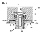
- FIGS 2 and 3 show a coupling device 50 and the fuel injector 20.
- the coupling device 50 is designed to be coupled to the fuel rail 18 of the internal combustion engine 22.
- the coupling device 50 has a fuel injector cup 30, a first ring element 36 and a second ring element 38.
- the fuel injector cup 30 is in one piece with the first ring element 36.
- the fuel injector cup 30 has a recess 34 with an inner surface 32.
- the recess 34 of the fuel injector cup 30 has an inner diameter D1 and is designed to take up the fuel inlet portion 24 of the fuel injector 20.
- the recess 34 is hydraulically coupled to the fuel rail 18 ( figure 1 ).
- Figure 3 shows the fuel injector cup 30 being in engagement with the fuel inlet portion 24 of the fuel injector 20.
- the first ring element 36 is in one piece with the fuel injector cup 30.
- the first ring element 36 has a first screw thread 44 which is a female screw thread and has an inner diameter D2.
- the inner diameter D2 of the first ring element 36 is equal to or larger than the inner diameter D1 of the recess 34 of the fuel injector cup 30.
- the second ring element 38 is coupled to the fuel injector 20.
- the second ring element 38 has a second screw thread 46 being a male screw thread.
- the fuel injector 20 has grooves 27.
- a first snap ring 40 is arranged in one of the grooves 27 of the fuel injector 20 and a second snap ring 42 is arranged in a further groove 27 of the fuel injector 20.
- the grooves 27 are positioned relative to the second ring element 38 in a way that the first snap ring 40 is positioned at a first axial end 39a of the second ring element 38 and the second snap ring 42 is positioned at a second axial end 39b of the second ring element 38.
- the snap rings 40, 42 are arranged on opposing axial ends 39a, 39b of the second ring element 38 the snap rings 40, 42 enable a positive fitting coupling between the second ring element 38 and the fuel injector 20 to prevent an axial movement of the second ring element 38 relative to the fuel injector 20.
- the second ring element 38 is in a slide contact with the fuel injector 20. This enables a rotational movement of the second ring element 38 relative to the fuel injector 20.
- the snap rings 40, 42 comprise anti-rotation elements which enable to position the fuel injector 20 in a defined angular orientation relative to combustions chambers of the combustion engine 22.
- Figure 3 shows the assembled coupling device 50.
- the first ring element 36 is fixedly coupled to the fuel injector cup 30
- the second ring element 38 is coupled to the fuel injector 20 and the first screw thread 44 in an engagement with the second screw thread 46, the fuel injector 20 is retained in the fuel injector cup 30 in direction of the central longitudinal axes L.
- the second ring element 38 has a collar 38a which extends in radial direction from the central longitudinal axis L.
- the collar 38a allows a good manipulation of the second ring element 38. Consequently, a good processing for assembling and disassembling the second ring element 38 from the first ring element 36 is enabled.
- FIG. 3 shows the coupling device 50 after the mounting of the fuel injector cup 30 to the fuel injector 20.
- a positive fitting coupling of the fuel injector cup 30 with the fuel injector 20 can be obtained. Furthermore, the inner surface 32 of the fuel injector cup 30 is in a sealing engagement with the outer surface 49 of the sealing ring 48 of the fuel injector 20. After the assembly process fuel can flow through the fuel injector cup 30 into the fuel inlet portion 24 of the fuel injector 20 without fuel leakage.
- the second ring element 38 is unscrewed from the first ring element 36 by a rotational movement of the second ring element 38 around the central longitudinal axis L relative to the fuel injector 20.
- the threads 44, 46 of the first ring element 36 and the second ring element 38 come out of engagement with each other.
- the fuel injector cup 30 can be shifted away from the fuel injector 20 in axial direction and the fuel injector cup 30 and the fuel injector 20 can be separated from each other.
- the coupling of the fuel injector 20 with the fuel rail 18 by the ring elements 36, 38 allows an assembly of the fuel injector 20 and the fuel injector cup 30 without a further metallic contact between the fuel injector 20 and the further parts of the internal combustion engine 22.
- a sealing between the fuel injector body 21 and a combustion chamber of the internal combustion engine 22 can be carried out by a plastic element, in particular by a PTFE element. Consequently, noise transmission between the fuel injector 20 and further parts of the internal combustion engine can be kept small.
Claims (4)
- Verbindungsvorrichtung (50) zum hydraulischen und mechanischen Verbinden einer Kraftstoffeinspritzvorrichtung (20) mit einem Kraftstoffrail (18) einer Brennkraftmaschine (22), wobei die Verbindungseinrichtung (50) umfasst- ein becherförmiges Element (30) für eine Kraftstoffeinspritzvorrichtung, das eine zentrale Längsachse (L) aufweist und so ausgebildet ist, dass es mit dem Kraftstoffrail (18) hydraulisch verbunden und mit einem Kraftstoffeinlassabschnitt (24) der Kraftstoffeinspritzvorrichtung (20) in Eingriff gebracht werden kann,- ein erstes Ringelement (36), das mit dem becherförmigen Element (30) für die Kraftstoffeinspritzvorrichtung so verbunden ist, dass es eine Bewegung des ersten Ringelementes (36) relativ zum becherförmigen Element (30) für die Kraftstoffeinspritzvorrichtung in Richtung der zentralen Längsachse (L) verhindert, und das ein erstes Schraubengewinde (44) aufweist, und- ein zweites Ringelement (38), das mit der Kraftstoffeinspritzvorrichtung (20) so verbunden ist, dass es eine Bewegung des zweiten Ringelementes (38) relativ zur Kraftstoffeinspritzvorrichtung (20) in Richtung der zentralen Längsachse (L) verhindert, und das ein zweites Schraubengewinde (44) besitzt, das mit dem ersten Schraubengewinde (44) in Eingriff steht, um die Kraftstoffeinspritzvorrichtung (20) im becherförmigen Element (30) für die Kraftstoffeinspritzvorrichtung in Richtung der zentralen Längsachse (L) zu halten, wobeieines der Ringelemente (36) so ausgebildet ist, dass es um die zentrale Längsachse (L) relativ zur Kraftstoffeinspritzvorrichtung (20) und/oder zum becherförmigen Element (30) für die Kraftstoffeinspritzvorrichtung drehbar ist,
dadurch gekennzeichnet, dass
Sicherungsringe (40,42) auf axial gegenüberliegenden Enden (39a, 39b) des zweiten Ringelementes (38) angeordnet und so ausgebildet sind, dass sie formschlüssige Verbindungen zwischen den Sicherungsringen (40,42) und der Kraftstoffeinspritzvorrichtung (20) in axialer Richtung ermöglichen, und so ausgebildet sind, dass sie eine Bewegung des zweiten Ringelementes (38) relativ zur Kraftstoffeinspritzvorrichtung (20) in Richtung der zentralen Längsachse (L) verhindern. - Verbindungsvorrichtung (50) nach Anspruch 1, bei der das erste Schraubengewinde (44) ein Innengewinde und das zweite Schraubengewinde (46) ein Außengewinde ist.
- Verbindungsvorrichtung (50) nach einem der vorangehenden Ansprüche, bei der das erste Ringelement (36) einteilig mit dem becherförmigen Element (30) für die Kraftstoffeinspritzvorrichtung ausgebildet ist.
- Verbindungsvorrichtung (50) nach Anspruch 1, bei der das zweite Ringelement (38) eine Manschette (38a) aufweist, die sich in radialer Richtung erstreckt.
Priority Applications (3)
| Application Number | Priority Date | Filing Date | Title |
|---|---|---|---|
| DE602008004620T DE602008004620D1 (de) | 2008-02-19 | 2008-02-19 | Kupplungsvorrichtung |
| EP08003043A EP2093411B1 (de) | 2008-02-19 | 2008-02-19 | Kupplungsvorrichtung |
| US12/371,744 US7976073B2 (en) | 2008-02-19 | 2009-02-16 | Coupling device |
Applications Claiming Priority (1)
| Application Number | Priority Date | Filing Date | Title |
|---|---|---|---|
| EP08003043A EP2093411B1 (de) | 2008-02-19 | 2008-02-19 | Kupplungsvorrichtung |
Publications (2)
| Publication Number | Publication Date |
|---|---|
| EP2093411A1 EP2093411A1 (de) | 2009-08-26 |
| EP2093411B1 true EP2093411B1 (de) | 2011-01-19 |
Family
ID=39639059
Family Applications (1)
| Application Number | Title | Priority Date | Filing Date |
|---|---|---|---|
| EP08003043A Expired - Fee Related EP2093411B1 (de) | 2008-02-19 | 2008-02-19 | Kupplungsvorrichtung |
Country Status (3)
| Country | Link |
|---|---|
| US (1) | US7976073B2 (de) |
| EP (1) | EP2093411B1 (de) |
| DE (1) | DE602008004620D1 (de) |
Families Citing this family (11)
| Publication number | Priority date | Publication date | Assignee | Title |
|---|---|---|---|---|
| US7942132B2 (en) * | 2008-07-17 | 2011-05-17 | Robert Bosch Gmbh | In-line noise filtering device for fuel system |
| EP2246555B1 (de) | 2009-04-20 | 2012-07-18 | Continental Automotive GmbH | Kupplungsvorrichtung und Kraftstoffeinspritzanordnung |
| EP2388468B1 (de) | 2010-05-18 | 2013-04-10 | Continental Automotive GmbH | Kupplungsvorrichtung |
| AU2011274313B2 (en) * | 2010-06-30 | 2015-05-07 | Orbital Australia Pty Ltd | Fuel injection assembly |
| EP2753820B1 (de) * | 2011-09-08 | 2016-10-19 | Continental Automotive GmbH | Kraftstoffeinspritzanordnung |
| US20140345709A1 (en) * | 2013-05-21 | 2014-11-27 | Continental Automotive Systems, Inc. | Mounting configuration for valve assembly |
| DE102015217673A1 (de) | 2015-09-15 | 2017-03-16 | Continental Automotive Gmbh | Einspritzvorrichtung zur Zumessung eines Fluids und Kraftfahrzeug mit einer derartigen Einspritzvorrichtung |
| US10502112B2 (en) * | 2017-09-14 | 2019-12-10 | Vitesco Technologies USA, LLC | Injector for reductant delivery unit having fluid volume reduction assembly |
| US10677210B2 (en) * | 2017-11-30 | 2020-06-09 | Cfr Engines Canada Ulc | Air-assisted fuel injection system for ignition quality determination |
| US10947880B2 (en) | 2018-02-01 | 2021-03-16 | Continental Powertrain USA, LLC | Injector for reductant delivery unit having fluid volume reduction assembly |
| US11454200B2 (en) | 2019-11-08 | 2022-09-27 | Delphi Technologies Ip Limited | Fuel system with an arrangement which seals between a fuel injector and a fuel rail socket |
Family Cites Families (44)
| Publication number | Priority date | Publication date | Assignee | Title |
|---|---|---|---|---|
| US749496A (en) * | 1904-01-12 | And herbert stew | ||
| US2950130A (en) * | 1957-09-05 | 1960-08-23 | Schneider Richard | Fluid pressure responsive pipe coupling having identical halves |
| US3260539A (en) * | 1965-02-10 | 1966-07-12 | Donald E Herron | Coupling for fluid conduits |
| US3908621A (en) * | 1973-04-25 | 1975-09-30 | Ambac Ind | Hydraulically loaded injector nozzle |
| DE2653674A1 (de) * | 1976-11-26 | 1978-06-01 | Bosch Gmbh Robert | Einspritzventil fuer eine brennkraftmaschine |
| DE2829057A1 (de) | 1978-07-01 | 1980-01-10 | Bosch Gmbh Robert | Kraftstoffeinspritzanlage |
| US4213564A (en) * | 1978-07-17 | 1980-07-22 | Hulsing Kenneth L | Fuel injector |
| JPH0196464A (ja) | 1987-10-07 | 1989-04-14 | Mazda Motor Corp | エンジンの燃料噴射装置 |
| FR2637021B1 (fr) | 1988-09-23 | 1993-12-03 | Peugeot Automobiles | Dispositif de regulation de la pression du carburant d'un moteur a injection, presentant une grande facilite de montage et de demontage |
| KR100301383B1 (ko) * | 1996-07-18 | 2002-07-03 | 오카메 히로무 | 연료분사장치 |
| US5765534A (en) * | 1996-12-10 | 1998-06-16 | Caterpillar Inc. | Loading absorbing jumper tube assembly |
| DE19735665A1 (de) * | 1997-06-25 | 1999-01-07 | Bosch Gmbh Robert | Brennstoffeinspritzanlage |
| DE19727543A1 (de) * | 1997-06-28 | 1999-01-07 | Bosch Gmbh Robert | Kraftstoffzuleitungseinrichtung |
| GB9727421D0 (en) * | 1997-12-30 | 1998-02-25 | Perkins Ltd | Apparatus and method for connecting a fuel pressure tube to a fuel injector of an internal combustion engine |
| DE19941054A1 (de) * | 1999-08-28 | 2001-03-01 | Bosch Gmbh Robert | Kraftstoffeinspritzventil für Brennkraftmaschinen |
| DE19941770A1 (de) | 1999-09-02 | 2001-03-15 | Bosch Gmbh Robert | Rücklaufeinrichtung |
| JP4619598B2 (ja) | 1999-09-10 | 2011-01-26 | インターナショナル エンジン インテレクチュアル プロパティー カンパニー リミテッド ライアビリティ カンパニー | 燃料噴射器用の作動流体送出しシステム |
| DE50013384D1 (de) * | 1999-11-19 | 2006-10-12 | Crt Common Rail Tech Ag | Hochdruckeinspritzsystem mit Common Rail |
| KR100581577B1 (ko) * | 2000-03-21 | 2006-05-22 | 지멘스 악티엔게젤샤프트 | 연료 분사기 조립체 |
| DE10056038A1 (de) * | 2000-11-11 | 2002-05-16 | Bosch Gmbh Robert | Brennstoffeinspritzanlage |
| US6481420B2 (en) * | 2001-01-30 | 2002-11-19 | Visteon Global Technologies, Inc. | Method and apparatus for maintaining the alignment of a fuel injector |
| DE10108203A1 (de) | 2001-02-21 | 2002-08-29 | Bosch Gmbh Robert | Montagebügel und Verfahren zur Montage eines Brennstoffeinspritzventils |
| DE10136050A1 (de) * | 2001-07-25 | 2003-02-13 | Bosch Gmbh Robert | Verfahren zur Herstellung eines Kraftstoffzuteilers mit integrierten Einspritzventilen |
| DE10152421A1 (de) | 2001-10-24 | 2003-06-18 | Bosch Gmbh Robert | Befestigungsvorrichtung |
| DE10156021A1 (de) * | 2001-11-15 | 2003-06-26 | Bosch Gmbh Robert | Brennstoffeinspritzanlage |
| DE10157010A1 (de) * | 2001-11-21 | 2003-06-05 | Bosch Gmbh Robert | Brennstoffeinspritzanlage |
| JP3997946B2 (ja) * | 2002-07-26 | 2007-10-24 | 株式会社デンソー | 燃料供給装置 |
| FR2852636B1 (fr) | 2003-03-19 | 2005-06-17 | Peugeot Citroen Automobiles Sa | Dispositif d'injection de carburant pour moteur a combustion interne, notamment d'un vehicule automobile. |
| FR2872252B1 (fr) * | 2004-06-25 | 2008-03-14 | Senior Automotive Blois Sas So | Dispositif de connexion |
| DE102004037117B4 (de) * | 2004-07-30 | 2013-05-29 | Dr. Ing. H.C. F. Porsche Aktiengesellschaft | Einspritzventil sowie ein Verfahren zur Befestigung dieses Einspritzventils an einer Brennkraftmaschine |
| DE102005020380A1 (de) | 2005-05-02 | 2006-11-09 | Robert Bosch Gmbh | Brennstoffeinspritzvorrichtung |
| DE102005024044A1 (de) | 2005-05-25 | 2006-11-30 | Robert Bosch Gmbh | Vorrichtung zur Befestigung eines Kraftstoff einspritzenden Injektors an einer Brennkraftmaschine |
| EP1806528B1 (de) * | 2006-01-05 | 2008-07-09 | NORMA Germany GmbH | Verbindungsanordnung mit Rohrstutzen zum Verbinden von Fluidaufnahmeteilen |
| EP1818535B1 (de) | 2006-02-08 | 2008-09-17 | Siemens Aktiengesellschaft | Verbindungsanordnung zum Verbinden eines Injektors mit einer Fluid-Versorgung |
| US7334571B1 (en) * | 2006-08-31 | 2008-02-26 | Gm Global Technology Operations, Inc. | Isolation system for high pressure spark ignition direct injection fuel delivery components |
| KR100754501B1 (ko) * | 2007-01-03 | 2007-09-03 | 우양호 | 탈·부착이 용이한 배관의 이음구 |
| US20080169364A1 (en) * | 2007-01-11 | 2008-07-17 | Zdroik Michael J | Welded fuel injector attachment |
| US7445252B2 (en) * | 2007-01-29 | 2008-11-04 | Ying Yeeh Enterprise Co., Ltd. | Connecting device |
| US7516735B1 (en) * | 2008-01-16 | 2009-04-14 | Millennium Industries | Attachment for fuel injectors in a fuel delivery system |
| EP2093412B1 (de) * | 2008-02-19 | 2011-01-19 | Continental Automotive GmbH | Kupplungsvorrichtung |
| DE602008004428D1 (de) * | 2008-02-19 | 2011-02-24 | Continental Automotive Gmbh | Kupplungsvorrichtung |
| US20100012093A1 (en) * | 2008-07-18 | 2010-01-21 | Pepperine Dean M | High-pressure fuel injector to fuel rail connection |
| EP2148082B1 (de) * | 2008-07-24 | 2011-10-19 | Continental Automotive GmbH | Kupplungsanordnung für ein Einspritzventil und Einspritzventil |
| BRPI1007301A2 (pt) * | 2009-02-02 | 2016-02-10 | Tenneco Automotive Operating | sistema de montagem de injetor |
-
2008
- 2008-02-19 EP EP08003043A patent/EP2093411B1/de not_active Expired - Fee Related
- 2008-02-19 DE DE602008004620T patent/DE602008004620D1/de active Active
-
2009
- 2009-02-16 US US12/371,744 patent/US7976073B2/en not_active Expired - Fee Related
Also Published As
| Publication number | Publication date |
|---|---|
| DE602008004620D1 (de) | 2011-03-03 |
| US20090230677A1 (en) | 2009-09-17 |
| EP2093411A1 (de) | 2009-08-26 |
| US7976073B2 (en) | 2011-07-12 |
Similar Documents
| Publication | Publication Date | Title |
|---|---|---|
| EP2093411B1 (de) | Kupplungsvorrichtung | |
| EP2093413B1 (de) | Kupplungsvorrichtung | |
| EP2093412B1 (de) | Kupplungsvorrichtung | |
| EP2375052B1 (de) | Kraftstoffeinspritzanordnung | |
| EP2103804B1 (de) | Kupplungsanordnung | |
| US7934488B2 (en) | Coupling device | |
| EP2208883B1 (de) | Kupplungsvorrichtung | |
| EP2246555B1 (de) | Kupplungsvorrichtung und Kraftstoffeinspritzanordnung | |
| EP2241746A1 (de) | Kupplungsvorrichtung | |
| EP2753820B1 (de) | Kraftstoffeinspritzanordnung | |
| EP2241745B1 (de) | Kupplungsvorrichtung | |
| US10030619B2 (en) | Connector for mounting sensor in pressurized fluid system | |
| EP2090772B1 (de) | Verbindungsanordnung | |
| EP2388468B1 (de) | Kupplungsvorrichtung | |
| KR101948936B1 (ko) | 유체 주입 장치 | |
| EP3470661A1 (de) | Kraftstoffverteileranordnung für einen verbrennungsmotor und verfahren zu deren herstellung | |
| EP2292920B1 (de) | Kupplungsvorrichtung |
Legal Events
| Date | Code | Title | Description |
|---|---|---|---|
| PUAI | Public reference made under article 153(3) epc to a published international application that has entered the european phase |
Free format text: ORIGINAL CODE: 0009012 |
|
| AK | Designated contracting states |
Kind code of ref document: A1 Designated state(s): AT BE BG CH CY CZ DE DK EE ES FI FR GB GR HR HU IE IS IT LI LT LU LV MC MT NL NO PL PT RO SE SI SK TR |
|
| AX | Request for extension of the european patent |
Extension state: AL BA MK RS |
|
| 17P | Request for examination filed |
Effective date: 20100226 |
|
| AKX | Designation fees paid |
Designated state(s): DE FR IT |
|
| GRAP | Despatch of communication of intention to grant a patent |
Free format text: ORIGINAL CODE: EPIDOSNIGR1 |
|
| GRAS | Grant fee paid |
Free format text: ORIGINAL CODE: EPIDOSNIGR3 |
|
| GRAA | (expected) grant |
Free format text: ORIGINAL CODE: 0009210 |
|
| AK | Designated contracting states |
Kind code of ref document: B1 Designated state(s): DE FR IT |
|
| REF | Corresponds to: |
Ref document number: 602008004620 Country of ref document: DE Date of ref document: 20110303 Kind code of ref document: P |
|
| REG | Reference to a national code |
Ref country code: DE Ref legal event code: R096 Ref document number: 602008004620 Country of ref document: DE Effective date: 20110303 |
|
| PLBE | No opposition filed within time limit |
Free format text: ORIGINAL CODE: 0009261 |
|
| STAA | Information on the status of an ep patent application or granted ep patent |
Free format text: STATUS: NO OPPOSITION FILED WITHIN TIME LIMIT |
|
| 26N | No opposition filed |
Effective date: 20111020 |
|
| REG | Reference to a national code |
Ref country code: DE Ref legal event code: R097 Ref document number: 602008004620 Country of ref document: DE Effective date: 20111020 |
|
| REG | Reference to a national code |
Ref country code: FR Ref legal event code: PLFP Year of fee payment: 9 |
|
| REG | Reference to a national code |
Ref country code: FR Ref legal event code: PLFP Year of fee payment: 10 |
|
| REG | Reference to a national code |
Ref country code: FR Ref legal event code: PLFP Year of fee payment: 11 |
|
| PGFP | Annual fee paid to national office [announced via postgrant information from national office to epo] |
Ref country code: DE Payment date: 20180228 Year of fee payment: 11 |
|
| PGFP | Annual fee paid to national office [announced via postgrant information from national office to epo] |
Ref country code: IT Payment date: 20190225 Year of fee payment: 12 |
|
| PGFP | Annual fee paid to national office [announced via postgrant information from national office to epo] |
Ref country code: FR Payment date: 20190220 Year of fee payment: 12 |
|
| REG | Reference to a national code |
Ref country code: DE Ref legal event code: R119 Ref document number: 602008004620 Country of ref document: DE |
|
| PG25 | Lapsed in a contracting state [announced via postgrant information from national office to epo] |
Ref country code: DE Free format text: LAPSE BECAUSE OF NON-PAYMENT OF DUE FEES Effective date: 20190903 |
|
| REG | Reference to a national code |
Ref country code: DE Ref legal event code: R081 Ref document number: 602008004620 Country of ref document: DE Owner name: VITESCO TECHNOLOGIES GMBH, DE Free format text: FORMER OWNER: CONTINENTAL AUTOMOTIVE GMBH, 30165 HANNOVER, DE |
|
| PG25 | Lapsed in a contracting state [announced via postgrant information from national office to epo] |
Ref country code: FR Free format text: LAPSE BECAUSE OF NON-PAYMENT OF DUE FEES Effective date: 20200229 |
|
| PG25 | Lapsed in a contracting state [announced via postgrant information from national office to epo] |
Ref country code: IT Free format text: LAPSE BECAUSE OF NON-PAYMENT OF DUE FEES Effective date: 20200219 |