EP2092865A1 - Portable grill - Google Patents
Portable grill Download PDFInfo
- Publication number
- EP2092865A1 EP2092865A1 EP08151758A EP08151758A EP2092865A1 EP 2092865 A1 EP2092865 A1 EP 2092865A1 EP 08151758 A EP08151758 A EP 08151758A EP 08151758 A EP08151758 A EP 08151758A EP 2092865 A1 EP2092865 A1 EP 2092865A1
- Authority
- EP
- European Patent Office
- Prior art keywords
- burner
- opening
- air
- side walls
- table grill
- Prior art date
- Legal status (The legal status is an assumption and is not a legal conclusion. Google has not performed a legal analysis and makes no representation as to the accuracy of the status listed.)
- Withdrawn
Links
Images

Classifications
-
- A—HUMAN NECESSITIES
- A47—FURNITURE; DOMESTIC ARTICLES OR APPLIANCES; COFFEE MILLS; SPICE MILLS; SUCTION CLEANERS IN GENERAL
- A47J—KITCHEN EQUIPMENT; COFFEE MILLS; SPICE MILLS; APPARATUS FOR MAKING BEVERAGES
- A47J37/00—Baking; Roasting; Grilling; Frying
- A47J37/06—Roasters; Grills; Sandwich grills
- A47J37/07—Roasting devices for outdoor use; Barbecues
- A47J37/0763—Small-size, portable barbecues
Definitions
- the invention relates to an attachable to a dining table device for grilling food according to the preamble of claim 1.
- a generic device is from [1], EP 0 617 908 A1 known.
- the table device described therein has a preferably non-slip on a plate made of wood, stone or the like. Attachable burner and a removably arranged above the burner Grillgutango.
- the burner is surrounded by a, at least partially distanced from the plate, the burner towering, chimney-type hood with lateral spacing.
- the side walls of the hood and the opposing walls of the burner define air flow channels which communicate with the ambient air on the bottom side.
- the present invention is therefore an object of the invention to provide an improved table grill.
- a table grill to be used in restaurants is to be created, in which the food to be grilled is optimally fried, without undesirable manipulations on the part of the guests being necessary.
- a table grill is to create, by means of which the food can be cooked evenly.
- the provided with at least one Grillgutmoi, such as a meat skewer, table grill is used to grill food on a dining table in restaurants or at home.
- the table grill has an outlet opening with an air duct, which consists of two opposite longer first side walls and two opposite shorter second side walls.
- a burner is provided with an elongated, preferably at least approximately rectangular burner opening, which is aligned according to the outlet opening of the air shaft.
- the oppositely disposed first side walls are provided with opening slots oriented parallel to the burner opening, through which air streams can enter the air shaft and exit through the outlet opening.
- the arrangement of the opening slots in the longer first side walls, preferably corresponding to the length of the burner, results in an extraordinarily favorable course of the air flows in the air shaft.
- the air entering the opening slits flows virtually vertically upward, so that at the outlet opening of the air duct an approximately rectangular flow cross-section with at least approximately homogeneous flow density results.
- the heat emitted by the burner is therefore delivered evenly to the food to be grilled.
- plate-shaped air guide elements are preferably arranged parallel to the opening slots within the air shaft, through which the air flows are detected and guided to the outlet opening. In this way, it is possible to control the air flows even better and to concentrate on the food to be grilled.
- the air guide elements have different inclinations, so that the first air guide element guides the air flow guided by it against the second air guide element, which leads to a resulting air flow to the outlet opening. In this way, a laminar air flow is achieved in the region of the outlet opening, which ensures a uniform heat effect on the food to be grilled.
- At least approximately rectangular flange elements are cut out of the first side walls in such a way that their shorter sides and the longer lower edge are exposed.
- the each provided with one of the air guide elements flange can therefore be bent inwardly against each other, so that the opening slots are exposed.
- the flange elements can serve as carrier elements for separately manufactured air guide elements.
- air guide elements made of heat-resistant metal, preferably made of high quality steel sheet.
- rectangular steel sheets are punched, which are angled so that the air guide elements and flange pieces result, of which the latter, for example, by rivets or Toxen, are connectable to the flange elements of the first side walls.
- the length of the opening slots preferably corresponds approximately to the length of the burner or is chosen slightly longer, so that the flow pattern is evenly distributed over the entire burner area.
- the opening slots can be closed by means of a slider at least partially to control the cooking process and adjust the heat output to the food to be grilled.
- a slider at least partially to control the cooking process and adjust the heat output to the food to be grilled.
- the cross section of the opening slots is preferably reduced.
- a vertically displaceable slide is provided by the height of the opening slots, but not their length is changed.
- the second side walls are preferably provided on the upper sides thereof with at least one recess which serves to support a grillware carrier. In this way, for example, a single meat skewer can be stored in the recesses.
- the first side walls in the top center by a support member connected to each other, which serves to hold the ends of several Grillgutlinin, which are mounted in the recesses.
- a support member connected to each other, which serves to hold the ends of several Grillgutlinin, which are mounted in the recesses.
- the burner is preferably held in a burner frame, which has a middle piece serving to hold or receive the burner and two foot pieces provided on both sides.
- a middle piece serving to hold or receive the burner and two foot pieces provided on both sides.
- simply designed burner can be manufactured inexpensively and used in the burner frame.
- elongated foil-sealed aluminum cups are used, within which a combustible substance of preferably high viscosity is stored.
- At least one of the foot pieces of the burner frame is provided with a tab which serves to receive a nose provided on the underside of the associated second side wall.
- the burner frame and the air shaft are therefore coupled to each other, which is also possible by other means.
- the chosen solution is particularly advantageous because the coupling results when the air duct is placed over the burner frame.
- both, the burner frame and the air duct coupled thereto lie on the surface of the table and are thereby kept stable. In a more complex design of the burner frame came this carry the duct alone.
- the inventive table grill can be advantageously made of a few elements.
- the two preferably identical first and the two preferably identical second side walls and / or the burner frame are preferably each cut and formed from a piece of sheet metal.
- the first and second side walls and optionally provided thereon flange elements are preferably provided with openings which serve to receive connection means.
- burner frame 2 has a central portion 21 and two on both sides provided thereon foot pieces 2. In the middle of an elongated rectangular recess 21 is provided, which serves to receive the rectangular burner 8.
- the in FIG. 2 shown burner 8 has an elongated, rectangular burner opening 81, and is provided with a combustible mass 80.
- the burner 8 consists for example of a filled with the combustible mass 80 aluminum cup, which is completed with a removable film. Burners of this type can be manufactured inexpensively in large quantities.
- By the burner frame 2 ensures that the burner 8 is held securely.
- foot pieces 22 of the burner frame 2 tab-shaped elements 221 are angled and aligned horizontally, in which the patch on the burner frame 2 air duct 3 is loosely anchored.
- the air duct 3 has two opposite longer first side walls 31 and two opposite shorter second side walls 32, whose lateral ends are connected to each other and which form a rectangular, upwardly against the outlet opening 35 towards tapered tubular element.
- FIG. 1 shows the front view of a first side wall 31, at the ends of which the slightly outwardly curved second side walls 32 are arranged, on the undersides of which tabs 322 projecting down into the tabs 221 of the burner frame 2 are cut out.
- the interconnected first and second side walls 31, 32 form, in the region of the connection points, foot elements 34 which, as the foot pieces 22 of the burner frame 2 are also deposited on the dining table 10.
- the burner frame 2 and the air shaft 3 therefore rest stably on the dining table 10.
- the opposing first side walls 31 are provided with opening slots 311, which are aligned parallel to the burner opening 81 and extend along the burner 8 and this project on both sides even. Over the entire cross-section of the opening slots 311, a uniformly distributed air flow 61 can enter the air duct 3 and, after at least approximately vertical course, emerge upward again through the outlet opening 35. This ensures that the air flow 61 uniformly dissipates the heat emitted by the burner 8 against the grill material carrier or grilles 9. The grilled food placed on the grilles 9 is therefore uniformly heated and cooked.
- FIG. 1 is also shown schematically that the opening slot 311 may be at least partially closed in a preferred embodiment by means of a preferably vertically displaceable slide or closure element 38, so that the slot height and thus the air flow 61 can be adjusted appropriately.
- the opening slit 311 is provided in the first side wall 31 by, as in FIG. 3 1, a flange member 312 is cut into the first side wall 31 and exposed at its sides and bottom so that it can be bent inwardly.
- 313 recesses 313 may be provided along the bending line B312, which allow the flange member 312 to bend more easily.
- the air duct 3 advantageously serves as a holder for two Grillgutani 9, on the one hand in recesses 321 on the upper sides of the second wall elements 32, and on the other hand in a support element are mounted, which connects the tops of the first wall elements 31 in the middle 3151 with each other or is held on both sides in local recesses 314. So that the Grillgutani 9 remain horizontally aligned, the tops 315 of the first wall elements 31 parabolic-shaped cutouts, due to which the carrier element 4 vertically offset slightly downwards and is held at the same height as the recesses 321. Furthermore, this parabolic cut gives the table grill 1 an advantageous aesthetic shape.
- the second side walls 32 are further provided with handles 323, which allow to raise the air duct 3.
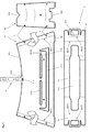
- FIG. 3 punched sheet metal pieces are shown, from which first and second side walls 31, 32; the burner frame 2 and the support member 4 are formed.
- bending lines B311 are provided on the first wall element 31, along which a flange element 319 provided with openings 7, which is connected to a second wall element 32, is angled.
- rivets are used in mutually corresponding openings 7.
- the second wall element 32 is normally arched slightly outwards to make the table grill 1 aesthetically more advantageous.
- the punched-out element of the burner frame 2 has a plurality of bending lines.
- the foot pieces 22 are angled downwards.
- the tabs 221 are bent upwards, so that they are aligned approximately horizontally.
- FIG. 4 shows a particularly advantageous embodiment of the table grill 1.
- 3 air guide elements 51, 52 are aligned parallel to the burner opening 81 and within the air duct 3 with the inwardly bent flange 312 of the first side walls connected.
- the air flows 61, 62 entering through the opening slots 311 and the flames 65 emitted by the burner 8 are detected and guided uniformly.
- the air guide elements 51, 52 have different inclinations, so that the first air guide element 51 guides the air flow 61 guided by it against the second air guide element 52, which leads a resulting, largely laminar air flow 61, 62 to the outlet opening 35.
- the first air guiding element 51 is preferably about 45 ° and the second air guiding element 52 is preferably inclined upwards by about 60 °.
- elements of heat-resistant, stainless steel are suitable as spoiler elements.
- the other elements of the table grill 1 are preferably also made of metal, which is optionally coated or finished.
Abstract
Description
Die Erfindung betrifft eine auf einen Esstisch aufsetzbare Vorrichtung zum Grillieren von Speisen nach dem Oberbegriff des Patentanspruchs 1.The invention relates to an attachable to a dining table device for grilling food according to the preamble of
Eine gattungsgemässe Vorrichtung ist aus [1],
In [1] wurde bereits beschrieben, dass das Grillieren von Fleisch über einer offenen Flamme mit Schwierigkeiten verbunden sein kann. Bei der Verwendung grösserer, typischerweise im Garten verwendeter Grillgeräte, wie sie z.B. aus [2],
Während bei einem solchen Gartengrill allfällige Mängel des Grillvorgangs, durch passende Einstellung des Grills, durch geeignete Zugabe von Holzkohle, durch Positionieren und Wenden des Grillguts, gegebenenfalls auch durch Entfernen zu stark grillierter Teile, vermieden oder beseitigt werden können, sind entsprechende Eingriffe bei einem Tischgrill nur beschränkt möglich und weitgehend unerwünscht. Der Tischgrill, der in Gaststätten oder zuhause auf dem Esstisch verwendet wird, soll optional funktionieren, ohne dass Einstellungen während des Grillvorgangs notwendig sind.While with such a garden grill any defects of the grill process, by appropriate adjustment of the grill, by suitable addition of charcoal, by positioning and turning Grillguts, possibly also by removing too much grilled parts, can be avoided or eliminated, appropriate intervention in a table grill only limited possible and largely undesirable. The table grill, which is used in restaurants or at home on the dining table, should operate optionally, without adjustments during the grilling process are necessary.
Besonders wichtig für den optimalen Verlauf des Grillprozesses ist, dass die von der Vorrichtung abgegebenen Flammen das Grillgut gleichmässig erfassen. Diesbezüglich bestehen bei bekannten Vorrichtungen, beispielsweise bei der aus [1] bekannten Lösung noch erhebliche Mängel, die den Einsatz solcher Vorrichtungen insbesondere in Gaststätten in Frage stellen. Als besonders störend wurde festgestellt, dass sich die vom Brenner abgegebenen Flammen im Wesentlichen in der Mitte konzentrieren. Die auf dem Spiess angeordneten Fleischstücke werden daher unterschiedlich durchgebraten. Während die an den Spiessenden angeordneten Fleischstücke oft ungenügend gegart werden, werden in der Mitte des Spiesses zu starke Einwirkungen auf das Grillgut registriert. Indem die Fleischstücke vom Spiess entnommen und entsprechend dem Garzustand wieder aufgesetzt werden, kann ein gleichmässigeres Garen des Grillguts erzielt werden. Diese Manipulationen, die der Tätigkeit des Grilleurs bei einer grösseren Grillanlage entsprechend, sind bei einem Tischgrill, insbesondere bei der Verwendung jedoch unerwünscht. Insbesondere in Restaurants sollen Manipulationen dieser Art vermieden werden.Particularly important for the optimal course of the grilling process is that the flames emitted by the device grasp the food evenly. In this regard, exist in known devices, for example in the known from [1] solution still significant deficiencies that make the use of such devices, especially in restaurants in question. It was found particularly annoying that the flames emitted by the burner concentrate essentially in the middle. The pieces of meat arranged on the skewer are therefore roasted through differently. While the pieces of meat arranged at the ends of the spits are often cooked insufficiently, too strong effects on the grilled food are recorded in the middle of the skewer. By the pieces of meat are removed from the skewer and put back in accordance with the state of cooking, a more even cooking of the food can be achieved. These manipulations, which correspond to the activity of the griller in a larger grill, are undesirable in a table grill, especially in use. Especially in restaurants manipulations of this kind should be avoided.
Der vorliegenden Erfindung liegt daher die Aufgabe zugrunde, einen verbesserten Tischgrill zu schaffen.The present invention is therefore an object of the invention to provide an improved table grill.
Insbesondere ist ein in Gaststätten verwendbarer Tischgrill zu schaffen, bei dem das Grillgut optimal gebraten wird, ohne dass unerwünschte Manipulationen seitens der Gäste notwendig sind.In particular, a table grill to be used in restaurants is to be created, in which the food to be grilled is optimally fried, without undesirable manipulations on the part of the guests being necessary.
Insbesondere ist ein Tischgrill zu schaffen, mittels dessen das Grillgut gleichmässiger gegart werden kann.In particular, a table grill is to create, by means of which the food can be cooked evenly.
Diese Aufgabe wird mit einem Tischgrill gelöst, welcher die in Anspruch 1 angegebenen Merkmale aufweist. Vorteilhafte Ausgestaltungen der Erfindung sind in weiteren Ansprüchen angegeben.This object is achieved with a table grill, which has the features specified in
Der mit wenigstens einem Grillgutträger, beispielsweise einem Fleischspiess, versehene Tischgrill, dient dem Grillieren von Speisen auf einem Esstisch in Gaststätten oder zuhause. Der Tischgrill weist einen mit einer Austrittsöffnung versehenen Luftschacht auf, der aus zwei einander gegenüberliegenden längeren ersten Seitenwänden und zwei einander gegenüberliegenden kürzeren zweiten Seitenwänden besteht. Innerhalb des Luftschachts ist ein Brenner mit einer längsgestreckten, vorzugsweise zumindest annähernd rechteckförmigen Brenneröffnung vorgesehen, die entsprechend der Austrittsöffnung des Luftschachts ausgerichtet ist. Erfindungsgemässe sind die einander gegenüberliegenden, ersten Seitenwände mit parallel zur Brenneröffnung ausgerichteten Öffnungsschlitzen versehen, durch die Luftströme in den Luftschacht eintreten und durch die Austrittsöffnung wieder austreten können.The provided with at least one Grillgutträger, such as a meat skewer, table grill, is used to grill food on a dining table in restaurants or at home. The table grill has an outlet opening with an air duct, which consists of two opposite longer first side walls and two opposite shorter second side walls. Within the air shaft, a burner is provided with an elongated, preferably at least approximately rectangular burner opening, which is aligned according to the outlet opening of the air shaft. According to the invention, the oppositely disposed first side walls are provided with opening slots oriented parallel to the burner opening, through which air streams can enter the air shaft and exit through the outlet opening.
Durch die Anordnung der Öffnungsschlitze in den längeren ersten Seitenwänden, vorzugsweise entsprechend der Länge des Brenners, resultiert ein ausserordentlich günstiger Verlauf der Luftströmungen im Luftschacht. Die in die Öffnungsschlitze eintretende Luft strömt praktisch vertikal nach oben, so dass bei der Austrittsöffnung des Luftschachts ein etwa rechteckiger Strömungsquerschnitt mit zumindest annähernd homogener Strömungsdichte resultiert. Die vom Brenner abgegebene Wärme wird daher gleichmässig an das Grillgut abgegeben.The arrangement of the opening slots in the longer first side walls, preferably corresponding to the length of the burner, results in an extraordinarily favorable course of the air flows in the air shaft. The air entering the opening slits flows virtually vertically upward, so that at the outlet opening of the air duct an approximately rectangular flow cross-section with at least approximately homogeneous flow density results. The heat emitted by the burner is therefore delivered evenly to the food to be grilled.
Zur Optimierung der Luftströmung werden innerhalb des Luftschachts vorzugsweise plattenförmige Luftleitelemente parallel zu den Öffnungsschlitzen angeordnet, durch die die Luftströme erfasst und zur Austrittsöffnung hin geführt werden. Auf diese Weise gelingt es, die Luftströme noch besser zu kontrollieren und auf das Grillgut zu konzentrieren.In order to optimize the air flow, plate-shaped air guide elements are preferably arranged parallel to the opening slots within the air shaft, through which the air flows are detected and guided to the outlet opening. In this way, it is possible to control the air flows even better and to concentrate on the food to be grilled.
In einer besonders vorteilhaften Ausgestaltung weisen die Luftleitelemente unterschiedliche Neigungen auf, so dass das erste Luftleitelement den von ihm geführten Luftstrom gegen das zweite Luftleitelement führt, welches einen resultierenden Luftstrom zur Austrittsöffnung hin führt. Auf diese Weise wird im Bereich der Austrittsöffnung eine laminare Luftströmung erzielt, welche eine gleichmässige Wärmeeinwirkung auf das Grillgut gewährleistet.In a particularly advantageous embodiment, the air guide elements have different inclinations, so that the first air guide element guides the air flow guided by it against the second air guide element, which leads to a resulting air flow to the outlet opening. In this way, a laminar air flow is achieved in the region of the outlet opening, which ensures a uniform heat effect on the food to be grilled.
In einer vorzugsweisen Ausgestaltung sind zumindest annähernd rechteckförmige Flanschelemente aus den ersten Seitenwänden derart ausgeschnitten, dass deren kürzere Seiten und die längere untere Kante frei liegen. Die je mit einem der Luftleitelemente versehenen Flanschelemente können daher nach innen gegeneinander gebogen werden, so dass die Öffnungsschlitze freigelegt werden.In a preferred embodiment, at least approximately rectangular flange elements are cut out of the first side walls in such a way that their shorter sides and the longer lower edge are exposed. The each provided with one of the air guide elements flange can therefore be bent inwardly against each other, so that the opening slots are exposed.
Sofern die Flanschelemente nicht selbst die Luftleitelemente bilden, können die Flanschelemente als Trägerelemente für separat gefertigte Luftleitelemente dienen. Beispielsweise werden Luftleitelemente aus wärmeresistentem Metall, vorzugsweise aus hochwertigem Stahlblech, gefertigt. Beispielsweise werden rechteckförmige Stahlbleche gestanzt, welche derart abgewinkelt werden, das Luftleitelemente und Flanschstücke resultieren, von denen Letztere, beispielsweise durch Nieten oder Toxen, mit den Flanschelementen der ersten Seitenwände verbindbar sind.If the flange elements do not themselves form the air guide elements, the flange elements can serve as carrier elements for separately manufactured air guide elements. For example, air guide elements made of heat-resistant metal, preferably made of high quality steel sheet. For example, rectangular steel sheets are punched, which are angled so that the air guide elements and flange pieces result, of which the latter, for example, by rivets or Toxen, are connectable to the flange elements of the first side walls.
Die Länge der Öffnungsschlitze entspricht vorzugsweise etwa der Länge des Brenners oder ist etwas länger gewählt, so dass der Strömungsverlauf über den gesamten Brennerbereich gleichmässig verteilt ist.The length of the opening slots preferably corresponds approximately to the length of the burner or is chosen slightly longer, so that the flow pattern is evenly distributed over the entire burner area.
In vorzugsweisen Ausgestaltungen können die Öffnungsschlitze mittels eines Schiebers zumindest teilweise verschliessbar sein, um den Garprozess zu kontrollieren und die Wärmeabgabe an das Grillgut anzupassen. Sofern beispielsweise Gemüse oder Fisch gegrillt wird, wird der Querschnitt der Öffnungsschlitze vorzugsweise reduziert. Vorzugsweise wird ein vertikal verschiebbarer Schieber vorgesehen, durch den die Höhe der Öffnungsschlitze, nicht aber deren Länge verändert wird.In preferred embodiments, the opening slots can be closed by means of a slider at least partially to control the cooking process and adjust the heat output to the food to be grilled. For example, if grilled vegetables or fish, the cross section of the opening slots is preferably reduced. Preferably, a vertically displaceable slide is provided by the height of the opening slots, but not their length is changed.
Die zweiten Seitenwände sind an deren Oberseiten vorzugsweise mit wenigstens einer der Lagerung eines Grillgutträgers dienenden Ausnehmung versehen. Auf diese Weise kann beispielsweise ein einzelner Fleischspiess in den Ausnehmungen gelagert werden.The second side walls are preferably provided on the upper sides thereof with at least one recess which serves to support a grillware carrier. In this way, for example, a single meat skewer can be stored in the recesses.
In einer weiteren vorzugsweisen Ausgestaltung sind die ersten Seitenwände, in der Oberseitenmitte durch ein Trägerelement miteinander verbunden, welches dem Halten der Enden von mehreren Grillgutträgern dient, welche in den Ausnehmungen gelagert sind. Anstelle eines einzigen Fleischspiesses können daher zwei oder mehrere Fleischspiesse von halber Länge auf den Tischgrill aufgesetzt werden.In a further preferred embodiment, the first side walls, in the top center by a support member connected to each other, which serves to hold the ends of several Grillgutträgern, which are mounted in the recesses. Instead of a single skewer of meat, two or more meat skewers of half length can therefore be placed on the table grill.
Der Brenner wird vorzugsweise in einem Brennergestell gehalten, welches ein dem Halten oder der Aufnahme des Brenners dienendes Mittelstück und zwei beidseits daran vorgesehene Fussstücke aufweist. Auf diese Weise können einfach ausgestaltete Brenner kostengünstig gefertigt und in das Brennergestell eingesetzt werden. Beispielsweise werden längsgestreckte, mit einer Folie verschlossene Aluminiumbecher verwendet, innerhalb derer eine brennbare Substanz vorzugsweise hoher Viskosität gelagert ist.The burner is preferably held in a burner frame, which has a middle piece serving to hold or receive the burner and two foot pieces provided on both sides. In this way, simply designed burner can be manufactured inexpensively and used in the burner frame. For example, elongated foil-sealed aluminum cups are used, within which a combustible substance of preferably high viscosity is stored.
Vorzugsweise ist wenigstens eines der Fussstücke des Brennergestells mit einer Lasche versehen, die der Aufnahme einer an der Unterseite der zugehörigen zweiten Seitenwand vorgesehenen Nase dient. Das Brennergestell und der Luftschacht sind daher miteinander koppelbar, was auch mittels anderer Massnahmen möglich ist. Die gewählte Lösung ist jedoch deshalb besonders vorteilhaft, weil die Kopplung resultiert, sobald der Luftschacht über das Brennergestell aufgesetzt wird. Vorzugsweise liegen beide, das Brennergestell und der damit gekoppelte Luftschacht, auf der Oberfläche des Tischs auf und sind dadurch stabil gehalten. Bei einer aufwändigeren Ausgestaltung des Brennergestells kam dieses den Luftschacht alleine tragen.Preferably, at least one of the foot pieces of the burner frame is provided with a tab which serves to receive a nose provided on the underside of the associated second side wall. The burner frame and the air shaft are therefore coupled to each other, which is also possible by other means. However, the chosen solution is particularly advantageous because the coupling results when the air duct is placed over the burner frame. Preferably, both, the burner frame and the air duct coupled thereto, lie on the surface of the table and are thereby kept stable. In a more complex design of the burner frame came this carry the duct alone.
Der erfindungsgemässe Tischgrill kann vorteilhaft aus wenigen Elementen gefertigt werden. Die beiden vorzugsweise identischen ersten und die beiden vorzugsweise identischen zweiten Seitenwände und/oder das Brennergestell werden vorzugsweise je aus einem Blechstück ausgeschnitten und geformt sind. Die ersten und zweiten Seitenwände sowie gegebenenfalls daran vorgesehene Flanschelemente werden vorzugsweise mit Öffnungen versehen, die der Aufnahme von Verbindungsmitteln dienen.The inventive table grill can be advantageously made of a few elements. The two preferably identical first and the two preferably identical second side walls and / or the burner frame are preferably each cut and formed from a piece of sheet metal. The first and second side walls and optionally provided thereon flange elements are preferably provided with openings which serve to receive connection means.
Nachfolgend wird die Erfindung anhand von Zeichnungen näher erläutert. Dabei zeigt:
- Fig. 1
- von der Seite einen
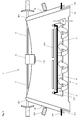
erfindungsgemässen Tischgrill 1 mit einemBrennergestell 2, über das einLuftschacht 3 aufgesetzt ist, welcher gleichzeitig als Halterung für zweiGrillgutträger 9 dient; - Fig. 2
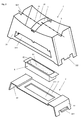
- in räumlicher Darstellung die wesentlichen Elemente des Tischgrills 1 von
Figur 1 - Fig. 3
- gestanzte Bleche, die der Fertigung des Tischgrills 1 von
Figur 1 - Fig. 4
- einen Schnitt durch
den Tischgrill 1von Figur 1 .
- Fig. 1
- from the side of an
inventive table grill 1 with aburner frame 2, via which anair duct 3 is placed, which also serves as a holder for twoGrillgutträger 9; - Fig. 2
- in spatial representation the essential elements of the
table grill 1 ofFIG. 1 ; - Fig. 3
- stamped sheets, the production of the
table grill 1 ofFIG. 1 serve; and - Fig. 4
- a section through the
table grill 1 ofFIG. 1 ,
Das aus einem Blech (siehe
Der Luftschacht 3 weist zwei einander gegenüberliegende längere erste Seitenwände 31 und zwei einander gegenüberliegende kürzere zweite Seitenwände 32 auf, deren seitliche Enden miteinander verbunden sind und die ein rechteckförmiges, sich nach oben gegen die Austrittsöffnung 35 hin verjüngendes Rohrelement bilden.
Die einander gegenüber liegenden ersten Seitenwände 31 sind mit Öffnungsschlitzen 311 versehen, die parallel zur Brenneröffnung 81 ausgerichtet sind und sich entlang dem Brenner 8 erstrecken und diesen beidseits sogar überragen. Über den gesamten Querschnitt der Öffnungsschlitze 311 kann ein gleichmässig verteilter Luftstrom 61 in den Luftschacht 3 eintreten und nach zumindest annähernd vertikalem Verlauf nach oben durch die Austrittsöffnung 35 wieder austreten. Dadurch wird gewährleistet, dass der Luftstrom 61 die vom Brenner 8 abgegebene Wärme gleichmässig gegen den oder die Grillgutträger 9 führt. Das auf die Grillgutträger 9 aufgesetzte Grillgut wird daher gleichmässig erwärmt und gegart.The opposing
In
Vorzugsweise wird der Öffnungsschlitz 311 in der ersten Seitenwand 31 vorgesehen, indem, wie in
Wie in
Die zweiten Seitenwände 32 sind ferner mit Haltegriffen 323 versehen, welche es erlauben, den Luftschacht 3 anzuheben.The
In
Das zweite Wandelement 32 wird normalerweise etwas nach aussen gewölbt, um den Tischgrill 1 ästhetisch weiter vorteilhaft auszugestalten.The
Das ausgestanzte Element des Brennergestells 2 weist mehrere Biegelinien auf. Entlang den Biegelinien B211 werden die Fussstücke 22 nach unten abgewinkelt. Entlang den Biegelinien B212 werden die Laschen 221 nach oben gebogen, so dass sie etwa waagerecht ausgerichtet sind.The punched-out element of the
Die Luftleitelemente 51, 52 weisen in dieser besonders vorteilhaften Ausgestaltung unterschiedliche Neigungen auf, so dass das erste Luftleitelement 51 den von ihm geführten Luftstrom 61 gegen das zweite Luftleitelement 52 führt, welches einen resultierenden, weitgehend laminaren Luftstrom 61, 62 zur Austrittsöffnung 35 hin führt. Das erste Luftleitelement 51 ist vorzugsweise um etwa 45° und das zweite Luftleitelement 52 ist vorzugsweise um etwa 60° nach oben geneigt. Als Luftleitelemente eignen sich insbesondere Elemente aus wärmeresistentem, rostfreiem Stahl.In this particularly advantageous embodiment, the
Die weiteren Elemente des Tischgrills 1 bestehen vorzugsweise ebenfalls aus Metall, das gegebenenfalls beschichtet bzw. veredelt ist.The other elements of the
- [1][1]
-
EP 0 617 908 A1 EP 0 617 908 A1 - [2][2]
-
DE 19649462 A1DE 19649462 A1
Claims (10)
Priority Applications (1)
| Application Number | Priority Date | Filing Date | Title |
|---|---|---|---|
| EP08151758A EP2092865A1 (en) | 2008-02-21 | 2008-02-21 | Portable grill |
Applications Claiming Priority (1)
| Application Number | Priority Date | Filing Date | Title |
|---|---|---|---|
| EP08151758A EP2092865A1 (en) | 2008-02-21 | 2008-02-21 | Portable grill |
Publications (1)
| Publication Number | Publication Date |
|---|---|
| EP2092865A1 true EP2092865A1 (en) | 2009-08-26 |
Family
ID=39535723
Family Applications (1)
| Application Number | Title | Priority Date | Filing Date |
|---|---|---|---|
| EP08151758A Withdrawn EP2092865A1 (en) | 2008-02-21 | 2008-02-21 | Portable grill |
Country Status (1)
| Country | Link |
|---|---|
| EP (1) | EP2092865A1 (en) |
Cited By (1)
| Publication number | Priority date | Publication date | Assignee | Title |
|---|---|---|---|---|
| FR2970165A1 (en) * | 2011-01-07 | 2012-07-13 | Ndc Foundry | Household cooking appliance for e.g. use in building to cook meat, has shroud made of metal sheet whose holes have determined diameter to allow passage of air toward interior of chamber and block passage of flames toward exterior of chamber |
Citations (5)
| Publication number | Priority date | Publication date | Assignee | Title |
|---|---|---|---|---|
| EP0617908A1 (en) | 1993-03-29 | 1994-10-05 | Roger Grunder | Countertop barbecue |
| DE19515080A1 (en) * | 1995-04-28 | 1996-10-31 | Buetow Klaus Dieter | Grill that is fired by charcoal |
| US5638743A (en) * | 1996-08-23 | 1997-06-17 | Wan Yeh Enterprise Co., Ltd. | Charcoal barbecue |
| WO1997042865A1 (en) * | 1996-05-17 | 1997-11-20 | Kaufman Kenneth L | Collapsible, portable combination chafing dish and barbecue |
| DE19649462A1 (en) | 1996-11-29 | 1998-06-04 | Hohmann Herstellungs Und Vertr | Garden barbecue grill |
-
2008
- 2008-02-21 EP EP08151758A patent/EP2092865A1/en not_active Withdrawn
Patent Citations (5)
| Publication number | Priority date | Publication date | Assignee | Title |
|---|---|---|---|---|
| EP0617908A1 (en) | 1993-03-29 | 1994-10-05 | Roger Grunder | Countertop barbecue |
| DE19515080A1 (en) * | 1995-04-28 | 1996-10-31 | Buetow Klaus Dieter | Grill that is fired by charcoal |
| WO1997042865A1 (en) * | 1996-05-17 | 1997-11-20 | Kaufman Kenneth L | Collapsible, portable combination chafing dish and barbecue |
| US5638743A (en) * | 1996-08-23 | 1997-06-17 | Wan Yeh Enterprise Co., Ltd. | Charcoal barbecue |
| DE19649462A1 (en) | 1996-11-29 | 1998-06-04 | Hohmann Herstellungs Und Vertr | Garden barbecue grill |
Cited By (1)
| Publication number | Priority date | Publication date | Assignee | Title |
|---|---|---|---|---|
| FR2970165A1 (en) * | 2011-01-07 | 2012-07-13 | Ndc Foundry | Household cooking appliance for e.g. use in building to cook meat, has shroud made of metal sheet whose holes have determined diameter to allow passage of air toward interior of chamber and block passage of flames toward exterior of chamber |
Similar Documents
| Publication | Publication Date | Title |
|---|---|---|
| EP2866623B1 (en) | Grill | |
| DE3026169A1 (en) | GARDEN BARBECUE GRILL | |
| CH683887A5 (en) | Horizontally and vertically movable grid. | |
| DE2746508A1 (en) | PAN AND COOKER COMBINATION KIT | |
| EP2092865A1 (en) | Portable grill | |
| EP2241232B1 (en) | Grill | |
| DE102011120756B4 (en) | grill | |
| EP2615380B1 (en) | Cooking chamber insert | |
| DE19935983A1 (en) | Cooker has food carrier that can be pivoted so carrier floor is inclined in at least one position and any liquid on it can flow to peripheral edge of carrier floor | |
| DE102017220645A1 (en) | grill | |
| DE2602716C2 (en) | Electrically heated household appliance | |
| DE3824413A1 (en) | Device for the heat treatment of foodstuffs | |
| EP3900584B1 (en) | Barbecue | |
| DE10200365C1 (en) | Cooking appliance for fast food stall, especially for potato waffles, has hinged plates in frying pan to take food portions and turn them over | |
| DE3533558C2 (en) | ||
| DE102015006247A1 (en) | Grill and grill for a barbecue | |
| DE19717316C2 (en) | Grill device | |
| EP3990833B1 (en) | Device for extracting vapours, and method for extracting vapours by means of the device, and use of the device to extract vapours | |
| CH624003A5 (en) | Device for preparing meals under the effect of heat | |
| DE60315755T2 (en) | Improved bread sled for toasters | |
| DE2917071A1 (en) | Electric barbecue grill with height adjustable heating rods - which are formed as removable units together with switch controls | |
| DE102022208147A1 (en) | Cooking system with extractor hood | |
| DE19907053A1 (en) | Grill has an adjustable cooked food support that can be removed from the base structure | |
| DE102010028505A1 (en) | Surface pot carrier for gas hob, particularly gas cooktop or cookware, has pot carrier frame and lamellas arranged within pot carrier frame, where lamella edges forms bearing surface for cooking product container | |
| DE2734332C3 (en) | Gas-heated grill device |
Legal Events
| Date | Code | Title | Description |
|---|---|---|---|
| PUAI | Public reference made under article 153(3) epc to a published international application that has entered the european phase |
Free format text: ORIGINAL CODE: 0009012 |
|
| AK | Designated contracting states |
Kind code of ref document: A1 Designated state(s): AT BE BG CH CY CZ DE DK EE ES FI FR GB GR HR HU IE IS IT LI LT LU LV MC MT NL NO PL PT RO SE SI SK TR |
|
| AX | Request for extension of the european patent |
Extension state: AL BA MK RS |
|
| AKX | Designation fees paid | ||
| REG | Reference to a national code |
Ref country code: DE Ref legal event code: 8566 |
|
| STAA | Information on the status of an ep patent application or granted ep patent |
Free format text: STATUS: THE APPLICATION IS DEEMED TO BE WITHDRAWN |
|
| 18D | Application deemed to be withdrawn |
Effective date: 20100227 |