EP2091683B1 - Pressure beam for a sawing machine - Google Patents
Pressure beam for a sawing machine Download PDFInfo
- Publication number
- EP2091683B1 EP2091683B1 EP07801798A EP07801798A EP2091683B1 EP 2091683 B1 EP2091683 B1 EP 2091683B1 EP 07801798 A EP07801798 A EP 07801798A EP 07801798 A EP07801798 A EP 07801798A EP 2091683 B1 EP2091683 B1 EP 2091683B1
- Authority
- EP
- European Patent Office
- Prior art keywords
- pressure beam
- suction extraction
- suction
- sawing
- chamber
- Prior art date
- Legal status (The legal status is an assumption and is not a legal conclusion. Google has not performed a legal analysis and makes no representation as to the accuracy of the status listed.)
- Not-in-force
Links
Images


Classifications
-
- B—PERFORMING OPERATIONS; TRANSPORTING
- B23—MACHINE TOOLS; METAL-WORKING NOT OTHERWISE PROVIDED FOR
- B23D—PLANING; SLOTTING; SHEARING; BROACHING; SAWING; FILING; SCRAPING; LIKE OPERATIONS FOR WORKING METAL BY REMOVING MATERIAL, NOT OTHERWISE PROVIDED FOR
- B23D47/00—Sawing machines or sawing devices working with circular saw blades, characterised only by constructional features of particular parts
- B23D47/04—Sawing machines or sawing devices working with circular saw blades, characterised only by constructional features of particular parts of devices for feeding, positioning, clamping, or rotating work
-
- B—PERFORMING OPERATIONS; TRANSPORTING
- B23—MACHINE TOOLS; METAL-WORKING NOT OTHERWISE PROVIDED FOR
- B23D—PLANING; SLOTTING; SHEARING; BROACHING; SAWING; FILING; SCRAPING; LIKE OPERATIONS FOR WORKING METAL BY REMOVING MATERIAL, NOT OTHERWISE PROVIDED FOR
- B23D59/00—Accessories specially designed for sawing machines or sawing devices
- B23D59/006—Accessories specially designed for sawing machines or sawing devices for removing or collecting chips
Definitions
- the invention relates to a pressure beam for a sawing machine according to the preamble of claim 1.
- Such a pressure bar is off DE 4 433 829 A1 known.
- Sawing machines for example panel dividing systems, usually have a support table on which the plate-shaped workpieces are fed to a saw. The saw blade is moved along a slot in the support table. To increase the precision of the saw cut the workpiece is pressed in the area of the saw by a pressure bar on the support table. So that the movement of the saw blade is not disturbed by the pressure bar, there is a cutting gap in the underside of the pressure bar, in which the saw blade engages during its movement.
- a suction channel is arranged above the cutting gap in the pressure bar, which can be connected by means of a suction to a suction source.
- a suction channel which, however, is arranged predominantly laterally from the kerf.
- Object of the present invention is to provide a pressure bar of the type mentioned in the deposits as possible reliably prevents saw dust in the pressure bar or these are at least reduced.
- the pressure bar according to the invention has the advantage that the suction power over the length of the pressure bar across is significantly more uniform than in the conventional pressure bar. In this way it can be prevented that there are areas in which the suction power is not sufficient to dissipate the sawdust in a required and desired manner from the sawing room. An undesirable accumulation of sawdust in the sawing room or in other components of the pressure bar is thus avoided.
- the suction channel extends over the entire length of the sawing space, and correspondingly, the fluid connection is also present over the entire length of the suction channel and the sawing space.
- the resulting chips are sucked on the shortest route directly from the sawing room. This leads to a better extraction result, since the chips do not have to be transported along to the sawing space over its entire length and thereby settle again.
- a suction duct arranged directly above the sawing space has a high degree of efficiency, since the number or extent of the changes in direction of the saw dust from the workpiece to the suction duct is reduced or even no changes in direction are required at all.
- a partition whose edge defines a gap associated with the fluid connection can be formed by such a sheet metal part. This also reduces the design effort.
- suction power and / or to even out the suction power over the length of the pressure bar contributes when a plurality of separate and successively arranged suction channels is provided, which each have their own suction and a separate fluid connection to the sawing room out.
- Each of these fluid connections then again has a cross-section which is larger near the suction opening and a smaller cross-section from the suction opening.
- the extraction channels can be switched on and off individually and / or the corresponding fluid connections can be selectively changed. As a result, the amount of exhaust air can be reduced, which in turn reduces the energy consumption during operation.
- the suction power can be partially concentrated on particularly stressed areas of the sawing space, for example, when a cross-section is performed.
- the cross-section of the fluid connection may be adjustable in whole or in sections, so as to be able to adapt the suction amount individually to the needs of the current operation and / or the individual machine.
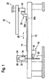
- FIG. 1 It carries a sawing machine as a whole the reference numeral 10. It comprises a horizontal support table 12, on which a workpiece 14, possibly also an entire stack of workpieces, can be stored.
- the sawing machine 10 further comprises a saw 16 with a saw carriage 18 and a Saw blade 20.
- the saw carriage 18 can be moved in a direction perpendicular to the sheet plane and perpendicular to the plane of the support table 12. In this way, the workpiece 14 can be sawn into sections.
- the sawing machine 10 In order to move the workpiece 14 to the saw 16, the sawing machine 10 also has a feed device 22. To this belongs a program pusher 24, which can be moved in the direction of the double arrow 26. At the program pusher 24 a plurality of collets 28 are mounted between the jaws 30a and 30b of the saw 16 remote edge of the workpiece 14 can be stretched.
- the saw blade 20 protrudes, as from FIG. 1 it can be seen, in the sawing of the saw carriage 18 slightly beyond the top of the support table 12 addition.
- the sawing machine 10 has a pressure bar 32. This is an elongate part perpendicular to the plane of the page FIG. 1 over the entire width of the support table 12 and thus over the entire length of the cutting line of the saw 16 extends.
- the pressure bar 32 is mounted vertically displaceably at its two ends on vertical supports. For illustration purposes is in FIG. 1 however, only the rear of the two vertical beams, which bears the reference numeral 34, is shown.
- the vertical displaceability of the pressure bar 32 is indicated by a double arrow 36, the linear guide of the pressure bar 32 in the carrier 34 is denoted by 38.
- the pressure bar 32 is lowered onto the workpiece 14, that is, the workpiece 14 is jammed between the pressure bar 32 and the support table 12.
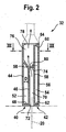
- the pressure bar is constructed in the present embodiment as a sheet metal construction. In one embodiment, not shown, it could be constructed of aluminum profiles. He includes a in FIG. 2 left housing part 40 and a right housing part 42.
- the left housing part 40 comprises an outer wall 44, which forms the inner wall of the housing part 40 in the upper region of the pressure bar 32.
- this has an inner wall 46, which is arranged at a distance D to the outer wall 44.
- outer wall 44 and inner wall 46 are interconnected by a horizontal sheet metal strip 48, at the top by an oblique sheet metal strip 50.
- the left housing 40 has a closed sheet metal box 52 with high torsional and bending stiffness.
- the right housing part 42 is constructed in the embodiment shown here as a rectangular metal box 54, with an outer wall 56, an inner wall 58 and the top and bottom connecting metal strips 60 and 62. From the left housing part 40 protrudes from the upper edge of the outer wall 44 is a horizontal to right housing part 42 extending metal strip 64 from. This is connected at its projecting end in a manner not shown with the right housing part 42. At its two end faces of the pressure bar 32 is closed by sheet metal panels 66 and 68 (see FIG. 3 ).
- FIG. 2 how out FIG. 2 it can be seen, the inner wall 46 of the left housing part 40 is spaced from the inner wall 58 of the right housing part 42. As a result, a sawing space 70 is formed between these two inner walls 46 and 58, the is open downwards or outwards via a kerf 72. In this way, during operation of the sawing machine 10, the saw blade 20 can engage in the sawing space 70, as in FIG FIG. 2 is shown by the dotted line indicated saw blade 20.
- the metal strip 50, the outer wall 44 of the left housing part 40, the metal strip 64, a portion of the inner wall 58 of the right housing part 42 and the metal strip 74 define a suction channel 76.
- the metal strip 74 forms insofar a partition between the saw chamber 70 and the suction 76th
- the suction channel 76 is connected via a suction opening 78, which is present in the metal strip 64, with a suction source, not shown.
- the suction source may be, for example, a suction pump.
- the partition wall 74 does not extend from the inner wall 58 of the right housing part 42 quite to the inner wall 46 of the left housing part 40, but ends at a distance therefrom.
- the projecting edge of the partition wall 74 limits so far a gap 80 which, as will be described in more detail below, forms a fluid connection between the saw chamber 70 and the suction channel 76 arranged directly above it.
- the projecting edge of the partition wall 74 is inclined, which causes the gap 80, starting from the suction opening 78, continuously, namely linearly expanded. Or, in other words, near the suction opening 78, the gap 80 has a smaller cross section than far away from the suction opening 78.
- the pressure bar 32 has a second suction channel 76 ', which adjoins the suction channel 76 in the longitudinal direction.
- Each of these suction channels 76 and 76 ' has its own outlet opening, wherein the outlet opening of the suction channel 76' is designated by 78 '.
- the suction channels 76 and 76 ' are separated by a partition wall 84.
- Each suction channel 76 and 76 ' has its own fluid connection formed for the suction channel 76' through the gap 80 'and bounded by the edge of a sheet metal strip 74'.
- a plurality of longitudinally successively arranged suction channels and fluid connections are present.
- the suction channels are individually switched on and off and / or the corresponding fluid connections selectively changed.
- the cross section of the fluid connection can be set in whole or in sections.
Abstract
Description
Die Erfindung betrifft einen Druckbalken für eine Sägemaschine nach dem Oberbegriff des Anspruchs 1.The invention relates to a pressure beam for a sawing machine according to the preamble of claim 1.
Ein solcher Druckbalken ist aus
Bei einem aus der
Aufgabe der vorliegenden Erfindung ist es, einen Druckbalken der eingangs genannten Art zu schaffen, bei dem möglichst zuverlässig Ablagerungen von Sägestaub im Druckbalken verhindert oder diese zumindest reduziert werden.Object of the present invention is to provide a pressure bar of the type mentioned in the deposits as possible reliably prevents saw dust in the pressure bar or these are at least reduced.
Diese Aufgabe wird durch einen Druckbalken mit den Merkmalen des Anspruchs 1 gelöst. Vorteilhafte Weiterbildungen der Erfindung sind in Unteransprüchen angegeben. Darüber hinaus sind wichtige Merkmale der Erfindung in der nachfolgenden Beschreibung genannt und in der Zeichnung dargestellt. Grundsätzlich gilt, dass die besagten Merkmale für die Erfindung auch in ganz unterschiedlichen Kombinationen wichtig sein können, ohne dass hierauf jeweils explizit hingewiesen wird.This object is achieved by a pressure bar having the features of claim 1. Advantageous developments of the invention are specified in subclaims. In addition, important features of the invention are mentioned in the following description and illustrated in the drawing. In principle, the said features for the invention can also be important in very different combinations, without any explicit reference to this.
Der erfindungsgemäße Druckbalken hat den Vorteil, dass die Absaugleistung über die Länge des Druckbalkens hinweg deutlich gleichmäßiger ist als bei den herkömmlichen Druckbalken. Auf diese Weise kann verhindert werden, dass es Bereiche gibt, in denen die Absaugleistung nicht ausreicht, um den Sägestaub in einer erforderlichen und gewünschten Art und Weise aus dem Sägeraum abzuführen. Eine unerwünschte Ansammlung von Sägestaub im Sägeraum oder in sonstigen Komponenten des Druckbalkens wird so vermieden. Typischerweise erstreckt sich der Absaugkanal über die gesamte Länge des Sägeraums, und entsprechend ist auch über die gesamte Länge von Absaugkanal und Sägeraum die Fluidverbindung vorhanden. Damit werden die anfallenden Späne auf kürzestem Wege direkt aus dem Sägeraum abgesaugt. Dies führt zu einem besseren Absaugergebnis, da die Späne nicht längs zum Sägeraum über dessen ganze Länge transportiert werden müssen und sich dabei wieder absetzen.The pressure bar according to the invention has the advantage that the suction power over the length of the pressure bar across is significantly more uniform than in the conventional pressure bar. In this way it can be prevented that there are areas in which the suction power is not sufficient to dissipate the sawdust in a required and desired manner from the sawing room. An undesirable accumulation of sawdust in the sawing room or in other components of the pressure bar is thus avoided. Typically, the suction channel extends over the entire length of the sawing space, and correspondingly, the fluid connection is also present over the entire length of the suction channel and the sawing space. Thus, the resulting chips are sucked on the shortest route directly from the sawing room. This leads to a better extraction result, since the chips do not have to be transported along to the sawing space over its entire length and thereby settle again.
Besonders einfach kann die Fluidverbindung durch einen länglichen Spalt mit veränderlichem Querschnitt realisiert werden. Grundsätzlich denkbar sind aber auch diskrete Öffnungen, die jeweils oder gruppenweise unterschiedlichen Durchmesser beziehungsweise eine unterschiedliche Öffnungsfläche aufweisen.Particularly easy fluid connection can be realized by an elongated gap with variable cross-section. In principle, however, discrete openings are also conceivable, which in each case or in groups have different diameters or a different opening area.
Im Falle eines Spaltes sollte sich dieser, ausgehend von der Absaugöffnung, kontinuierlich, insbesondere linear erweitern. Dies ist einfach herstellbar und führt bereits zu einer guten Vergleichmäßigung der Absaugleistung über die Länge des Druckbalkens. Grundsätzlich denkbar ist aber auch eine stückweise konstante Weite des Spalts oder eine exponentiell anwachsende Weite.In the case of a gap, this, starting from the suction opening, should expand continuously, in particular linearly. This is easy to produce and already leads to a good homogenization of the suction over the length of the pressure bar. In principle, but also conceivable is a piecewise constant width of the gap or an exponentially increasing width.
Ein direkt oberhalb des Sägeraums angeordneter Absaugkanal hat einen hohen Wirkungsgrad, da die Anzahl beziehungsweise der Umfang der Richtungsänderungen des Sägestaubs vom Werkstück bis zum Absaugkanal reduziert wird oder sogar überhaupt keine Richtungsänderungen erforderlich sind.A suction duct arranged directly above the sawing space has a high degree of efficiency, since the number or extent of the changes in direction of the saw dust from the workpiece to the suction duct is reduced or even no changes in direction are required at all.
In diesem Zusammenhang besteht eine konstruktiv einfache und daher preisgünstige Lösung darin, dass der Spalt vom abragenden Rand einer Trennwand begrenzt wird, welche von einer im Wesentlichen vertikalen Begrenzungswand abragt und den Absaugkanal vom Sägeraum trennt.In this context, there is a structurally simple and therefore inexpensive solution in that the gap is limited by the projecting edge of a partition, which protrudes from a substantially vertical boundary wall and the suction channel separates from the sawing space.
Ebenfalls zur Vereinfachung der Konstruktion des Druckbalkens und auch zu seiner Gewichtsreduzierung trägt bei, wenn er eine Blechkonstruktion oder eine Konstruktion aus Aluminum-Strangprofilen umfasst. Derartige Konstruktionen sind darüber hinaus preiswert fertigbar.Also contributing to the simplification of the construction of the pressure beam and also to its weight reduction, if it includes a sheet metal construction or a construction of aluminum extruded profiles. Such constructions are also inexpensive manufacturable.
Bei einer solchen Blechkonstruktion kann eine Trennwand, deren Rand einen Spalt begrenzt, der zu der Fluidverbindung gehört, durch ein solches Blechteil gebildet werden. Dies reduziert ebenfalls den konstruktiven Aufwand.In such a sheet metal construction, a partition whose edge defines a gap associated with the fluid connection can be formed by such a sheet metal part. This also reduces the design effort.
Zur Erhöhung der Saugleistung und/oder zur Vergleichmäßigung der Saugleistung über die Länge des Druckbalkens trägt bei, wenn eine Mehrzahl von separaten und hintereinander angeordneten Absaugkanälen vorgesehen ist, welche jeweils über eine eigene Absaugöffnung und eine eigene Fluidverbindung zum Sägeraum hin verfügen. Jede dieser Fluidverbindungen weist dann wiederum einen nahe zur Absaugöffnung größeren und einen ferne von der Absaugöffnung kleineren Querschnitt auf. In Weiterbildung hierzu wird vorgeschlagen, dass die Absaugkanäle einzeln zu- und abschaltbar und/oder die entsprechenden Fluidverbindungen gezielt veränderbar sind. Hierdurch kann die Abluftmenge reduziert werden, was wiederum den Energiebedarf im betrieb reduziert. Außerdem kann so die Absaugleistung partiell auf besonders beanspruchte Bereiche des Sägeraums konzentriert werden, beispielsweise dann, wenn ein Querschnitt durchgeführt wird.To increase the suction power and / or to even out the suction power over the length of the pressure bar contributes when a plurality of separate and successively arranged suction channels is provided, which each have their own suction and a separate fluid connection to the sawing room out. Each of these fluid connections then again has a cross-section which is larger near the suction opening and a smaller cross-section from the suction opening. In a further development, it is proposed that the extraction channels can be switched on and off individually and / or the corresponding fluid connections can be selectively changed. As a result, the amount of exhaust air can be reduced, which in turn reduces the energy consumption during operation. In addition, the suction power can be partially concentrated on particularly stressed areas of the sawing space, for example, when a cross-section is performed.
Der Querschnitt der Fluidverbindung kann insgesamt oder abschnittsweise einstellbar sein, um so die Absaugmenge individuell an die Bedürfnisse des aktuellen Betriebs und/oder der individuellen Maschine anpassen zu können.The cross-section of the fluid connection may be adjustable in whole or in sections, so as to be able to adapt the suction amount individually to the needs of the current operation and / or the individual machine.
Nachfolgend wird ein besonders bevorzugtes Ausführungsbeispiel der vorliegenden Erfindung unter Bezugnahme auf die beiliegende Zeichnung näher erläutert.Hereinafter, a particularly preferred embodiment of the present invention will be explained in more detail with reference to the accompanying drawings.
In der Zeichnung zeigen:
- Figur 1
- eine schematische Seitenansicht einer Sägemaschine mit einem Druckbalken;
- Figur 2
- einen Schnitt durch den Druckbalken von
Figur 1 ; - Figur 3
- einen Schnitt längs der Linie III-III von
Figur 2 ; und - Figur 4
- eine Seitenansicht auf den Druckbalken von
Figur 1 .
- FIG. 1
- a schematic side view of a sawing machine with a pressure bar;
- FIG. 2
- a section through the pressure bar of
FIG. 1 ; - FIG. 3
- a section along the line III-III of
FIG. 2 ; and - FIG. 4
- a side view of the pressure bar of
FIG. 1 ,
In
Um das Werkstück 14 zur Säge 16 bewegen zu können, verfügt die Sägemaschine 10 auch über eine Vorschubvorrichtung 22. Zu dieser gehört ein Programmschieber 24, der in Richtung des Doppelpfeiles 26 bewegt werden kann. Am Programmschieber 24 sind mehrere Spannzangen 28 angebracht, zwischen deren Klemmbacken 30a und 30b der von der Säge 16 fern liegende Rand des Werkstücks 14 gespannt werden kann.In order to move the
Das Sägeblatt 20 ragt, wie aus
Der Druckbalken 32 ist an seinen beiden Enden an vertikalen Trägern vertikal verschieblich gelagert. Aus Darstellungsgründen ist in
Der genaue Aufbau des Druckbalkens 32 geht aus den
Wie insbesondere aus den
Das rechte Gehäuseteil 42 ist bei dem hier gezeigten Ausführungsbeispiel als rechteckiger Blechkasten 54 aufgebaut, mit einer Außenwand 56, einer Innenwand 58 sowie diese oben und unten verbindende Blechstreifen 60 und 62. Vom linken Gehäuseteil 40 ragt vom oberen Rand der Außenwand 44 ein sich horizontal zum rechten Gehäuseteil 42 erstreckender Blechstreifen 64 ab. Dieser ist an seinem abragenden Ende auf nicht näher dargestellte Art und Weise mit dem rechten Gehäuseteil 42 verbunden. An seinen beiden Stirnseiten ist der Druckbalken 32 durch Blechpaneele 66 und 68 geschlossen (vergleiche
Wie aus
Auf Höhe des oberen Randes der Innenwand 46 des linken Gehäuseteils 40 ist an der Innenwand. 58 des rechten Gehäuseteils 42 ein Blechstreifen 74 befestigt. Dieser begrenzt den Sägeraum 70 nach oben hin. Der Blechstreifen 50, die Außenwand 44 des linken Gehäuseteils 40, der Blechstreifen 64, ein Abschnitt der Innenwand 58 des rechten Gehäuseteils 42 sowie der Blechstreifen 74 begrenzen einen Absaugkanal 76. Der Blechstreifen 74 bildet insoweit eine Trennwand zwischen dem Sägeraum 70 und dem Absaugkanal 76. Der Absaugkanal 76 ist über eine Absaugöffnung 78, die im Blechstreifen 64 vorhanden ist, mit einer nicht dargestellten Saugquelle verbindbar. Bei der Saugquelle kann es sich beispielsweise um eine Saugpumpe handeln.At the height of the upper edge of the
Wie aus den
Wie aus den
In dem nicht dargestellten Ausführungsbeispiel einer Großsäge sind eine Vielzahl von in Längsrichtung hintereinander angeordneten Absaugkanälen und Fluidverbindungen vorhanden. In weiteren nicht dargestellten Ausführungsbeispielen sind die Absaugkanäle einzeln zu- und abschaltbar und/oder die entsprechenden Fluidverbindungen gezielt veränderbar. Beispielsweise kann der Querschnitt der Fluidverbindung insgesamt oder abschnittsweise einstellbar sein.In the embodiment of a large saw, not shown, a plurality of longitudinally successively arranged suction channels and fluid connections are present. In further embodiments, not shown, the suction channels are individually switched on and off and / or the corresponding fluid connections selectively changed. For example, the cross section of the fluid connection can be set in whole or in sections.
Claims (10)
- A pressure beam (32) for a sawing machine (10), having a sawing chamber (70) extending in the longitudinal direction of the pressure beam (32), which chamber is open to the outside through a cut gap (72), so that in operation, a saw blade (20) of a saw (16) can engage the sawing chamber (70), and having a suction extraction conduit (76), which is disposed parallel to the sawing chamber (70) and communicates fluidically with it; and having a suction extraction opening (78, 78'), through which the suction extraction conduit (76) can communicate with a source of suction, characterized in that the fluidic connection (80, 80') between the suction extraction conduit (76) and the sawing chamber (70) has a smaller cross section near the suction extraction opening (78, 78') than far away from the suction extraction opening (78, 78').
- The pressure beam (32) as defined by claim 1, characterized in that the fluidic connection includes an elongated gap (80, 80') extending parallel to the suction extraction conduit (76) and to the sawing chamber (70).
- The pressure beam (32) as defined by claim 2, characterized in that the gap (80, 80') widens continuously, in particular linearly, beginning at the suction extraction opening (78, 78').
- The pressure beam (32) as defined by claim 3, characterized in that the suction extraction conduit (76) is disposed directly above the sawing chamber (70).
- The pressure beam (32) as defined by claim 4, characterized in that the gap (80, 80') is bounded by the edge of a partition (74, 74') which protrudes from a substantially vertical boundary wall (58) and separates the suction extraction conduit (76) from the sawing chamber (70).
- The pressure beam (32) as defined by one of the foregoing claims, characterized in that it includes a sheet-metal construction or is constructed of aluminum profile sections.
- The pressure beam (32) as defined by claim 6, characterized in that a partition (74, 74') whose edge defines a gap (80, 80') that belongs to the fluidic connection is formed by a sheet-metal part.
- The pressure beam (32) as defined by one of the foregoing claims, characterized in that it includes a plurality of separate suction extraction conduits (76, 76'), disposed one after the other.
- The pressure beam (32) as defined by claim 8, characterized in that the suction extraction conduits (76, 76') are openable and closable individually and/or the corresponding fluidic connections (80, 80') are purposefully variable.
- The pressure beam (32) as defined by one of the foregoing claims, characterized in that the cross section of the fluidic connection (80, 80') is adjustable as a whole or in portions.
Applications Claiming Priority (2)
| Application Number | Priority Date | Filing Date | Title |
|---|---|---|---|
| DE102006055446A DE102006055446A1 (en) | 2006-11-24 | 2006-11-24 | Pressure bar for a sawing machine |
| PCT/EP2007/007365 WO2008061577A1 (en) | 2006-11-24 | 2007-08-22 | Pressure beam for a sawing machine |
Publications (2)
| Publication Number | Publication Date |
|---|---|
| EP2091683A1 EP2091683A1 (en) | 2009-08-26 |
| EP2091683B1 true EP2091683B1 (en) | 2011-11-16 |
Family
ID=38682636
Family Applications (1)
| Application Number | Title | Priority Date | Filing Date |
|---|---|---|---|
| EP07801798A Not-in-force EP2091683B1 (en) | 2006-11-24 | 2007-08-22 | Pressure beam for a sawing machine |
Country Status (4)
| Country | Link |
|---|---|
| EP (1) | EP2091683B1 (en) |
| AT (1) | ATE533582T1 (en) |
| DE (1) | DE102006055446A1 (en) |
| WO (1) | WO2008061577A1 (en) |
Cited By (1)
| Publication number | Priority date | Publication date | Assignee | Title |
|---|---|---|---|---|
| CN112222531A (en) * | 2020-10-10 | 2021-01-15 | 江西邦展建筑模板科技有限公司 | Intelligent cutting device for aluminum alloy plates |
Families Citing this family (2)
| Publication number | Priority date | Publication date | Assignee | Title |
|---|---|---|---|---|
| DE102012212391A1 (en) * | 2012-07-16 | 2014-01-16 | Frimo Group Gmbh | Retainer for retaining workpiece in processing arrangement to process workpiece by e.g. milling tool, has connection section connected with suction apparatus, so that particles developed during processing of workpiece are sucked off |
| AT521555A1 (en) | 2018-07-26 | 2020-02-15 | Fill Gmbh | Panel |
Family Cites Families (5)
| Publication number | Priority date | Publication date | Assignee | Title |
|---|---|---|---|---|
| CH96905A (en) * | 1920-03-09 | 1923-04-02 | Kuendig Arnold | Method for extracting air contaminated by solid components in at least one working machine and device for carrying out the method. |
| IT1249228B (en) * | 1991-04-10 | 1995-02-21 | Giben Impianti Spa | BILATERAL PRESSER FOR PANEL SAWS. |
| DE4331283C1 (en) * | 1993-09-15 | 1994-10-20 | Holzma Maschinenbau Gmbh | Pressure beam for panel-dividing saws |
| DE4433829C2 (en) * | 1994-09-22 | 1996-09-05 | Holzma Maschinenbau Gmbh | Pressure beams for sawing machines |
| IT1305812B1 (en) * | 1996-05-20 | 2001-05-16 | Selco S R L Ora Selco S P A | CUTTING MACHINE WITH POWDER CHIP EXTRACTION DEVICE |
-
2006
- 2006-11-24 DE DE102006055446A patent/DE102006055446A1/en not_active Ceased
-
2007
- 2007-08-22 AT AT07801798T patent/ATE533582T1/en active
- 2007-08-22 WO PCT/EP2007/007365 patent/WO2008061577A1/en active Application Filing
- 2007-08-22 EP EP07801798A patent/EP2091683B1/en not_active Not-in-force
Cited By (1)
| Publication number | Priority date | Publication date | Assignee | Title |
|---|---|---|---|---|
| CN112222531A (en) * | 2020-10-10 | 2021-01-15 | 江西邦展建筑模板科技有限公司 | Intelligent cutting device for aluminum alloy plates |
Also Published As
| Publication number | Publication date |
|---|---|
| DE102006055446A1 (en) | 2008-05-29 |
| WO2008061577A1 (en) | 2008-05-29 |
| EP2091683A1 (en) | 2009-08-26 |
| ATE533582T1 (en) | 2011-12-15 |
Similar Documents
| Publication | Publication Date | Title |
|---|---|---|
| DE102007010207B4 (en) | Panel dividing plant for dividing plate-shaped workpieces, as well as methods for their operation | |
| EP1842620B1 (en) | Cover for machine tool guides | |
| EP2917007B1 (en) | Panel sizing machine | |
| DE102009033649A1 (en) | Panel cutting device, has main saw and scoring saw devices mechanically coupled to each other, and controllable device changing horizontal distance between main saw and scoring saw independent of change in vertical position of scoring saw | |
| DE102008058162B4 (en) | sawing machine | |
| DE102008026330A1 (en) | Beamsaw | |
| DE3439739A1 (en) | WORKPIECE SUPPORT TABLE FOR PANEL SAWS | |
| EP2134519A2 (en) | Device for separating a strand of plastic material, having a carrier supporting a notching device and a cutting device | |
| EP2091683B1 (en) | Pressure beam for a sawing machine | |
| EP1636001B1 (en) | Machine for profiling oblong flat workpieces along the longitudinal edges | |
| EP2366512B1 (en) | Board separation assembly | |
| AT506146B1 (en) | sawing machine | |
| DE2740673A1 (en) | CIRCULAR SAW MACHINE FOR PLATES, PLATE PACKAGES OR DGL. | |
| DE102013206159B4 (en) | Panel sizing machine | |
| EP3081325A1 (en) | Panel cutting assembly | |
| WO2012159956A1 (en) | Format circular saw with machine housing | |
| EP2711116B1 (en) | Pressure beam for a sawing device | |
| EP2193894B1 (en) | Method for sawing up at least one board | |
| EP2022613B1 (en) | Impact device in a porous concrete cutting device | |
| EP1964797A1 (en) | Gripping device, in particular collet, for use in a feed device for plate-shaped workpieces | |
| EP1958723B1 (en) | Pressure beam for a board processing facility | |
| DE202004015554U1 (en) | splitting machine | |
| DE2921108A1 (en) | WOODWORKING MACHINE FOR TAPING AND LENGTH PROFILING FRAMEWOOD | |
| DE4433829C2 (en) | Pressure beams for sawing machines | |
| WO2019115009A1 (en) | Method for cutting elongate workpieces made of wood, plastic and the like into slats, and machine tool for carrying out such a method |
Legal Events
| Date | Code | Title | Description |
|---|---|---|---|
| PUAI | Public reference made under article 153(3) epc to a published international application that has entered the european phase |
Free format text: ORIGINAL CODE: 0009012 |
|
| 17P | Request for examination filed |
Effective date: 20090411 |
|
| AK | Designated contracting states |
Kind code of ref document: A1 Designated state(s): AT BE BG CH CY CZ DE DK EE ES FI FR GB GR HU IE IS IT LI LT LU LV MC MT NL PL PT RO SE SI SK TR |
|
| DAX | Request for extension of the european patent (deleted) | ||
| GRAP | Despatch of communication of intention to grant a patent |
Free format text: ORIGINAL CODE: EPIDOSNIGR1 |
|
| GRAS | Grant fee paid |
Free format text: ORIGINAL CODE: EPIDOSNIGR3 |
|
| GRAA | (expected) grant |
Free format text: ORIGINAL CODE: 0009210 |
|
| AK | Designated contracting states |
Kind code of ref document: B1 Designated state(s): AT BE BG CH CY CZ DE DK EE ES FI FR GB GR HU IE IS IT LI LT LU LV MC MT NL PL PT RO SE SI SK TR |
|
| REG | Reference to a national code |
Ref country code: GB Ref legal event code: FG4D Free format text: NOT ENGLISH |
|
| REG | Reference to a national code |
Ref country code: CH Ref legal event code: EP |
|
| REG | Reference to a national code |
Ref country code: IE Ref legal event code: FG4D Free format text: LANGUAGE OF EP DOCUMENT: GERMAN |
|
| REG | Reference to a national code |
Ref country code: DE Ref legal event code: R096 Ref document number: 502007008698 Country of ref document: DE Effective date: 20120126 |
|
| REG | Reference to a national code |
Ref country code: NL Ref legal event code: VDEP Effective date: 20111116 |
|
| LTIE | Lt: invalidation of european patent or patent extension |
Effective date: 20111116 |
|
| PG25 | Lapsed in a contracting state [announced via postgrant information from national office to epo] |
Ref country code: IS Free format text: LAPSE BECAUSE OF FAILURE TO SUBMIT A TRANSLATION OF THE DESCRIPTION OR TO PAY THE FEE WITHIN THE PRESCRIBED TIME-LIMIT Effective date: 20120316 Ref country code: LT Free format text: LAPSE BECAUSE OF FAILURE TO SUBMIT A TRANSLATION OF THE DESCRIPTION OR TO PAY THE FEE WITHIN THE PRESCRIBED TIME-LIMIT Effective date: 20111116 |
|
| PG25 | Lapsed in a contracting state [announced via postgrant information from national office to epo] |
Ref country code: LV Free format text: LAPSE BECAUSE OF FAILURE TO SUBMIT A TRANSLATION OF THE DESCRIPTION OR TO PAY THE FEE WITHIN THE PRESCRIBED TIME-LIMIT Effective date: 20111116 Ref country code: NL Free format text: LAPSE BECAUSE OF FAILURE TO SUBMIT A TRANSLATION OF THE DESCRIPTION OR TO PAY THE FEE WITHIN THE PRESCRIBED TIME-LIMIT Effective date: 20111116 Ref country code: PT Free format text: LAPSE BECAUSE OF FAILURE TO SUBMIT A TRANSLATION OF THE DESCRIPTION OR TO PAY THE FEE WITHIN THE PRESCRIBED TIME-LIMIT Effective date: 20120316 Ref country code: SE Free format text: LAPSE BECAUSE OF FAILURE TO SUBMIT A TRANSLATION OF THE DESCRIPTION OR TO PAY THE FEE WITHIN THE PRESCRIBED TIME-LIMIT Effective date: 20111116 Ref country code: SI Free format text: LAPSE BECAUSE OF FAILURE TO SUBMIT A TRANSLATION OF THE DESCRIPTION OR TO PAY THE FEE WITHIN THE PRESCRIBED TIME-LIMIT Effective date: 20111116 Ref country code: PL Free format text: LAPSE BECAUSE OF FAILURE TO SUBMIT A TRANSLATION OF THE DESCRIPTION OR TO PAY THE FEE WITHIN THE PRESCRIBED TIME-LIMIT Effective date: 20111116 Ref country code: GR Free format text: LAPSE BECAUSE OF FAILURE TO SUBMIT A TRANSLATION OF THE DESCRIPTION OR TO PAY THE FEE WITHIN THE PRESCRIBED TIME-LIMIT Effective date: 20120217 |
|
| REG | Reference to a national code |
Ref country code: IE Ref legal event code: FD4D |
|
| PG25 | Lapsed in a contracting state [announced via postgrant information from national office to epo] |
Ref country code: CY Free format text: LAPSE BECAUSE OF FAILURE TO SUBMIT A TRANSLATION OF THE DESCRIPTION OR TO PAY THE FEE WITHIN THE PRESCRIBED TIME-LIMIT Effective date: 20111116 |
|
| PG25 | Lapsed in a contracting state [announced via postgrant information from national office to epo] |
Ref country code: BG Free format text: LAPSE BECAUSE OF FAILURE TO SUBMIT A TRANSLATION OF THE DESCRIPTION OR TO PAY THE FEE WITHIN THE PRESCRIBED TIME-LIMIT Effective date: 20120216 Ref country code: SK Free format text: LAPSE BECAUSE OF FAILURE TO SUBMIT A TRANSLATION OF THE DESCRIPTION OR TO PAY THE FEE WITHIN THE PRESCRIBED TIME-LIMIT Effective date: 20111116 Ref country code: EE Free format text: LAPSE BECAUSE OF FAILURE TO SUBMIT A TRANSLATION OF THE DESCRIPTION OR TO PAY THE FEE WITHIN THE PRESCRIBED TIME-LIMIT Effective date: 20111116 Ref country code: DK Free format text: LAPSE BECAUSE OF FAILURE TO SUBMIT A TRANSLATION OF THE DESCRIPTION OR TO PAY THE FEE WITHIN THE PRESCRIBED TIME-LIMIT Effective date: 20111116 Ref country code: CZ Free format text: LAPSE BECAUSE OF FAILURE TO SUBMIT A TRANSLATION OF THE DESCRIPTION OR TO PAY THE FEE WITHIN THE PRESCRIBED TIME-LIMIT Effective date: 20111116 Ref country code: IE Free format text: LAPSE BECAUSE OF FAILURE TO SUBMIT A TRANSLATION OF THE DESCRIPTION OR TO PAY THE FEE WITHIN THE PRESCRIBED TIME-LIMIT Effective date: 20111116 |
|
| PG25 | Lapsed in a contracting state [announced via postgrant information from national office to epo] |
Ref country code: IT Free format text: LAPSE BECAUSE OF FAILURE TO SUBMIT A TRANSLATION OF THE DESCRIPTION OR TO PAY THE FEE WITHIN THE PRESCRIBED TIME-LIMIT Effective date: 20111116 Ref country code: RO Free format text: LAPSE BECAUSE OF FAILURE TO SUBMIT A TRANSLATION OF THE DESCRIPTION OR TO PAY THE FEE WITHIN THE PRESCRIBED TIME-LIMIT Effective date: 20111116 |
|
| PLBE | No opposition filed within time limit |
Free format text: ORIGINAL CODE: 0009261 |
|
| STAA | Information on the status of an ep patent application or granted ep patent |
Free format text: STATUS: NO OPPOSITION FILED WITHIN TIME LIMIT |
|
| 26N | No opposition filed |
Effective date: 20120817 |
|
| REG | Reference to a national code |
Ref country code: DE Ref legal event code: R097 Ref document number: 502007008698 Country of ref document: DE Effective date: 20120817 |
|
| BERE | Be: lapsed |
Owner name: HOLZMA PLATTENAUFTEILTECHNIK G.M.B.H. Effective date: 20120831 |
|
| REG | Reference to a national code |
Ref country code: CH Ref legal event code: PL |
|
| PG25 | Lapsed in a contracting state [announced via postgrant information from national office to epo] |
Ref country code: MC Free format text: LAPSE BECAUSE OF NON-PAYMENT OF DUE FEES Effective date: 20120831 |
|
| GBPC | Gb: european patent ceased through non-payment of renewal fee |
Effective date: 20120822 |
|
| PG25 | Lapsed in a contracting state [announced via postgrant information from national office to epo] |
Ref country code: CH Free format text: LAPSE BECAUSE OF NON-PAYMENT OF DUE FEES Effective date: 20120831 Ref country code: LI Free format text: LAPSE BECAUSE OF NON-PAYMENT OF DUE FEES Effective date: 20120831 Ref country code: ES Free format text: LAPSE BECAUSE OF FAILURE TO SUBMIT A TRANSLATION OF THE DESCRIPTION OR TO PAY THE FEE WITHIN THE PRESCRIBED TIME-LIMIT Effective date: 20120227 |
|
| REG | Reference to a national code |
Ref country code: FR Ref legal event code: ST Effective date: 20130430 |
|
| PG25 | Lapsed in a contracting state [announced via postgrant information from national office to epo] |
Ref country code: BE Free format text: LAPSE BECAUSE OF NON-PAYMENT OF DUE FEES Effective date: 20120831 |
|
| PG25 | Lapsed in a contracting state [announced via postgrant information from national office to epo] |
Ref country code: FI Free format text: LAPSE BECAUSE OF FAILURE TO SUBMIT A TRANSLATION OF THE DESCRIPTION OR TO PAY THE FEE WITHIN THE PRESCRIBED TIME-LIMIT Effective date: 20111116 |
|
| PG25 | Lapsed in a contracting state [announced via postgrant information from national office to epo] |
Ref country code: GB Free format text: LAPSE BECAUSE OF NON-PAYMENT OF DUE FEES Effective date: 20120822 |
|
| PG25 | Lapsed in a contracting state [announced via postgrant information from national office to epo] |
Ref country code: FR Free format text: LAPSE BECAUSE OF NON-PAYMENT OF DUE FEES Effective date: 20120831 |
|
| REG | Reference to a national code |
Ref country code: AT Ref legal event code: MM01 Ref document number: 533582 Country of ref document: AT Kind code of ref document: T Effective date: 20120831 |
|
| PG25 | Lapsed in a contracting state [announced via postgrant information from national office to epo] |
Ref country code: AT Free format text: LAPSE BECAUSE OF NON-PAYMENT OF DUE FEES Effective date: 20120831 |
|
| PG25 | Lapsed in a contracting state [announced via postgrant information from national office to epo] |
Ref country code: MT Free format text: LAPSE BECAUSE OF FAILURE TO SUBMIT A TRANSLATION OF THE DESCRIPTION OR TO PAY THE FEE WITHIN THE PRESCRIBED TIME-LIMIT Effective date: 20111116 |
|
| PG25 | Lapsed in a contracting state [announced via postgrant information from national office to epo] |
Ref country code: TR Free format text: LAPSE BECAUSE OF FAILURE TO SUBMIT A TRANSLATION OF THE DESCRIPTION OR TO PAY THE FEE WITHIN THE PRESCRIBED TIME-LIMIT Effective date: 20111116 |
|
| PG25 | Lapsed in a contracting state [announced via postgrant information from national office to epo] |
Ref country code: LU Free format text: LAPSE BECAUSE OF NON-PAYMENT OF DUE FEES Effective date: 20120822 |
|
| PG25 | Lapsed in a contracting state [announced via postgrant information from national office to epo] |
Ref country code: HU Free format text: LAPSE BECAUSE OF FAILURE TO SUBMIT A TRANSLATION OF THE DESCRIPTION OR TO PAY THE FEE WITHIN THE PRESCRIBED TIME-LIMIT Effective date: 20070822 |
|
| PGFP | Annual fee paid to national office [announced via postgrant information from national office to epo] |
Ref country code: DE Payment date: 20151019 Year of fee payment: 9 |
|
| REG | Reference to a national code |
Ref country code: DE Ref legal event code: R119 Ref document number: 502007008698 Country of ref document: DE |
|
| PG25 | Lapsed in a contracting state [announced via postgrant information from national office to epo] |
Ref country code: DE Free format text: LAPSE BECAUSE OF NON-PAYMENT OF DUE FEES Effective date: 20170301 |