EP2091443B1 - Necklift instrument - Google Patents
Necklift instrument Download PDFInfo
- Publication number
- EP2091443B1 EP2091443B1 EP07865199A EP07865199A EP2091443B1 EP 2091443 B1 EP2091443 B1 EP 2091443B1 EP 07865199 A EP07865199 A EP 07865199A EP 07865199 A EP07865199 A EP 07865199A EP 2091443 B1 EP2091443 B1 EP 2091443B1
- Authority
- EP
- European Patent Office
- Prior art keywords
- suture
- threading device
- threading
- handset
- skin
- Prior art date
- Legal status (The legal status is an assumption and is not a legal conclusion. Google has not performed a legal analysis and makes no representation as to the accuracy of the status listed.)
- Active
Links
Images


Classifications
-
- A—HUMAN NECESSITIES
- A61—MEDICAL OR VETERINARY SCIENCE; HYGIENE
- A61B—DIAGNOSIS; SURGERY; IDENTIFICATION
- A61B17/00—Surgical instruments, devices or methods
-
- A—HUMAN NECESSITIES
- A61—MEDICAL OR VETERINARY SCIENCE; HYGIENE
- A61B—DIAGNOSIS; SURGERY; IDENTIFICATION
- A61B17/00—Surgical instruments, devices or methods
- A61B17/04—Surgical instruments, devices or methods for suturing wounds; Holders or packages for needles or suture materials
- A61B17/0401—Suture anchors, buttons or pledgets, i.e. means for attaching sutures to bone, cartilage or soft tissue; Instruments for applying or removing suture anchors
-
- A—HUMAN NECESSITIES
- A61—MEDICAL OR VETERINARY SCIENCE; HYGIENE
- A61B—DIAGNOSIS; SURGERY; IDENTIFICATION
- A61B17/00—Surgical instruments, devices or methods
- A61B17/04—Surgical instruments, devices or methods for suturing wounds; Holders or packages for needles or suture materials
- A61B17/0482—Needle or suture guides
-
- A—HUMAN NECESSITIES
- A61—MEDICAL OR VETERINARY SCIENCE; HYGIENE
- A61B—DIAGNOSIS; SURGERY; IDENTIFICATION
- A61B17/00—Surgical instruments, devices or methods
- A61B17/04—Surgical instruments, devices or methods for suturing wounds; Holders or packages for needles or suture materials
- A61B17/0483—Hand-held instruments for holding sutures
-
- A—HUMAN NECESSITIES
- A61—MEDICAL OR VETERINARY SCIENCE; HYGIENE
- A61B—DIAGNOSIS; SURGERY; IDENTIFICATION
- A61B17/00—Surgical instruments, devices or methods
- A61B17/04—Surgical instruments, devices or methods for suturing wounds; Holders or packages for needles or suture materials
- A61B17/06—Needles ; Sutures; Needle-suture combinations; Holders or packages for needles or suture materials
- A61B17/06066—Needles, e.g. needle tip configurations
-
- A—HUMAN NECESSITIES
- A61—MEDICAL OR VETERINARY SCIENCE; HYGIENE
- A61B—DIAGNOSIS; SURGERY; IDENTIFICATION
- A61B17/00—Surgical instruments, devices or methods
- A61B17/04—Surgical instruments, devices or methods for suturing wounds; Holders or packages for needles or suture materials
- A61B17/06—Needles ; Sutures; Needle-suture combinations; Holders or packages for needles or suture materials
- A61B17/06166—Sutures
-
- A—HUMAN NECESSITIES
- A61—MEDICAL OR VETERINARY SCIENCE; HYGIENE
- A61B—DIAGNOSIS; SURGERY; IDENTIFICATION
- A61B17/00—Surgical instruments, devices or methods
- A61B17/04—Surgical instruments, devices or methods for suturing wounds; Holders or packages for needles or suture materials
- A61B17/0485—Devices or means, e.g. loops, for capturing the suture thread and threading it through an opening of a suturing instrument or needle eyelet
-
- A—HUMAN NECESSITIES
- A61—MEDICAL OR VETERINARY SCIENCE; HYGIENE
- A61B—DIAGNOSIS; SURGERY; IDENTIFICATION
- A61B17/00—Surgical instruments, devices or methods
- A61B17/32—Surgical cutting instruments
- A61B17/3209—Incision instruments
- A61B17/32093—Incision instruments for skin incisions
-
- A—HUMAN NECESSITIES
- A61—MEDICAL OR VETERINARY SCIENCE; HYGIENE
- A61B—DIAGNOSIS; SURGERY; IDENTIFICATION
- A61B17/00—Surgical instruments, devices or methods
- A61B2017/00743—Type of operation; Specification of treatment sites
- A61B2017/00792—Plastic surgery
-
- A—HUMAN NECESSITIES
- A61—MEDICAL OR VETERINARY SCIENCE; HYGIENE
- A61B—DIAGNOSIS; SURGERY; IDENTIFICATION
- A61B17/00—Surgical instruments, devices or methods
- A61B17/04—Surgical instruments, devices or methods for suturing wounds; Holders or packages for needles or suture materials
- A61B17/0401—Suture anchors, buttons or pledgets, i.e. means for attaching sutures to bone, cartilage or soft tissue; Instruments for applying or removing suture anchors
- A61B2017/0403—Dowels
-
- A—HUMAN NECESSITIES
- A61—MEDICAL OR VETERINARY SCIENCE; HYGIENE
- A61B—DIAGNOSIS; SURGERY; IDENTIFICATION
- A61B17/00—Surgical instruments, devices or methods
- A61B17/04—Surgical instruments, devices or methods for suturing wounds; Holders or packages for needles or suture materials
- A61B17/0401—Suture anchors, buttons or pledgets, i.e. means for attaching sutures to bone, cartilage or soft tissue; Instruments for applying or removing suture anchors
- A61B2017/0406—Pledgets
-
- A—HUMAN NECESSITIES
- A61—MEDICAL OR VETERINARY SCIENCE; HYGIENE
- A61B—DIAGNOSIS; SURGERY; IDENTIFICATION
- A61B17/00—Surgical instruments, devices or methods
- A61B17/04—Surgical instruments, devices or methods for suturing wounds; Holders or packages for needles or suture materials
- A61B17/0401—Suture anchors, buttons or pledgets, i.e. means for attaching sutures to bone, cartilage or soft tissue; Instruments for applying or removing suture anchors
- A61B2017/0409—Instruments for applying suture anchors
-
- A—HUMAN NECESSITIES
- A61—MEDICAL OR VETERINARY SCIENCE; HYGIENE
- A61B—DIAGNOSIS; SURGERY; IDENTIFICATION
- A61B17/00—Surgical instruments, devices or methods
- A61B17/04—Surgical instruments, devices or methods for suturing wounds; Holders or packages for needles or suture materials
- A61B17/0401—Suture anchors, buttons or pledgets, i.e. means for attaching sutures to bone, cartilage or soft tissue; Instruments for applying or removing suture anchors
- A61B2017/0414—Suture anchors, buttons or pledgets, i.e. means for attaching sutures to bone, cartilage or soft tissue; Instruments for applying or removing suture anchors having a suture-receiving opening, e.g. lateral opening
-
- A—HUMAN NECESSITIES
- A61—MEDICAL OR VETERINARY SCIENCE; HYGIENE
- A61B—DIAGNOSIS; SURGERY; IDENTIFICATION
- A61B17/00—Surgical instruments, devices or methods
- A61B17/04—Surgical instruments, devices or methods for suturing wounds; Holders or packages for needles or suture materials
- A61B17/0401—Suture anchors, buttons or pledgets, i.e. means for attaching sutures to bone, cartilage or soft tissue; Instruments for applying or removing suture anchors
- A61B2017/042—Suture anchors, buttons or pledgets, i.e. means for attaching sutures to bone, cartilage or soft tissue; Instruments for applying or removing suture anchors plastically deformed during insertion
- A61B2017/0422—Suture anchors, buttons or pledgets, i.e. means for attaching sutures to bone, cartilage or soft tissue; Instruments for applying or removing suture anchors plastically deformed during insertion by insertion of a separate member into the body of the anchor
- A61B2017/0425—Suture anchors, buttons or pledgets, i.e. means for attaching sutures to bone, cartilage or soft tissue; Instruments for applying or removing suture anchors plastically deformed during insertion by insertion of a separate member into the body of the anchor the anchor or the separate member comprising threads, e.g. a set screw in the anchor
-
- A—HUMAN NECESSITIES
- A61—MEDICAL OR VETERINARY SCIENCE; HYGIENE
- A61B—DIAGNOSIS; SURGERY; IDENTIFICATION
- A61B17/00—Surgical instruments, devices or methods
- A61B17/04—Surgical instruments, devices or methods for suturing wounds; Holders or packages for needles or suture materials
- A61B17/0401—Suture anchors, buttons or pledgets, i.e. means for attaching sutures to bone, cartilage or soft tissue; Instruments for applying or removing suture anchors
- A61B2017/044—Suture anchors, buttons or pledgets, i.e. means for attaching sutures to bone, cartilage or soft tissue; Instruments for applying or removing suture anchors with a threaded shaft, e.g. screws
-
- A—HUMAN NECESSITIES
- A61—MEDICAL OR VETERINARY SCIENCE; HYGIENE
- A61B—DIAGNOSIS; SURGERY; IDENTIFICATION
- A61B17/00—Surgical instruments, devices or methods
- A61B17/04—Surgical instruments, devices or methods for suturing wounds; Holders or packages for needles or suture materials
- A61B2017/0496—Surgical instruments, devices or methods for suturing wounds; Holders or packages for needles or suture materials for tensioning sutures
-
- A—HUMAN NECESSITIES
- A61—MEDICAL OR VETERINARY SCIENCE; HYGIENE
- A61B—DIAGNOSIS; SURGERY; IDENTIFICATION
- A61B90/00—Instruments, implements or accessories specially adapted for surgery or diagnosis and not covered by any of the groups A61B1/00 - A61B50/00, e.g. for luxation treatment or for protecting wound edges
- A61B90/39—Markers, e.g. radio-opaque or breast lesions markers
- A61B2090/3904—Markers, e.g. radio-opaque or breast lesions markers specially adapted for marking specified tissue
-
- A—HUMAN NECESSITIES
- A61—MEDICAL OR VETERINARY SCIENCE; HYGIENE
- A61B—DIAGNOSIS; SURGERY; IDENTIFICATION
- A61B90/00—Instruments, implements or accessories specially adapted for surgery or diagnosis and not covered by any of the groups A61B1/00 - A61B50/00, e.g. for luxation treatment or for protecting wound edges
- A61B90/39—Markers, e.g. radio-opaque or breast lesions markers
- A61B2090/3937—Visible markers
- A61B2090/395—Visible markers with marking agent for marking skin or other tissue
-
- Y—GENERAL TAGGING OF NEW TECHNOLOGICAL DEVELOPMENTS; GENERAL TAGGING OF CROSS-SECTIONAL TECHNOLOGIES SPANNING OVER SEVERAL SECTIONS OF THE IPC; TECHNICAL SUBJECTS COVERED BY FORMER USPC CROSS-REFERENCE ART COLLECTIONS [XRACs] AND DIGESTS
- Y10—TECHNICAL SUBJECTS COVERED BY FORMER USPC
- Y10S—TECHNICAL SUBJECTS COVERED BY FORMER USPC CROSS-REFERENCE ART COLLECTIONS [XRACs] AND DIGESTS
- Y10S362/00—Illumination
- Y10S362/804—Surgical or dental spotlight
-
- Y—GENERAL TAGGING OF NEW TECHNOLOGICAL DEVELOPMENTS; GENERAL TAGGING OF CROSS-SECTIONAL TECHNOLOGIES SPANNING OVER SEVERAL SECTIONS OF THE IPC; TECHNICAL SUBJECTS COVERED BY FORMER USPC CROSS-REFERENCE ART COLLECTIONS [XRACs] AND DIGESTS
- Y10—TECHNICAL SUBJECTS COVERED BY FORMER USPC
- Y10T—TECHNICAL SUBJECTS COVERED BY FORMER US CLASSIFICATION
- Y10T428/00—Stock material or miscellaneous articles
- Y10T428/24—Structurally defined web or sheet [e.g., overall dimension, etc.]
- Y10T428/24273—Structurally defined web or sheet [e.g., overall dimension, etc.] including aperture
- Y10T428/24322—Composite web or sheet
Definitions
- the present invention relates generally to devices for plastic surgery and, more particularly, to a necklift instrument for performing the procedure.
- Plastic and reconstructive surgeons have long sought to develop methods and devices to aid in the support of physical structures that have lost their natural tension and support.
- the most often treated areas include the face, the chest region, the buttocks and other regions that lose tension and sag.
- Current devices are not always adequate in providing a natural-looking structure to prevent such loss of tension in these structures.
- the aging process causes gradual and predictable changes in the soft tissue layers of the lower face and neck, the anatomical basis of which has been well documented. Loss of elasticity and fragmentation of collagen results in rhytid formation and skin redundancy. Subcutaneous fat thickens and droops or is ptotic and becomes more noticeable. Stretching of the fascia and musculature results in a loss of the supporting 'sling' of the submentum, often resulting in submandibular gland ptosis. Further loss of tone and muscular atrophy results in banding of the medial platysmal borders, blunting of the cervicomental angle and loss of lateral mandibular definition.
- Document US 2005/0203562 discloses a lighted dissector comprising an elongate shaft having a blunt dissection tip on its distal end wherein a light source emits a diffuse visible light from the blunt tip.
- the method includes the steps of providing a suture, providing a threading device comprising an elongated rod having a suture tie-off location and first and second ends, tying the suture to the suture tie-off location, inserting the first end of the elongated rod through a first opening in the patient's skin, passing the first end of the elongated rod subcutaneously to a second opening in the patient's skin, pulling the first end of the elongated rod and a portion of the suture through the second opening, without turning the elongated rod around, and passing the second end of the elongated rod subcutaneously to an opening in the patient's skin.
- the first end of the elongated rod extends out of the first opening and the second end of the elongated rod extends through the second opening.
- the first and second ends of the threading device may each be lighted at predetermined points during the method.
- the method includes the steps of placing a tape template onto a portion of a patient's skin, marking a plurality of access sites, making an opening to form a mid-line access site, performing liposuction, forming a plurality of openings in the skin at the access sites, providing a threading device having a suture secured thereto, and inserting the threading device and suture through a plurality of access sites to form a suture matrix under the skin.
- a surgical kit that includes at least two of the following at least one tape member, a lancet, a handset, a clearing device, a nose cone, a threading device, and a suture.
- the handset may include a tubular member having first and second opposite, an instrument dock extending from the first end of the tubular member that includes an opening for receiving a rod, and a light source, wherein light from the light source is directed out of the opening in the instrument dock.
- the threading device preferably includes an elongated rod having a groove defined therein that extends at least substantially circumferentially around the rod, and blunt ends.
- the threading device also preferably includes an elongated tube having first and second open ends and a suture tie-off location disposed approximately halfway between the first and second ends, and a light guide running through the elongated tube.
- the light guide has first and second ends that are substantially flush with the first and second ends of the tube.
- the tape member preferably includes a first layer that has at least two perforations defined therethrough, and a second layer overlying the first layer that has at least two perforations defined therethrough. At least one of the perforations of the second layer at least partially overlaps at least one of the perforations of the first layer.
- the clearing device preferably includes a neck and a clearing portion extending from the neck in a curved path that defines a plane that is approximately perpendicular to the longitudinal axis of the neck.
- the technique for placing a suture in a person's body is preferably used in the field of plastic surgery and involves several steps which each require specific instrumentation.
- the liposuction portion of the procedure is performed without a large incision under the chin.
- the placement of the suture support matrix is performed through several small access sites in the neck area under the jaw. The advantage is that the entire support system can be placed without the typical large incision under the chin that is necessary for the surgeon to see the operative field. In addition the surgery is less invasive and does not require an extensive dissection of the skin in the area under the chin.
- support suture(s) also referred to herein as the support structure or support matrix 200 and is shown in FIGS. 25 and 56 .
- any references to liposuction techniques herein are only exemplary.
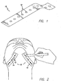
- tape 10 is a clear piece of tape with perforations 12 therethrough that are spaced apart at predetermined locations.
- Tape 10 includes adhesive thereon so that it can be secured to the patient's skin.
- tape 10 is a one inch wide clear tape with about 2 mm circular perforations 12 defined therethrough that are spaced about every 5 mm along the center of the tape.
- the perforations 12 are preferably positioned along the longitudinal center of the tape 10, however this is not a limitation on the present invention.
- tape 10 is not clear.
- tape 10 is provided in roll form. However, this is not a limitation on the present invention.
- Tape 10 is used in immediate pre-operative planning to determine the placement of access sites 14, which will determine the placement of the support matrix 200. Tape 10 is used as a guide to help provide proper placement of each suture and its corresponding pivot point (as described below). Perforations 12 are used to mark access sites 14 for the surgery.
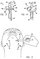
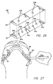
- first and second tape members 10 are placed on each side of the skin overlying the undersurface of the mandible, as is shown in FIG. 2 .
- tape 10 is utilized with the patient sitting upright, which allows the natural neck contours to be visible. This is not a limitation on the present invention, however.
- the surgeon uses tape 10 and the plurality of perforations 12 to develop a surgical approach that is individually tailored for each patient, depending on the correction desired. As those skilled in the art will appreciate, placement of the support matrix 200 will be different for different patients depending on the patient's anatomy.
- the exemplary 5 mm span between perforations 12 allows placement of pivot points in close proximity. This results in a dense support matrix allowing elevation of muscle and glandular tissue. For example, pivot points may be placed 1-2 cm apart if minimal support is needed.
- pivot points may be placed 1-2 cm apart if minimal support is needed.
- the surgeon marks skin exposed through the desired perforations 12 with a surgical marking pen or the like. These markings 14 indicate the areas that require suture placement to elevate the soft tissue of the neck.
- the markings 14 made using the first tape member 10 are symmetrical to the markings 14 made using the second tape member 10.
- each of the markings 14 define a location or access site that will be punctured to allow subcutaneous access at that location.
- the access sites, markings and punctures will all be labeled 14 herein.
- the tape 310 can be laminated.
- the laminated tape 310 preferably includes two layers 311 and 313.
- the top layer 313 has one set of holes or perforations 313a and the bottom layer 311 has two sets of perforations 311a and 311b.
- Perforations 311a and 313a in the different layers 311 and 313 are preferably concentric. However, any amount of overlap between perforations 311a and 313a is within the scope of the present invention. This arrangement of perforations helps the surgeon when marking the patient.
- the support matrix 200 is formed similar to the way a shoelace is weaved through a shoe. Therefore, in marking the skin for the access sites 14, it can be helpful to mark the skin with two different color markers, for example, red and blue (shown as solid and stippled in the figures). Then, when the matrix 200 is created or the "shoe is laced" the surgeon goes from blue marking to blue marking and red marking to red marking (which each have an access site 14 formed therein, as described below).
- the surgeon positions the laminated tape 310 as desired and marks the perforations (the concentric or double perforations 311a and 313a) with the first color. Then, the surgeon peels the first or top layer 313 off, thereby exposing the second set of perforations 311b. The surgeon then marks the second set of perforations 311b with a different color marker.
- Tape 310 can also be configured in a rolled form. In another preferred embodiment, a single piece of tape 310 can be used that extends all the way around the jaw line or other location on the body. This helps align the markings on each side.
- tape 10 or 310 is preferably used before performing liposuction or other desired procedure. However, this is not a limitation on the present invention. In another embodiment, tape can be used after liposuction is performed. In another embodiment, the tape can be omitted and the surgeon can mark or puncture the skin as desired.
- the tape 10 or 310 can be used on areas of the body other than the chin.
- the tape (and the remainder of the procedure described below) can be used for a face lift or in the MACS-lift or when placing a neck defining suture (both described below).
- the patient is ready for liposuction. It will be understood that when the surgical procedure does not include liposuction, the markings are made before whatever procedure is being performed.
- the patients head and neck are prepped and draped in a sterile fashion and local anesthetic is injected into the area under the chin. A small opening (referred to herein as the midline sub-mental access site) is made in this area.
- Tumescent fluid is injected into the entire area under the chin, including the neck region. Liposuction is performed on the entire region. Upon completion, the area is once again infiltrated with the tumescent fluid. This subcutaneous infusion results in the elevation of the skin from the platysma muscle.
- a lancet 40 is used to create access sites 14 by puncturing the dermis at the points marked using tape 10 or 310.
- lancet 40 includes a blade 42 that has two sharp edges 43 that end at a point 44 with two blunt edges 46 therebelow.
- blade 42 is about 8 mm in length.
- Blunt edges 46 of blade 42 extend from a flange or stop member 48 that prevents blade 42 from going deeper into the skin than desired. Flange 48 ensures consistent depth of blade penetration.
- blade 42 is sized to allow placement of skin ports 80 as described below.
- Stop member 48 has an upper surface 48a and a lower surface 48b.
- the blade 42 extends upwardly from the upper surface 48a of the stop member 48.
- the two sharp edges 43 each have first and second ends 43a and 43b, respectively and the two blunt edges 46 each have first and second ends 46a and 46b, respectively.
- first ends 43a of the sharp edges 43 meet at point 44 and extend downwardly from point 44 at an angle of 90° or less.
- the first ends 46a of the two blunt edges 46 extend downwardly from the second ends 43b of the two sharp edges 43.
- the sharp edges 43 and blunt edges 46 meet at an obtuse angle.
- the second ends 46b of the two blunt edges 46 are connected to the stop member 48, which, in a preferred embodiment, is disc-shaped.
- the blade 42 can extend from the stop member 48 at a non-right angle (e.g., an acute angle).
- lancet 40 includes an attachment member 50 that extends downwardly from the lower surface 48b of the stop member 48 and allows the lancet 40 to be secured on a standard scalpel handle 52.
- lancet 40 can be provided with a unitary handle.
- the access sites 14 are developed by puncturing of the skin with the percutaneous lancet 40 at the markings developed using tape 10, as shown in FIG. 5 .
- Lancet 40 allows puncturing of the skin in order to gain access to the neck region and preferably ensures that each access site is as small as possible, allowing the placement of the support system 200.
- lancet 40 creates punctures instead of incisions, which minimalizes trauma and the risk of scarring.
- incisions can be used in another embodiment.
- Handset 60 is embodied in a reusable insertion device with an instrument dock 64 at an end thereof.
- handset 60 also includes a fiber-optic light port 62.
- the handset is ergonomically designed to fit into the surgeon's hand when gripped.
- this is not a limitation on the present invention.
- handset 60 is made of a metal, such as stainless steel or titanium.
- instrument port 64 is compatible with a number of the instruments that are used in the inventive surgical procedure. The design structure and form allows right to left hand interchangability with ease and precision.
- Instrument dock 64 may include an inner threaded surface or threaded female connector 66 and a larger male connector 68 that interlocks with the skin ports 80 (described below) allowing deployment and illumination.
- the instrument dock 64 is adapted to dock with certain instruments, as will be described more fully below.
- Handset 60 will be described more fully below in conjunction with the instruments with which it is intended to be used.
- the fiberoptic light port 62 allows docking with a fiberoptic light cord (not shown). The transmission of fiberoptic light through the handset 60 illuminates each device when it is attached to the working end of instrument dock 64.
- the handset 60 may include a fiberoptic core 70, which is made up of at least one, and preferably a plurality, of fiberoptic strands.
- a fiberoptic light cord When a fiberoptic light cord is connected to light port 62, the light is transmitted through the fibers and out through an opening 72 that is coaxial with female connector 66.
- the handset 60 (and associated instruments) can be provided without a fiberoptic core.
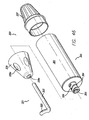
- Handset 360 may be battery operated and disposable.
- the handset includes a main body portion 359, housing 361, power source(s) 363, light source 365, instrument dock 364 and an obturator or clearing device 321 (described more fully below).
- the light source 365 is an LED light source 365a and the power source 363 includes a plurality of batteries 363 arranged in series in housing 361.
- the circuitry for providing power to the light source is well known in the art and therefore a description will be omitted.
- the handset (in particular, the housing 361) may generally be tubular. In other words, it does not have to have a circular cross-section; it may be square, oval or other shape.
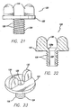
- the handset 360 may be provided with the batteries 363 therein. Something is used to break the circuit so that the batteries are not drained prior to use. For example, a thin piece of paper or the like (referred to herein as a rip cord or circuit breaker 369) can be inserted between two batteries 363 to keep the circuit open and is then removed at the appropriate time to allow electrical communication between the batteries, thereby closing the circuit and lighting the light source 365. As shown in FIG. 29 , the housing preferably has a slot 371 defined therein through which rip cord 369 extends.
- handset 360 In use, when the surgeon is ready to use the handset 360, he/she pulls the rip cord to power the LED 365a and it will then run for a predetermined amount of time (e.g., until the batteries die). It will be understood that handset 360 can also be constructed so that it is reusable. For example, those skilled in the art will understand that it can be designed to be plugged into a typical wall outlet and run on AC power.
- the power source and light source may be sealed off from the outside of the handset 360. This helps with sterilization and prevents contamination of the working area.
- a latching switch mechanism can be used for activating the batteries or turning on the light source.
- the handset 360 can include a tail cone or button 337 that can be twisted or pressed to switch the device on.
- a switch can be located inside female receiver 366. When clearing device 321, clearing device assembly 341 or threading rod 300 (described below) are inserted into the receiver 366, the switch is switched and the batteries and LED are activated.
- the ring located next to o-ring 335 in FIG. 46 could be coupled to a magnetically activated switch.
- FIGS. 8-11 show a skin port 80.
- a plurality of skin ports 80 are used.
- Skin ports 80 are disposable clear plastic sleeves that are each inserted into one of the access sites 14 created by lancet 40.
- skin port 80 includes a flange or cuff 82 that has a tube 84 that extends from it. One end of the tube or sleeve 84 is inserted into the puncture 14 in the skin until the flange 82 rests against the outer surface of the skin. The flange 82 and tube 84 cooperate to define a tunnel 86 that will provide access to the area under the skin.
- the port 80 is comprised of colored clear plastic.
- the port 80 can also be made of other materials, does not have to be clear and does not have to be colored.
- the handset 60 or 360 may be used to deploy each port 80 through the individual access sites 14.
- the skin ports 80 come in a kit, however this is not a limitation on the present invention.
- the handset 60 design allows quick interlocking with the skin port 80 to remove it from the kit. It will be understood that any design that allows the handset 60 to interlock with or engage the skin port 80 so that it can be deployed into the access site 14 is within the scope of the present invention.
- the port 80 may be snap fit onto the male connector 68.
- the male connector 68 can include a ridge 68a extending circumferentially therearound that cooperates with an indented ring 82a in the flange 82.
- the ridge 68a and indented ring 82a provide a snap fit so that the port 80 is engaged with the male connector 68 of the handset 60.
- Other snap fit arrangements are contemplated.
- the skin port 80 includes an anchor system that comprises threads 88 on the outer surface of the tube 84 and a folding mechanism 90.
- the folding mechanism 90 preferably includes a pair of folding members 90a that are attached to an internally threaded ring 90b that moves up and down the tube 84 on threads 88.
- the male connector 68 includes a plurality of teeth 68b on an end thereof that are adapted to interlock with teeth 82b on the port 80.
- teeth 68b engage or mesh with teeth 82b.
- the tube 84 is inserted through the access site 14, to deploy the folding mechanism 90, the handset 60 is turned in a clockwise direction (port 80 can be designed to deploy in a counter-clockwise direction as well). Because teeth 68b and 82b are engaged, the tube 84 turns with handset 60 and within flange 82, thereby causing the internally threaded ring 90b to move upwardly along threads 88. As can be seen in FIG.
- folding members 90a include a fold crease 90c. As threaded ring 90b moves upwardly, the folding members 90a fold, as shown in FIG. 10 , thereby providing an anchor and preventing port 80 from pulling out of access site 14.
- the folding members 90a can be disposed in an unfolded position ( FIG. 9 ) and a folded position ( Fig. 10 ).
- Flange 82 may include a plurality of spikes 94 extending downwardly therefrom that burrow into the skin and help anchor the port 80 in place.
- the handset 60 includes the fiber optic core 70 and the skin port 80 is clear, upon insertion, transcutaneous visualization of the lighted probe tip will allow safe deployment of skin port 80. Because of the anchoring system, as the handset is withdrawn, the ridge 68a pulls out of the indented ring 82a and the skin port 80 is secured in place. The surgeon can use his/her thumb to aid in separating the port 80 from the instrument dock 64.
- the ports 80 are disposable and are only used for a single surgery. It will be understood that the ports are simply used to gain access to the surgical field. Therefore, the type of port used is not a limitation on the present invention. Any type of port that provides access through the skin is within the scope of the present invention. The transillumination of light gives three dimensional feedback to the surgeon.
- port 96 can have a tube 84 that is oriented at a non-right angle with respect to the flange 82.
- tube 84 can be oriented at a 45 degree angle with respect to the flange.
- FIGS. 13-17 show a threading device 100.
- Threading device 100 may be a stainless steel malleable rod or tube that includes an eyelet 102 defined therein and a rounded, blunt tip 104.
- threading device 100 also includes a light guide (which may be a fiberoptic core) 106 allowing illumination of tip 104.
- the tip 104 may be preferably made of a translucent material, such as a plastic that is affixed to the main body of the threading device 100.
- Threading device 100 includes an end 108 that is designed to dock with instrument dock 64 or 364 of handset 60 or 360. End 108 may be threaded for engagement with female connector 66, however, it will be appreciated that end 108 can dock with instrument dock 64 in a number of different ways.
- instrument dock 64 can include a set screw that holds threading device 100 in place or some type of snap or press fit can be provided.
- a clamp or chuck similar to that on a drill can be used.
- end 108 can be internally threaded and can dock with an externally threaded instrument dock. Instrument dock 64 allows quick connection and disconnection with threading device 100.
- handset 60 includes a fiber-optic light port 62
- docking of end 108 (which includes an opening 108a therein) with instrument dock 64 allows the transmission of light to tip 104 of threading device 100.
- Other types of lighting can be used. For example, LED, incandescent, fluorescent and other light sources can be used.
- eyelet 102 is used to secure the suture 150. Eyelet 102 can be located anywhere along threading device 100.
- threading device 100 and suture 150 are inserted through the various skin ports 80 and the support matrix 200 is weaved and created.
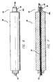
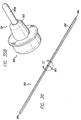
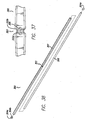
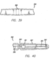
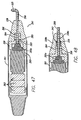
- FIGS. 36-45 show a threading device or rod 300 that includes eyelet 302 or groove 303 (referred to herein as a suture tie-off location) at a point that is about midway between the ends thereof.
- suture 150 is tied around threading device 300 and is received in groove 303.
- Groove 303 is preferably defined circumferentially around the outside of device 300. However the groove only extends partially around the device 300.
- the device 300 may also have a recess 305 defined therein in which the knot 150c is received. This reduces the profile of the knot 150c and helps prevent the knot 150c from catching on anything (ligaments, skin, suture, etc.) when threading device 300 is used.
- threading device 300 includes opposite ends or tips 304, tube 307, end caps 304a and light guide 306.
- Threading device 300 may be solid.
- the tips and light guide may be integral or the tips can be omitted.
- the threading device 300 can be solid metal with no lighting capabilities or can be formed completely of a solid (or plurality of components) made of a translucent or light conducting or transmissive material (such as plastic) so that the entire device lights up and/or so that the device is more flexible and easier and cheaper to manufacture.
- the ends or tips of the threading rod 300 are blunt.
- blunt means that the ends do not puncture the skin or any other part of the patient's anatomy without sufficient force (a force above that typically used in the procedure described below).
- a typical suture needle punctures the skin with very little pressure or force applied to it.
- the blunt ends of the present threading device 300 (whether flat or convex) do not puncture the skin when used as described below.
- Eyelet 302 may be formed so that when the knot 150c is tied therethrough, it is received in a recessed portion (now shown, but similar to recess 305).
- a suture 150 and threading device 300 can be formed as a unit.
- the suture 150 is permanently attached to the threading device 300 and the two can be provided to a surgeon as a unit.
- threading device 300 is malleable.
- tube 307 can be made of stainless steel, titanium or other metal and light guide 306 can be made of a plastic (e.g., acrylic, styrene, polycarbonate or the like) or glass.
- tube 307 can be tapered (or the entire device 300 can be tapered in the case of a solid rod) from the ends to groove 303, eyelet 302 or suture tie-off location (as shown in FIGS. 37 and 39 ).
- the rod tapers from a first location 333a to the left of the groove 303 toward the first end and the rod tapers from a second location to the right 333b of the groove 303 toward the second end. Therefore, the rod has a smaller diameter at the first and second ends than it does at the first and second locations. As is shown in FIGS.
- first and second locations 333a and 333b has a constant diameter. This prevents stress concentration in the center of the rod 300 and helps prevent failure of the rod during use. It will be understood that the first and second locations 333a and 333b can be located anywhere along the length of rod 300.
- threading device 300 is non-round. For example, it may be hexagonal.
- a female receiver 366 of instrument dock 364 of the handset 360 or 60 has a corresponding shape. This prevents threading device 300 from rotating when docked.
- only the ends of threading device 300 are polygonal. It will be understood that any way for keying the threading rod and preventing it from rotating is within the scope of the present invention.
- the instrument dock can have an elastomeric o-ring 335 therein that provides a friction fit with anything inserted therein.
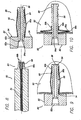
- tube 307 is hollow and light guide 306 runs through it.
- the ends 304 of tube 307 are preferably capped by end caps 304a.
- End caps 304a are preferably hollow, made of a transparent plastic and preferably include a flange 304b that is received in tube 307 in a press fit arrangement. Caps 304a can also be threaded or glued into the ends of tube 307. End caps 304a are bullet-shaped and provide total internal reflection.
- tube 307 is round, and light guide 306 is flush with the ends 304 of tube 307, and the recess described above is omitted.
- This embodiment also includes the taper locations 333a and 333b described above. However, locations 333a and 333b can be omitted, therefore, providing the tube 307, excluding groove 303 with a constant diameter.
- the caps 304a are omitted.
- the light guide 306 can be potted, which is an adhesive that fills the space between the light guide 306 and the inner diameter of the tube 307. It will be understood that the entire light guide 306 or just the ends can be potted.
- the ends 304 of the rod 300 may be ground, polished and buffed to promote light transmission and to make the ends of tube 307 and light guide 306 flush, as shown in FIG. 43 .
- the ends 304 can be flat or convex.
- the light guide 306 can be cladded. If a plastic light guide is used, the outside of the light guide 306 can be cladded. If a glass light guide is used, as is known in the art, the glass billet can be cladded before the glass light guide is drawn. The use of cladding is not a limitation on the present invention, however, if it is not used, the potting compound may detract from the light transmission and make it less efficient.
- the lighting device 360 may include a DC to DC converter to boost the voltage to the desired level for the high efficiency white LED.
- the numerical aperture of the light guide 306 may be matched as closely as possible by the light emitted from the LED. This helps maximize the efficiency of the light transmission.
- threading device 300 may include its own power supply 391 and light source 393.
- the power supply 391 and light source 393 e.g., LED's
- the threading device 300 can include an LED or the like at each end.
- the handset can reciprocate the threading device to help in passing the threading device subcutaneously.
- the reciprocating action allows the threading device to pass easily through fatty tissue, thus creating less collateral damage to blood vessels, nerve structures and other subcutaneous ligaments.
- the handset is powered to reciprocate the threading device back and forth during surgery.
- the threading device can be connected to the handle by a connector that is affixed to, integrally formed with, or selectively joinable to a reciprocating member.
- the handset may reciprocate or vibrate the threading device ultrasonically.
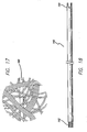
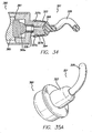
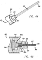
- FIGS. 33-35b show the clearing device 321, which is a blunt instrument for probing the puncture or access site and clearing ligaments and other obstructions.
- clearing device 321 includes a neck (also referred to as the docking portion) 323 and a clearing portion 325.
- Clearing portion 323 is preferably about the same diameter as threading rod 300, that way they both fit into the access sites.
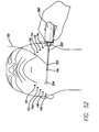
- clearing portion 325 is spiral shaped. This allows the surgeon to insert the clearing portion 325 into the access site 14 and sweep the area under the access site clear by rotating the device (see FIG. 51 for a figure depicting use of the clearing device 321).
- the clearing device 321 snap fits onto handset 360.
- neck 323 and instrument dock 364 include corresponding protrusions 327a and indentations 327b, as best shown in FIG. 34 .
- Clearing device 321 is preferably made of plastic, which allows flexibility for the snap fit arrangement, and also allows clearing device 321 to transilluminate. In use, light is emitted from instrument dock 364 and transilluminates the clearing device 321. Only the tip of the clearing device 321 is illuminated and the remainder of the device is opaque. This helps direct the light to the tip. Clearing device 321 can be made of metal.
- clearing device 321 can be removably affixed to handset 360 in other ways. For example, an arrangement where a portion of neck 323 is received in slots on the handset 360 (or vice versa) and then the clearing device is turned and locked into place can be utilized. Also, as shown in FIG. 32 , a threaded arrangement 329 is within the scope of the present invention. Clearing device 321 can also be designed to fit on handset 60.
- Clearing device 321 can be a rod that fits in female receiver 366, as shown in FIG. 46 .
- the clearing device 321 includes a neck (or docking portion) 323 and a clearing portion 323.
- the neck 323 can be keyed (similar to the threading device, described below) to prevent rotation when inserted into female receiver 366.
- FIGS. 35a and 35b show a clearing device with curved 325a and straight 325b clearing portions. These clearing portions can also be included on a clearing device that is received in female receiver 366 also.
- the handset 360 is generally the same as described above. As is shown in the figures, the instrument dock includes threads 329 and a circular female receiver 366. The handset 360 can also include a tail cone 337 as described above. The tail cone 337 can simply be for providing the surgeon with something to grip when rotating the clearing device or can be designed to actuate a latching switch for actuating the light source, as described above.
- the device may also include a nose cone 339 that can be threaded on the instrument dock 364.
- the nose cone 339 preferably includes gripping indentations 339a and has an axial opening 339c defined therethrough that is axially aligned with female receiver 366 when nose cone 339 is threaded onto instrument dock 364.
- the nose cone 339 provides a grip for the surgeon when using the handset 360. This allows the surgeon to hold the handset similar to the way that one would hold a pen.
- the clearing device 321 can have a neck 323 that fits into female receiver 366 and that includes a clearing portion 325 extending therefrom.
- the nose cone and clearing device can be formed as a unit, thereby creating a clearing device assembly 341.
- the neck 323 is inserted into female receiver 366, while the nose cone 339 is threaded onto instrument dock 364 simultaneously.
- O-ring 335 helps secure neck 323 within female receiver 366.
- Clearing portion 325 may extend in a curved path that defines a plane that is approximately perpendicular to the longitudinal axis of the neck.
- clearing device assembly 341 can include a light guide 306 extending therethrough for illuminating the tip.
- a separate nose cone 339b for securing threading rod 300 is also preferably used.
- the clearing device assembly 341 is unscrewed from instrument dock 364 and then nose cone 339b is screwed on.
- Nose cone 339b includes an o-ring 335 therein for helping secure threading rod 300 when inserted into opening 339c and female receiver 366, as shown in FIG. 48 .
- Nose cone 339b can be omitted.
- Nose cone 339b can include means for tightening the threading rod therein so that it is difficult to pull the threading rod out.
- the nose cone 339b may include a set screw, chuck, interior threads or the like.
- threading rod 300 can include securing channels 343 defined circumferentially therearound. When inserted into nose cone 339b or female receiver 366, one of the channels 343 receives o-ring 335, to help secure the threading rod 300 therein.
- the channels are located near both ends because the threading rod is reversible, as described below.
- the nose cone 339b or instrument dock 364 may include a metal ring 345 that is received in the channels 343, which provides a stronger snap fit arrangement than the o-ring.
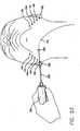
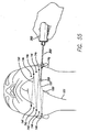
- the length of the threading rod 300 will change depending upon the type of procedure being performed (and the size of the patient's anatomy). It is important that the threading rod 300 be long enough so that as it is passed subcutaneously as one end emerges from an exit access site 14 that the other end extends out of the entry access site 14. For example, in the Percutaneous Trampoline Platysmaplasty, the threading rod 300 may be about nine inches long. With reference to FIG. 53 , this allows one end of the threading rod 300 to extend out of access site 14b and the opposite end to extend out of access site 14c simultaneously. In the MACS-lift, the threading rod 300 does not have to be as long. It should be understood that the threading devices 100 and 300 shown in the figures are not to scale.
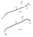
- the threading rod can be curved or bent.
- the ends 304 can be curved in different directions.
- This type of threading rod 300a may be solid or may have a light guide therein. The ends can be sharp or blunt. It may be difficult to transmit light through the ends 304, so an opening 347 can be made in the tube 307 to allow light to be emitted from a point spaced from the end 304.
- Threading rod 300a may be useful for abdominal surgery and may be thick and less malleable than the embodiments described above to strengthen the device.
- the threading rod 300b can have ends that curve in the same direction.
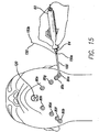
- FIG. 15 After first end 150a of the suture 150 is connected to eyelet 102, the handset 60 is grasped by the surgeon and the threading device is inserted through a first skin port 80a.
- the lighted tip 104 of threading device 100 illuminates the work area and transilluminates through the skin allowing the surgeon to determine the proper placement of the support matrix 200 and the location of the tip 104.
- port 80 may be clear for aiding in the passage of the threading device 100. In other words, when the tip 104 of threading device 100 gets close to port 80 it will transilluminate.
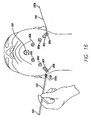
- the threading device 100 is preferably long enough that it can be threaded from one side of the jaw line to the other such that the tip 104 is brought out through a second skin port 80b on the opposite side of the jaw from which it was inserted. At this point, the tip 104 is grasped by the surgeon and the suture 150 is pulled through the area under the neck. Then the threading device 100 is disconnected from the handset 60 allowing the threading device 100 and the suture 150 to be pulled through the second skin port 80b, as is shown in FIG. 16 .
- the threading device 100 is then turned and reconnected to the handset 60 and is then reinserted through second skin port 80b and is passed subcutaneously to the contralateral side exiting through third skin port 80c.
- the threading device 100 is once again disconnected from the handset 60 and is reconnected after the threading device and suture 150 are pulled through third skin port 80c.
- the threading device 100 is turned and reconnected to the handset 60 and is then reinserted through third skin port 80c and is passed subcutaneously to the contralateral side exiting through fourth skin port 80d. At this point, the threading device 100 is once again disconnected from the handset 60 and is reconnected after the threading device and suture 150 are pulled through fourth skin port 80d.
- the threading device 100 is then turned and reconnected to the handset 60 and is then reinserted through fourth skin port 80d and is passed subcutaneously to the contralateral side exiting through fifth skin port 80e. At this point, the threading device 100 is once again disconnected from the handset 60 and is reconnected after the threading device and suture 150 are pulled through fifth skin port 80e.
- the threading device 100 is turned and reconnected to the handset 60 and is then reinserted through fifth skin port 80e and is passed subcutaneously to the midline sub-mental access site which preferably includes a threaded skin port 120 (described more fully hereinbelow).
- the threading device 100 and first end 150a of suture 150 are pulled through the threaded skin port 122 and the threading device is disconnected from the handset 60.
- the first end 150a of suture 150 is then cut from and/or untied from the threading device 100.
- the second end (or distal end) 150b of suture 150 which is extending from first skin port 80a is secured to the eyelet 102 of the threading device 100 and the threading device 100 is connected to the handset 60.
- the handset 60 is grasped by the surgeon and the threading device is inserted through the first skin port 80a and is passed subcutaneously to the contralateral side exiting through sixth skin port 80f.
- the threading device 100 is once again disconnected from the handset 60 and is reconnected after the threading device and suture 150 are pulled through sixth skin port 80f.
- the threading device 100 is turned and reconnected to the handset 60 and is then reinserted through sixth skin port 80f and is passed subcutaneously to the contralateral side exiting through seventh skin port 80g. At this point, the threading device 100 is once again disconnected from the handset 60 and is reconnected after the threading device and suture 150 are pulled through seventh skin port 80g.
- the threading device 100 is then turned and reconnected to the handset 60 and is then reinserted through seventh skin port 80f and is passed subcutaneously to the contralateral side exiting through eighth skin port 80h. At this point, the threading device 100 is once again disconnected from the handset 60 and is reconnected after the threading device and suture 150 are pulled through eighth skin port 80h.
- the threading device 100 is turned and reconnected to the handset 60 and is then reinserted through eighth skin port 80h and is passed subcutaneously to the threaded skin port 120 at the midline sub-mental access site.
- the threading device 100 and second end 150b of suture 150 are pulled through the threaded skin port 120 and the threading device is disconnected from the handset 60.
- the tube 84 on the skin ports 80 is long enough that when the threading device 100 is inserted therethrough the suture 150 will anchor itself by encircling the facial retaining ligaments during the procedure described above.
- the suture is secured on the facial retaining ligaments, thereby creating an anchor or pivot point.
- Transcutaneous light transmission from the tip 104 of the threading device 100 gives feedback allowing the surgeon to determine the location of the tip 104 as the support matrix 200 is weaved and created. This feedback allows the placement of each individual strand relative to areas of needed support. This allows placement of the suture strands 150 adjacent to the muscle, deep to the skin and fat layers.
- each port 80 the end of the tube 84 that is associated with the flange 82 has a beveled or tapered edge 84a, which helps prevent the tip 104 of the threading device 100 from catching inside the tunnel 86, during insertion.
- Two threading devices 100 that are each connected to an opposite end of the suture 150 can be used.
- the first threading device 100 does not have to be disconnected from the end of the suture 150 before the second end of the suture 150 is threaded through the skin.
- the suture 150 can come in a kit with two disposable threading devices 100 attached to the opposite ends 150a and 150b. After forming the matrix 200, the threading devices 100 can be cut from the suture 150 and then the suture can be tied.
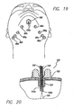
- FIGS. 19-23 show the threaded skin port 120 used for the midline sub-mental access site.
- the threaded skin port 120 is inserted at the same time as the skin ports 80 described above.
- the port 120 includes a flange 122 having a tube 124 extending therefrom.
- the tube 124 is preferably threaded 126.
- the tube 124 and flange 122 cooperate to define a tunnel 128 therethrough.
- the portion of the tunnel 128 in the flange 122 includes a beveled or tapered edge 128a.
- the port 120 may include a pair of handle portions 130 extending upwardly from the flange 122 that aid the surgeon in threading the port 120 into the midline sub-mental access site.
- the handle portions 130 are not a limitation and can be omitted.
- any skin port that allows access through the skin is within the scope of the present invention.
- skin port 80 or something similar can be used at the midline sub-mental access site.
- Port 120 can be used at access site 14.
- Port 120 is clear for aiding in the passage of the threading device 100. In other words, when the tip 104 of threading device 100 gets close to the port 120 it will transilluminate.
- the tube 124 is inserted into the midline sub-mental access site.
- the handle portions 130 are grasped and the port 120 is turned so that the threads 126 are threaded into the skin until the bottom surface of the flange 122 rests against the outer surface of the skin.
- the flange may include a threaded interior that engages the threads on the exterior of the tube.
- the distal ends of the folding members are connected to a ring that is not internally threaded. This ring allows the tube to rotate therein, but (because it is not internally threaded) does not cause the ring to ride up the threads of the tube.
- the opposite ends of the folding members are connected to the flange.
- a knot positioning implement 140 is shown and described. After both ends 150a and 150b of the suture 150 are threaded and the support matrix 200 has been created, the two suture ends 150a and 150b are brought out through the midline sub-mental access site (through port 120), as is shown in FIG. 19 . A single throw knot 150c is placed (it will be understood that the type of knot is not a limitation on the present invention) and the knot positioning implement 140 is utilized to set the knot 150c.
- the knot positioning implement 140 may include a fiber optic core 152 and an opening 152a through which light is transmitted to illuminate the work area when placing the knot 150c.
- threaded port 120 is twisted out of the access site and the other skin ports 80 are removed using the handset 60.
- the male connector 68 is inserted into the port 80 so that the ridge 68a snaps into the indented ring 82a and the teeth 68b and 82b engage one another.
- the handset 60 is then twisted, thereby turning tube 84 and causing the internally threaded ring 90b to travel back down threads 88 and unfolding folding the folding members 90a.
- the ports 80 can be removed by hand.
- Handset 360 and threading device 300 can be used.
- the majority of the access sites 14 are above the submandibular border.
- the threading device 300 requires intermittent access sites 14 under the jaw to allow the threading rod to be redirected around the curvature of the neck (the exemplary access site showing this is marked 14a).
- the surgeon may choose to use other access sites under the patient's jaw or in other locations as needed to allow the threading rod to be redirected.
- the surgeon may want to use clearing device 321 (or clearing device assembly 341) to clear dermal attachments under the area adjacent the access sites 14.
- clearing device 321 or clearing device assembly 3411
- the surgeon can also use nose cone 339 or 339b to help secure the threading rod 300 and aid in the manipulation of the handset 360 during surgery.
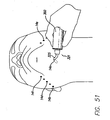
- the surgeon creates an access site 14a under the chin.
- the handset 360 is illuminated (e.g., by pulling the rip cord, twisting or pushing the tail cone or otherwise switching the light source on) and the threading device 300 is inserted into the handset 360.
- Threading device 300 is inserted through access site 14a, as shown in FIG. 52 .
- the lighted tip 304 of threading device 300 illuminates the work area and transilluminates through the skin allowing the surgeon to determine the proper placement of the support matrix 200 and the location of the tip 304.
- the threading rod is then brought out through a second access site 14b and a portion of the suture is pulled through second access site 14b. Enough of the suture is pulled through second access site 14b so that just enough of the suture is still sticking out of site 14a so that the suture can be tied off at the end of the procedure (described below). To prevent the end of the suture from being pulled into first access site 14a it can be anchored by something, such as a hemostat. It will be understood that because the suture is tied in the middle of the threading rod 300, the surgeon does not have to pull the entire threading rod out of the access site.
- the surgeon can pivot the rod in the desired direction and then start pushing the rod back through the access site. This action allows the suture to anchor on the ligaments under the skin near the access site. It will be understood that because the threading rod 300 has the suture attached near the middle thereof and it is double ended, it does not have to be turned around each time it is brought out from under the patient's skin. However, the surgeon may turn the threading rod around as desired.
- the surgeon Before pushing the threading rod back into second access site 14b, the surgeon places the handset on the end of the threading rod to illuminate the tip 304, as shown in FIG. 53 .
- the threading rod is then threaded from site 14b to site 14a, is pivoted around and is passed subcutaneously to third access site 14c.
- the surgeon may thread straight from site 14b to site 14c without pivoting the rod at 14a.
- This is repeated for fourth, fifth and sixth access sites 14d, 14e and 14f and eventually the threading rod is brought out through the sub-mental access site (each time, the surgeon does not always have to come back out through site 14a but may go directly to the next site in the "shoe lace").
- the handset is taken on and off of the threading rod as desired during this procedure so that one of the tips 304 is lit as desired.
- the suture 150 is then cut from the threading rod.
- the first suture 150 is passed around the facial retaining ligaments adjacent thereto, thereby creating an anchor or pivot point.
- a second suture 151 is then tied to the threading rod 300 and the threading rod is inserted into first access site 14a. It is then passed subcutaneously to seventh access site 14g. Similar to the procedure described above for the first suture 150, the second suture 151 is then threaded to eighth, ninth, tenth and eleventh access sites 14h, 14i, 14j and 14k (see FIG. 55 ) and is finally brought out of the midline sub-mental access site. The ends of the sutures 150 and 151 extending out of site 14a are then tied together, thereby, completing the matrix 200 (see FIG. 56 ). The knot 150c is then pushed through the site 14a and under the skin (e.g., using the clearing device or threading rod).
- the surgeon can pull on the ends of the sutures 150 and 151 extending out of the sub-mental access site to place the desired tension on the matrix 200. Once this is done, the ends of the sutures 150 and 151 are tied together and the knot 150c is pushed through the site and under the skin.
- the surgery can be performed without the handset. Some surgeons may want to use the threading device alone without using the handset to illuminate the tips. In this situation a solid threading device or a threading device with self-contained power and light sources can be used.
- the threading device 300 can be used for other types of surgery. For example, it can be used to place suture systems that are commonly utilized in plastic surgery that previously required the opening or elevation of the facial, neck skin and/or other areas of the body. Examples of this include the use of this device or system for placement of a neck defining suture or it can be used in the MACS-lift (minimal access cranial suspension), which is described in The MACS-lift Short Scar Rhytidectomy by Patrick Tonnard, M.D.
- the neck defining suture is described in the article Suture Suspension Platysmaplasty for Neck Rejuvenation Revisited: Technical Fine Points for Improving Outcomes by Vincent Giampapa, M.D., Vietnamesenis Bitzos, M.D., Oscar Ramirez, M.D., and Mark Granick, M.D., Aesthetic Plastic Surgery, Vol. 29, pgs. 341-350, 2005 . .
- the procedure can be performed by making a small incision behind the ears and then threading the suture subcutaneously under the mandible using the threading rod 300 and necessary pivot points (access sites) as desired.
- the suture that is used in the procedure is a 4.0 braided polyester suture.
- the suture design may contain at least one fiberoptic strand 150d intertwined with the non-fiberoptic strands.
- the suture 150 is braided as is known in the art with one, two or three fiberoptic strands and one or two non-fiberoptic strands, as is desired. This aids in the transillumination of the suture 150 to check subcutaneous placement after the suture 150 has been placed.
- the fiberoptic strand 150d will illuminate when the handset 60 fiberoptic light coupled with the knot placement implement 140 is approximated to the suture during tying. Light transmitted to the suture allows the surgeon to visualize placement of the support matrix 200 as it is secured.
- the non-fiberoptic strands can be made of any material known in the art, such as nylon, polypropylene, or other non-absorbable material.
- suture placement can be confirmed by placing the handset 60 or 360 (or any light source) at one of the ends 150a or 150b of the suture 150, thereby transmitting light down the fiberoptic strand 150d to check placement of the suture 150.
- suture illumination gives the surgeon feedback relating to the anatomical movement of each pivot point.
- the fiberoptic suture can be utilized in all areas of surgery or other materials where a lit binding material is needed, and not just in the technique described herein.
- the threading device may be a straight or curved needle.
- Application of light energy during a surgical procedure will confirm suture placement and accuracy.
- Application of light post-operatively could allow surgeons to understand the evolution of suture placement related to time and aging.
- the neck skin can be elevated from the platysma muscle via an incision similar to that used in the standard procedure discussed above to allow the surgeon to visualize the operative field and then the suture matrix can be placed through the ports 80 and/or access sites 14.
- kits can be sold in kits.
- a kit with all or any combination of the instruments including the tape 10 or 310, a marking pen, lancet 40, handset 60 or 360, skin ports 80, threading device 100 or 300, threaded skin port 120, knot positioning implement 140, suture 150 or 151, nose cone 339 or 339, clearing device 321, clearing device assembly 341 or any other instrument described herein can be sold.
Landscapes
- Health & Medical Sciences (AREA)
- Surgery (AREA)
- Life Sciences & Earth Sciences (AREA)
- Medical Informatics (AREA)
- Nuclear Medicine, Radiotherapy & Molecular Imaging (AREA)
- Engineering & Computer Science (AREA)
- Biomedical Technology (AREA)
- Heart & Thoracic Surgery (AREA)
- Molecular Biology (AREA)
- Animal Behavior & Ethology (AREA)
- General Health & Medical Sciences (AREA)
- Public Health (AREA)
- Veterinary Medicine (AREA)
- Rheumatology (AREA)
- Surgical Instruments (AREA)
- Blow-Moulding Or Thermoforming Of Plastics Or The Like (AREA)
Applications Claiming Priority (12)
| Application Number | Priority Date | Filing Date | Title |
|---|---|---|---|
| US11/566,613 US20080132946A1 (en) | 2006-12-04 | 2006-12-04 | Skin port |
| US11/566,625 US20080132920A1 (en) | 2006-12-04 | 2006-12-04 | Surgical instruments for positioning suture knots |
| US11/566,618 US7566340B2 (en) | 2006-12-04 | 2006-12-04 | Surgical threading device and method for using same |
| US11/566,530 US20080132917A1 (en) | 2006-12-04 | 2006-12-04 | Surgical instrument docking device |
| US11/566,432 US8826914B2 (en) | 2006-12-04 | 2006-12-04 | Surgical tape and method for using same |
| US11/566,499 US20080132931A1 (en) | 2006-12-04 | 2006-12-04 | Skin puncturing device |
| US11/566,386 US7740647B2 (en) | 2006-12-04 | 2006-12-04 | Necklift procedure and instruments for performing same |
| US11/566,622 US20080132942A1 (en) | 2006-12-04 | 2006-12-04 | Suture and method for using same |
| US11/950,404 US20080132905A1 (en) | 2006-12-04 | 2007-12-04 | Surgical clearing device and method for using same |
| US11/950,378 US7842052B2 (en) | 2006-12-04 | 2007-12-04 | Necklift procedure and instruments for performing same |
| US11/950,387 US20080131659A1 (en) | 2006-12-04 | 2007-12-04 | Laminated surgical tape and method for using same |
| PCT/US2007/086429 WO2008070691A2 (en) | 2006-12-04 | 2007-12-04 | Necklift procedure and instruments for performing same |
Publications (3)
| Publication Number | Publication Date |
|---|---|
| EP2091443A2 EP2091443A2 (en) | 2009-08-26 |
| EP2091443A4 EP2091443A4 (en) | 2011-05-11 |
| EP2091443B1 true EP2091443B1 (en) | 2012-04-25 |
Family
ID=65728966
Family Applications (1)
| Application Number | Title | Priority Date | Filing Date |
|---|---|---|---|
| EP07865199A Active EP2091443B1 (en) | 2006-12-04 | 2007-12-04 | Necklift instrument |
Country Status (10)
| Country | Link |
|---|---|
| US (8) | US20080132920A1 (enExample) |
| EP (1) | EP2091443B1 (enExample) |
| JP (1) | JP5191994B2 (enExample) |
| KR (1) | KR20090098858A (enExample) |
| CN (1) | CN101917910A (enExample) |
| AT (1) | ATE554818T1 (enExample) |
| AU (1) | AU2007329394A1 (enExample) |
| CA (1) | CA2672724C (enExample) |
| MX (1) | MX2009005922A (enExample) |
| WO (1) | WO2008070691A2 (enExample) |
Families Citing this family (26)
| Publication number | Priority date | Publication date | Assignee | Title |
|---|---|---|---|---|
| US9033999B2 (en) | 2006-12-04 | 2015-05-19 | Implicitcare, Llc | Surgical threading device with removable suture |
| US8951271B2 (en) | 2006-12-04 | 2015-02-10 | Implicitcare, Llc | Surgical threading device and method for using same |
| US8025671B2 (en) * | 2006-12-04 | 2011-09-27 | Implicitcare, Llc | Surgical threading device and method for using same |
| GB2479308B (en) * | 2007-04-19 | 2012-06-06 | Searete Llc | Fiducials for placement of tissue closures |
| US20080262390A1 (en) * | 2007-04-19 | 2008-10-23 | Searete Llc, A Limited Liability Corporation Of The State Of Delaware | Fiducials for placement of tissue closures |
| US20080262524A1 (en) * | 2007-04-19 | 2008-10-23 | Searete Llc, A Limited Liability Corporation Of The State Of Delaware | Systems and methods for closing of fascia |
| PL2139434T3 (pl) * | 2007-04-20 | 2013-03-29 | Woodwelding Ag | System implantu do mocowania implantu do tkanki kostnej |
| KR101580098B1 (ko) | 2007-07-26 | 2015-12-28 | 알파 사이언티픽 코오포레이션 | 외과수술 봉합장치 및 이와 함께 사용되는 도구들 |
| US9226748B2 (en) * | 2007-07-26 | 2016-01-05 | Alpha Scientific Corporation | Surgical suturing device, method and tools used therewith |
| US8255192B2 (en) * | 2008-06-27 | 2012-08-28 | Microsoft Corporation | Analytical map models |
| EP2445416A1 (en) * | 2009-06-21 | 2012-05-02 | Aesthetics Point Ltd. | An implanted medical device useful for cosmetic surgery |
| WO2011130536A2 (en) * | 2010-04-14 | 2011-10-20 | Northwestern University | Triple balloon occlusion and infusion catheter |
| US8905033B2 (en) * | 2011-09-28 | 2014-12-09 | Ethicon, Inc. | Modular tissue securement systems |
| US10470760B2 (en) | 2011-12-08 | 2019-11-12 | Ethicon, Inc. | Modified tissue securement fibers |
| US10143531B2 (en) | 2012-09-28 | 2018-12-04 | Beekley Corporation | Skin marking porous grid and related method of use |
| US9636110B2 (en) | 2013-03-13 | 2017-05-02 | Alpha Scientific Corporation | Structural support incorporating multiple strands |
| WO2014145724A2 (en) | 2013-03-15 | 2014-09-18 | Alpha Scientific Corporation | Surgical suturing device with transverse engagement |
| US9597105B2 (en) | 2014-04-17 | 2017-03-21 | Covidien Lp | Vibrating surgical instruments for blunt dissection |
| US9603616B2 (en) | 2014-04-17 | 2017-03-28 | Covidien Lp | Vibrating surgical instruments for blunt dissection and methods for use thereof |
| US10064642B2 (en) | 2015-03-04 | 2018-09-04 | Covidien Lp | Surgical instrument for dissecting tissue |
| CN106473785A (zh) * | 2015-08-27 | 2017-03-08 | 李胜文 | 一种生物可吸收缝合组件的钉仓 |
| CN107897029A (zh) * | 2018-01-08 | 2018-04-13 | 上海犊瑞乳品设备有限公司 | 犊牛饲喂装置 |
| US11576666B2 (en) | 2019-10-04 | 2023-02-14 | Arthrex, Inc | Surgical constructs for tissue fixation and methods of tissue repairs |
| US11297285B2 (en) | 2020-03-27 | 2022-04-05 | Sean Solon Pierce | Dental and medical loupe system for lighting control, streaming, and augmented reality assisted procedures |
| US20210338236A1 (en) * | 2020-04-29 | 2021-11-04 | Greene Technologies, LLC | Thread lift cannula and method of performing a thread lift |
| WO2025072056A1 (en) * | 2023-09-27 | 2025-04-03 | Providence Medical Technology, Inc. | Spinal portal and visualization |
Family Cites Families (95)
| Publication number | Priority date | Publication date | Assignee | Title |
|---|---|---|---|---|
| US1353587A (en) | 1917-02-20 | 1920-09-21 | White S Dental Mfg Co | Saliva-ejector |
| US1358753A (en) * | 1920-05-24 | 1920-11-16 | Benjamin F Killam | Elastic shoe-lace |
| US1901737A (en) * | 1932-05-18 | 1933-03-14 | Sonoco Products Co | Spool |
| US1965651A (en) * | 1933-03-24 | 1934-07-10 | Patrick T Kelley | Spool |
| US2121234A (en) * | 1936-06-27 | 1938-06-21 | Hubbard Spool Company | Spool |
| US2399545A (en) * | 1942-11-18 | 1946-04-30 | Bernard E Davis | Adhesive tape |
| US2837297A (en) * | 1954-04-26 | 1958-06-03 | Clarence B Moss | Spool with threadably mounted end members |
| US3432116A (en) * | 1967-07-24 | 1969-03-11 | Marguerite M Lauen | Spool construction having a snap-off end portion |
| CH478693A (de) | 1967-08-14 | 1969-09-30 | Weber Alwin | Ausgusshülse für aus dünnwandigem Papier, Karton oder Kunststoffen bestehenden durchstechbaren Beuteln und Behältern für Flüssigkeiten |
| US3694291A (en) * | 1968-03-27 | 1972-09-26 | Tektronix Inc | Apparatus for making light pipes |
| US3544406A (en) * | 1968-03-27 | 1970-12-01 | Tektronix Inc | Method and apparatus for making light pipes |
| US3983878A (en) * | 1973-12-10 | 1976-10-05 | Claude Edward Kawchitch | Surgical appliance |
| US4351333A (en) * | 1975-10-28 | 1982-09-28 | Harrison Lazarus | Peritoneal fluid treatment apparatus, package and method |
| GB2031316B (en) * | 1978-10-16 | 1982-11-24 | Arrowlite Tools | Illuminated hand tools |
| US5435805A (en) * | 1992-08-12 | 1995-07-25 | Vidamed, Inc. | Medical probe device with optical viewing capability |
| US4690138A (en) * | 1984-11-01 | 1987-09-01 | Heyden Eugene L | Marking system for tube placement |
| US4736743A (en) * | 1986-05-12 | 1988-04-12 | Surgical Laser Technology, Inc. | Vaporization contact laser probe |
| US4886079A (en) * | 1988-02-10 | 1989-12-12 | Mooney Lillian A | Cosmetic template |
| US4957124A (en) * | 1988-02-10 | 1990-09-18 | Mooney Lillian A | Template |
| US5044755A (en) * | 1989-03-03 | 1991-09-03 | Lt Industries | Probe for transmitting and receiving light from a sample |
| US5077901A (en) * | 1990-05-18 | 1992-01-07 | Warner Joseph A | Ceramic blades and production methodology therefor |
| US5653725A (en) * | 1990-07-12 | 1997-08-05 | University Of Miami | Instrument for initiating an intralamellar channel |
| CA2053642C (en) | 1990-12-13 | 2003-12-30 | George R. Proto | Method and apparatus for tipping sutures |
| US5217451A (en) * | 1991-05-24 | 1993-06-08 | Dexide, Inc. | Gear activated trocar assembly |
| US5391175A (en) * | 1991-11-29 | 1995-02-21 | Sharpe Endosurgical Corporation | Method of using an endoknot pusher surgical instrument |
| GR930100244A (el) | 1992-06-30 | 1994-02-28 | Ethicon Inc | Εύκαμπτο ενδοσκοπικό χειρουργικό στόμιο εισόδου. |
| US6010515A (en) * | 1993-09-03 | 2000-01-04 | University College London | Device for use in tying knots |
| US5772597A (en) | 1992-09-14 | 1998-06-30 | Sextant Medical Corporation | Surgical tool end effector |
| US5222508A (en) * | 1992-10-09 | 1993-06-29 | Osvaldo Contarini | Method for suturing punctures of the human body |
| US5337735A (en) * | 1992-12-28 | 1994-08-16 | Albert Salerno | Fiber-lighted stylet |
| US5540718A (en) * | 1993-09-20 | 1996-07-30 | Bartlett; Edwin C. | Apparatus and method for anchoring sutures |
| EP0673627B1 (en) * | 1994-03-23 | 2000-01-05 | Yasuo Hashimoto | Catheter with optical fiber |
| WO1995032669A1 (en) | 1994-06-01 | 1995-12-07 | Perclose, Inc. | Apparatus and method for advancing surgical knots |
| JP3798838B2 (ja) * | 1995-01-20 | 2006-07-19 | オリンパス株式会社 | 結紮装置 |
| US6185356B1 (en) | 1995-06-27 | 2001-02-06 | Lumitex, Inc. | Protective cover for a lighting device |
| JPH09201362A (ja) * | 1996-01-25 | 1997-08-05 | Manabu Maeda | 手術用縫合針 |
| US5697950A (en) * | 1996-02-07 | 1997-12-16 | Linvatec Corporation | Pre-loaded suture anchor |
| US5971960A (en) * | 1996-03-12 | 1999-10-26 | Heartport, Inc. | Trocar with expandable members for retaining the trocar |
| US5879306A (en) * | 1996-06-13 | 1999-03-09 | Stryker Corporation | Infrared system for visualizing body members |
| US5728103A (en) * | 1996-08-23 | 1998-03-17 | Applied Medical Technology, Inc. | Implantable subcutaneous access device and method of using same |
| US5836909A (en) * | 1996-09-13 | 1998-11-17 | Cosmescu; Ioan | Automatic fluid control system for use in open and laparoscopic laser surgery and electrosurgery and method therefor |
| US6162211A (en) | 1996-12-05 | 2000-12-19 | Thermolase Corporation | Skin enhancement using laser light |
| US5868665A (en) * | 1996-12-30 | 1999-02-09 | Biggs; Robert C. | Endocoupler system |
| US20020019670A1 (en) * | 1997-02-28 | 2002-02-14 | Jerald M. Crawley | Implantable tissue augmentation device |
| DE19726141A1 (de) * | 1997-06-19 | 1999-01-28 | Daum Gmbh | Neurotrokar |
| US5951543A (en) | 1997-06-30 | 1999-09-14 | Clinicon Corporation | Delivery system and method for surgical laser |
| US7306559B2 (en) | 1997-07-02 | 2007-12-11 | Lumitex, Inc. | Illuminated surgical retractor |
| US5941855A (en) | 1997-10-03 | 1999-08-24 | Applied Medical Technology, Inc. | Gastrostomy device package and method of assembly |
| US5921673A (en) * | 1997-11-13 | 1999-07-13 | Habel; David M. | Illuminated threading tool |
| US6432970B2 (en) * | 1998-04-09 | 2002-08-13 | Johns Hopkins University School Of Medicine | Inhibitors of hedgehog signaling pathways, compositions and uses related thereto |
| US7494488B2 (en) * | 1998-05-28 | 2009-02-24 | Pearl Technology Holdings, Llc | Facial tissue strengthening and tightening device and methods |
| US6432101B1 (en) * | 1998-05-28 | 2002-08-13 | Pearl Technology Holdings, Llc | Surgical device for performing face-lifting using electromagnetic radiation |
| US6391023B1 (en) * | 1998-05-28 | 2002-05-21 | Pearl Technology Holdings, Llc | Thermal radiation facelift device |
| US6029323A (en) * | 1998-06-15 | 2000-02-29 | Dickie; Robert G. | Positive lace zone isolation lock system and method |
| US6062785A (en) * | 1998-08-17 | 2000-05-16 | Mcdermott; Troy | Anchoring fastener |
| SE517169C2 (sv) * | 1998-10-23 | 2002-04-23 | Prisell Ab P | Mall och stans för att indikera samt borttaga en bit hud |
| US6245091B1 (en) * | 1999-02-19 | 2001-06-12 | Frank Hoffman | Vibrating suction surgical needle |
| US6270491B1 (en) | 1999-04-06 | 2001-08-07 | Duke University | Intensity controllable hand-held surgical light |
| US6273894B1 (en) * | 1999-07-22 | 2001-08-14 | Staar Surgical Company, Inc. | Vacuum cannula apparatus and method for positioning an intraocular lens in the eye |
| US6325522B1 (en) * | 1999-09-20 | 2001-12-04 | Harald Walian | Hand held device providing effective site illumination |
| CN101238998A (zh) * | 1999-11-15 | 2008-08-13 | 维尔克工业有限公司 | 皮肤附着件 |
| US20050099824A1 (en) * | 2000-08-04 | 2005-05-12 | Color Kinetics, Inc. | Methods and systems for medical lighting |
| KR100774534B1 (ko) * | 1999-12-30 | 2007-11-08 | 펄 테크놀러지 홀딩스, 엘엘씨 | 안면 당김성형 장치 |
| US20020064302A1 (en) * | 2000-04-10 | 2002-05-30 | Massengill R. Kemp | Virtual cosmetic autosurgery via telemedicine |
| ATE300244T1 (de) * | 2000-05-10 | 2005-08-15 | Canica Design Inc | Vorrichtung zum bewegen und strecken von gewebe |
| US20020029011A1 (en) * | 2000-09-05 | 2002-03-07 | Dyer Wallace K. | Methods and devices for surgery |
| US20020147382A1 (en) * | 2001-01-23 | 2002-10-10 | Neisz Johann J. | Surgical articles and methods |
| US6500184B1 (en) | 2001-01-31 | 2002-12-31 | Yung C. Chan | Suturing apparatus and method of suturing |
| US6478442B2 (en) * | 2001-04-04 | 2002-11-12 | Sheng Ho Chen | Screwdriver having a light emitting device |
| US20020198544A1 (en) * | 2001-06-22 | 2002-12-26 | Renan Uflacker | Percutaneous facelift device |
| JP4473115B2 (ja) * | 2002-05-17 | 2010-06-02 | タイコ ヘルスケア グループ エルピー | 内視鏡的な器官牽引システムおよびその使用方法 |
| WO2003103733A1 (fr) * | 2002-06-07 | 2003-12-18 | Marlen Andreevich Sulamanidze | Fil chirurgical ≤ aptos ≥ pour operations de chirurgie esthetique |
| ITGE20020056A1 (it) * | 2002-06-26 | 2003-12-29 | Sergio Capurro | Ago atraumatico a due punte per chirurgia. |
| US6932834B2 (en) | 2002-06-27 | 2005-08-23 | Ethicon, Inc. | Suture anchor |
| US7021808B2 (en) * | 2002-10-08 | 2006-04-04 | Currie Robert M | Illuminated rope |
| US20040122451A1 (en) | 2002-12-23 | 2004-06-24 | Wood Timothy J. | Method and device for closing and fusing suture loops |
| US7060079B2 (en) * | 2003-01-03 | 2006-06-13 | Eye Plastic Surgery, Ltd. | Surgical instrument for endoscopic suturing of deep subcutaneous tissue |
| US7344554B2 (en) * | 2003-02-26 | 2008-03-18 | Ams Research Corporation | Keith needle for furlow insertion tool |
| US7144412B2 (en) * | 2003-06-25 | 2006-12-05 | Wolf Medical Enterprises, Inc. | Gold suture and method of use in wound closure |
| US20040267315A1 (en) * | 2003-06-25 | 2004-12-30 | Wolf Bradley R. | Braided gold suture and method of use |
| US6945777B2 (en) | 2003-09-09 | 2005-09-20 | Oralum, Llc | Floss for light treatment of oral structures |
| US7613523B2 (en) | 2003-12-11 | 2009-11-03 | Apsara Medical Corporation | Aesthetic thermal sculpting of skin |
| WO2005069743A2 (en) * | 2004-01-23 | 2005-08-04 | Chalam Mahadevan | Suture needle and suture assembly |
| US20050203562A1 (en) * | 2004-03-09 | 2005-09-15 | Palmer Joetta R. | Lighted dissector and method for use |
| US8236027B2 (en) * | 2004-04-07 | 2012-08-07 | Tze Liang Woffles Wu | Surgical thread |
| WO2005096955A1 (en) * | 2004-04-07 | 2005-10-20 | Tze Liang Woffles Wu | Surgical thread |
| US20050248933A1 (en) * | 2004-05-07 | 2005-11-10 | Chen Chang H | Light emitting device capable of being combined to a tool |
| EP1761176B1 (en) * | 2004-05-14 | 2013-09-18 | Ethicon, LLC | Suture devices |
| US7468068B2 (en) * | 2004-06-30 | 2008-12-23 | Alwin Kolster | Suture for wound closure, tissue approximation, tissue support, suspension and/or fixation |
| JP2006088584A (ja) * | 2004-09-24 | 2006-04-06 | Brother Ind Ltd | 印刷装置 |
| US7082690B1 (en) * | 2005-01-13 | 2006-08-01 | Bahram Khoshnood | Ambient light collecting sight pin for a bow sight |
| ES2305943T3 (es) * | 2005-05-20 | 2008-11-01 | F. Hoffmann-La Roche Ag | Sistema de lancetas con proteccion esteril. |
| US7270439B2 (en) | 2005-06-13 | 2007-09-18 | Horrell Robin S | Compact lighting system attachable to a surgical tool and method of use thereof |
| CA2550752C (en) * | 2005-06-28 | 2014-09-09 | Sherwood Services Ag | Illuminated ivs tunneling device |
| US8721666B2 (en) * | 2007-09-26 | 2014-05-13 | Ethicon, Inc. | Method of facial reconstructive surgery using a self-anchoring tissue lifting device |
-
2006
- 2006-12-04 US US11/566,625 patent/US20080132920A1/en not_active Abandoned
- 2006-12-04 US US11/566,618 patent/US7566340B2/en not_active Expired - Fee Related
-
2007
- 2007-12-04 CA CA2672724A patent/CA2672724C/en active Active
- 2007-12-04 US US11/950,404 patent/US20080132905A1/en not_active Abandoned
- 2007-12-04 AT AT07865199T patent/ATE554818T1/de active
- 2007-12-04 US US11/950,378 patent/US7842052B2/en active Active
- 2007-12-04 US US11/950,401 patent/US7833233B2/en active Active
- 2007-12-04 JP JP2009540435A patent/JP5191994B2/ja active Active
- 2007-12-04 WO PCT/US2007/086429 patent/WO2008070691A2/en not_active Ceased
- 2007-12-04 US US11/950,396 patent/US7914191B2/en active Active
- 2007-12-04 US US11/950,387 patent/US20080131659A1/en not_active Abandoned
- 2007-12-04 CN CN2007800507086A patent/CN101917910A/zh active Pending
- 2007-12-04 MX MX2009005922A patent/MX2009005922A/es active IP Right Grant
- 2007-12-04 EP EP07865199A patent/EP2091443B1/en active Active
- 2007-12-04 AU AU2007329394A patent/AU2007329394A1/en not_active Abandoned
- 2007-12-04 KR KR1020097013992A patent/KR20090098858A/ko not_active Ceased
-
2009
- 2009-06-01 US US12/476,113 patent/US20090248072A1/en not_active Abandoned
Also Published As
| Publication number | Publication date |
|---|---|
| US20080132921A1 (en) | 2008-06-05 |
| CA2672724A1 (en) | 2008-06-12 |
| WO2008070691A2 (en) | 2008-06-12 |
| KR20090098858A (ko) | 2009-09-17 |
| CN101917910A (zh) | 2010-12-15 |
| US7833233B2 (en) | 2010-11-16 |
| US20090248072A1 (en) | 2009-10-01 |
| US20080132916A1 (en) | 2008-06-05 |
| US20080131659A1 (en) | 2008-06-05 |
| US20080132905A1 (en) | 2008-06-05 |
| US7566340B2 (en) | 2009-07-28 |
| WO2008070691A3 (en) | 2010-06-17 |
| AU2007329394A1 (en) | 2008-06-12 |
| ATE554818T1 (de) | 2012-05-15 |
| US20080132920A1 (en) | 2008-06-05 |
| EP2091443A2 (en) | 2009-08-26 |
| JP5191994B2 (ja) | 2013-05-08 |
| CA2672724C (en) | 2014-02-04 |
| EP2091443A4 (en) | 2011-05-11 |
| US7914191B2 (en) | 2011-03-29 |
| JP2011502549A (ja) | 2011-01-27 |
| US7842052B2 (en) | 2010-11-30 |
| US20080132918A1 (en) | 2008-06-05 |
| US20080132947A1 (en) | 2008-06-05 |
| MX2009005922A (es) | 2009-08-24 |
Similar Documents
| Publication | Publication Date | Title |
|---|---|---|
| EP2091443B1 (en) | Necklift instrument | |
| US8025671B2 (en) | Surgical threading device and method for using same | |
| US5997554A (en) | Surgical template and surgical method employing same | |
| US6042583A (en) | Bone anchor-insertion tool and surgical method employing same | |
| EP2662030B1 (en) | Systems and devices for securing tissue using snare assemblies and soft anchors | |
| US9033999B2 (en) | Surgical threading device with removable suture | |
| US7740647B2 (en) | Necklift procedure and instruments for performing same | |
| US8951271B2 (en) | Surgical threading device and method for using same | |
| US20080132931A1 (en) | Skin puncturing device | |
| US20080132946A1 (en) | Skin port | |
| BRPI0720186A2 (pt) | Procedimento de lifting de pescoço e instrumentos para executar o mesmo | |
| TW200924693A (en) | Necklift procedure and instruments for performing same |
Legal Events
| Date | Code | Title | Description |
|---|---|---|---|
| PUAI | Public reference made under article 153(3) epc to a published international application that has entered the european phase |
Free format text: ORIGINAL CODE: 0009012 |
|
| 17P | Request for examination filed |
Effective date: 20090630 |
|
| AK | Designated contracting states |
Kind code of ref document: A2 Designated state(s): AT BE BG CH CY CZ DE DK EE ES FI FR GB GR HU IE IS IT LI LT LU LV MC MT NL PL PT RO SE SI SK TR |
|
| RIN1 | Information on inventor provided before grant (corrected) |
Inventor name: MUELLER, GREGORY, PAUL Inventor name: STONE, CORBETT |
|
| DAX | Request for extension of the european patent (deleted) | ||
| R17D | Deferred search report published (corrected) |
Effective date: 20100617 |
|
| RIC1 | Information provided on ipc code assigned before grant |
Ipc: A61M 25/00 20060101AFI20100707BHEP |
|
| A4 | Supplementary search report drawn up and despatched |
Effective date: 20110411 |
|
| GRAP | Despatch of communication of intention to grant a patent |
Free format text: ORIGINAL CODE: EPIDOSNIGR1 |
|
| RTI1 | Title (correction) |
Free format text: NECKLIFT INSTRUMENT |
|
| GRAC | Information related to communication of intention to grant a patent modified |
Free format text: ORIGINAL CODE: EPIDOSCIGR1 |
|
| GRAS | Grant fee paid |
Free format text: ORIGINAL CODE: EPIDOSNIGR3 |
|
| GRAA | (expected) grant |
Free format text: ORIGINAL CODE: 0009210 |
|
| AK | Designated contracting states |
Kind code of ref document: B1 Designated state(s): AT BE BG CH CY CZ DE DK EE ES FI FR GB GR HU IE IS IT LI LT LU LV MC MT NL PL PT RO SE SI SK TR |
|
| REG | Reference to a national code |
Ref country code: GB Ref legal event code: FG4D |
|
| REG | Reference to a national code |
Ref country code: CH Ref legal event code: EP |
|
| REG | Reference to a national code |
Ref country code: AT Ref legal event code: REF Ref document number: 554818 Country of ref document: AT Kind code of ref document: T Effective date: 20120515 |
|
| REG | Reference to a national code |
Ref country code: IE Ref legal event code: FG4D |
|
| REG | Reference to a national code |
Ref country code: DE Ref legal event code: R096 Ref document number: 602007022334 Country of ref document: DE Effective date: 20120621 |
|
| REG | Reference to a national code |
Ref country code: NL Ref legal event code: VDEP Effective date: 20120425 |
|
| REG | Reference to a national code |
Ref country code: AT Ref legal event code: MK05 Ref document number: 554818 Country of ref document: AT Kind code of ref document: T Effective date: 20120425 |
|
| LTIE | Lt: invalidation of european patent or patent extension |
Effective date: 20120425 |
|
| PG25 | Lapsed in a contracting state [announced via postgrant information from national office to epo] |
Ref country code: SE Free format text: LAPSE BECAUSE OF FAILURE TO SUBMIT A TRANSLATION OF THE DESCRIPTION OR TO PAY THE FEE WITHIN THE PRESCRIBED TIME-LIMIT Effective date: 20120425 Ref country code: FI Free format text: LAPSE BECAUSE OF FAILURE TO SUBMIT A TRANSLATION OF THE DESCRIPTION OR TO PAY THE FEE WITHIN THE PRESCRIBED TIME-LIMIT Effective date: 20120425 Ref country code: PL Free format text: LAPSE BECAUSE OF FAILURE TO SUBMIT A TRANSLATION OF THE DESCRIPTION OR TO PAY THE FEE WITHIN THE PRESCRIBED TIME-LIMIT Effective date: 20120425 Ref country code: CY Free format text: LAPSE BECAUSE OF FAILURE TO SUBMIT A TRANSLATION OF THE DESCRIPTION OR TO PAY THE FEE WITHIN THE PRESCRIBED TIME-LIMIT Effective date: 20120425 Ref country code: LT Free format text: LAPSE BECAUSE OF FAILURE TO SUBMIT A TRANSLATION OF THE DESCRIPTION OR TO PAY THE FEE WITHIN THE PRESCRIBED TIME-LIMIT Effective date: 20120425 Ref country code: IS Free format text: LAPSE BECAUSE OF FAILURE TO SUBMIT A TRANSLATION OF THE DESCRIPTION OR TO PAY THE FEE WITHIN THE PRESCRIBED TIME-LIMIT Effective date: 20120825 |
|
| PG25 | Lapsed in a contracting state [announced via postgrant information from national office to epo] |
Ref country code: PT Free format text: LAPSE BECAUSE OF FAILURE TO SUBMIT A TRANSLATION OF THE DESCRIPTION OR TO PAY THE FEE WITHIN THE PRESCRIBED TIME-LIMIT Effective date: 20120827 Ref country code: SI Free format text: LAPSE BECAUSE OF FAILURE TO SUBMIT A TRANSLATION OF THE DESCRIPTION OR TO PAY THE FEE WITHIN THE PRESCRIBED TIME-LIMIT Effective date: 20120425 Ref country code: GR Free format text: LAPSE BECAUSE OF FAILURE TO SUBMIT A TRANSLATION OF THE DESCRIPTION OR TO PAY THE FEE WITHIN THE PRESCRIBED TIME-LIMIT Effective date: 20120726 Ref country code: LV Free format text: LAPSE BECAUSE OF FAILURE TO SUBMIT A TRANSLATION OF THE DESCRIPTION OR TO PAY THE FEE WITHIN THE PRESCRIBED TIME-LIMIT Effective date: 20120425 |
|
| PG25 | Lapsed in a contracting state [announced via postgrant information from national office to epo] |
Ref country code: BE Free format text: LAPSE BECAUSE OF FAILURE TO SUBMIT A TRANSLATION OF THE DESCRIPTION OR TO PAY THE FEE WITHIN THE PRESCRIBED TIME-LIMIT Effective date: 20120425 |
|
| PG25 | Lapsed in a contracting state [announced via postgrant information from national office to epo] |
Ref country code: RO Free format text: LAPSE BECAUSE OF FAILURE TO SUBMIT A TRANSLATION OF THE DESCRIPTION OR TO PAY THE FEE WITHIN THE PRESCRIBED TIME-LIMIT Effective date: 20120425 Ref country code: SK Free format text: LAPSE BECAUSE OF FAILURE TO SUBMIT A TRANSLATION OF THE DESCRIPTION OR TO PAY THE FEE WITHIN THE PRESCRIBED TIME-LIMIT Effective date: 20120425 Ref country code: DK Free format text: LAPSE BECAUSE OF FAILURE TO SUBMIT A TRANSLATION OF THE DESCRIPTION OR TO PAY THE FEE WITHIN THE PRESCRIBED TIME-LIMIT Effective date: 20120425 Ref country code: EE Free format text: LAPSE BECAUSE OF FAILURE TO SUBMIT A TRANSLATION OF THE DESCRIPTION OR TO PAY THE FEE WITHIN THE PRESCRIBED TIME-LIMIT Effective date: 20120425 Ref country code: NL Free format text: LAPSE BECAUSE OF FAILURE TO SUBMIT A TRANSLATION OF THE DESCRIPTION OR TO PAY THE FEE WITHIN THE PRESCRIBED TIME-LIMIT Effective date: 20120425 Ref country code: CZ Free format text: LAPSE BECAUSE OF FAILURE TO SUBMIT A TRANSLATION OF THE DESCRIPTION OR TO PAY THE FEE WITHIN THE PRESCRIBED TIME-LIMIT Effective date: 20120425 Ref country code: AT Free format text: LAPSE BECAUSE OF FAILURE TO SUBMIT A TRANSLATION OF THE DESCRIPTION OR TO PAY THE FEE WITHIN THE PRESCRIBED TIME-LIMIT Effective date: 20120425 |
|
| PG25 | Lapsed in a contracting state [announced via postgrant information from national office to epo] |
Ref country code: IT Free format text: LAPSE BECAUSE OF FAILURE TO SUBMIT A TRANSLATION OF THE DESCRIPTION OR TO PAY THE FEE WITHIN THE PRESCRIBED TIME-LIMIT Effective date: 20120425 |
|
| PLBE | No opposition filed within time limit |
Free format text: ORIGINAL CODE: 0009261 |
|
| STAA | Information on the status of an ep patent application or granted ep patent |
Free format text: STATUS: NO OPPOSITION FILED WITHIN TIME LIMIT |
|
| 26N | No opposition filed |
Effective date: 20130128 |
|
| PG25 | Lapsed in a contracting state [announced via postgrant information from national office to epo] |
Ref country code: ES Free format text: LAPSE BECAUSE OF FAILURE TO SUBMIT A TRANSLATION OF THE DESCRIPTION OR TO PAY THE FEE WITHIN THE PRESCRIBED TIME-LIMIT Effective date: 20120805 |
|
| REG | Reference to a national code |
Ref country code: DE Ref legal event code: R097 Ref document number: 602007022334 Country of ref document: DE Effective date: 20130128 |
|
| PG25 | Lapsed in a contracting state [announced via postgrant information from national office to epo] |
Ref country code: BG Free format text: LAPSE BECAUSE OF FAILURE TO SUBMIT A TRANSLATION OF THE DESCRIPTION OR TO PAY THE FEE WITHIN THE PRESCRIBED TIME-LIMIT Effective date: 20120725 Ref country code: MC Free format text: LAPSE BECAUSE OF NON-PAYMENT OF DUE FEES Effective date: 20121231 |
|
| REG | Reference to a national code |
Ref country code: CH Ref legal event code: PL |
|
| REG | Reference to a national code |
Ref country code: IE Ref legal event code: MM4A |
|
| PG25 | Lapsed in a contracting state [announced via postgrant information from national office to epo] |
Ref country code: CH Free format text: LAPSE BECAUSE OF NON-PAYMENT OF DUE FEES Effective date: 20121231 Ref country code: LI Free format text: LAPSE BECAUSE OF NON-PAYMENT OF DUE FEES Effective date: 20121231 Ref country code: IE Free format text: LAPSE BECAUSE OF NON-PAYMENT OF DUE FEES Effective date: 20121204 |
|
| PG25 | Lapsed in a contracting state [announced via postgrant information from national office to epo] |
Ref country code: MT Free format text: LAPSE BECAUSE OF FAILURE TO SUBMIT A TRANSLATION OF THE DESCRIPTION OR TO PAY THE FEE WITHIN THE PRESCRIBED TIME-LIMIT Effective date: 20120425 |
|
| PG25 | Lapsed in a contracting state [announced via postgrant information from national office to epo] |
Ref country code: TR Free format text: LAPSE BECAUSE OF FAILURE TO SUBMIT A TRANSLATION OF THE DESCRIPTION OR TO PAY THE FEE WITHIN THE PRESCRIBED TIME-LIMIT Effective date: 20120425 |
|
| PG25 | Lapsed in a contracting state [announced via postgrant information from national office to epo] |
Ref country code: LU Free format text: LAPSE BECAUSE OF NON-PAYMENT OF DUE FEES Effective date: 20121204 |
|
| PG25 | Lapsed in a contracting state [announced via postgrant information from national office to epo] |
Ref country code: HU Free format text: LAPSE BECAUSE OF FAILURE TO SUBMIT A TRANSLATION OF THE DESCRIPTION OR TO PAY THE FEE WITHIN THE PRESCRIBED TIME-LIMIT Effective date: 20071204 |
|
| REG | Reference to a national code |
Ref country code: FR Ref legal event code: PLFP Year of fee payment: 9 |
|
| REG | Reference to a national code |
Ref country code: FR Ref legal event code: PLFP Year of fee payment: 10 |
|
| REG | Reference to a national code |
Ref country code: FR Ref legal event code: PLFP Year of fee payment: 11 |
|
| PGFP | Annual fee paid to national office [announced via postgrant information from national office to epo] |
Ref country code: GB Payment date: 20241227 Year of fee payment: 18 |
|
| PGFP | Annual fee paid to national office [announced via postgrant information from national office to epo] |
Ref country code: FR Payment date: 20241226 Year of fee payment: 18 |
|
| PGFP | Annual fee paid to national office [announced via postgrant information from national office to epo] |
Ref country code: DE Payment date: 20241227 Year of fee payment: 18 |