EP2090879B1 - Elektrodenstruktur für einen Partikelsensor - Google Patents
Elektrodenstruktur für einen Partikelsensor Download PDFInfo
- Publication number
- EP2090879B1 EP2090879B1 EP09151040.4A EP09151040A EP2090879B1 EP 2090879 B1 EP2090879 B1 EP 2090879B1 EP 09151040 A EP09151040 A EP 09151040A EP 2090879 B1 EP2090879 B1 EP 2090879B1
- Authority
- EP
- European Patent Office
- Prior art keywords
- electrode
- center electrode
- detector
- sensor
- insulated device
- Prior art date
- Legal status (The legal status is an assumption and is not a legal conclusion. Google has not performed a legal analysis and makes no representation as to the accuracy of the status listed.)
- Active
Links
Images


Classifications
-
- G—PHYSICS
- G01—MEASURING; TESTING
- G01N—INVESTIGATING OR ANALYSING MATERIALS BY DETERMINING THEIR CHEMICAL OR PHYSICAL PROPERTIES
- G01N15/00—Investigating characteristics of particles; Investigating permeability, pore-volume or surface-area of porous materials
- G01N15/06—Investigating concentration of particle suspensions
- G01N15/0656—Investigating concentration of particle suspensions using electric, e.g. electrostatic methods or magnetic methods
-
- F—MECHANICAL ENGINEERING; LIGHTING; HEATING; WEAPONS; BLASTING
- F02—COMBUSTION ENGINES; HOT-GAS OR COMBUSTION-PRODUCT ENGINE PLANTS
- F02D—CONTROLLING COMBUSTION ENGINES
- F02D41/00—Electrical control of supply of combustible mixture or its constituents
- F02D41/02—Circuit arrangements for generating control signals
- F02D41/14—Introducing closed-loop corrections
- F02D41/1438—Introducing closed-loop corrections using means for determining characteristics of the combustion gases; Sensors therefor
- F02D41/1444—Introducing closed-loop corrections using means for determining characteristics of the combustion gases; Sensors therefor characterised by the characteristics of the combustion gases
- F02D41/1466—Introducing closed-loop corrections using means for determining characteristics of the combustion gases; Sensors therefor characterised by the characteristics of the combustion gases the characteristics being a soot concentration or content
-
- F—MECHANICAL ENGINEERING; LIGHTING; HEATING; WEAPONS; BLASTING
- F01—MACHINES OR ENGINES IN GENERAL; ENGINE PLANTS IN GENERAL; STEAM ENGINES
- F01N—GAS-FLOW SILENCERS OR EXHAUST APPARATUS FOR MACHINES OR ENGINES IN GENERAL; GAS-FLOW SILENCERS OR EXHAUST APPARATUS FOR INTERNAL-COMBUSTION ENGINES
- F01N2560/00—Exhaust systems with means for detecting or measuring exhaust gas components or characteristics
- F01N2560/05—Exhaust systems with means for detecting or measuring exhaust gas components or characteristics the means being a particulate sensor
-
- F—MECHANICAL ENGINEERING; LIGHTING; HEATING; WEAPONS; BLASTING
- F01—MACHINES OR ENGINES IN GENERAL; ENGINE PLANTS IN GENERAL; STEAM ENGINES
- F01N—GAS-FLOW SILENCERS OR EXHAUST APPARATUS FOR MACHINES OR ENGINES IN GENERAL; GAS-FLOW SILENCERS OR EXHAUST APPARATUS FOR INTERNAL-COMBUSTION ENGINES
- F01N2560/00—Exhaust systems with means for detecting or measuring exhaust gas components or characteristics
- F01N2560/12—Other sensor principles, e.g. using electro conductivity of substrate or radio frequency
-
- F—MECHANICAL ENGINEERING; LIGHTING; HEATING; WEAPONS; BLASTING
- F01—MACHINES OR ENGINES IN GENERAL; ENGINE PLANTS IN GENERAL; STEAM ENGINES
- F01N—GAS-FLOW SILENCERS OR EXHAUST APPARATUS FOR MACHINES OR ENGINES IN GENERAL; GAS-FLOW SILENCERS OR EXHAUST APPARATUS FOR INTERNAL-COMBUSTION ENGINES
- F01N9/00—Electrical control of exhaust gas treating apparatus
- F01N9/002—Electrical control of exhaust gas treating apparatus of filter regeneration
-
- F—MECHANICAL ENGINEERING; LIGHTING; HEATING; WEAPONS; BLASTING
- F02—COMBUSTION ENGINES; HOT-GAS OR COMBUSTION-PRODUCT ENGINE PLANTS
- F02D—CONTROLLING COMBUSTION ENGINES
- F02D41/00—Electrical control of supply of combustible mixture or its constituents
- F02D41/02—Circuit arrangements for generating control signals
- F02D41/14—Introducing closed-loop corrections
- F02D41/1438—Introducing closed-loop corrections using means for determining characteristics of the combustion gases; Sensors therefor
- F02D41/1444—Introducing closed-loop corrections using means for determining characteristics of the combustion gases; Sensors therefor characterised by the characteristics of the combustion gases
Definitions
- PM sensors are used in internal combustion engines to determine combustion characteristics, particularly with respect to soot that results from incomplete combustion. Examples of prior art PM sensors are disclosed in DE19536705 A1 and US2006/016246 A1 .
- the present invention provides a detector as defined in claim 1.
- the detector may include the features of any one or more of dependent claims 2 to 7.
- the present invention also provides a method as defined in claim 8.
- the method may include the features of dependent claims 9 and/or 10.
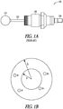
- FIG. 1A is a prior art ball on stick particulate matter sensor.
- the sensor 100 may be a spark-plug-like device having an extended center electrode 120 composed of a stainless steel or other material.
- the electrode 120 and ball 110 may have a thin passivating layer formed on it.
- the sensor 100 may detect charge transients indicative of particulate concentration in the exhaust stream.
- the sensor 100 may be built upon an automotive spark plug 140.
- Ball 110 of sensor 100 may be placed in the path of the exhaust of an engine.
- Ball 110 and electrode 120 may be passivated with a very thin nonconductive coating or layer. This coating or layer accounts for the lack of electrical shorting by the soot layer accumulated by ball 110 and electrode 120 during operation of the engine.
- the passivation material may be composed of silicon nitride (Si 3 N 4 ), ceria and the like.
- the thickness of the passivation layer on ball 110 and electrode 120 may be between 0.001 and 0.100 inch. A nominal thickness may be about 0.01 inch.
- the passivation layer may be achieved with the exposure of the probe to high exhaust gas temperatures or may be coated with such layer via a material added to the engine fuel.
- a ball 110 was placed at the end of a sensor probe similar to electrode 120 to try and induce additional vibration to the sensor 100 and to see if any component of that vibration was due to pressure or velocity variances in the exhaust stream. No additional noise due to vibration was seen, but the signal amplitude increased by about 50% due to the increased surface area. It was determined that the ball-on-stick electrode 110 and 120 structure provides a large surface area at a favored point in the exhaust gas stream. The inventors however have determined that the ball on stick sensor 100 has added costs due to the expense and time of welding ball 110 onto sensor probe 120.
- An embodiment of sensor 100 may be a standard spark plug 140 (such as a Champion TM RJ19LM, though the model is not important) that has the outside electrode removed and has a 4 to 6 inch stainless steel electrode 120 of about 1/8 inch diameter welded to the center electrode 130.
- a stainless steel ball 110 may then be welded to the other end of the electrode 120.
- the extended electrode 129 and ball 110 may be passivated as discussed above with a very thin non-conducting surface layer, so that the ball 110 and electrode 120 will develop an image charge from the exhaust particulates but will not be electrically shorted to the spark plug base 140 or the grounded exhaust pipe.
- the passivating layer may be deposited or grown on the electrode 120 and ball 110.
- FIG. 1B shows a simplified model of the operation of the sensor.
- the sensor operates as a capacitor formed by two concentric spheres.
- the inner sphere has radius a, and the outer sphere has radius b.
- the inner sphere corresponds to the sensor such as ball 110 of FIG. 1 and the outer sphere corresponds to the surrounding exhaust pipe.
- Charges present in the region between the spheres, shown here as individual electron charges, will produce a voltage between the spheres.
- the ball on stick particle sensor 100 of FIG. 1A utilizing the larger mass or ball 110 at the end of electrode 120 has been shown to provide very good results.
- the inventors have determine that the manufacture requirements of welding the ball 110 onto the rod portion of the electrode 120 assembly is complicated.
- Figs. 4-7 show some representative three dimensional structures that can be used, although other, similar, three dimensional structures may be apparent to those skilled in the art.
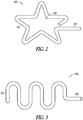
- FIG. 2 is an example of a sensor tip 200 formed by wire bending in two dimensions.
- the electrode 220 is bent into a star shape, such that a mass is primarily located at the end 210 of electrode 220.
- a mass is primarily located at the end 210 of electrode 220.
- the star 230 is flattened means of forging, crimping, or other mechanical operation.
- FIG. 3 is an example of a sensor tip 300 formed by wire bending in two dimensions.
- the electrode 320 of FIG. 3 is bent into a series of bends much in the form of a series of S's. Thereby as in FIG. 2 the end 310 of electrode 320 having a greater surface area.
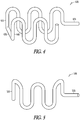
- FIG. 4 is a sensor tip 400 formed by wire bending in three dimensions according to an example embodiment.
- the electrode 420 of FIG. 4 is bent into a series of bends as with FIG. 3 in the form of a series of S's.
- a bend of ninety degrees provides a bridge 430 to a second series of S's 440. This shape provides for a greater volume increasing the effect noted with the ball on a stick.
- FIG. 5 is a sensor tip 500 formed by wire bending in three dimensions according to an example embodiment.
- the electrode 520 is bent in a series of S's in one axis and then bent to form a circle to increase the volume at the end 510 of electrode 520.
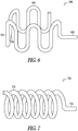
- FIG. 6 is a sensor tip 600 formed by wire bending in three dimensions according to an example embodiment.
- the electrode 620 is bent in a series of S's in one axis and then bent to form a circle to increase the volume at the end 610 of electrode 620.
- a bend of ninety degrees provides a bridge 630 to a second series of S's 640 that are also formed into a circle.
- FIG. 7 is a sensor tip 700 formed by wire bending the sensor end into a helical shape according to an example embodiment.
- the electrode 720 is bent into a helical shape at the end 710.
- each of the sensor tips illustrated in FIG. 2 through 6 may have increase surface area by flattening the rod 220, 320, 420, 520, 620, and 720 of FIGs. 2-7 respectively, by means of forging, crimping, or other mechanical operation.
- the various sensor tips are thus formed in multiple dimension shapes to increase the surface area of the tip at the end of the electrode.
- FIG. 8 is a system 800 incorporating sensors 810, 820 and 830 of an example embodiment.
- Sensor 810 may be installed in an exhaust pipe 818.
- There may be a stainless steel collar (not shown) welded into the exhaust pipe 818.
- the collar may be fabricated with an oversized threaded access so that the sensor 810 could be easily changed with other sensors 810 having different probe styles.
- Additional sensors 820 may be mounted in the exhaust manifold 822 upstream from turbocharger 819.
- Other sensors 830 may be mounted further down stream, for example about 2 meters, in exhaust pipe 818 from the turbocharger 819.
- the additional sensors 820 and 830 may allow one to examine the effects of the turbocharger 819, such as strong mixing, and residence time on a signal from sensor 810. In the long term sites downstream from turbocharger 819 may be good locations because of the reduced risk of damage to the turbocharger 819 in the event of a sensor 810 failure. Signals 825, indicating an amount of particulate matter in the exhaust 823, on the line from sensor 810 may go to a processor and/or controller 826. Processor 826 may be connected to other particulate sensors 820 and 830, engine sensors, and a fuel injection and intake manifold system 827.
- processor 826 may provide control information signals 829 to the fuel injection amount and timing, EGR percent, valve control, and intake manifold system 827 and the like as desired, so as to cause engine 821 to expel a reduced amount of particulate emissions by adjusting fuel mixture, injection timing, percent EGR, valve control, and so forth.
- exhaust 823 may enter turbocharger 819 and cause a turbine 831 to spin and turn a compressor 832 via a shaft 833.
- Compressor 832 may compress incoming air 828 which goes in a more dense condition
- Sensor 810 may put out a reproducible rms signal representing its image charge monitoring of the exhaust 823, which is correlated to exhaust smoke as characterized by the Bosch smoke number. Sensor 810 generally does not degrade due to soot build-up over a long period of time. Also, sensor 810 does not appear to degrade at various temperatures.
- FIG. 9 a system incorporating a sensor of an example embodiment.
- FIG. 9 is one version of a loop for engine control based on the particulate matter of the exhaust emissions.
- Engine 921 may output an exhaust 923 which is sensed by sensor 910 which in turn may output an image charge signal 925 to processor 926 which may include an amplifier 934, a data extractor 935, and an output signal conditioner 936, among other components of the processor.
- Signal 925 may go to a charge amplifier 934 which may output a real-time signal to a data extraction device 935 which may receive a crankshaft angle determination.
- Components 934, 935 and 936 may have other parameter inputs for improving engine control and performance.
- the output from device 935 may include an electronic indication of the particulate matter concentration or concentrations.
- This signal may go to signal conditioning 936 which may, based on other various inputs of engine data (e.g. timing, temperature, percent EGR, valve position, and other engine information) provide engine control voltage signals 929 (for engine timing, percent EGR, valve control, and the like) to the fuel injection and manifold system 927 of engine 921.
- engine data e.g. timing, temperature, percent EGR, valve position, and other engine information
- engine control voltage signals 929 for engine timing, percent EGR, valve control, and the like
- FIG. 10 is a method for making the sensor tips according to an example embodiment.
- the method 1000 takes an insulated device and forms an elongated electrode and then prepares the electrode to provide for a uniform oxidation layer and to formulate the oxidation layer.
- an insulated device is obtained with an elongated electrode.
- the insulated device may be of a shape similar to a spark plug for a car with the center electrode either elongated from the terminal or soldered onto the center rod of the plug.
- the electrode may be formed following the steps, 1007 through 1070.
- Activity 1007 may be to bend the second end of the center electrode to form a enlarged surface area where the electrode will come in contact with the exhaust.
- the rod is rubbed with a pumice.
- the electrodes are mechanically scrubbed and honed to remove any oxide scale that exists on the rods. This will increase the uniformity of the subsequent etching process.
- Activity 1020 may be to hone the electrode with a wet blast using a mixture of water and silica abrasive at 55 pounds per square inch of pressure. A silica size of 7/0 was found to be suitable. This step cleans the electrodes prior to etching.
- Activity 1030 may be to then wash the electrodes in alconox, or other suitable detergent, to prevent contamination of the etch solution.
- Activity 1040 may be to chemically etch the electrodes in a ferric chloride solution to remove inclusions and micro-roughen the surface for improved oxide adhesion.
- Activity 1050 is to rinse the electrodes and then wash the electrodes in an alconox detergent with ultrasonic vibrations to remove any impurities or debris left on the surface. The electrodes are then thoroughly rinsed to remove any chemical contamination. The electrodes are then dipped in acetone and blown dry with filtered nitrogen to minimize staining.
- Activity 1060 may be to place the electrodes on quartz boats and heat the electrodes to induce oxidation.
- the electrodes are oxidized at elevated temperatures in air to form aluminum oxide (alumina/Al 2 O 3 ) scale.
- the aluminum within the alloy supplies the metal for the alumina formation.
- the alumina provides oxidation protection and electrical insulation.
- One embodiment is to use an oxidation temperature of 1200°C and for 14 hours.
- the alumina oxide will form at lower temperatures and shorter times, but higher temperatures form a more dense coating and longer times form thicker coatings which have superior insulation properties.
- the inventors have noted that these alloys typically have melting points between 1350°C and 1450°C and temperatures above 1200°C typically result in the metal sagging and shape deformation.
- Activity 1070 may be for the electrodes to be rinsed in flowing deionized water for 10 minutes and blown dry with nitrogen.
- super alloys have a native oxide with insulating properties suitable for construction of particulate matter sensor electrodes.
- Super alloys contain aluminum as an alloying addition. When heated in air at high temperatures, the aluminum forms a surface dielectric layer. Since the aluminum has a high diffusivity in the alloys, this surface oxide can be thick. For example, fecralloy, oxidized at 1200 °C for fourteen hours, was found to have a breakdown voltage of 280.3 ⁇ 67.5 volts and an insulation resistance of 41.6 ⁇ 14.9 mega ohms when measured at 850 °C.
- Common iron-based super alloys include fecralloy (Resistalloy International), Kanthal-AF (Kanthal/Sandvik Corp.), Kanthal-A1 (Kanthal/Sandvik Corp.), Aluchrome-O (Thyssen-Krupp VDM), Alkrothal-14 ((Kanthal/Sandvik Corp.), and Haynes 214 (Haynes International).
- a representative nickel-based super alloy is Mar-M-247 (Martin Marietta Materials). The inventors have determined that super alloys oxidized at 1200 °C for fourteen hours were found to have electrical insulating properties at 500 °C. These properties included dielectric breakdown strength greater than 25 volts, and insulation resistance greater than 1 megohm.
- Oxide thickness in this range is sufficient for particulate matter sensor electrodes operating at high temperatures, although oxide thickness of about one micrometer may be suitable for some applications, especially those at lower temperature. Greater oxide thickness in the range of 5-20 micrometers may also be suitable, but oxide thickness greater than about twenty micrometers should be avoided, since the thermal stress at the oxide-alloy interface may promote spallation of the insulating oxide. The maximum oxide thickness for reduction or elimination of oxide spallation will depend on the particular alloy selected, the intended application, and geometry of the electrode.
Landscapes
- Chemical & Material Sciences (AREA)
- Engineering & Computer Science (AREA)
- General Physics & Mathematics (AREA)
- Immunology (AREA)
- Life Sciences & Earth Sciences (AREA)
- Analytical Chemistry (AREA)
- Biochemistry (AREA)
- General Health & Medical Sciences (AREA)
- Physics & Mathematics (AREA)
- Health & Medical Sciences (AREA)
- Pathology (AREA)
- Dispersion Chemistry (AREA)
- Combustion & Propulsion (AREA)
- Mechanical Engineering (AREA)
- General Engineering & Computer Science (AREA)
- Investigating Or Analyzing Materials By The Use Of Electric Means (AREA)
- Ignition Installations For Internal Combustion Engines (AREA)
Claims (10)
- Partikeldetektor (810, 820, 830), umfassend:eine isolierte Vorrichtung (810, 820, 830, 910); undeine lang gestreckte Zentralelektrode (400, 500, 600, 700), die ein erstes Ende (420, 520, 620, 720) und ein zweites Ende (410, 510, 610, 710) aufweist, wobei das erste Ende der Zentralelektrode die isolierte Vorrichtung durchquert und mit einer Klemme verbunden wird und wobei das zweite Ende der Zentralelektrode gebogen ist, dadurch gekennzeichnet, dass das zweite Ende der Zentralelektrode ohne Schweißen in eine dreidimensionale Form (410, 510, 610, 710) gebogen ist, wodurch eine längere Gesamtlänge des zweiten Endes der Elektrode in einem speziellen Bereich im Vergleich zu einem nicht dreidimensional geformten zweiten Ende der Elektrode bereitgestellt wird, und wodurch ein vergrößerter Oberflächenbereich des zweiten Endes in dem speziellen Bereich der Zentralelektrode bereitgestellt wird.
- Detektor (810, 820, 830) nach Anspruch 1, wobei das zweite Ende (410, 510, 610, 710) der Elektrode in einer S-Form gebildet ist, die eine Biegung zu einer zweiten Reihe von Biegungen in einer S-Form (400, 600) oder einer Spirale (700) aufweist.
- Detektor (810, 820, 830) nach Anspruch 1 oder 2, wobei das zweite Ende der Elektrode abgeflacht ist (430, 630).
- Detektor (810, 820, 830) nach Anspruch 1, 2 oder 3, wobei:die Zentralelektrode (400, 500, 600, 700) eine Länge zwischen 0,25 Zoll und 12 Zoll aufweist; unddie Zentralelektrode (400, 500, 600, 700) eine Dicke zwischen 1/32 Zoll und 3/8 Zoll aufweist.
- Detektor (810, 820, 830) nach Anspruch 1, 2, 3 oder 4, wobei:die isolierte Vorrichtung eine Klemme (810, 910) aufweist, die mit dem ersten Ende (420, 520, 620, 720) der Zentralelektrode (400, 500, 600, 700) verbunden ist; unddie Klemme (810, 910) mit einem Verstärker (934) verbunden ist, der einen Ausgang aufweist, der eine Partikelkonzentration in einer Nähe des zweiten Endes (410, 510, 610, 710) der Elektrode (400, 500, 600, 700) anzeigen kann.
- Detektor (810, 820, 830) nach Anspruch 5, wobei das zweite Ende (410, 510, 610, 710) der Zentralelektrode in einem Abschnitt eines Verbrennungsmechanismus (800, 818, 823) angebracht ist.
- Detektor (810, 820, 830) nach Anspruch 1, wobei die Elektrode aus einer Eisen-Chrom-Legierung oder einer Aluminium enthaltenden Legierung gebildet ist.
- Verfahren zum Herstellen eines Partikeldetektors (810, 820, 830), umfassend:Erhalten einer isolierten Vorrichtung, die eine lang gestreckte Zentralelektrode (1003, 400, 500, 600, 700) aufweist, die ein erstes Ende (420, 520, 620, 720) und ein zweites Ende (410, 510, 610, 710) aufweist, wobei das erste Ende der Zentralelektrode die isolierte Vorrichtung durchquert und mit einer Klemme verbunden wird, undBiegen des zweiten Endes (410, 510, 610, 710) der Zentralelektrode, dadurch gekennzeichnet, dass das zweite Ende ohne Schweißen in eine dreidimensionale Form gebogen wird, wodurch eine längere Gesamtlänge des zweiten Endes (410, 510, 610, 710) der Elektrode in einem speziellen Bereich (230) im Vergleich zu einem nicht dreidimensionalen zweiten Ende der Elektrode bereitgestellt wird, und wodurch ein größerer Oberflächenbereich des zweiten Endes in dem speziellen Bereich der Zentralelektrode (1007) gebildet wird.
- Verfahren nach Anspruch 8, umfassend:Aufheizen der Zentralelektrode (400, 500, 600, 700), um eine Oxidation herbeizuführen (1060).
- Verfahren nach Anspruch 9, umfassend:Reiben der Elektrode (400, 500, 600, 700) mit einem Bimsstein (1010);Honen der Elektrode mit einer Mischung aus einem Siliciumdioxidschleifmittel und Wasser (1020); und Reinigen der Elektrode in einem Reinigungsmittel (1030).
Applications Claiming Priority (1)
| Application Number | Priority Date | Filing Date | Title |
|---|---|---|---|
| US12/020,950 US7966862B2 (en) | 2008-01-28 | 2008-01-28 | Electrode structure for particulate matter sensor |
Publications (3)
| Publication Number | Publication Date |
|---|---|
| EP2090879A2 EP2090879A2 (de) | 2009-08-19 |
| EP2090879A3 EP2090879A3 (de) | 2013-10-16 |
| EP2090879B1 true EP2090879B1 (de) | 2017-08-02 |
Family
ID=40428244
Family Applications (1)
| Application Number | Title | Priority Date | Filing Date |
|---|---|---|---|
| EP09151040.4A Active EP2090879B1 (de) | 2008-01-28 | 2009-01-21 | Elektrodenstruktur für einen Partikelsensor |
Country Status (2)
| Country | Link |
|---|---|
| US (1) | US7966862B2 (de) |
| EP (1) | EP2090879B1 (de) |
Families Citing this family (15)
| Publication number | Priority date | Publication date | Assignee | Title |
|---|---|---|---|---|
| US7928634B2 (en) * | 2008-04-22 | 2011-04-19 | Honeywell International Inc. | System and method for providing a piezoelectric electromagnetic hybrid vibrating energy harvester |
| WO2009140677A2 (en) * | 2008-05-16 | 2009-11-19 | Honeywell International Inc. | Particulate matter sensor |
| US8047054B2 (en) * | 2008-07-24 | 2011-11-01 | Fram Group Ip Llc | Particulate matter sensor |
| DE102010029575A1 (de) | 2010-06-01 | 2011-12-01 | Robert Bosch Gmbh | Verfahren und Partikelsensor zum Erfassen von Partikeln in einem Abgasstrom |
| DE102010038153B3 (de) * | 2010-10-13 | 2012-03-08 | Ford Global Technologies, Llc. | Partikelsensor, Abgassystem und Verfahren zum Schutz von Komponenten eines turbogeladenen Motors mit Abgasrückführung |
| KR101934887B1 (ko) * | 2011-06-22 | 2019-01-04 | 코닌클리케 필립스 엔.브이. | 전극의 공기 이온화부를 세척하기 위한 세척 디바이스 |
| KR101305198B1 (ko) * | 2011-12-09 | 2013-09-26 | 현대자동차주식회사 | 입자상물질 센서유닛 |
| US8823401B2 (en) * | 2012-03-30 | 2014-09-02 | Delphi Technologies, Inc. | Particulate matter sensor with two pairs of sensing electrodes and methods of using same |
| JP6228018B2 (ja) | 2014-01-10 | 2017-11-08 | 株式会社Soken | 粒子状物質検出素子、粒子状物質検出センサ並びに粒子状物質検出素子の製造方法 |
| EP3187863B1 (de) * | 2014-08-29 | 2019-08-07 | Kyocera Corporation | Sensorsubstrat, sensorsubstrat mit einer leitung und sensorvorrichtung |
| JP6654350B2 (ja) * | 2015-02-18 | 2020-02-26 | 三菱航空機株式会社 | 配管構造および航空機 |
| KR20160149898A (ko) | 2015-06-19 | 2016-12-28 | 현대자동차주식회사 | 입자상 물질 센서 |
| JP6918806B2 (ja) * | 2016-01-08 | 2021-08-11 | ティーエスアイ インコーポレイテッド | ウェアラブル・マスク・フィット・モニタ |
| US10018098B2 (en) | 2016-04-14 | 2018-07-10 | Ford Global Technologies, Llc | Method and system for exhaust particulate matter sensing |
| CN112179284B (zh) * | 2020-09-25 | 2021-10-15 | 贵州百事通建筑安装工程有限公司 | 一种钢结构焊接球节点和螺栓球节点的承载力检验方法 |
Family Cites Families (45)
| Publication number | Priority date | Publication date | Assignee | Title |
|---|---|---|---|---|
| US3869703A (en) * | 1970-03-16 | 1975-03-04 | Philips Corp | Semiconductor device having an improved supply lead support |
| US4021326A (en) | 1972-06-02 | 1977-05-03 | Robert Bosch G.M.B.H. | Electro-chemical sensor |
| DE2700807A1 (de) | 1977-01-11 | 1978-07-13 | Bosch Gmbh Robert | Festelektrolytrohr fuer einen messfuehler zur bestimmung des sauerstoffgehaltes in abgasen und verfahren zur herstellung desselben |
| DE2836002C2 (de) | 1978-08-17 | 1986-09-11 | Robert Bosch Gmbh, 7000 Stuttgart | Sensor zur Überwachung der Rußfreiheit von Abgasen |
| DE2913866C2 (de) | 1979-04-06 | 1987-03-12 | Robert Bosch Gmbh, 7000 Stuttgart | Meßfühler für die Bestimmung von Bestandteilen in strömenden Gasen |
| DE2942494A1 (de) | 1979-10-20 | 1981-04-30 | Bosch Gmbh Robert | Beheizbarer messfuehler fuer bestandteile von gasen, insbesondere in abgasen von brennkraftmaschinen |
| US4656832A (en) | 1982-09-30 | 1987-04-14 | Nippondenso Co., Ltd. | Detector for particulate density and filter with detector for particulate density |
| US4485794A (en) | 1982-10-04 | 1984-12-04 | United Technologies Diesel Systems, Inc. | Method and apparatus for controlling diesel engine exhaust gas recirculation partly as a function of exhaust particulate level |
| US5271821A (en) | 1988-03-03 | 1993-12-21 | Ngk Insulators, Ltd. | Oxygen sensor and method of producing the same |
| FR2640955B1 (de) * | 1988-12-26 | 1991-11-29 | Taillet Joseph | |
| DE69026353T2 (de) * | 1989-12-19 | 1996-11-14 | Matsushita Electric Ind Co Ltd | Feldemissionsvorrichtung und Verfahren zur Herstellung derselben |
| US5076237A (en) | 1990-01-11 | 1991-12-31 | Barrack Technology Limited | Means and method for measuring and controlling smoke from an internal combustion engine |
| KR950004615B1 (ko) | 1990-09-27 | 1995-05-03 | 미쓰비시덴키 가부시키가이샤 | 내연기관용 점화플러그 |
| GB2277154B (en) | 1993-04-06 | 1997-06-25 | Pollution Control & Measuremen | Method and apparatus for detecting particles in a flow |
| WO1995018777A1 (de) | 1994-01-05 | 1995-07-13 | Roth-Technik Gmbh & Co. Forschung Für Automobil- Und Umwelttechnik | Elektrisch leitende verbindung |
| US5898257A (en) | 1995-08-25 | 1999-04-27 | Sequerra; Richard Isaac | Combustion initiators employing reduced work function stainless steel electrodes |
| DE19536705A1 (de) * | 1995-09-30 | 1997-04-03 | Guenther Prof Dr Ing Hauser | Partikel-Meßverfahren und Vorrichtung |
| JP3333678B2 (ja) | 1996-01-05 | 2002-10-15 | 株式会社日立製作所 | ガス成分センサ及び触媒診断装置 |
| US5681986A (en) | 1996-05-07 | 1997-10-28 | Auburn International, Inc. | Acoustic sensing |
| JP3813708B2 (ja) | 1996-09-12 | 2006-08-23 | 日本特殊陶業株式会社 | スパークプラグの製造方法 |
| SE513432C2 (sv) | 1997-12-01 | 2000-09-11 | Volvo Ab | Förfarande för att mäta partikelhalten i avgaserna hos en förbränningsmotor |
| US6583539B1 (en) | 1999-08-23 | 2003-06-24 | Antonio Lopez Zamora | Spark plug with center electrode and surrounding ground electrode |
| JP2001073918A (ja) | 1999-09-02 | 2001-03-21 | Ngk Spark Plug Co Ltd | くすぶり検出方法 |
| DE19959871A1 (de) | 1999-12-10 | 2001-06-28 | Heraeus Electro Nite Int | Sensor und Verfahren zur Ermittlung von Ruß-Konzentrationen |
| DE19959870A1 (de) | 1999-12-10 | 2001-06-21 | Heraeus Electro Nite Int | Meßanordnung und Verfahren zur Überwachung der Funktionsfähigkeit eines Rußfilters |
| DE10052005C2 (de) | 2000-10-20 | 2002-11-21 | Bosch Gmbh Robert | Meßfühler für Gase |
| US6601464B1 (en) | 2000-10-20 | 2003-08-05 | John P. Downing, Jr. | Particle momentum sensor |
| DE10124907A1 (de) | 2001-05-22 | 2002-11-28 | Bosch Gmbh Robert | Elektrodenanordnung |
| JP2003107033A (ja) | 2001-07-27 | 2003-04-09 | Denso Corp | ガスセンサ |
| US7010356B2 (en) * | 2001-10-31 | 2006-03-07 | London Health Sciences Centre Research Inc. | Multichannel electrode and methods of using same |
| US6639671B1 (en) * | 2002-03-01 | 2003-10-28 | Msp Corporation | Wide-range particle counter |
| US6634210B1 (en) | 2002-04-17 | 2003-10-21 | Delphi Technologies, Inc. | Particulate sensor system |
| US7275415B2 (en) * | 2003-12-31 | 2007-10-02 | Honeywell International Inc. | Particulate-based flow sensor |
| US6971258B2 (en) * | 2003-12-31 | 2005-12-06 | Honeywell International Inc. | Particulate matter sensor |
| US7328577B2 (en) | 2004-12-29 | 2008-02-12 | Honeywell International Inc. | Multivariable control for an engine |
| US7389773B2 (en) | 2005-08-18 | 2008-06-24 | Honeywell International Inc. | Emissions sensors for fuel control in engines |
| US7155334B1 (en) | 2005-09-29 | 2006-12-26 | Honeywell International Inc. | Use of sensors in a state observer for a diesel engine |
| US7765792B2 (en) * | 2005-10-21 | 2010-08-03 | Honeywell International Inc. | System for particulate matter sensor signal processing |
| US7628007B2 (en) | 2005-12-21 | 2009-12-08 | Honeywell International Inc. | Onboard diagnostics for anomalous cylinder behavior |
| US7447587B2 (en) | 2005-12-21 | 2008-11-04 | Honeywell International Inc. | Cylinder to cylinder variation control |
| US20080265870A1 (en) | 2007-04-27 | 2008-10-30 | Nair Balakrishnan G | Particulate Matter Sensor |
| US7564043B2 (en) * | 2007-05-24 | 2009-07-21 | Hamamatsu Photonics K.K. | MCP unit, MCP detector and time of flight mass spectrometer |
| US8080427B2 (en) | 2007-07-31 | 2011-12-20 | Caterpillar Inc. | Particle sensor |
| US20090056416A1 (en) | 2007-08-30 | 2009-03-05 | Nair Balakrishnan G | Ceramic Particulate Matter Sensor With Low Electrical Leakage |
| US7900500B2 (en) | 2007-11-05 | 2011-03-08 | Honeywell International Inc. | Particulate matter sensor electrodes with embedded self-calibrator, and methods using same |
-
2008
- 2008-01-28 US US12/020,950 patent/US7966862B2/en active Active
-
2009
- 2009-01-21 EP EP09151040.4A patent/EP2090879B1/de active Active
Non-Patent Citations (1)
| Title |
|---|
| None * |
Also Published As
| Publication number | Publication date |
|---|---|
| US7966862B2 (en) | 2011-06-28 |
| EP2090879A3 (de) | 2013-10-16 |
| US20090188300A1 (en) | 2009-07-30 |
| EP2090879A2 (de) | 2009-08-19 |
Similar Documents
| Publication | Publication Date | Title |
|---|---|---|
| EP2090879B1 (de) | Elektrodenstruktur für einen Partikelsensor | |
| EP1706722B1 (de) | Sensor für partikuläre stoffe | |
| JP6600704B2 (ja) | 煤センサシステム | |
| US8091408B2 (en) | Procedure for operating a collecting particle sensor and device for implementing this procedure | |
| CN105723205B (zh) | 用于运行颗粒传感器的方法和装置 | |
| US9377425B2 (en) | Method and device for regenerating a particle sensor | |
| US20130090866A1 (en) | Diagnostic method for a soot sensor | |
| EP2840388A1 (de) | Gassensor | |
| US20070137177A1 (en) | Onboard Diagnostics for Anomalous Cylinder Behavior | |
| WO2007050384A2 (en) | System for particulate matter sensor signal processing | |
| US20110156727A1 (en) | Soot Sensor | |
| CN107208545A (zh) | 旋转机械的叶轮、压缩机、增压器以及旋转机械的叶轮的制造方法 | |
| CN107631966A (zh) | 用于排气微粒物质感测的方法和系统 | |
| CN107300518B (zh) | 用于排气微粒物质感测的方法和系统 | |
| CN105298608A (zh) | 一种新型外置式车用柴油机颗粒物排放诊断方法及装置 | |
| US20080034839A1 (en) | Method and Device for Monitoring Particle Concentration in Gas Stream | |
| DE19806110A1 (de) | Verfahren zur Ermittlung der Abgastemperatur und der Luft/Kraftstoff-Verhältniszahl Lambda und Sensoranordnung zur Durchführung des Verfahrens | |
| Hoepfner et al. | PM sensor based on-board diagnosis of particulate filter efficiency | |
| US6637254B2 (en) | Sensor element having a protective device | |
| CN107179266A (zh) | 基于obd的柴油发动机颗粒物排放快速诊断装置与方法 | |
| Pfau et al. | Measurement of Sub-23 nm particulate emissions from GDI engines: A comparison of processing methods | |
| JP4669508B2 (ja) | 吸湿性コーティングが施された保護装置を備えるガスプローブ | |
| US11422081B2 (en) | Sensor for use in an exhaust gas stream of an internal combustion engine | |
| KR101860455B1 (ko) | Pm 센서 | |
| JP2010210537A (ja) | 粒子状物質検出装置固定用管状構造体 |
Legal Events
| Date | Code | Title | Description |
|---|---|---|---|
| PUAI | Public reference made under article 153(3) epc to a published international application that has entered the european phase |
Free format text: ORIGINAL CODE: 0009012 |
|
| 17P | Request for examination filed |
Effective date: 20090121 |
|
| AK | Designated contracting states |
Kind code of ref document: A2 Designated state(s): AT BE BG CH CY CZ DE DK EE ES FI FR GB GR HR HU IE IS IT LI LT LU LV MC MK MT NL NO PL PT RO SE SI SK TR |
|
| AX | Request for extension of the european patent |
Extension state: AL BA RS |
|
| PUAL | Search report despatched |
Free format text: ORIGINAL CODE: 0009013 |
|
| AK | Designated contracting states |
Kind code of ref document: A3 Designated state(s): AT BE BG CH CY CZ DE DK EE ES FI FR GB GR HR HU IE IS IT LI LT LU LV MC MK MT NL NO PL PT RO SE SI SK TR |
|
| AX | Request for extension of the european patent |
Extension state: AL BA RS |
|
| RIC1 | Information provided on ipc code assigned before grant |
Ipc: G01N 15/06 20060101AFI20130906BHEP |
|
| AKX | Designation fees paid |
Designated state(s): DE |
|
| 17Q | First examination report despatched |
Effective date: 20141218 |
|
| RAP1 | Party data changed (applicant data changed or rights of an application transferred) |
Owner name: HONEYWELL INTERNATIONAL INC. |
|
| REG | Reference to a national code |
Ref country code: DE Ref legal event code: R079 Ref document number: 602009047446 Country of ref document: DE Free format text: PREVIOUS MAIN CLASS: G01N0015060000 Ipc: F02D0041140000 |
|
| GRAP | Despatch of communication of intention to grant a patent |
Free format text: ORIGINAL CODE: EPIDOSNIGR1 |
|
| RIC1 | Information provided on ipc code assigned before grant |
Ipc: F02D 41/14 20060101AFI20170214BHEP Ipc: G01N 15/06 20060101ALI20170214BHEP Ipc: F01N 9/00 20060101ALN20170214BHEP |
|
| INTG | Intention to grant announced |
Effective date: 20170317 |
|
| GRAS | Grant fee paid |
Free format text: ORIGINAL CODE: EPIDOSNIGR3 |
|
| GRAA | (expected) grant |
Free format text: ORIGINAL CODE: 0009210 |
|
| AK | Designated contracting states |
Kind code of ref document: B1 Designated state(s): DE |
|
| REG | Reference to a national code |
Ref country code: DE Ref legal event code: R096 Ref document number: 602009047446 Country of ref document: DE |
|
| REG | Reference to a national code |
Ref country code: DE Ref legal event code: R097 Ref document number: 602009047446 Country of ref document: DE |
|
| PLBE | No opposition filed within time limit |
Free format text: ORIGINAL CODE: 0009261 |
|
| STAA | Information on the status of an ep patent application or granted ep patent |
Free format text: STATUS: NO OPPOSITION FILED WITHIN TIME LIMIT |
|
| 26N | No opposition filed |
Effective date: 20180503 |
|
| PGFP | Annual fee paid to national office [announced via postgrant information from national office to epo] |
Ref country code: DE Payment date: 20260127 Year of fee payment: 18 |