EP2090475A1 - In zwei Stufen arbeitende Halterung mit großem Rückhaltevermögen - Google Patents
In zwei Stufen arbeitende Halterung mit großem Rückhaltevermögen Download PDFInfo
- Publication number
- EP2090475A1 EP2090475A1 EP09002064A EP09002064A EP2090475A1 EP 2090475 A1 EP2090475 A1 EP 2090475A1 EP 09002064 A EP09002064 A EP 09002064A EP 09002064 A EP09002064 A EP 09002064A EP 2090475 A1 EP2090475 A1 EP 2090475A1
- Authority
- EP
- European Patent Office
- Prior art keywords
- fastener
- vehicle
- dog
- house
- engagement
- Prior art date
- Legal status (The legal status is an assumption and is not a legal conclusion. Google has not performed a legal analysis and makes no representation as to the accuracy of the status listed.)
- Granted
Links
- 230000014759 maintenance of location Effects 0.000 title description 4
- 238000006073 displacement reaction Methods 0.000 claims description 18
- 238000000034 method Methods 0.000 claims description 5
- 238000000465 moulding Methods 0.000 claims description 2
- 239000000463 material Substances 0.000 description 10
- 238000009434 installation Methods 0.000 description 6
- 229910000639 Spring steel Inorganic materials 0.000 description 5
- 230000000712 assembly Effects 0.000 description 3
- 238000000429 assembly Methods 0.000 description 3
- 239000002184 metal Substances 0.000 description 3
- 238000005452 bending Methods 0.000 description 2
- 238000003780 insertion Methods 0.000 description 2
- 230000037431 insertion Effects 0.000 description 2
- 230000000717 retained effect Effects 0.000 description 2
- 238000000926 separation method Methods 0.000 description 2
- 230000004913 activation Effects 0.000 description 1
- 230000003247 decreasing effect Effects 0.000 description 1
- 239000007769 metal material Substances 0.000 description 1
- 238000004080 punching Methods 0.000 description 1
- 230000003068 static effect Effects 0.000 description 1
Images


Classifications
-
- B—PERFORMING OPERATIONS; TRANSPORTING
- B60—VEHICLES IN GENERAL
- B60R—VEHICLES, VEHICLE FITTINGS, OR VEHICLE PARTS, NOT OTHERWISE PROVIDED FOR
- B60R21/00—Arrangements or fittings on vehicles for protecting or preventing injuries to occupants or pedestrians in case of accidents or other traffic risks
- B60R21/02—Occupant safety arrangements or fittings, e.g. crash pads
- B60R21/16—Inflatable occupant restraints or confinements designed to inflate upon impact or impending impact, e.g. air bags
- B60R21/20—Arrangements for storing inflatable members in their non-use or deflated condition; Arrangement or mounting of air bag modules or components
- B60R21/215—Arrangements for storing inflatable members in their non-use or deflated condition; Arrangement or mounting of air bag modules or components characterised by the covers for the inflatable member
-
- B—PERFORMING OPERATIONS; TRANSPORTING
- B60—VEHICLES IN GENERAL
- B60R—VEHICLES, VEHICLE FITTINGS, OR VEHICLE PARTS, NOT OTHERWISE PROVIDED FOR
- B60R13/00—Elements for body-finishing, identifying, or decorating; Arrangements or adaptations for advertising purposes
- B60R13/02—Internal Trim mouldings ; Internal Ledges; Wall liners for passenger compartments; Roof liners
- B60R13/0206—Arrangements of fasteners and clips specially adapted for attaching inner vehicle liners or mouldings
-
- F—MECHANICAL ENGINEERING; LIGHTING; HEATING; WEAPONS; BLASTING
- F16—ENGINEERING ELEMENTS AND UNITS; GENERAL MEASURES FOR PRODUCING AND MAINTAINING EFFECTIVE FUNCTIONING OF MACHINES OR INSTALLATIONS; THERMAL INSULATION IN GENERAL
- F16B—DEVICES FOR FASTENING OR SECURING CONSTRUCTIONAL ELEMENTS OR MACHINE PARTS TOGETHER, e.g. NAILS, BOLTS, CIRCLIPS, CLAMPS, CLIPS OR WEDGES; JOINTS OR JOINTING
- F16B21/00—Means for preventing relative axial movement of a pin, spigot, shaft or the like and a member surrounding it; Stud-and-socket releasable fastenings
- F16B21/06—Releasable fastening devices with snap-action
- F16B21/07—Releasable fastening devices with snap-action in which the socket has a resilient part
- F16B21/073—Releasable fastening devices with snap-action in which the socket has a resilient part the socket having a resilient part on its inside
- F16B21/075—Releasable fastening devices with snap-action in which the socket has a resilient part the socket having a resilient part on its inside the socket having resilient parts on its inside and outside
-
- F—MECHANICAL ENGINEERING; LIGHTING; HEATING; WEAPONS; BLASTING
- F16—ENGINEERING ELEMENTS AND UNITS; GENERAL MEASURES FOR PRODUCING AND MAINTAINING EFFECTIVE FUNCTIONING OF MACHINES OR INSTALLATIONS; THERMAL INSULATION IN GENERAL
- F16B—DEVICES FOR FASTENING OR SECURING CONSTRUCTIONAL ELEMENTS OR MACHINE PARTS TOGETHER, e.g. NAILS, BOLTS, CIRCLIPS, CLAMPS, CLIPS OR WEDGES; JOINTS OR JOINTING
- F16B21/00—Means for preventing relative axial movement of a pin, spigot, shaft or the like and a member surrounding it; Stud-and-socket releasable fastenings
- F16B21/06—Releasable fastening devices with snap-action
- F16B21/08—Releasable fastening devices with snap-action in which the stud, pin, or spigot has a resilient part
- F16B21/084—Releasable fastening devices with snap-action in which the stud, pin, or spigot has a resilient part with a series of flexible ribs or fins extending laterally from the shank of the stud, pin or spigot, said ribs or fins deforming predominantly in a direction parallel to the direction of insertion of the shank
-
- F—MECHANICAL ENGINEERING; LIGHTING; HEATING; WEAPONS; BLASTING
- F16—ENGINEERING ELEMENTS AND UNITS; GENERAL MEASURES FOR PRODUCING AND MAINTAINING EFFECTIVE FUNCTIONING OF MACHINES OR INSTALLATIONS; THERMAL INSULATION IN GENERAL
- F16B—DEVICES FOR FASTENING OR SECURING CONSTRUCTIONAL ELEMENTS OR MACHINE PARTS TOGETHER, e.g. NAILS, BOLTS, CIRCLIPS, CLAMPS, CLIPS OR WEDGES; JOINTS OR JOINTING
- F16B21/00—Means for preventing relative axial movement of a pin, spigot, shaft or the like and a member surrounding it; Stud-and-socket releasable fastenings
- F16B21/06—Releasable fastening devices with snap-action
- F16B21/08—Releasable fastening devices with snap-action in which the stud, pin, or spigot has a resilient part
- F16B21/086—Releasable fastening devices with snap-action in which the stud, pin, or spigot has a resilient part the shank of the stud, pin or spigot having elevations, ribs, fins or prongs intended for deformation or tilting predominantly in a direction perpendicular to the direction of insertion
-
- F—MECHANICAL ENGINEERING; LIGHTING; HEATING; WEAPONS; BLASTING
- F16—ENGINEERING ELEMENTS AND UNITS; GENERAL MEASURES FOR PRODUCING AND MAINTAINING EFFECTIVE FUNCTIONING OF MACHINES OR INSTALLATIONS; THERMAL INSULATION IN GENERAL
- F16B—DEVICES FOR FASTENING OR SECURING CONSTRUCTIONAL ELEMENTS OR MACHINE PARTS TOGETHER, e.g. NAILS, BOLTS, CIRCLIPS, CLAMPS, CLIPS OR WEDGES; JOINTS OR JOINTING
- F16B21/00—Means for preventing relative axial movement of a pin, spigot, shaft or the like and a member surrounding it; Stud-and-socket releasable fastenings
- F16B21/09—Releasable fastening devices with a stud engaging a keyhole slot
-
- Y—GENERAL TAGGING OF NEW TECHNOLOGICAL DEVELOPMENTS; GENERAL TAGGING OF CROSS-SECTIONAL TECHNOLOGIES SPANNING OVER SEVERAL SECTIONS OF THE IPC; TECHNICAL SUBJECTS COVERED BY FORMER USPC CROSS-REFERENCE ART COLLECTIONS [XRACs] AND DIGESTS
- Y10—TECHNICAL SUBJECTS COVERED BY FORMER USPC
- Y10T—TECHNICAL SUBJECTS COVERED BY FORMER US CLASSIFICATION
- Y10T24/00—Buckles, buttons, clasps, etc.
- Y10T24/30—Trim molding fastener
- Y10T24/304—Resilient metal type
-
- Y—GENERAL TAGGING OF NEW TECHNOLOGICAL DEVELOPMENTS; GENERAL TAGGING OF CROSS-SECTIONAL TECHNOLOGIES SPANNING OVER SEVERAL SECTIONS OF THE IPC; TECHNICAL SUBJECTS COVERED BY FORMER USPC CROSS-REFERENCE ART COLLECTIONS [XRACs] AND DIGESTS
- Y10—TECHNICAL SUBJECTS COVERED BY FORMER USPC
- Y10T—TECHNICAL SUBJECTS COVERED BY FORMER US CLASSIFICATION
- Y10T24/00—Buckles, buttons, clasps, etc.
- Y10T24/44—Clasp, clip, support-clamp, or required component thereof
- Y10T24/44017—Clasp, clip, support-clamp, or required component thereof with specific mounting means for attaching to rigid or semirigid supporting structure or structure-to-be-secured
- Y10T24/44026—Clasp, clip, support-clamp, or required component thereof with specific mounting means for attaching to rigid or semirigid supporting structure or structure-to-be-secured for cooperating with aperture in supporting structure or structure-to-be-secured
Definitions
- the present disclosure relates to automobile fastener clips used to join components to a vehicle body.
- fasteners are used to join trim or panel members to sections or metal body portions of the automobile.
- the requirements for these fasteners are that they be insertable into apertures of the automobile and meet requirements to both retain the component as well as provide a minimum pullout retention force such that the component is retained under given load conditions but can be removed without damaging the component.
- Common fastener designs include directly opposed flexible wings which deflect inwardly upon insertion of the fastener and expand by spring force to hold the fastener within an aperture such as a slot in the automobile.
- a drawback of commonly used fasteners occurs for certain applications, including fasteners used to mount trim or instrument panels, or for trim components which cover air bags.
- fasteners used to mount trim or instrument panels, or for trim components which cover air bags.
- deployment of the air bag often displaces the trim component, however, it is undesirable for the trim component to freely disassociate from the body portion of the automobile.
- fasteners have been created having two-part assemblies, with one part connected to the vehicle body and the second part connected to the trim component or panel member.
- fastener designs commonly include a tether which allows the trim or panel component to displace while preventing disassociation from the first part and therefore from the vehicle body.
- a drawback of these fastener designs is the tether only loosely retains the trim or panel member which can still result in realignment problems, or inadvertent disconnection of electrical connectors, or the like.
- a fastener system for use with an air bag has a fastener including a rounded base having a flat portion, and first and second arms oriented transverse to the flat portions.
- a first set of vehicle panel engagement devices is connected to the fastener proximate to the rounded base.
- a second set of vehicle panel engagement devices is connected to the fastener spatially separated from both the first set of vehicle panel engagement devices and the rounded base.
- a vehicle component has a dog-house homogenously connected thereto. The rounded base is slidably received within and engaged with the dog-house to releasably connect the fastener to the vehicle component.
- the vehicle component is adapted to be displaceable upon deployment of an air bag.
- a fastener assembly includes a first member having first and second arms each including first and second elongated slots.
- a second member is slidingly engaged with the first member, the second member having first and second body portions each including first and second tabs extending toward an opposite one of the first and second body portions.
- a plurality of dimples are created on each of the first and second body portions.
- the plurality of dimples of the first body portion extend into the first and second elongated slots of the first arm in a first engaged position of the first and second members, and the plurality of dimples of the second body portion extend into the first and second elongated slots of the second arm in the first engaged position.
- the first and second tabs of the first body portion are slidingly positioned within the first and second elongated slots of the first arm, and the first and second tabs of the second body portion are slidingly positioned within the first and second elongated slots of the second arm.
- a telescoped second engaged position of the fastener assembly has the first and second tabs of the first body portion each in contact with an end wall of the first and second elongated slots of the first arm, and the first and second tabs of the second body portion each in contact with an end wall of the first and second elongated slots of the second arm.
- the telescoped second position also has the plurality of dimples of each of the first and second body portions displaced out of the first and second elongated slots of both the first and second members.
- a fastener system includes a first member having a rounded base having a flat portion and first and second arms oriented transverse to the flat portion.
- the first and second arms each include first and second elongated slots.
- a second member is slidingly engaged with the first member.
- the second member has first and second body portions each including first and second tabs extending toward an opposite one of the first and second body portions. Each of the first and second tabs are slidingly received in one of the first or second slots allowing the second member to slide in a first direction away from the rounded base.
- a dog-house is homogenously connected to a polymeric member. The dog-house receives and engages the rounded base in a second direction transverse to the first direction.
- Figure 1 is front perspective view of a fastener assembly for a two stage, telescoping high retention fastener of the present disclosure
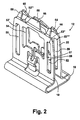
- Figure 2 is front perspective view of a first member of the fastener assembly of Figure 1 ;
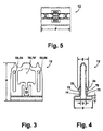
- Figure 3 is a front elevational view of the first member of Figure 2 ;
- Figure 4 is a side elevational view of the first member of Figure 2 ;
- Figure 5 is a top plan view of the first member of Figure 2 ;
- Figure 6 is front perspective view of a second member of the fastener assembly of Figure 1 ;
- Figure 7 is a front elevational view of the second member of Figure 6 ;
- Figure 8 is a side elevational view of the second member of Figure 6 ;
- Figure 9 is a top plan view of the second member of Figure 6 ;
- Figure 10 is a front elevational view showing a pre-assembled condition of the fastener assembly of Figure 1 ;
- Figure 11 is a front elevational view of the fastener assembly of Figure 1 ;
- Figure 12 is a side elevational view of the fastener assembly of Figure 1 ;
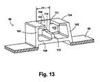
- Figure 13 is a partial cross sectional front perspective view of a dog-house assembly adapted to receive the fastener assembly of Figure 1 ;
- Figure 14 is a bottom perspective view of the fastener assembly of Figure 1 ;
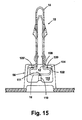
- Figure 15 is a partial cross sectional side elevational view of a sub-assembly of the fastener assembly of Figure 1 engaged with the dog-house assembly of Figure 13 ;
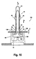
- Figure 16 is a partial cross sectional side elevational view of the fastener sub-assembly of Figure 15 after engagement with a vehicle body panel;
- Figure 17 is a partial cross sectional side elevational view of the fastener subassembly of Figure 15 after partial displacement away from the vehicle body panel;
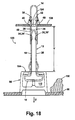
- Figure 18 is a partial cross sectional side elevational view of the fastener subassembly of Figure 15 after full displacement away from the vehicle body panel;
- Figure 19 is a front elevational view of a second embodiment of a fastener of the present disclosure.
- Figure 20 is a side elevational view of the fastener of Figure 19 ;
- Figure 21 is a top plan view of the fastener of Figure 19 ;
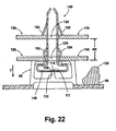
- Figure 22 is a partial cross sectional side elevational view of an assembly of the fastener of Figure 19 to an automotive vehicle panel.
- a fastener assembly 10 includes a first member 12 which is releasably and slidably connected to a second member 14.
- First member 12 includes a rounded base 16 having rounded ends and substantially parallel, opposed first and second legs extending transversely from the rounded base 16.
- First leg 18 includes a first elastically flexible arm 22.
- second leg 20 includes a second elastically flexible arm 24.
- First leg 18 and first elastically flexible arm 22 are oriented as substantially a mirror image configuration of second leg 20 and second elastically flexible arm 24.
- First member 12 can be made of a metal such as spring steel, or from other materials including one or more polymeric materials.
- Second member 14 defines a U-shape and includes first and second body portions 26, 28 which are connected by first and second joining bands 30, 32.
- First and second joining bands 30, 32 are homogenous extensions of first and second body portions 26, 28.
- a first tab 34 and a second tab 36 are homogenous extensions of first body portion 26.
- First and second tabs 34, 36 are formed by a cutting, piercing, stamping, or similar operation performed on first body portion 26 and bent to extend from first body portion 26 toward second body portion 28.
- Second body portion 28 also includes each of a first and second tab 34', 36' which are not clearly visible in this view which are mirror images of first and second tabs 34, 36.
- First body portion 26 also includes each of a first, second, third, and fourth alignment dimple 38, 40, 42, 44.
- First and third alignment dimples 38, 42 are coaxially aligned with first tab 34.
- third and fourth alignment dimples 42, 44 are coaxially aligned with second tab 36.
- Second body portion 28 also includes each of a corresponding first, second, third, and fourth alignment dimples 38', 40', 42', 44' which are mirror image copies of first, second, third and fourth alignment dimples 38, 40, 42, 44,
- Second member 14 can be made of a metal such as spring steel similar to first member 12, or from other materials including one or more polymeric materials.
- First body portion 26 further includes a first engagement member 46 which extends to an opposite direction with respect to first and second tabs 34, 36.
- second body portion 28 includes a second engagement member 48 which is a mirror image configuration of first engagement member 46 and similarly extends away from second body portion 28 in an opposite direction with respect to first and second tabs 34', 36'.
- first member 12 further includes parallel first and second elongated tab receiving slots 50, 52.
- First and second elongated tab receiving slots 50, 52 extend in a direction transverse to rounded base 16 and are each created in first leg 18.
- second leg 20 includes each of a third and fourth elongated tab receiving slot 54, 56 which are mirror image configurations of first and second elongated tab receiving slots 50, 52.
- the elongated tab receiving slots 50, 52, 54, 56 are closed-ended slots and each include at least an end wall 53', 53", 53"', 53"" and opposed side walls 57, 59 respectively.
- Each of a first and second tab alignment member 58, 60 homogenously extend from a free end of first leg 18.
- each of a third and fourth tab alignment member 62, 64 homogenously extend beyond a free end of second leg 20.
- First and second tab alignment members 58, 60 are oriented at an angle with respect to first leg 18 and bent toward each of a third and fourth tab alignment member 62, 64 which each homogenously extend from second leg 20 in a mirror image of first and second tab alignment members 58, 60.
- first assembly alignment member 66 Positioned between first and second tab alignment members 58, 60 is a first assembly alignment member 66 which homogenously extends from first leg 18 and is commonly angled with respect to first and second tab alignment members 58, 60.
- second assembly alignment member 68 is positioned between each of third and fourth tab alignment members 62, 64 homogenously extending from second leg 20, and commonly angled with respect to third and fourth alignment members 62, 64 toward first assembly alignment member 66.
- first member 12 All of the features shown for first member 12 are created from various punching, stamping, bending, or other similar operations performed on a sheet or plate of material such as spring steel or commonly molded from a polymeric material in a single mold operation. Other metal materials or polymeric materials can be substituted for spring steel for either first member 12 or second member 14.
- Spring steel is selected for several embodiments of the present disclosure to provide a spring or bias force tending to retain first and second legs 18, 20 in the general configuration shown in Figure 2 during installation or subsequent use of fastener assembly 10.
- first member 12 can also include a cavity 70 created between first and second elongated tab receiving slots 50, 52 of first leg 18.
- first member 12 can also include a cavity 70' created in second leg 20 between third and fourth elongated tab receiving slots 54, 56.
- First member 12 has a first member height "A”, a first member base width "B”, a first member base height "C”, a leg spacing dimension "D”, a flexible arm non-deflected spacing "E”, and a first member length "F”.
- first member height "A” is approximately 27.0 mm
- first member base width "B” can be approximately 14.4 mm
- first member base height "C” can be approximately 3.2 mm
- leg spacing dimension “D” can be approximately 4.4 mm
- first member length "F” can be approximately 24.0 mm.
- Flexible arm non-deflected spacing "E” is a distance measurable between each of a first flexible arm convex portion 72 and a second flexible arm convex portion 76.
- flexible arm non-deflected spacing "E” can be approximately 7.8 mm.
- a first flexible arm concave portion 74 and a second flexible arm concave portion 78 are each created at a free end of first and second flexible arms 22, 24, respectively.
- each of the first, second, third, and fourth alignment dimples 38, 38', 40, 40', 42, 42', 44, 44' are created on outward facing surfaces of first and second body portions 26, 28.
- a rounded raised surface 80 is therefore created on each of the inward facing surfaces of first and second body portions 26, 28 (i.e.: the surfaces between first and second body portions 26, 28).
- a diameter "X" of each of the rounded raised surfaces 80 is smaller than a span width of the first, second, third, and fourth elongated tab receiving slots 50, 52, 54, 56 shown and described in reference to Figure 2 .
- Each of the rounded raised surfaces 80 are therefore intended to fit within the elongated tab receiving slots 50, 52, 54, 56 to help prevent rotation of the second member 14 when second member 14 is engaged with first member 12 to create fastener assembly 10 (described in reference to Figure 1 ).
- Each of the first and second engagement members 46, 48 also include a first engagement wing 82 and an opposed second engagement wing 84 which extend substantially transverse to a planar surface 85.
- a cavity 86, 86' is created in each of first and second body portions 26, 28 when first tabs 34, 34' are created.
- a cavity 88, 88' is created in each of first and second body portions 26, 28 when second tabs 36, 36' are created.
- second member 14 has a second member width "G" which is substantially equal to first member length "F" described in reference to Figure 5 .
- a second member slot 90 has a second member slot width "H” which allows second member 14 to be slidably received on first member 12 allowing clearance for each of the first and second flexible arms 22, 24.
- Second member 14 also has a second member height "J".
- second member width "G” is approximately 24.0 mm
- second member slot width "H” is approximately 8.0 mm
- second member height "J” is approximately 25.6 mm.
- the dimensions provided herein are for example only and can be modified at the discretion of the manufacturer to suit various sizes and geometries of fastener assemblies 10 of the present disclosure.
- First and second tabs 34, 34', 36, 36' are positioned proximate to free ends of each of first and second body portions 26, 28.
- the free ends of first and second body portions 26, 28 are separated by a first leg spacing dimension "K”.
- the first and second joining bands 30, 32 define a second leg spacing dimension "L”.
- first leg spacing dimension "K” is equal to or less than second leg spacing dimension "L” so that as second member 14 is engaged with first member 12 a spring or biasing force is created by temporary separation of first and second body portions 26, 28 which acts to elastically return first and second body portions 26, 28 to the configuration shown in Figure 8 when first and second tabs 34, 34', 36, 36' engage within the elongated tab receiving slots 50, 52, 54, 56 of first member 12 described in reference to Figure 2 .
- free ends of first and second engagement members 46, 48 are separated by an engagement member spacing dimension "M".
- first leg spacing dimension "K” is approximately 4.9 mm
- second leg spacing dimension "L” is approximately 5.3 mm
- engagement member spacing dimension "M” is approximately 9.3 mm.
- a tab extension dimension "N" of second tab 36 is representative of each of the first and second tabs 34, 34', 36, 36' such that each of the first and second tabs 34, 34', 36, 36' extend from first and second body portions 26, 28 by tab extension dimension "N".
- Both of the first and second engagement members 46, 48 have an engagement member width "P"
- tab extension dimension "N” is approximately 1.5 mm and engagement member width "P” is approximately 7.2 mm.
- second member 14 is shown aligned with but prior to engagement with first member 12.
- first tabs 34, 34', the first alignment dimples 38, 38', and the second alignment dimples 40, 40' are coaxially aligned along a first alignment axis defined through a center of both first and third elongated tab receiving slots 50, 54.
- second tabs 36, 36', third alignment dimples 42, 42', and fourth alignment dimples 44, 44' are coaxially aligned with a center of second and fourth elongated tab receiving slots 52, 56.
- first and second tabs 34, 34' and 36, 36' engage with corresponding ones of the first tab alignment member 58 and third tab alignment member 62, or with second tab alignment member 60 and fourth tab alignment member 64 respectively.
- first and second tabs 34, 34', 36, 36' Sliding engagement of the first and second tabs 34, 34', 36, 36' with the tab alignment members 58, 60, 62, 64 elastically deflects first body portion 26 away from second body portion 28 of second member 14 (by bending at first and second joining bands 30. 32) until by continued engagement in engagement direction "Q" the first and second tabs 34. 34', 36, 36' engage within the elongated tab receiving slots 50, 52, 54, 56.
- each of the first and second tabs 34, 34', 36, 36' can slide within their respective one of the elongated tab receiving slots 50, 52, 54, 56 allowing second member 14 to telescopically slide with respect to first member 12,
- second member 14 in engagement direction "Q" positions the alignment dimples 38, 38', 40, 40', 42, 42', 44, 44' in respective ones of the elongated tab receiving slots 50, 52, 54, 56.
- the alignment dimples 38, 38', 40, 40', 42, 42', 44, 44' thereafter prevent rotation of second member 14 with respect to first member 12.
- both first and second assembly alignment members 66, 68 are positioned proximate to a cavity 97 created between first and second joining bands 30, 32.
- first and second engagement members 46, 48 are freely deflectable within cavities 70, 70'.
- Fastener assembly 10 has a fastener assembly height "R" which according to several embodiments of the present disclosure is approximately 30.6 mm.
- a dog-house 98 can be homogenously connected to a member 99 such as a trim member adapted for installation on an automobile vehicle.
- Dog-house 98 is created from a polymeric material which can be co-molded with the member 99.
- Dog-house 98 includes a first wall 100 and an opposed second wall 102.
- a rear wall 103 together with first and second walls 100, 102 support an upper wall 104.
- a slot 106 is created in upper wall 104 so that dog-house 98 can slidably receive fastener assembly 10 (shown in reference to Figure 15 ).
- a lower wall 108 which is substantially parallel to upper wall 104 provides a beam 110 homogenously extending upwardly as viewed in Figure 13 from lower wall 108 and parallel to slot 106.
- Beam 110 includes a planar surface 111.
- An engagement tooth 114 is homogeneously created on surface 111 proximate to rear wall 103 and extends upwardly as viewed in Figure 13 away from surface 111.
- rounded base 16 of first member 12 of fastener assembly 10 includes an elongated slot 116 created in a substantially flat portion 117 of rounded base 16.
- An edge face 118 defining a first end of elongated slot 116 is provided to engage with the engagement tooth 114 described in reference to Figure 13 when fastener assembly 10 is slidably inserted into cavity 112 of dog-house 98.
- the engagement between edge face 118 and engagement tooth 114 provides a positive engagement of fastener assembly 10 within dog-house 98.
- fastener assembly 10 is shown following horizontal installation within cavity 112 of dog-house 98.
- the lower surface of rounded base 16 is in slidable contact with surface 111 of beam 110.
- an upper surface 120, 120' of rounded base 16 is frictionally engaged with a lower surface 122 of upper wall 104.
- the remaining portions of fastener assembly 10 extend freely and transversely away from dog-house 98 through slot 106.
- a sub-assembly 123 having fastener assembly 10 engaged with dog-house 98 can be used by inserting fastener assembly 10 starting at second member 14 into a longitudinal slot 124 created in a body panel 126 of an automobile vehicle (not shown).
- Fastener assembly 10 is inserted in an insertion direction "S" until an upper surface 128 of dog-house 98 contacts body panel 126.
- First engagement member 46 and second engagement member 48 both elastically deflect toward each other as they are inserted through longitudinal slot 124 then return to their normal extended positions. Subsequently, first and second flexible arms 22, 24 elastically deflect toward each other as first flexible arm convex portion 72 and second flexible arm convex portion 76 pass through longitudinal slot 124.
- First flexible arm concave portion 74 and second flexible arm concave portion 78 are each sized (e.g.: depth and length of curvature) to accommodate a plate thickness "T" of body panel 126.
- plate thickness "T” can range from approximately 0.8 mm to approximately 1.5 mm. This range can be increased or decreased by modifying the geometry of first and second flexible arm concave portions 74, 78.
- a pull force "Y" of approximately 50 pounds is required to displace dog-house 98 from body panel 126 by overcoming the biasing and static friction forces created by first and second flexible arm concave portions 74, 78.
- first and second tabs 34, 34', 36, 36' contact the end walls 53', 53", 53"', 53"" of the elongated tab receiving slots 50, 52, 54, 56 (not visible in this view).
- clearance dimension "V” is provided between body panel 126 and upper wall 104 of dog-house 98.
- clearance dimension "V” can be approximately 24.8 mm.
- Clearance dimension "V” allows manual access to squeeze together first and second body portions 26, 28 as well as first and second legs 18, 20 with a force to inwardly displace first and second engagement members 46, 48 so that first and second engagement members 46, 48 are drawn toward each other and can be withdrawn through longitudinal slot 124 of body panel 126 to completely remove fastener assembly 10 and dog-house 98 from body panel 126.
- Clearance dimension "V” can also provide for limited access between member 99 and body panel 126, for example for installation of electrical wires, tubing, and the like.
- a fastener 140 is created as a single piece, homogenously formed member.
- Fastener 140 includes a rounded base 142 having a flat portion 148 and an elongated aperture 150 similar to rounded base 16, and first and second legs 144, 146 extending substantially transverse to flat portion 148.
- a first flexible arm 152 homogenously connected to first leg 144 is created and oriented similar to first flexible arm 22, first flexible arm 152 having a first flexible arm convex portion 156 and a first flexible arm concave portion 158.
- first and second elastically displaceable engagement members 164, 166 are substantially identical in design and function to first and second engagement members 46, 48, except first and second engagement members 164, 166 are homogenously connected to first and second legs 144, 146 and are not displaceable with respect to rounded base 142.
- Fastener 140 has a fastener height "W”, a base width “Z”, a base height “AA”, and a base length “DD". According to several embodiments, fastener height “W”, base width “Z”, base height “AA”, and base length “DD” are substantially equal to first member height "A”, first member base width "B”, first member base height “C”, and first member length “F” respectively, of fastener assembly 10, so that fastener 140 can engage dog-house 98 and provides a similar space envelope for engagement with vehicle body panel 126. Fastener 140 further includes a flexible arm spacing dimension "BB”, and a flexible arm non-deflected spacing "CC”, which are similar to comparable dimensions of fastener assembly 10.
- fastener 140 is engaged within cavity 112 of dog-house 98 in the same manner as fastener assembly 10.
- An edge face (not shown) of elongated aperture 150 contacts engagement tooth 114 when rounded base 142 is slidably inserted into cavity 112 in a first direction facing away from the viewer as shown in Figure 22 .
- fastener 140 is loaded by pulling or forcing displacement of member 99 in a second direction by a force "Y" (downward as viewed in Figure 22 ) which is substantially transverse to the first direction for installation of fastener 140 in dog-house 98 described above.
- First and second flexible arms 152, 154 releasably engage the walls of aperture 124 of vehicle panel 126 in a first engaged position 168 similar to fastener assembly 10.
- First and second elastically displaceable engagement members 164, 166 contact vehicle body panel 126 in a second engagement position 170 similar to the intermediate engagement position shown in reference to Figure 17 .
- Fastener 140 does not provide the telescoping function of fastener assembly 10, therefore a clearance dimension "EE" between first and second engaged positions 168, 170 of vehicle body panel 126 is less than clearance dimension "V" provided by fastener assembly 10.
- Fastener 140 is also used in applications which can include displacement of vehicle member 99 due to expansion or activation of air bag 130. Similar to fastener assembly 10, a load or force of approximately 50 pounds is also required to displace dog-house 98 from the first engaged position 168 for fastener 140, and a load or force of approximately 200 pounds can be withstood by first and second elastically displaceable engagement members 164, 166 prior to yielding of the material of the engagement members 164, 166.
- member 99 can support or enclose an air bag assembly (not shown) for an automobile vehicle (not shown).
- an air bag assembly (not shown) for an automobile vehicle (not shown).
- a high retention capability of fastener assembly 10 is provided as a pull force defined as approximately 200 pounds or greater is required to yield the material of first and second engagement members 46, 48 or the first and second tabs 34, 34', 36, 36'. Therefore, deployment of the air bag will not cause displacement in displacement direction "U" of sub-assembly 123 in excess of clearance dimension "V", thus retaining member 99 in connection with body panel 126.
- a width "FF" of the slot 106 created in dog-house 98 is adapted to substantially equal or be slightly greater than a spacing between the flexible arm concave portions 74, 78, 158, 162 of fastener assembly 10 and fastener 140, but width "FF" is less than member base width "B” and base width "Z” of fastener assembly 10 and fastener 140.
- the legs (18, 20) of first member 12, and the second member 14 of fastener assembly 10, and the legs 144, 146 of fastener 140 can therefore extend outward of dog-house 98 through slot 106 of dog-house 98.
- Width "FF" prevents rounded base 16 of fastener assembly 10 or rounded base 142 of fastener 140 from being pulled out of cavity 112 when load "Y" is longitudinally or coaxially applied to the fastener (10, 140) which acts to move the rounded base (16, 142) and the dog-house 98 in displacement direction "U”.
- Fastener assemblies 10 of the present disclosure offer several advantages.
- a two-stage telescoping design of fastener assembly 10 provides a normally installed position having fastener assembly 10 fully inserted within a body panel of an automobile vehicle.
- the fastener assembly and dog-house are engaged with a body panel of a vehicle.
- a telescoping or sliding motion of the first and second members 12, 14 of fastener assembly 10 occurs.
- a frictional sliding displacement is restrained at a second stage or position by contact between first and second tabs 34, 34', 36, 36' of second member 14 contacting end walls of tab receiving slots created in first member 12.
- the second, displaced position of fastener assembly 10 allows for manual removal of fastener assembly 10 in addition to providing a clearance space between the member 99 and the body panel 126. Dimples created through the first and second body portions 26, 28 of second member 14 which are positioned within the elongated tab receiving slots of first member 12 provide for fastener assembly alignment and prevent rotation of second member 14 with respect to the first member 12.
- fastener assembly 10 By frictionally engaging a rounded base of fastener assembly 10 within the dog-house, fastener assembly 10 can be slidably fit into the dog-house in a first or horizontal direction. This engagement position prevents withdrawal of the fastener assembly in a second or longitudinal direction of the fastener assembly which is the direction of load application upon release of an air bag assembly.
- This connection of the rounded base into or within a cavity of the dog-house improves on fastener designs having bight members within the fastener which externally engage a spade or blade member extending away from a trim member body, but which can release upon application of an air bag deployment load.
- the rounded base can be manually removed from the dog-house by sliding In an opposite direction from the installation direction, but the second direction is still transverse to the load direction applied during air bag deployment.
- the fastener assembly 10 can also be releasably removed from its second stage engagement with the dog-house by inserting a tool such as a screwdriver into the dog-house and prying the rounded base away from its engagement with the engagement tooth of the dog-house. This provides for complete replacement of fastener assembly 10 and/or complete replacement of member 99.
- the invention relates to:
Priority Applications (1)
| Application Number | Priority Date | Filing Date | Title |
|---|---|---|---|
| EP11169305A EP2364885A1 (de) | 2008-02-15 | 2009-02-13 | In zwei Stufen arbeitende Halterung mit großem Rückhaltevermögen |
Applications Claiming Priority (1)
| Application Number | Priority Date | Filing Date | Title |
|---|---|---|---|
| US12/032,228 US7900953B2 (en) | 2008-02-15 | 2008-02-15 | Two stage high retention fastener |
Publications (2)
| Publication Number | Publication Date |
|---|---|
| EP2090475A1 true EP2090475A1 (de) | 2009-08-19 |
| EP2090475B1 EP2090475B1 (de) | 2011-06-15 |
Family
ID=40626844
Family Applications (2)
| Application Number | Title | Priority Date | Filing Date |
|---|---|---|---|
| EP09002064A Active EP2090475B1 (de) | 2008-02-15 | 2009-02-13 | In zwei Stufen arbeitende Halterung mit großem Rückhaltevermögen |
| EP11169305A Withdrawn EP2364885A1 (de) | 2008-02-15 | 2009-02-13 | In zwei Stufen arbeitende Halterung mit großem Rückhaltevermögen |
Family Applications After (1)
| Application Number | Title | Priority Date | Filing Date |
|---|---|---|---|
| EP11169305A Withdrawn EP2364885A1 (de) | 2008-02-15 | 2009-02-13 | In zwei Stufen arbeitende Halterung mit großem Rückhaltevermögen |
Country Status (5)
| Country | Link |
|---|---|
| US (2) | US7900953B2 (de) |
| EP (2) | EP2090475B1 (de) |
| JP (1) | JP2009192085A (de) |
| AT (1) | ATE512838T1 (de) |
| ES (1) | ES2366466T3 (de) |
Cited By (4)
| Publication number | Priority date | Publication date | Assignee | Title |
|---|---|---|---|---|
| EP0203680A3 (de) * | 1985-03-16 | 1987-09-02 | Marconi Electronic Devices Limited | Gedruckte Schaltung enthaltende elektrische Vorrichtung |
| GB2473918A (en) * | 2009-09-14 | 2011-03-30 | Gm Global Tech Operations Inc | Fastener for a side airbag |
| WO2012022568A1 (de) | 2010-08-20 | 2012-02-23 | A. Raymond Et Cie | Vorrichtung zum halten eines anbauteiles an einem trägerteil sowie anordnung mit einer derartigen vorrichtung und mit einem anbauteil |
| DE102010035011A1 (de) | 2010-08-20 | 2012-02-23 | A. Raymond Et Cie | Vorrichtung zum Halten eines Anbauteiles an einem Trägerteil sowie Anordnung mit einer derartigen Vorrichtung und mit einem Anbauteil |
Families Citing this family (29)
| Publication number | Priority date | Publication date | Assignee | Title |
|---|---|---|---|---|
| DE202007004549U1 (de) * | 2007-03-23 | 2007-06-28 | Takata-Petri Ag | Befestigungsanordnung sowie Werkzeug zum Verriegeln eines Befestigungselementes |
| DE102007045296B3 (de) * | 2007-09-21 | 2008-12-11 | A. Raymond Et Cie | Vorrichtung zum Befestigen von zwei Anbauteilen an einem Trägerteil |
| US8297646B2 (en) * | 2007-11-16 | 2012-10-30 | Piolax Inc. | Clip for airbag |
| FR2938026B1 (fr) * | 2008-11-05 | 2013-01-18 | Saint Gobain | Procede de montage d'une piece sur un cordon profile, dispositif de fixation intermediaire pour la fixation d'une piece sur un cordon profile et utilisation dudit dispositif. |
| JP5370849B2 (ja) * | 2009-12-25 | 2013-12-18 | いすゞ自動車株式会社 | クリップ |
| TWM404093U (en) * | 2010-12-15 | 2011-05-21 | Ks Terminals Inc | Clamp structure |
| US9022415B2 (en) * | 2011-01-11 | 2015-05-05 | Autoliv Development Ab | Cover for airbag device, and airbag device |
| KR101940700B1 (ko) * | 2011-08-29 | 2019-01-21 | 일리노이즈 툴 워크스 인코포레이티드 | 에어백 속박용 클립 조립체 |
| JP5668716B2 (ja) * | 2012-03-30 | 2015-02-12 | トヨタ自動車株式会社 | 取付クリップおよびカーテンエアバッグ取付装置 |
| CN104246242B (zh) * | 2012-04-02 | 2016-05-04 | 百乐仕株式会社 | 夹子以及夹子装置 |
| US8800120B2 (en) | 2012-04-27 | 2014-08-12 | Newfrey Llc | High retention fastener |
| US8615962B1 (en) * | 2013-01-14 | 2013-12-31 | GM Global Technology Operations LLC | Retention feature for automotive deco trim |
| KR101582891B1 (ko) | 2014-10-24 | 2016-01-08 | (주)대한솔루션 | 자동차용 고정구 |
| US9440596B2 (en) * | 2014-11-20 | 2016-09-13 | Ford Global Technologies, Llc | Retention clip for interior vehicle components |
| US9637079B2 (en) * | 2015-04-28 | 2017-05-02 | Toyota Motor Engineering & Manufacturing North America, Inc. | Datum to provide additional retention force |
| WO2017030673A1 (en) * | 2015-08-19 | 2017-02-23 | Toyota Boshoku America, Inc. | Retainer to secure fastener of door trim panel |
| US10288099B2 (en) * | 2015-12-04 | 2019-05-14 | Ford Global Technologies, Llc | Attachment feature for securing two parallel workpieces together |
| DE102016012437A1 (de) * | 2016-10-18 | 2018-04-19 | A.RAYMOND et Cie. SCS | Befestiger zum Sichern eines Halteelements an einem Träger und System umfassend einen Befestiger und ein Halteelement |
| JP7125947B2 (ja) * | 2017-02-28 | 2022-08-25 | スリーエム イノベイティブ プロパティズ カンパニー | 取り付け装置及び関連する方法 |
| US10894516B2 (en) | 2017-10-18 | 2021-01-19 | Newfrey Llc | U-base fastener with folded barb and multiple spring arms |
| US10590968B2 (en) | 2018-03-01 | 2020-03-17 | Newfrey Llc | Dual component U-base fastener |
| CN207961202U (zh) | 2018-01-08 | 2018-10-12 | 福特环球技术公司 | 子零件和零件组件 |
| WO2020023870A1 (en) | 2018-07-27 | 2020-01-30 | Illinois Tool Works Inc. | Fastener assembly and method |
| US11603023B2 (en) * | 2020-02-14 | 2023-03-14 | Waymo Llc | Lockout assembly for folding vehicle seats |
| DE102021111776A1 (de) | 2020-05-11 | 2021-11-11 | Illinois Tool Works Inc. | Blindmontage-befestigungssystem |
| US11542975B2 (en) | 2020-05-11 | 2023-01-03 | Illinois Tool Works Inc. | Blind assembly fastener system |
| US11519442B2 (en) | 2020-05-11 | 2022-12-06 | Illinois Tool Works Inc. | Blind assembly fastener system |
| KR102543535B1 (ko) | 2021-02-09 | 2023-06-16 | 현대모비스 주식회사 | 강화된 융착력의 pab 슈트의 사이드 마운팅 좌면 및 pab 슈트 제조방법 |
| US11746812B2 (en) | 2021-05-12 | 2023-09-05 | Newfrey Llc | Dual component sealing fastener and coupling assembly including same |
Citations (6)
| Publication number | Priority date | Publication date | Assignee | Title |
|---|---|---|---|---|
| JP2000318657A (ja) * | 1999-05-14 | 2000-11-21 | Inoac Corp | 部材固定用クリップ |
| JP2001165134A (ja) * | 1999-12-13 | 2001-06-19 | Inoac Corp | 被固定部材の固定構造 |
| JP2001277985A (ja) * | 2000-03-31 | 2001-10-10 | Piolax Inc | エアバッグ用のクリップ装置 |
| GB2362427A (en) * | 2000-05-18 | 2001-11-21 | Nifco Inc | Component attaching device |
| JP2002067856A (ja) * | 2000-08-25 | 2002-03-08 | Inoac Corp | エアバッグ内蔵式ピラーガーニッシュの取付構造 |
| US20040052575A1 (en) * | 2002-09-13 | 2004-03-18 | Draggoo Kraig D. | Tether clip system |
Family Cites Families (32)
| Publication number | Priority date | Publication date | Assignee | Title |
|---|---|---|---|---|
| US2084717A (en) | 1936-01-24 | 1937-06-22 | William R Wiley | Attaching clip for molding strips |
| US2173524A (en) | 1937-05-28 | 1939-09-19 | John H Van Uum | Spring clip device |
| US2198186A (en) | 1937-07-09 | 1940-04-23 | Tinnerman Products Inc | Clip for moldings and the like |
| US2754561A (en) | 1950-05-05 | 1956-07-17 | United Carr Fastener Corp | Molding fastener |
| US2598776A (en) | 1950-10-23 | 1952-06-03 | Tinnerman Products Inc | Clip for attaching trim objects |
| ZA707246B (en) * | 1969-11-19 | 1971-08-25 | Amp Inc | Fastener |
| US3970346A (en) | 1974-02-19 | 1976-07-20 | Ymos-Mettalwerke | Fastening arrangement for decorative wheel trim |
| JP2545843Y2 (ja) | 1991-05-15 | 1997-08-27 | 東海興業株式会社 | 自動車用モール |
| US5101540A (en) | 1991-08-05 | 1992-04-07 | General Motors Corporation | Lamp housing mounting clip |
| JPH0557407U (ja) | 1992-01-10 | 1993-07-30 | 株式会社豊田自動織機製作所 | 取付部材の止着構造 |
| US5267125A (en) | 1992-10-08 | 1993-11-30 | Enlight Corporation | Flexible grounding element |
| US5639522A (en) * | 1994-07-25 | 1997-06-17 | Tokai Kogyo Co., Ltd. | Side protective moulding for automobiles |
| US5403034A (en) * | 1994-07-28 | 1995-04-04 | Morton International, Inc. | H-rib fastener for detachably fastening an airbag cover to a vehicle instrument panel |
| US5496060A (en) | 1995-01-05 | 1996-03-05 | Morton International, Inc. | One piece detachable cover fastener |
| US5774949A (en) * | 1997-08-27 | 1998-07-07 | Eaton Corporation | Trim clip |
| US6101686A (en) | 1998-03-17 | 2000-08-15 | Daimlerchrysler Corporation | Interior trim spring clip |
| FR2780115B1 (fr) | 1998-06-23 | 2000-08-25 | Eurostyle Sa | Agrafe de fixation |
| EP1057697B1 (de) | 1999-06-02 | 2004-12-29 | Toyoda Gosei Co., Ltd. | Airbag- Kopfschutzvorrichtung mit Klammer zur Erleichterung der Montage-Demontage |
| US20010032377A1 (en) * | 2000-03-27 | 2001-10-25 | Lubera Daniel J. | Resilient clip fastener |
| JP4429492B2 (ja) | 2000-07-25 | 2010-03-10 | マツダ株式会社 | エアバッグ装置 |
| DE20017376U1 (de) | 2000-10-10 | 2001-02-15 | Trw Automotive Electron & Comp | Vorrichtung zur Verbindung eines Trägers, insbesondere eines Karosserieteils eines Kraftfahrzeuges, mit einem Plattenelement, insbesondere einer Tür- oder Wandverkleidung |
| US7165371B2 (en) | 2000-10-13 | 2007-01-23 | Altia Hashimoto Co., Ltd. | Automobile molding and fastener therefor |
| US7640634B2 (en) * | 2002-06-07 | 2010-01-05 | Termax Corporation | Ergonomic fastener |
| JP2003072508A (ja) | 2001-09-03 | 2003-03-12 | Piolax Inc | エアバック装置 |
| US6715185B2 (en) | 2002-07-25 | 2004-04-06 | Illinois Tool Works Inc. | Self aligning panel fastener |
| US7073231B2 (en) | 2002-09-13 | 2006-07-11 | Southco, Inc. | Tether clip system |
| ES2246118B1 (es) | 2004-01-26 | 2007-03-16 | I.T.W. España, S.A. | Pieza de union entre un panel y un soporte. |
| US7086125B2 (en) * | 2004-04-23 | 2006-08-08 | Newfrey Llc | Multiple stage assembly assist fastener |
| US7178855B2 (en) | 2005-03-03 | 2007-02-20 | Lear Corporation | Integral doghouse fastener with retaining feature |
| US7356886B2 (en) | 2005-04-14 | 2008-04-15 | Piolax, Inc. | Clamp |
| US7340808B2 (en) * | 2005-12-19 | 2008-03-11 | International Automotive Components Group North America, Inc. | Dual stage vehicle interior trim fastener |
| US20080028577A1 (en) * | 2006-08-03 | 2008-02-07 | Mangesh Soman | Resilient two stage clip for automotive application |
-
2008
- 2008-02-15 US US12/032,228 patent/US7900953B2/en active Active
-
2009
- 2009-02-13 EP EP09002064A patent/EP2090475B1/de active Active
- 2009-02-13 ES ES09002064T patent/ES2366466T3/es active Active
- 2009-02-13 EP EP11169305A patent/EP2364885A1/de not_active Withdrawn
- 2009-02-13 AT AT09002064T patent/ATE512838T1/de not_active IP Right Cessation
- 2009-02-13 JP JP2009055665A patent/JP2009192085A/ja active Pending
-
2011
- 2011-03-07 US US13/041,771 patent/US8038167B2/en active Active
Patent Citations (6)
| Publication number | Priority date | Publication date | Assignee | Title |
|---|---|---|---|---|
| JP2000318657A (ja) * | 1999-05-14 | 2000-11-21 | Inoac Corp | 部材固定用クリップ |
| JP2001165134A (ja) * | 1999-12-13 | 2001-06-19 | Inoac Corp | 被固定部材の固定構造 |
| JP2001277985A (ja) * | 2000-03-31 | 2001-10-10 | Piolax Inc | エアバッグ用のクリップ装置 |
| GB2362427A (en) * | 2000-05-18 | 2001-11-21 | Nifco Inc | Component attaching device |
| JP2002067856A (ja) * | 2000-08-25 | 2002-03-08 | Inoac Corp | エアバッグ内蔵式ピラーガーニッシュの取付構造 |
| US20040052575A1 (en) * | 2002-09-13 | 2004-03-18 | Draggoo Kraig D. | Tether clip system |
Cited By (12)
| Publication number | Priority date | Publication date | Assignee | Title |
|---|---|---|---|---|
| EP0203680A3 (de) * | 1985-03-16 | 1987-09-02 | Marconi Electronic Devices Limited | Gedruckte Schaltung enthaltende elektrische Vorrichtung |
| GB2473918A (en) * | 2009-09-14 | 2011-03-30 | Gm Global Tech Operations Inc | Fastener for a side airbag |
| CN102019898A (zh) * | 2009-09-14 | 2011-04-20 | 通用汽车环球科技运作公司 | 固定器件和用于触发侧气囊的方法 |
| US8220827B2 (en) | 2009-09-14 | 2012-07-17 | GM Global Technology Operations LLC | Fastener and method for triggering a side airbag |
| CN102019898B (zh) * | 2009-09-14 | 2015-11-25 | 通用汽车环球科技运作公司 | 固定器件和用于触发侧气囊的方法 |
| GB2473918B (en) * | 2009-09-14 | 2016-03-02 | Gm Global Tech Operations Inc | Fastener for retaining displaceable panel in the event of an airbag being deployed |
| WO2012022568A1 (de) | 2010-08-20 | 2012-02-23 | A. Raymond Et Cie | Vorrichtung zum halten eines anbauteiles an einem trägerteil sowie anordnung mit einer derartigen vorrichtung und mit einem anbauteil |
| DE102010035011A1 (de) | 2010-08-20 | 2012-02-23 | A. Raymond Et Cie | Vorrichtung zum Halten eines Anbauteiles an einem Trägerteil sowie Anordnung mit einer derartigen Vorrichtung und mit einem Anbauteil |
| DE102010035012A1 (de) | 2010-08-20 | 2012-02-23 | A. Raymond Et Cie | Vorrichtung zum Halten eines Anbauteiles an einem Trägerteil sowie Anordnung mit einer derartigen Vorrichtung und mit einem Anbauteil |
| WO2012022545A1 (de) | 2010-08-20 | 2012-02-23 | A. Raymond Et Cie | Vorrichtung zum halten eines anbauteiles an einem trägerteil sowie anordnung mit einer derartigen vorrichtung und mit einem anbauteil |
| US8944733B2 (en) | 2010-08-20 | 2015-02-03 | A. Raymond Et Cie | Device for holding an add-on part on a support part, and arrangement with a device of this type and with an add-on part |
| US8961092B2 (en) | 2010-08-20 | 2015-02-24 | A. Raymond et Cie | Device for retaining an attached part on a carrier part and arrangement having such a device and having an attached part |
Also Published As
| Publication number | Publication date |
|---|---|
| EP2364885A1 (de) | 2011-09-14 |
| EP2090475B1 (de) | 2011-06-15 |
| US20090205174A1 (en) | 2009-08-20 |
| US7900953B2 (en) | 2011-03-08 |
| JP2009192085A (ja) | 2009-08-27 |
| US8038167B2 (en) | 2011-10-18 |
| US20110156377A1 (en) | 2011-06-30 |
| ATE512838T1 (de) | 2011-07-15 |
| ES2366466T3 (es) | 2011-10-20 |
Similar Documents
| Publication | Publication Date | Title |
|---|---|---|
| US8038167B2 (en) | Two stage high retention fastener | |
| US7188393B2 (en) | Fastener device | |
| JP5048263B2 (ja) | Wベース型留具 | |
| US7891926B2 (en) | Fastener | |
| WO2014020655A1 (ja) | 固定具、固定具抜去構造およびカーテンエアバッグ固定装置 | |
| US10677277B2 (en) | Fastening clip | |
| JP6851884B2 (ja) | クリップ | |
| EP2813397A1 (de) | Klemme | |
| US10202995B2 (en) | Self-locking edge clip fastener | |
| EP1783005A1 (de) | Stossstangenbefestigung | |
| CN111255787B (zh) | 夹持元件、用于组装夹持元件的方法、用于夹持夹持元件的方法和元件和夹持元件的系统 | |
| JP2005308221A (ja) | 多段組み立て補助ファスナ | |
| CN108713104B (zh) | 自加强夹 | |
| EP3446847B1 (de) | Element zum zeitweiligen halten einer komponente und komponentenbefestigungswerkzeug | |
| KR20080004379A (ko) | 클립 | |
| US20120085874A1 (en) | Device for fastening a connector piece to a carrier piece and fastening arrangement having such a device | |
| KR20070114039A (ko) | 2피스 클립 | |
| CN108291567B (zh) | 卡扣 | |
| EP3495670A1 (de) | Befestigungselement mit hoher haltekraft | |
| US8622680B1 (en) | Grommet | |
| US7871102B2 (en) | Air bag fastener assembly | |
| EP3364051B1 (de) | Verfahren zum befestigen eines bogenartigen elements auf einem anbauteil mittels befestigungsvorrichtung und zusammenbauanordnung | |
| JP2012167694A (ja) | 留め具構造 | |
| CN107084177B (zh) | 紧固件及部件安装构造 | |
| JP2006057647A (ja) | 車両用アクセサリの固定装置 |
Legal Events
| Date | Code | Title | Description |
|---|---|---|---|
| PUAI | Public reference made under article 153(3) epc to a published international application that has entered the european phase |
Free format text: ORIGINAL CODE: 0009012 |
|
| AK | Designated contracting states |
Kind code of ref document: A1 Designated state(s): AT BE BG CH CY CZ DE DK EE ES FI FR GB GR HR HU IE IS IT LI LT LU LV MC MK MT NL NO PL PT RO SE SI SK TR |
|
| AX | Request for extension of the european patent |
Extension state: AL BA RS |
|
| 17P | Request for examination filed |
Effective date: 20100122 |
|
| 17Q | First examination report despatched |
Effective date: 20100216 |
|
| AKX | Designation fees paid |
Designated state(s): AT BE BG CH CY CZ DE DK EE ES FI FR GB GR HR HU IE IS IT LI LT LU LV MC MK MT NL NO PL PT RO SE SI SK TR |
|
| GRAP | Despatch of communication of intention to grant a patent |
Free format text: ORIGINAL CODE: EPIDOSNIGR1 |
|
| GRAS | Grant fee paid |
Free format text: ORIGINAL CODE: EPIDOSNIGR3 |
|
| GRAA | (expected) grant |
Free format text: ORIGINAL CODE: 0009210 |
|
| AK | Designated contracting states |
Kind code of ref document: B1 Designated state(s): AT BE BG CH CY CZ DE DK EE ES FI FR GB GR HR HU IE IS IT LI LT LU LV MC MK MT NL NO PL PT RO SE SI SK TR |
|
| REG | Reference to a national code |
Ref country code: GB Ref legal event code: FG4D Ref country code: CH Ref legal event code: EP |
|
| REG | Reference to a national code |
Ref country code: IE Ref legal event code: FG4D |
|
| REG | Reference to a national code |
Ref country code: DE Ref legal event code: R096 Ref document number: 602009001510 Country of ref document: DE Effective date: 20110728 |
|
| REG | Reference to a national code |
Ref country code: NL Ref legal event code: VDEP Effective date: 20110615 |
|
| REG | Reference to a national code |
Ref country code: ES Ref legal event code: FG2A Ref document number: 2366466 Country of ref document: ES Kind code of ref document: T3 Effective date: 20111020 |
|
| PG25 | Lapsed in a contracting state [announced via postgrant information from national office to epo] |
Ref country code: LT Free format text: LAPSE BECAUSE OF FAILURE TO SUBMIT A TRANSLATION OF THE DESCRIPTION OR TO PAY THE FEE WITHIN THE PRESCRIBED TIME-LIMIT Effective date: 20110615 Ref country code: HR Free format text: LAPSE BECAUSE OF FAILURE TO SUBMIT A TRANSLATION OF THE DESCRIPTION OR TO PAY THE FEE WITHIN THE PRESCRIBED TIME-LIMIT Effective date: 20110615 Ref country code: SE Free format text: LAPSE BECAUSE OF FAILURE TO SUBMIT A TRANSLATION OF THE DESCRIPTION OR TO PAY THE FEE WITHIN THE PRESCRIBED TIME-LIMIT Effective date: 20110615 Ref country code: NO Free format text: LAPSE BECAUSE OF FAILURE TO SUBMIT A TRANSLATION OF THE DESCRIPTION OR TO PAY THE FEE WITHIN THE PRESCRIBED TIME-LIMIT Effective date: 20110915 |
|
| PG25 | Lapsed in a contracting state [announced via postgrant information from national office to epo] |
Ref country code: SI Free format text: LAPSE BECAUSE OF FAILURE TO SUBMIT A TRANSLATION OF THE DESCRIPTION OR TO PAY THE FEE WITHIN THE PRESCRIBED TIME-LIMIT Effective date: 20110615 Ref country code: CY Free format text: LAPSE BECAUSE OF FAILURE TO SUBMIT A TRANSLATION OF THE DESCRIPTION OR TO PAY THE FEE WITHIN THE PRESCRIBED TIME-LIMIT Effective date: 20110615 Ref country code: GR Free format text: LAPSE BECAUSE OF FAILURE TO SUBMIT A TRANSLATION OF THE DESCRIPTION OR TO PAY THE FEE WITHIN THE PRESCRIBED TIME-LIMIT Effective date: 20110916 Ref country code: FI Free format text: LAPSE BECAUSE OF FAILURE TO SUBMIT A TRANSLATION OF THE DESCRIPTION OR TO PAY THE FEE WITHIN THE PRESCRIBED TIME-LIMIT Effective date: 20110615 Ref country code: LV Free format text: LAPSE BECAUSE OF FAILURE TO SUBMIT A TRANSLATION OF THE DESCRIPTION OR TO PAY THE FEE WITHIN THE PRESCRIBED TIME-LIMIT Effective date: 20110615 Ref country code: AT Free format text: LAPSE BECAUSE OF FAILURE TO SUBMIT A TRANSLATION OF THE DESCRIPTION OR TO PAY THE FEE WITHIN THE PRESCRIBED TIME-LIMIT Effective date: 20110615 |
|
| PG25 | Lapsed in a contracting state [announced via postgrant information from national office to epo] |
Ref country code: BE Free format text: LAPSE BECAUSE OF FAILURE TO SUBMIT A TRANSLATION OF THE DESCRIPTION OR TO PAY THE FEE WITHIN THE PRESCRIBED TIME-LIMIT Effective date: 20110615 Ref country code: NL Free format text: LAPSE BECAUSE OF FAILURE TO SUBMIT A TRANSLATION OF THE DESCRIPTION OR TO PAY THE FEE WITHIN THE PRESCRIBED TIME-LIMIT Effective date: 20110615 |
|
| PG25 | Lapsed in a contracting state [announced via postgrant information from national office to epo] |
Ref country code: PT Free format text: LAPSE BECAUSE OF FAILURE TO SUBMIT A TRANSLATION OF THE DESCRIPTION OR TO PAY THE FEE WITHIN THE PRESCRIBED TIME-LIMIT Effective date: 20111017 Ref country code: IS Free format text: LAPSE BECAUSE OF FAILURE TO SUBMIT A TRANSLATION OF THE DESCRIPTION OR TO PAY THE FEE WITHIN THE PRESCRIBED TIME-LIMIT Effective date: 20111015 Ref country code: EE Free format text: LAPSE BECAUSE OF FAILURE TO SUBMIT A TRANSLATION OF THE DESCRIPTION OR TO PAY THE FEE WITHIN THE PRESCRIBED TIME-LIMIT Effective date: 20110615 Ref country code: CZ Free format text: LAPSE BECAUSE OF FAILURE TO SUBMIT A TRANSLATION OF THE DESCRIPTION OR TO PAY THE FEE WITHIN THE PRESCRIBED TIME-LIMIT Effective date: 20110615 |
|
| PG25 | Lapsed in a contracting state [announced via postgrant information from national office to epo] |
Ref country code: SK Free format text: LAPSE BECAUSE OF FAILURE TO SUBMIT A TRANSLATION OF THE DESCRIPTION OR TO PAY THE FEE WITHIN THE PRESCRIBED TIME-LIMIT Effective date: 20110615 Ref country code: RO Free format text: LAPSE BECAUSE OF FAILURE TO SUBMIT A TRANSLATION OF THE DESCRIPTION OR TO PAY THE FEE WITHIN THE PRESCRIBED TIME-LIMIT Effective date: 20110615 Ref country code: PL Free format text: LAPSE BECAUSE OF FAILURE TO SUBMIT A TRANSLATION OF THE DESCRIPTION OR TO PAY THE FEE WITHIN THE PRESCRIBED TIME-LIMIT Effective date: 20110615 |
|
| PLBE | No opposition filed within time limit |
Free format text: ORIGINAL CODE: 0009261 |
|
| STAA | Information on the status of an ep patent application or granted ep patent |
Free format text: STATUS: NO OPPOSITION FILED WITHIN TIME LIMIT |
|
| 26N | No opposition filed |
Effective date: 20120316 |
|
| PG25 | Lapsed in a contracting state [announced via postgrant information from national office to epo] |
Ref country code: DK Free format text: LAPSE BECAUSE OF FAILURE TO SUBMIT A TRANSLATION OF THE DESCRIPTION OR TO PAY THE FEE WITHIN THE PRESCRIBED TIME-LIMIT Effective date: 20110615 |
|
| REG | Reference to a national code |
Ref country code: DE Ref legal event code: R097 Ref document number: 602009001510 Country of ref document: DE Effective date: 20120316 |
|
| PG25 | Lapsed in a contracting state [announced via postgrant information from national office to epo] |
Ref country code: MC Free format text: LAPSE BECAUSE OF NON-PAYMENT OF DUE FEES Effective date: 20120229 |
|
| REG | Reference to a national code |
Ref country code: IE Ref legal event code: MM4A |
|
| PG25 | Lapsed in a contracting state [announced via postgrant information from national office to epo] |
Ref country code: IE Free format text: LAPSE BECAUSE OF NON-PAYMENT OF DUE FEES Effective date: 20120213 |
|
| PG25 | Lapsed in a contracting state [announced via postgrant information from national office to epo] |
Ref country code: MK Free format text: LAPSE BECAUSE OF FAILURE TO SUBMIT A TRANSLATION OF THE DESCRIPTION OR TO PAY THE FEE WITHIN THE PRESCRIBED TIME-LIMIT Effective date: 20110615 |
|
| PG25 | Lapsed in a contracting state [announced via postgrant information from national office to epo] |
Ref country code: BG Free format text: LAPSE BECAUSE OF FAILURE TO SUBMIT A TRANSLATION OF THE DESCRIPTION OR TO PAY THE FEE WITHIN THE PRESCRIBED TIME-LIMIT Effective date: 20110915 |
|
| PG25 | Lapsed in a contracting state [announced via postgrant information from national office to epo] |
Ref country code: MT Free format text: LAPSE BECAUSE OF FAILURE TO SUBMIT A TRANSLATION OF THE DESCRIPTION OR TO PAY THE FEE WITHIN THE PRESCRIBED TIME-LIMIT Effective date: 20110615 |
|
| REG | Reference to a national code |
Ref country code: CH Ref legal event code: PL |
|
| PG25 | Lapsed in a contracting state [announced via postgrant information from national office to epo] |
Ref country code: LI Free format text: LAPSE BECAUSE OF NON-PAYMENT OF DUE FEES Effective date: 20130228 Ref country code: CH Free format text: LAPSE BECAUSE OF NON-PAYMENT OF DUE FEES Effective date: 20130228 |
|
| PG25 | Lapsed in a contracting state [announced via postgrant information from national office to epo] |
Ref country code: TR Free format text: LAPSE BECAUSE OF FAILURE TO SUBMIT A TRANSLATION OF THE DESCRIPTION OR TO PAY THE FEE WITHIN THE PRESCRIBED TIME-LIMIT Effective date: 20110615 |
|
| PG25 | Lapsed in a contracting state [announced via postgrant information from national office to epo] |
Ref country code: LU Free format text: LAPSE BECAUSE OF NON-PAYMENT OF DUE FEES Effective date: 20120213 |
|
| PGFP | Annual fee paid to national office [announced via postgrant information from national office to epo] |
Ref country code: ES Payment date: 20140226 Year of fee payment: 6 Ref country code: IT Payment date: 20140221 Year of fee payment: 6 |
|
| PG25 | Lapsed in a contracting state [announced via postgrant information from national office to epo] |
Ref country code: HU Free format text: LAPSE BECAUSE OF FAILURE TO SUBMIT A TRANSLATION OF THE DESCRIPTION OR TO PAY THE FEE WITHIN THE PRESCRIBED TIME-LIMIT Effective date: 20090213 |
|
| PG25 | Lapsed in a contracting state [announced via postgrant information from national office to epo] |
Ref country code: IT Free format text: LAPSE BECAUSE OF NON-PAYMENT OF DUE FEES Effective date: 20150213 |
|
| REG | Reference to a national code |
Ref country code: FR Ref legal event code: PLFP Year of fee payment: 8 |
|
| REG | Reference to a national code |
Ref country code: ES Ref legal event code: FD2A Effective date: 20160329 |
|
| PG25 | Lapsed in a contracting state [announced via postgrant information from national office to epo] |
Ref country code: ES Free format text: LAPSE BECAUSE OF NON-PAYMENT OF DUE FEES Effective date: 20150214 |
|
| REG | Reference to a national code |
Ref country code: FR Ref legal event code: PLFP Year of fee payment: 9 |
|
| REG | Reference to a national code |
Ref country code: FR Ref legal event code: PLFP Year of fee payment: 10 |
|
| PGFP | Annual fee paid to national office [announced via postgrant information from national office to epo] |
Ref country code: CH Payment date: 20190320 Year of fee payment: 5 Ref country code: FR Payment date: 20190111 Year of fee payment: 11 |
|
| GBPC | Gb: european patent ceased through non-payment of renewal fee |
Effective date: 20200213 |
|
| PG25 | Lapsed in a contracting state [announced via postgrant information from national office to epo] |
Ref country code: FR Free format text: LAPSE BECAUSE OF NON-PAYMENT OF DUE FEES Effective date: 20200229 Ref country code: GB Free format text: LAPSE BECAUSE OF NON-PAYMENT OF DUE FEES Effective date: 20200213 |
|
| PGFP | Annual fee paid to national office [announced via postgrant information from national office to epo] |
Ref country code: DE Payment date: 20221220 Year of fee payment: 15 |