EP2089692B1 - Sensoreinheit für eine spr- (surface plasmon resonance-)einheit - Google Patents
Sensoreinheit für eine spr- (surface plasmon resonance-)einheit Download PDFInfo
- Publication number
- EP2089692B1 EP2089692B1 EP07835150.9A EP07835150A EP2089692B1 EP 2089692 B1 EP2089692 B1 EP 2089692B1 EP 07835150 A EP07835150 A EP 07835150A EP 2089692 B1 EP2089692 B1 EP 2089692B1
- Authority
- EP
- European Patent Office
- Prior art keywords
- sensor unit
- unit
- sample
- sensor
- substrate
- Prior art date
- Legal status (The legal status is an assumption and is not a legal conclusion. Google has not performed a legal analysis and makes no representation as to the accuracy of the status listed.)
- Active
Links
Images


Classifications
-
- G—PHYSICS
- G01—MEASURING; TESTING
- G01N—INVESTIGATING OR ANALYSING MATERIALS BY DETERMINING THEIR CHEMICAL OR PHYSICAL PROPERTIES
- G01N21/00—Investigating or analysing materials by the use of optical means, i.e. using sub-millimetre waves, infrared, visible or ultraviolet light
- G01N21/17—Systems in which incident light is modified in accordance with the properties of the material investigated
- G01N21/55—Specular reflectivity
- G01N21/552—Attenuated total reflection
- G01N21/553—Attenuated total reflection and using surface plasmons
-
- G—PHYSICS
- G01—MEASURING; TESTING
- G01N—INVESTIGATING OR ANALYSING MATERIALS BY DETERMINING THEIR CHEMICAL OR PHYSICAL PROPERTIES
- G01N21/00—Investigating or analysing materials by the use of optical means, i.e. using sub-millimetre waves, infrared, visible or ultraviolet light
- G01N21/01—Arrangements or apparatus for facilitating the optical investigation
- G01N21/03—Cuvette constructions
-
- G—PHYSICS
- G01—MEASURING; TESTING
- G01N—INVESTIGATING OR ANALYSING MATERIALS BY DETERMINING THEIR CHEMICAL OR PHYSICAL PROPERTIES
- G01N33/00—Investigating or analysing materials by specific methods not covered by groups G01N1/00 - G01N31/00
- G01N33/48—Biological material, e.g. blood, urine; Haemocytometers
- G01N33/50—Chemical analysis of biological material, e.g. blood, urine; Testing involving biospecific ligand binding methods; Immunological testing
- G01N33/53—Immunoassay; Biospecific binding assay; Materials therefor
- G01N33/543—Immunoassay; Biospecific binding assay; Materials therefor with an insoluble carrier for immobilising immunochemicals
-
- G—PHYSICS
- G01—MEASURING; TESTING
- G01N—INVESTIGATING OR ANALYSING MATERIALS BY DETERMINING THEIR CHEMICAL OR PHYSICAL PROPERTIES
- G01N21/00—Investigating or analysing materials by the use of optical means, i.e. using sub-millimetre waves, infrared, visible or ultraviolet light
- G01N21/01—Arrangements or apparatus for facilitating the optical investigation
- G01N21/03—Cuvette constructions
- G01N21/0303—Optical path conditioning in cuvettes, e.g. windows; adapted optical elements or systems; path modifying or adjustment
- G01N2021/0307—Insert part in cell
-
- G—PHYSICS
- G01—MEASURING; TESTING
- G01N—INVESTIGATING OR ANALYSING MATERIALS BY DETERMINING THEIR CHEMICAL OR PHYSICAL PROPERTIES
- G01N21/00—Investigating or analysing materials by the use of optical means, i.e. using sub-millimetre waves, infrared, visible or ultraviolet light
- G01N21/01—Arrangements or apparatus for facilitating the optical investigation
- G01N21/03—Cuvette constructions
- G01N2021/0346—Capillary cells; Microcells
Definitions
- the present invention relates to a method, apparatus and device for optical surface analysis of a plurality of sample areas on a curved sensor unit using surface plasmon resonance.
- the invention is particularly concerned with a rotational symmetric container or tube or a device using an angular part of a rotational symmetric container, using surface plasmon resonance (SPR), suitable for use in biological, biochemical, chemical and physical analyzing, as well as gas sensing, where the container or tube may be fixed or movable, e.g. rotating or oscillating.
- SPR surface plasmon resonance
- SPR is a well-known phenomenon that is a bound electromagnetic wave, due to oscillations of electrons at the interface between a plasma and a dielectricum.
- the most common way to design an SPR apparatus is to use a prism (triangular, hemispherical or an arbitrary shape) and apply to the prism a separate planar substrate carrying the SPR-metal.
- a refractive index matching material between the prism and substrate to obtain good optical coupling.
- the material can either be an opto-gel or a refractive index matching fluid.
- the use of an opto-gel has the disadvantage of wear, optical imperfection and high cost.
- a refractive index matching fluid is used, a circumstantial procedure of application and cleaning is needed, besides the extra cost.
- a prism with evaporated metal film and SPR-light-pipe Karlsen, S. R., et al.Chemical, 1996, 35-36: p. 212-216
- the fiber optic SPR one can refrain from using an optical coupling medium, but for the case of an exchangeable probe, a coupling medium is needed.
- planar sensor surface with multiple sensor areas arranged in a two-dimensional way, means that there are a couple of somewhat cumbersome (and expensive) ways to read the optical output from the surface plasmon resonance device.
- there are two methods to perform a readout by mechanically scan the sensor substrate, or the use of imaging optics. Not only is the read out complex, but the distribution of samples for investigation is often very complex, with use of valves and channels or expensive autosamplers.
- approaches that do not use planar substrates Chinowsky et al. are using an approach, where a capillary tube is used, patent US 6,480,282 . The tube wall itself is the then the coupling medium, and no index matching fluid is necessary.
- the capillary is useful for multi sensor configuration, where the other techniques can be critical angle detection, fluorescence, chemiluminiscence, adsorption or Raman scattering. It can, with difficulties be used as an axial multispot sensor, and with severe difficulties may be with some sensors spots radially separated.
- this approach has several disadvantages. It is very difficult to cover the inside of the capillary tube with a metal of precise thickness, due to the small diameter and long length. Capillary tubes are not normally high precision optics, which will distort optical images.
- the capillary device is suitable for one or a few sensing spots, and the small diameter means that there will be difficulties to manufacture device with many sensors spots.
- the capillary device has typically a relatively large diameter, e.g. 400 pm, compared to a thin flowcell, e.g. 10 pm, making the capillary tube inefficient regarding small sample volumes, and mass transport.
- This device uses curved cavities for recognition sites, preferably many cavities are used for a multi spot sensor.
- the cavity can be cylindrical, spherical or an arbitrary curvature, and the surface plasmon is exited radially, as described by Chinowsky. However, the outer surface, which is hit by the incident light, is planar.
- the proposed cavity is not intended for multiple sensor areas.
- a SPR-setup utilizing a convex curved SPR-supporting surface is described by Rooney et al., Sensors and Actuators B, 26 April 2006 . There is also described a SPR-setup consisting of a tubular cup, where a SPR-supporting layer is present on the planar bottom, EP 1186881 , Haya et al., 2002 (Fuji Photo Film Co).
- the object of the invention is to provide an improved SPR device enabling e.g. analysis of multiple samples in a simple manner, and also which is easy and inexpensive to manufacture.
- a sensor unit comprising a transparent sensor structure forming at least one wall of a cavity, the wall being defined by a concave inner surface and a convex outer surface; wherein the inner surface is provided with a layer of a conductive material capable of supporting a surface plasmon; a flow structure in said cavity so as to form at least one compartment for sample between the flow structure and the inner wall of the cavity.
- the flow structure is suitably provided as an insert fitting in the cavity, the insert being configured and structured so as to provide the required channels, compartments or other spaces necessary to accommodate a sample.
- the configuration of the inset makes it also ideal for precise temperature control of the sample.
- a sensor unit device with convex curved outer surface and concave inner surface, in one or two dimensions is used (e.g. cylinder or hemisphere).
- the inner surface is, at least partly, covered with a conductive layer, having the possibility to carry a surface plasmon.
- the device is a development from the planar structure having the possibility to incorporate multiple recognition sites in one or two dimensions.
- the curvatures of both the outer and inner surfaces means that the structure itself acts as an optical device eliminating expensive optics for light sources and detectors, e.g.
- a collimated incident beam will be transformed to a multi angle beam incorporating incident angles of interest by the curved outer and inner surfaces, and further spread to a detector, without the use of other optics.
- the use of macroscopic dimensions like in the conventional planar configuration means that a flow structure is easily incorporated close to or in contact with the inner surface.
- the flow structure can in its simplest form be a wall close to the inner surface, incorporated in the optical structure. Such a wall can decrease sample volumes, without decreasing the advantage of macroscopic size of the sensor unit.
- versatile fluidistics can be formed, both for immobilization of recognition molecules and samples.
- the curvature makes the device ideal for rotation, whereas different rows of recognition sites can be addressed both optically and by the flow cells in a single operation, eliminating expensive fluidistics.
- it is ideal as a diagnostic revolver, where one or more analytes are measured by one or more sensor sports axially, and different samples are analyzed by rotating the device, using new sensor spots, for the same or different analytes.
- the surface plasmon is exited radially, and one embodiment is a closed structure, another is an open one, where an angular part of the structure is missing, e.g. a tube which is axially cut in half.
- a rotational symmetry makes the device ideal for monitoring of substances or the formation of new substances close to the wall.
- the shape of the device makes it ideal for multi-spot and large area detection. The shape makes it easy to scan the whole inner surface of the device by either rotating the device or by rotating the light source and detector.
- a rotational symmetry and macroscopic dimensions are ideal for an insert containing a flow system with sample distribution. Use of macroscopic dimensions leads to simpler optics where beam widths from commercial components can be used with optical output that generates surface plasmon resonance angles of interest, e.g. for effective refractive indices from e.g. 1.33 to 1.45.
- the invention can be used for biosensing, e.g., for monitoring of chemical and biological reactions in real time with label-free molecules.
- a set-up with a collimated light source in a new configuration with gold as the supporting metal is described, both theoretically and experimentally.
- Simulations of the sensor response based on independently recorded optical (ellipsometric) data of gold show that the proposed optical set up working as a surface sensitive differential refractometer, where the performance is equal or better than contemporary instruments.
- a closed configuration of the sample area makes it ideal also for gas sensing.
- the main advantages of the invention are: Simpler and cheaper instrument and consumables can be produced.
- the elimination of a refractive index matching layer (as used in the Kretschmann configuration) means that the handling and change of sensors surfaces are easily performed.
- a rotational or partly rotational symmetry of the sensor surface means that it can be used in conjunction with a rotating bob creating shear rates and a more effective mass transport of the analyte to the sensing surface
- the use of a conical bob and/or vial means that a gradient of the immobilized molecules can easily be created. Furthermore, due to different mass transport conditions, a gradient of the free analyte can also be created. These properties make it possible to perform an effective interaction analysis.
- the design as a circular container means that a sample and flow handling system can be integrated inside the cavity. Even the waste can be integrated, e.g. for safety reasons.
- the SPR tube, cup or vial can have the advantage of utilizing the rotational symmetric configuration, where the wall acts as a coupling medium, which increases the propagation vector parallel to the inner surface of the tube, making it possible to excite a surface plasmon.
- the use of the wall means that no refractive index matching medium, e.g. fluid, gel or film, is necessary, leading to a simple and cheap set up. Furthermore, the handling and change of sensor surfaces are then very simple.
- a rotational symmetric structure of the tube/vial means that the tube/vial can be rotated and scanned over the whole inner surface, making it ideal for multi-spot measurements.
- a rotational symmetric configuration make it possible to place inserts within the vial/tube which are easily sealed.
- the SPR tube/vial is conical, a correspondingly conical insert will be self-positioned and self-tightened, by virtue of it fitting exactly in the cavity, making it an ideal structure for an integrated flow system, as will be disclosed below in detail.
- the system can also be made leakage proof. It is also ideal when a bob (fixed or rotating) is used. The rotation of the bob relative the tube/vial makes it possible to monitor interactions, adlayer formations, and conformal changes at different shear rates.
- the SPR-vial can efficiently be used in the monitoring of polymerization and depolymerization processes, e.g. hemostasis.
- the polarization state i.e. ellipsometric measurements can be performed, using both p- and s-polarized light.
- Severeral ellipsometric techniques are well known for planar structures, such as null ellipsometry, off null ellipsometry, rotatating analyzer etc, which all can be used in the proposed structure.
- a sandwich assay can be used, where an immobilized molecule act as capturing molecule for an analyte molecule, and a third molecule is attached to the analyte either by mixing in the sample or by a further reagent step.
- the third molecule can be a large molecule, or have high refractive index or using both properties.
- the propagation constant of a plasmon can be calculated from Maxwells Equations.
- a one-dimensional SPR measurement (measurement of a single line) the intensity measurement requires a one-dimensional (line) detector to make an instant measurement of the position of an SPR-dip. If a two dimensional (matrix) detector is used, a two-dimensional sensor surface can be monitored.
- the intensity measurement has the disadvantage that only a small part of the SPR-dip is measured. This can lead to false interpretations, if, e.g. the dip is broadening or influenced by a drifting offset. If the whole dip is measured as in the angular and wavelength interrogation, these drawbacks are eliminated or at least significantly reduced. If the angular or wavelength interrogation is used, one dimension of the sensor surface is eliminated and replaced by an SPR-dip, i.e.
- a two-dimensional detector can monitor a line, and a one line-detector can monitor a spot.
- one dimension is used for the length scale (real image) and one dimension is used for the dip (either angle or wavelength).
- the SPR-tube/vial is rotated, a fully two-dimensional surface can be monitored by a two-dimensional detector, measuring the whole SPR-dip, and a line can be monitored by a one-dimensional detector, using this scanning technique.
- the preferred detection method for the SPR-tube/vial is the angular interrogation. If a collimated (parallel) or slightly divergent or convergent light is used, the light beam will hit the outer wall of the tube/vial and refract into the inner surface at a continuum of incident angles due to the width of the beam. The total internal reflected beam will be further refracted at the outer surface, creating a divergent beam, where the SPR-dip (angular) are easily monitored by a photo-detector or a photographic film.
- the width of the beam will lead to a finite measuring spot, where the different positions on the curved surface is associated with a specific incident angle. This means that the position for resonance will change when the resonance condition is changed. The change is dependant on the ratio between the inner and outer radius, but can for most cases be neglected.
- the movement of the measuring spot is 100 ⁇ m for every degree the resonance condition is shifted. This corresponds approximately to 10 ⁇ m for 1000 pRIU, i.e. the movement is of the same order as the propagation length of the plasmon. This means that for most purposes the movement of the measuring spot is insignificant.
- the presence of a curved surface on the tube means that the surface plasmon will "change direction" along the surface, which may lead to a lower coupling between the plasmon and the incident light.
- the characteristic propagation length of the plasmon is approximately 2 ⁇ m and 20 ⁇ m for a wavelength of 633 and 900 nm, respectively, and for a 400 ⁇ m diameter capillary tube the deviation of the plasmon at the characteristic propagation length is 0.6 and 6 degrees respectively. This means that for the longer wavelength the curvature will probably interfere with the surface plasmon coupling, but for the shorter wavelength the curvature should have little effect. For an 8 mm inner diameter vial the deviation is only 0.03 and 0.3 degrees respectively, and hence the effect from the curvature is negligible.
- a preferred inner radius is typically more than 1 mm, and is preferably 3 to 8 mm, and is typically less than 20 mm, preferably less than 10 mm.
- a useful measurement technique is to perform a ellipsomteric readout, i.e. keep track of the changes in the polarisation state.
- the polarization state can be measured by both compensating (null ellipsometry) and non-compensating (photometric) ellipsometric systems.
- the compensating ellipsometer can use a polarizer-compensator-sample-analyzer (PCSA) setup, where the light source is placed before a rotating polarizer followed by a fixed compensator (usually a 1 ⁇ 4 wave plate at 45°).
- PCSA polarizer-compensator-sample-analyzer
- the compensator and the analyzator is the sample placed, consisting of both SPR-supporting layer and sample under test.
- the analyzer is a polarizer, which is also rotating.
- the photo detector is placed after the analyzer.
- the polarizer and analyzer are independently rotated until extinction of occurs.
- the compensating ellipsometer is not limited to this setup. Non-compensating ellipsometer can be achieved in several ways. One is with fixed azimuths close to extinction and measurement of light intensity at the detector. Another is to use a rotating analyzer RAE, where the polarizer is fixed and the compensator is optional. By measuring both the amplitude and phase (with respect to the azimuth of the analyzer) at the detector, the ellipsometric angles can be determined. The ellipsometric measurements can be performed with imaging optics.
- the proposed configuration of the device means that it is possible to measure changes in optical parameters with an extremely high accuracy, without using any optical coupling medium, nor using complex optics, making the system very cost effective. It would also be possible to use a divergent beam as proposed by Chinowsky et al., Electronic Letters, 1999, 35(19): p 1659-1661 , but that will require additional optics. For this case the measuring spot can be focused and it its position will be independent of the effective refractive index of the sample medium.
- an integrated flow handling system can be placed inside the container, leading to a compact, precise and cost effective solution.
- the macroscopic shape of the container means that it has a large sensor area, ideal for multi-spot measurements.
- a typical flow cell height is preferably between 10 and 100 ⁇ m and more preferably between 20 and 50 ⁇ m.
- the shape of the insert makes it suitable for temperature control of the sample. There are at least three reasons for temperature control; 1) Reaction kinetics is temperature dependent, 2) Resemble In Vivo conditions, e.g. 37 degrees C, 3) Baseline of SPR-signal is temperature dependent. If a reaction is following the Arrhenius Rule every 7 (or 10) degrees C increase in temperature will double reaction rate. In case of water based buffer, SPR base line will change approximately -100 micro refraction units for every degree C. An increase in temperature will decrease the refraction unit due to thermal expansion.
- the configuration of the invention makes it possible to place thermal control close to the sensor surface and hence a good thermal conductivity can be obtained leading to precise thermal control.
- One embodiment uses a liquid, e.g.
- the sample heat unit in the insert is placed very close (typical within 1 mm) to the roof of the flow cell, making temperature control very fast and precise.
- Temperature controlling liquid is flowing at the outer part of the sample temperature unit leading to very low thermal resistance to the sample.
- the temperature controlling liquid is preferably heated or chilled by a thermoelectric element. But, other temperature regulating devices such as compressor-condenser, or just tap water, are alternatives. If only heating is required a resistive element (Joule heating) is preferred. Another embodiment with only heating is using resistive heating close to the sample area, without using circulating liquids, and only use thermal conduction to temperate the sample.
- Another embodiment uses two or more temperature controlling liquids, when switched into the sample temperature unit, making fast temperature steps or precise temperature ramps with respect to time. Yet another embodiment uses different temperatures at different places on the sample temperature unit, which will create a well defined temperature gradient due to the thermal conductivity of the sample temperature unit.
- the present invention provides a device and apparatus for measurement of refractive indices close to the inner surface of a tube, cup or vial or a part thereof, based on surface plasmon resonance.
- the sensing surface may consist of one or a plurality of sensing areas, in axial or radial or diagonal direction or a combination of these directions.
- the specimen under investigation may be studied in a gaseous, liquid or solid environment.
- the device can be used for concentration measurement of gases or analytes in a liquid.
- the device can also be used for analyses of interaction between molecules, e.g. biomolecules.
- the device can be used for measurement of changes in conformation of a specimen, e.g. coagulation of blood.
- the device can be used for monitoring of adlayer formations.
- a "flow structure” is taken to mean any structure that cooperates with the inner surface of the sensor unit in such a way as to provide a reduced sample volume in the cavity of the unit.
- a such a flow structure are an insert forming an annular space in a cylindrical sensor unit, or an insert provided with grooves or recesses forming flow channels when the insert rests against the inner surface of the sensor unit.
- the function of such inserts is to direct the sample, to limit the extension of the sample within the unit, or to adjust the height from sensor surface of e.g. a flow cell, provided by the insert, in order to control the diffusion of sample analyte to the sensor surface, or for controlling the flow rate across the sensor surface.
- a “cavity” shall be taken to mean a space that is surrounded by something, although it need not, but can be completely surrounded.
- a “compartment” shall be taken to mean the space wherein a sample is located, i.e. the space formed in cooperation between an insert and the inner surface of the sensor unit.
- Fig. 1a illustrates one embodiment of the apparatus of the invention wherein a collimated input beam 300 emanates from an illumination system 400 onto a sensor unit 100, containing a specimen under test 200, such as a liquid sample or a gas, directed by a structure 610, and the reflected light 330 is measured by a detection system 500.
- the sensor unit 100 has a transparent substrate 103, typically a plastic material or glass, which is rotationally symmetric or partly rotationally symmetric.
- the inner surface of the substrate 103 is covered with a thin, typically 50 nm, conducting layer 110 of a free electron like material, typically gold or silver, which can conduct a surface plasmon.
- the incident light 300 is refracted 310 at the outer surface of the substrate 103, onto the inner surface and the conducting layer 110, where the light is either reflected 320 or absorbed in the conducting layer 110 by a surface plasmon, or a combination of both.
- the reflected light 320 is then refracted at the outer surface of the substrate 103, forming a light-beam 330 which impinges on a detector system 500.
- the optical detection system 500 incorporates a photon sensitive device 510, that may be a photographic film, but is preferably a photo-detector, e.g. a charge coupled device (CCD), charge injection device (CID), CMOS-device, photo diode etc.
- CCD charge coupled device
- CID charge injection device
- CMOS-device photo diode etc.
- the optical signal is evaluated by an electronic device 800, preferably a computer system incorporating an analog to digital converter.
- the illumination system 400 incorporates at least one light source 410, but also a plurality is possible, that may be a laser, light emitting diode (LED), gas discharge lamp (e.g. Xenon), tungsten halogen lamp etc., or an array or matrix of the elements.
- the light source 410 may create a polarized light, e.g. some lasers, or a polarizing element 420 may be inserted anywhere within the light path.
- the polarization is preferably p-polarised (transverse magnetic mode) with regard to the inner surface of the sensor unit 100 for reflectance measurements.
- the polarizing element 420 can be a dichroic sheet, Glan-Taylor prism, Glan-Thompson prism, or an equivalent device.
- the light beam does not necessarily have to be polarized, but that will enhance signal to noise ratio.
- the light beam 300 is in this configuration expanded by an optical element 430, e.g. lenses or diffractive optical elements (DOE's), or a combination of both, creating a line pattern, making it possible to simultaneously monitor a line (axial) at the sensor surface 110.
- DOE's diffractive optical elements
- Fig. 1c illustrates an apparatus with imaging optics 520.
- the imaging optics 520 will image the sensor surface 110 axially.
- the imaging optics will collect the angular spectrum 335 from each point on the sensor surface and focus the rays onto the detector 510.
- the imaging optics 520 will minimize the effect from diffraction effects due to uneven reflectance distribution along the sensor surface 110, or by obstruction of the optical wave propagation.
- the imaging optics 520 preferably contains at least one cylindrical lens or on equivalent DOE.
- Fig. 2 illustrates an apparatus utilizing a convergent beam (fan shaped beam), 300 and 310, to focus on a specific spot at the sensor surface 110.
- a convergent beam fan shaped beam
- the position of the sensor spot can be small and independent of the resonance condition, i.e. all incident angles impinge on the same spot on the sensor surface 110.
- Fig. 3b illustrates an apparatus with a collimated or nearly collimated beam 300 from a light source 400.
- the light source is preferably a laser or LED.
- the curvature of the substrate 103 will convert the collimated beam 300 to a convergent beam 310, with respect to the surface normal of the sensor surface 110.
- the collimated beam will, due to general physics laws, have a gaussian intensity profile, which is not a disadvantage, but rather an advantage making it possible to just illuminate the angles where the surface plasmon can be excited.
- the specimen under test 200 is directed by a structure 610.
- Fig. 4 illustrates the optical path in the sensor unit 100.
- the substrate 103 has a refractive index of n 1 and an outer and inner diameter of r o and r i respectively.
- the ambient medium typically air, has a refractive index of n 0 .
- An incident beam 300 impinges on the substrate 103 at an incident angle, a, relative the surface normal.
- the refracted beam 310 will impinge on the inner surface of the substrate at an incident angle ⁇ .
- the angle ⁇ is denoted the resonance angle ⁇ SP at a match of the momenta of the incident light 310 and the surface plasmon.
- the exit angle ⁇ of the reflected beam 320 is equal to the incident angle ⁇ of the incident beam 310. Due to symmetry, the incident and refracted angles, ⁇ and ⁇ respectively, at the substrate-ambient interface for the outgoing beam 320 and 330 will be the same as the refracted and incident angle, ⁇ and ⁇ respectively for the incident beam 300.
- the substrate 103 is coated with a conducting layer 110 with refractive index n 2 .
- the specimen under test 200 is usually a gas or liquid with an effective refractive index of n 3 , which is directed towards the conducting layer 110 by a flow controlling structure 610.
- Fig. 6 illustrates the sensor unit 100 with one or a plurality of molecular recognition area/areas 130a-c.
- the molecular recognition areas 130 a-c are typically specific to analytes 140a-c respectively.
- the molecular recognition layer 130 is typically attached to the conductive layer 110 by the means of a linker layer 120.
- the linker layer 120 is typically an alkanethiol with a carbon chain length greater than three and preferably 16, using the thiol groups to bond to the gold surface.
- the linker layer 120 may incorporate a hydrogel 210, as shown in Fig. 7 .
- the linker layer 120 may incorporate avidin/streptavidin biotin molecules.
- the dipoles at the analyzing frequency within the probe depth of the surface will normally increase and hence increase the effective refractive index n 3 of the specimen under test 200.
- the increase of n 3 will increase the propagation constant of the surface plasmon, i.e. the resonance condition will change.
- the specimen under test 200 is held between the substrate and the structure 610.
- Fig 7 illustrates a polymer layer 210, fibrin etc.
- the polymer formation can be supervised in conjunction with a rheometer, i.e. the cup or vial is rotating or oscillating, e.g. free oscillating rheometer (FOR).
- a rheometer i.e. the cup or vial is rotating or oscillating, e.g. free oscillating rheometer (FOR).
- Fig. 10a illustrates a sensor unit 100, which rotates.
- the rotation of the sensor unit 100 means that the whole sensing surface 110 can be scanned.
- a rotating sensor unit 100 means that the surface concentration at the inside of the device is monitored fast for many sensing spots or e.g. gradients.
- Fig 10b illustrates the same set up shown in Fig. 10a , but with a rotatable bob 600 inserted into the cavity of the sensor unit.
- the rotating bob introduces shear rates in the specimen under test 200.
- the bob will also reduce the sample volume of the specimen under test 200.
- the bob 600 can also be fixed to reduce the sample volume 200.
- Fig. 11 illustrates a similar setup to Fig 10b , but with a conical sensor unit 100 and a conical bob 600.
- the conical set up will introduce different shear rates along the axis, which will e.g. affect a polymerization process monitored by surface plasmon resonance. This is particularly interesting for studies of the hemostasis system.
- the conical sensor unit 100 will obtain a larger dynamic range of share rates if conical shape of the substrate 103 and the bob are different, as illustrated in Fig. 11 .
- Fig. 12a illustrates the sensor unit 100 with the fluidic insert 610.
- the fluidic insert 610 has radial channels 615, which can be used for both immobilized molecules for the recognition layer, or for analyte molecules.
- the substrate 103 may be conical to assure good sealing to a conical insert 610, but the substrate 103 can also be cylindrical, utilizing a cylindrical insert 610.
- the substrate could be made of an elastic material e.g. silicon rubber, or made of a rigid material with elastic sealings.
- the substrate 103 and the insert 610 can either have a conical or cylindrical shape.
- Fig. 13a -b illustrates the sensor unit 100 with a fluidic insert 620 incorporating axial flow channels 625.
- the insert 620 may create a cavity 107 which can contain the waste 210 after performed analysis.
- the waste may be drained by a channel 627.
- the flow channels 625 may be fed by individual tubes 626, that may be filled, e.g. by an external tube, needle or syringe tip.
- the tube 626 may be sealed by a membrane or an ordinary elastic seal. Rotation of either the units 103 and 610 or external tubes may act as valves, changing flow cells.
- Fig. 15 illustrates simulations of the reflected intensity at a detector 510 shown in Fig. 3 , at a wavelength of 633 nm, where the substrate 103 is made of BK7 glass, and a 50 nm thick conduction layer 110 made of gold is applied onto the inside of the substrate 103.
- the refractive indices n 3 of the specimen under test 200 are 1.33 and 1.34 respectively.
- the fall off of the intensity at the border of the detector 510 is an effect of the gaussian shape of the input beam 300.
- the irregular shape of the curves emanates from photon shot noise.
- the incident angle, ⁇ , at the inner surface of the substrate 103 depends on the incident angle, a, at the outer surface, the refractive indices of the ambient environment and the substrate, n 0 and n 1 respectively, and the ratio between the radii of the inner and outer surfaces, r i and r o respectively, according to equation 8.
- a mismatch is present between the surface plasmon wave vector, k SP , and the parallel component of the exciting light at the start k SP (0) and at the propagation length k SP (L SP ) of the surface plasmon, due to the curvature of the substrate 103.
- the angular mismatch (in radians) at the characteristic propagation length is given by ⁇ .
- ⁇ L SP r i
- Fig. 20a illustrates how the sensor unit 100 can be closed in one or both ends by means of a cap 190.
- Fig 22b illustrates the signal from the detector 500, with noise reduction by the computer 800 from one embodiment of the surface plasmon resonance apparatus of the invention as illustrated in Fig. 3a-b .
- the embodiment utilizes a monochromatic light source comprising a 5 mW HeNe laser (Melles-Griot) 400, emitting coherent and p-polarized (with respect to the sensor surface) light 300 at a wavelength of 633 nm.
- the light 300 impinges on the outer surface of the substrate 103 made of Duran (Schott) glass with a refractive index of 1.5, and with outer and inner diameters of 15 mm and 10 mm respectively.
- the glass substrate is sputtered with approximately 0.5 nm chromium acting as the adhesion layer 105 for the surface plasmon supporting metal layer 110 .
- the surface plasmon supporting metal layer 110 is sputtered to a thickness of 50 nm. Both metal layers 105 and 110 are deposited using physical vapor deposition techniques (PVD).
- Sample 200 consists of sucrose solutions ranging from zero to 5 % w/w surcrose in deionized water (Millipore) in steps of 1%.
- the sucrose solutions 200 get the following refractive indices: 1.3330 and 1.3403.
- the reflected light pattern 330 from the sensor surface impinges on the CCD camera 500 (Orbis 2, Spectra Source Inc.).
- the computer 800 is an ordinary PC.
- Fig. 23a illustrates an exploded view of the sensor unit 100 as an "angular cut out" of the substrate 103, here as a half pipe.
- At least one, but not limited to one, insert 610 is placed in the cavity, either in direct contact with the surface using flow channels in the insert 610, or in the vicinity of the surface with or without a structure to control the flow of gas or fluid used.
- the use of an "angular cut" substrate means that formation of the adhesion layer 105 as shown in Fig. 6 and conductive layer 110 is easily formed by traditional physical vapor deposition (PVD) techniques, such as evaporation, electronic beam, and sputtering.
- PVD physical vapor deposition
- angular break up of the structure means that there will be an open large cavity which will help formation of the molecular recognition layers 130 as shown in Fig. 6 , with a plurality of techniques, as soft lithography stamps etc.
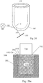
- Fig. 24 illustrates a sensor unit 100 with a double curved surface 107, e.g. the bottom of a vial, with a surface plasmon supporting conductive layer 110, where the surface plasmon can be excited in many directions.
- Fig 26a illustrates a sensor unit 100 with a flow structure 610 inserted in the optical substrate 103.
- the cavity that is formed between the substrate 103 and the flow structure 610 is filled with a sample 200.
- the molecular recognition sites 130 are placed on the surface plasmon supporting conductive layer 110 which is present at the concave surface of the wall of the substrate 103.
- the flow structure incorporates a temperature control unit 700 the purpose of which is to keep sample at sensor surface at a controlled temperature. Temperature can either be held constant or ramped.
- the thermo control unit consists basically of two parts, one sample temperature unit 710 which performs the local heat exchange at the sensor surface, and a heat/cold supplying unit 720, which supplies the sample temperature unit with heat or cold.
- the sample temperature unit 710 is in a simple embodiment, typically a piece of metal, and in a more advanced embodiment an insert made of e.g. polymers, ceramics, metal or a combination of these materials with channels for liquids carrying the heat flux.
- the heat/cold supplying unit is typical a thermoelectrical device (e.g. Peltier unit), but can also be a conventional compressor with heater/condenser or for the case only heating is necessary, a resistive element. Using a resistive element, the unit can be integrated with the sample temperature unit 710, forming a single unit. To obtain fast temperature ramps, different temperatures can be provided simultaneously at the heat/cold supplying unit 720, and these temperature stores can be switched into the sample control unit 710.
- a temperature control unit 700 where the sample temperature unit 710 and heat/cold supply unit 720 is separated by tubes, inlet and outlet carrying the liquid for thermal control.
- a temperature control unit 700 where the sample temperature unit 710 has two (or more) separated temperature zones creating a temperature gradient between them.
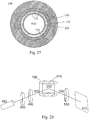
- Fig. 27 shows the sample temperature unit 710 inserted into the substrate 103, with the temperature controlling liquid 732 close to the sample 200, therefore obtaining fast and precise temperature control of the sample.
- Typical fixed temperatures are 25 and 37 degrees centigrade.
- Fig. 28 shows an ellipsomeric setup, i.e. measurement of the polarisation state.
- the light source 420 which can be monochromatic or multispectral, provides both p- and s- polarized light.
- This basic setup can be used for compensated as well as uncompensated ellipsometry.
- the uncompensated ellipsometer is shown as a PCSA-setup.
- the compensator 460 which is a quarter wave plate, is set to 45° to introduce a phase shift between the p- and s-polarized light.
- Both the polarizer 450 and analyzer 550 are rotated until the light at the detector 510 vanishes.
- the setup can also be used off-null, where both the analyzer 550 and polariser 450 are fixed at azimuths close to zero light at the detector 510.
- a rotating analyser ellipsometer, RAE is obtained for a fixed polarizer 450, usually at 45°, and a rotating analyzer 550.
- the compensator 460 is optional.
- the light source 410 and detector 510 can be used in imaging.
Landscapes
- Health & Medical Sciences (AREA)
- Immunology (AREA)
- Life Sciences & Earth Sciences (AREA)
- Chemical & Material Sciences (AREA)
- Pathology (AREA)
- General Physics & Mathematics (AREA)
- General Health & Medical Sciences (AREA)
- Biochemistry (AREA)
- Analytical Chemistry (AREA)
- Physics & Mathematics (AREA)
- Engineering & Computer Science (AREA)
- Urology & Nephrology (AREA)
- Molecular Biology (AREA)
- Hematology (AREA)
- Biomedical Technology (AREA)
- Food Science & Technology (AREA)
- Medicinal Chemistry (AREA)
- Microbiology (AREA)
- Cell Biology (AREA)
- Biotechnology (AREA)
- Investigating Or Analysing Materials By Optical Means (AREA)
Claims (15)
- Sensoreinheit (100) für eine Oberflächenplasmonresonanzeinheit, umfassend:- ein transparentes Sensorsubstrat (103), das zumindest eine Wand (103) eines Hohlraums bildet, wobei die Wand durch eine konkave Innenoberfläche und eine konvexe Außenoberfläche definiert ist; wobei- die Innenoberfläche mit einer Schicht (110) aus einem leitenden Material bereitgestellt ist, das dazu in der Lage ist, ein Oberflächenplasmon zu stützen;
wobei die Sensoreinheit dadurch gekennzeichnet ist, dass der Radius der konkaven Innenoberfläche größer als 3 mm und kleiner als 20 mm ist, und dass- die Sensoreinheit ferner eine Flussstruktur (600; 610; 620) in dem Hohlraum umfasst, um zumindest ein Kompartiment für eine Probe zwischen der Flussstruktur (600; 610; 620) und dem Substrat (103) des Hohlraums zu bilden, wobei die Flussstruktur (600; 610; 620) entwederwodurch die Höhe einer Flusszelle, die dadurch durch den Einsatz (610; 620) bereitgestellt wird, zwischen 10 und 100 Mikrometern ist, wobei die Flusszelle die Probenflussrate über die konkave Innenoberfläche kontrolliert.a. ein Pendelgewicht (600), das relativ zu der Innenoberfläche drehbar ist, oderb. ein Einsatz (610; 620) sein kann, der Nuten umfasst, die Kanäle (615; 625) bilden, wenn der Einsatz (610; 620) gegen die konkave Innenoberfläche der Wand anliegt, - Einheit nach Anspruch 1, wobei der Hohlraum durch eine Rohrleitung, eine Ampulle (107), ein längs geschnittenes Rohr, bevorzugt ein Halbrohr, oder eine Schale definiert ist.
- Einheit nach einem der Ansprüche 1-2, wobei die Sensoreinheit (100) hauptsächlich eine geschlossene Struktur ist, optional einen Boden und eine Kappe (190) aufweist, bevorzugt eine geschlossene Ampulle, eine geschlossene Schale oder ein geschlossener Behälter ist.
- Einheit nach einem der Ansprüche 1-3, wobei die Innenoberfläche und die Außenoberfläche unterschiedliche Radien an unterschiedlichen Positionen entlang der Höhe des Substrats (103) aufweisen.
- Einheit nach einem der Ansprüche 1-4, wobei die Schicht aus leitendem Material (110) mit einem oder einer Vielzahl von spezifischen oder nichtspezifischen Bereichen bedeckt ist, die Adsorptions- oder Reaktionsschicht/-schichten (130) für Moleküle oder Atome umfassen.
- Einheit nach einem der Ansprüche 1-5, wobei die Flussstruktur (610; 620) eine Vielzahl von Flusszellen in radialen (615), axialen (625) oder willkürlichen Richtungen in Bezug auf die Höhe des Substrats (103) der Sensoreinheit (100) einschließt.
- Einheit nach Anspruch 1, wobei der Abstand zwischen dem Pendelgewicht (600) und der Innenoberfläche entlang der Höhe des Substrats (103) variiert, um unterschiedliche Scherraten für Fluide zu erzeugen, wenn das Pendelgewicht (600) und die Sensoreinheit unterschiedliche Winkelgeschwindigkeit aufweisen.
- Einheit nach einem der Ansprüche 1-7, wobei die Flussstruktur (600; 610; 620) eine Probetemperatureinheit (710) einschließt, welche die Temperatur der Probe kontrolliert.
- Oberflächenplasmonvorrichtung, umfassenda) eine Lichtquelle (400);b) eine Sensoreinheit (100) nach einem der Ansprüche 1-8;c) einen Detektor (500) zum Erfassen von reflektiertem Licht (330) von der Sensoreinheit (100); undd) eine Verarbeitungseinheit (800).
- Vorrichtung nach Anspruch 9, ferner umfassend Mittel zum Kollimieren von Licht (300).
- Vorrichtung nach Anspruch 9 oder 10, wobei die Sensoreinheit (100) relativ zu der Lichtquelle (400) und dem Detektor drehbar ist, um unterschiedliche Sensorstellen (130) an der Sensoreinheit (100) zu positionieren, wobei die Lichtquelle (400) und der Detektor (500) relativ zu der Sensoreinheit drehbar sind.
- Vorrichtung nach einem der Ansprüche 9-11, wobei die Lichtquelle (400) entlang der Höhe des Substrats (103) der Sensoreinheit (100) bewegbar ist.
- Verfahren für die Erfassung von Ereignissen an einer Oberfläche durch Verwenden von Oberflächenplasmonresonanz, umfassend
Platzieren einer Probe mit einem Analyten von Interesse in einer Sensoreinheit (100) nach Anspruch 1;
Messen der Reflexion von der Sensoreinheit an einem Einzelwinkel oder an einer Vielzahl von Winkeln. - Verfahren nach Anspruch 13, wobei die Winkel die Winkel um den kritischen Winkel einschließen.
- Verfahren nach einem der Ansprüche 13-14, wobei die Änderung des Polarisationszustands der reflektierten Strahlung (330) bestimmt wird, d. h. durch eine ellipsometrische Messung.
Applications Claiming Priority (2)
| Application Number | Priority Date | Filing Date | Title |
|---|---|---|---|
| SE0602286A SE531493C2 (sv) | 2006-10-31 | 2006-10-31 | Sensor |
| PCT/SE2007/000950 WO2008054282A1 (en) | 2006-10-31 | 2007-10-29 | Sensor unit for a surface plasmon resonance (spr) unit |
Publications (3)
| Publication Number | Publication Date |
|---|---|
| EP2089692A1 EP2089692A1 (de) | 2009-08-19 |
| EP2089692A4 EP2089692A4 (de) | 2014-05-07 |
| EP2089692B1 true EP2089692B1 (de) | 2021-07-14 |
Family
ID=39344532
Family Applications (1)
| Application Number | Title | Priority Date | Filing Date |
|---|---|---|---|
| EP07835150.9A Active EP2089692B1 (de) | 2006-10-31 | 2007-10-29 | Sensoreinheit für eine spr- (surface plasmon resonance-)einheit |
Country Status (4)
| Country | Link |
|---|---|
| US (2) | US8149411B2 (de) |
| EP (1) | EP2089692B1 (de) |
| SE (1) | SE531493C2 (de) |
| WO (1) | WO2008054282A1 (de) |
Families Citing this family (22)
| Publication number | Priority date | Publication date | Assignee | Title |
|---|---|---|---|---|
| US7463358B2 (en) * | 2005-12-06 | 2008-12-09 | Lumera Corporation | Highly stable surface plasmon resonance plates, microarrays, and methods |
| ES2334318B2 (es) | 2008-09-05 | 2011-11-28 | Universidad Politécnica de Madrid | Sistema de deteccion optica para bio-ensayos de alta sensibilidad sinmarcado. |
| TWI383139B (zh) * | 2008-11-20 | 2013-01-21 | 國立中正大學 | Tubular waveguide type plasma resonance sensing device and sensing system |
| KR101012056B1 (ko) * | 2008-11-28 | 2011-02-01 | 한국표준과학연구원 | 다채널 타원계측 표면 플라즈몬 공명 측정장치 |
| TWI399532B (zh) * | 2009-01-20 | 2013-06-21 | Nat Chung Cheng University Inv | Optical fiber type localized plasma resonance sensing device and its system |
| WO2010128395A1 (en) * | 2009-05-04 | 2010-11-11 | Theodore Peter Rakitzis | Intra-cavity ellipsometer system and method |
| US8696991B1 (en) | 2010-01-04 | 2014-04-15 | Harold W. Howe | Field deployable surface plasmon resonance based biosensor |
| US9116122B2 (en) * | 2011-06-06 | 2015-08-25 | The United States Of America As Represented By The Secretary Of The Navy | Surface plasmon resonance biosensor |
| FR2982027B1 (fr) * | 2011-10-26 | 2014-01-03 | Thibaut Mercey | Puce microstructuree pour analyse par resonance des plasmons de surface, dispositif d'analyse comprenant ladite puce microstructuree et utilisation dudit dispositif |
| CN102608075A (zh) * | 2012-04-05 | 2012-07-25 | 浙江大学 | 一种毛细管表面等离子共振传感器 |
| EP2859325A2 (de) | 2012-06-10 | 2015-04-15 | Bio-Rad Laboratories, Inc. | Optisches detektionssystem für flüssigkeitsproben |
| JP5941220B2 (ja) * | 2013-05-23 | 2016-06-29 | 日本電信電話株式会社 | 血液凝固検査方法 |
| CN105823474B (zh) * | 2016-03-21 | 2018-06-19 | 东南大学 | 基于可调谐表面等离激元耦合器的光纤陀螺谐振腔芯片 |
| WO2018105975A1 (ko) * | 2016-12-05 | 2018-06-14 | 엘지이노텍 주식회사 | 반도체 소자, 반도체 소자 제조방법 및 감지 장치 |
| US10901228B2 (en) * | 2017-06-27 | 2021-01-26 | The Boeing Company | Cavity with curved beam replicator and method of determining a characteristic of a medium therein |
| AT520258B1 (de) * | 2017-07-26 | 2022-02-15 | Univ Wien Tech | Verfahren zur spektroskopischen bzw. spektrometrischen Untersuchung einer Probe |
| CN108090891B (zh) * | 2017-11-01 | 2020-10-30 | 浙江农林大学 | 一种检测遗漏细胞区域与新增细胞区域的方法及系统 |
| EP3537100B1 (de) * | 2018-03-01 | 2020-08-05 | Mitutoyo Corporation | Verfahren und vorrichtungen zur brechungsindexmessung eines transparenten rohrs |
| JP7482887B2 (ja) * | 2019-09-24 | 2024-05-14 | 大塚製薬株式会社 | 検出方法および検出装置 |
| KR102267315B1 (ko) * | 2019-12-03 | 2021-06-18 | 고려대학교 산학협력단 | 시료의 입자 크기 측정용 장치 |
| US11245044B2 (en) * | 2020-01-14 | 2022-02-08 | Hoon Kim | Plasmonic field-enhanced photodetector and image sensor |
| CN114235754A (zh) * | 2021-12-18 | 2022-03-25 | 桂林电子科技大学 | 一种基于毛细管的带有温度补偿的光纤spr传感器 |
Citations (2)
| Publication number | Priority date | Publication date | Assignee | Title |
|---|---|---|---|---|
| US3027799A (en) * | 1959-01-26 | 1962-04-03 | Brunswick Corp | Sample space adapters for spectrophotometers and the like |
| WO1998054475A1 (en) * | 1997-05-26 | 1998-12-03 | Global Hemostasis Institute Mgr | Bearing device |
Family Cites Families (23)
| Publication number | Priority date | Publication date | Assignee | Title |
|---|---|---|---|---|
| DE4016617A1 (de) * | 1990-05-23 | 1991-11-28 | Rainer Dylla | Objekttraeger fuer nasse oder feuchte praeparate, z. b. blut |
| US5257093A (en) * | 1991-11-12 | 1993-10-26 | Guziktechnical Enterprises, Inc. | Apparatus for measuring nanometric distances employing frustrated total internal reflection |
| US5593558A (en) * | 1994-06-09 | 1997-01-14 | Nippondenso Co., Ltd. | Oxygen concentration detector |
| US6486947B2 (en) * | 1998-07-22 | 2002-11-26 | Ljl Biosystems, Inc. | Devices and methods for sample analysis |
| US6480282B1 (en) * | 1999-05-06 | 2002-11-12 | University Of Washington | Capillary surface plasmon resonance sensors and multisensors |
| US7523415B1 (en) * | 1999-06-24 | 2009-04-21 | Porter Swain W | Exclusive use display surface areas and persistently visible display of contents including advertisements |
| ATE353438T1 (de) * | 2000-02-22 | 2007-02-15 | Santhera Pharmaceuticals Deuts | Spr-sensorsystem |
| DE10012793C2 (de) * | 2000-03-13 | 2002-01-24 | Fraunhofer Ges Forschung | Sensorelement zur optischen Detektion von chemischen oder biochemischen Analyten |
| US6864984B2 (en) | 2000-03-16 | 2005-03-08 | Fuji Photo Film Co., Ltd. | Measuring method and apparatus using attenuation in total reflection |
| DE10019359C2 (de) * | 2000-04-18 | 2002-11-07 | Nanofilm Technologie Gmbh | SPR-Sensor |
| US7998746B2 (en) * | 2000-08-24 | 2011-08-16 | Robert Otillar | Systems and methods for localizing and analyzing samples on a bio-sensor chip |
| JP2003075333A (ja) * | 2001-08-31 | 2003-03-12 | Mitsubishi Heavy Ind Ltd | 表面プラズモン共鳴センサ装置 |
| WO2003031163A2 (en) * | 2001-10-08 | 2003-04-17 | California Institute Of Technology | Microfabricated lenses, methods of manufacture thereof, and applications therefor |
| JP2003294615A (ja) * | 2002-03-29 | 2003-10-15 | Toppan Printing Co Ltd | 表面プラズモン素子及びこれを用いた物質検査装置 |
| EP1445601A3 (de) * | 2003-01-30 | 2004-09-22 | Fuji Photo Film Co., Ltd. | Messchips für lokale Oberflächenplasmonenresonanzmesssensoren, Herstellungsverfahren für diese Messchips und Sensoren welche diese Chips verwenden |
| US7276351B2 (en) * | 2003-09-10 | 2007-10-02 | Seahorse Bioscience | Method and device for measuring multiple physiological properties of cells |
| JP4579593B2 (ja) * | 2004-03-05 | 2010-11-10 | キヤノン株式会社 | 標的物質認識素子、検出方法及び装置 |
| JP4548416B2 (ja) * | 2004-03-31 | 2010-09-22 | オムロン株式会社 | 局在プラズモン共鳴センサ及び検査装置 |
| DE102005004640B4 (de) * | 2005-01-28 | 2009-01-29 | Cross Match Technologies Gmbh | Anordnung zur optoelektronischen Aufnahme von großflächigen Fingerabdrücken |
| JP4118901B2 (ja) * | 2005-07-13 | 2008-07-16 | 株式会社日立製作所 | マイクロ計測器 |
| DE102005054495A1 (de) * | 2005-11-16 | 2007-05-24 | Mivitec Gmbh | Verteilte Sensor- und Referenzspots für Chemo- und Biosensoren |
| KR20080082976A (ko) * | 2005-12-16 | 2008-09-12 | 인디애나 유니버시티 리서치 앤드 테크놀로지 코포레이션 | 서브-미크론 표면 플라즈몬 공진 센서 시스템들 |
| US7835013B2 (en) * | 2007-05-18 | 2010-11-16 | Vanderbilt University | Interferometric detection system and method |
-
2006
- 2006-10-31 SE SE0602286A patent/SE531493C2/sv unknown
-
2007
- 2007-10-29 EP EP07835150.9A patent/EP2089692B1/de active Active
- 2007-10-29 WO PCT/SE2007/000950 patent/WO2008054282A1/en not_active Ceased
- 2007-10-29 US US12/447,825 patent/US8149411B2/en active Active
-
2012
- 2012-03-14 US US13/420,185 patent/US8243277B2/en not_active Expired - Fee Related
Patent Citations (2)
| Publication number | Priority date | Publication date | Assignee | Title |
|---|---|---|---|---|
| US3027799A (en) * | 1959-01-26 | 1962-04-03 | Brunswick Corp | Sample space adapters for spectrophotometers and the like |
| WO1998054475A1 (en) * | 1997-05-26 | 1998-12-03 | Global Hemostasis Institute Mgr | Bearing device |
Non-Patent Citations (1)
| Title |
|---|
| KENNY M HANSSON ET AL: "Surface plasmon resonance and free oscillation rheometry in combination: a useful approach for studies on haemostasis and interactions between whole blood and artificial surfaces", BIOSENSORS AND BIOELECTRONICS, vol. 17, no. 9, 1 September 2002 (2002-09-01), NL, pages 747 - 759, XP055474453, ISSN: 0956-5663, DOI: 10.1016/S0956-5663(02)00048-9 * |
Also Published As
| Publication number | Publication date |
|---|---|
| US8149411B2 (en) | 2012-04-03 |
| EP2089692A1 (de) | 2009-08-19 |
| US20120170036A1 (en) | 2012-07-05 |
| SE531493C2 (sv) | 2009-04-28 |
| US8243277B2 (en) | 2012-08-14 |
| US20100103421A1 (en) | 2010-04-29 |
| WO2008054282A1 (en) | 2008-05-08 |
| WO2008054282A8 (en) | 2009-06-04 |
| SE0602286L (sv) | 2008-05-01 |
| EP2089692A4 (de) | 2014-05-07 |
Similar Documents
| Publication | Publication Date | Title |
|---|---|---|
| EP2089692B1 (de) | Sensoreinheit für eine spr- (surface plasmon resonance-)einheit | |
| US6862094B2 (en) | Imaging SPR apparatus | |
| US20030175160A1 (en) | High throughput screening with parallel vibrational spectroscopy | |
| US20050214167A1 (en) | High throughput screening with parallel vibrational spectroscopy | |
| US8021613B2 (en) | System and method for self-referencing a sensor in a micron-sized deep flow chamber | |
| US8330959B2 (en) | Multi-channel surface plasmon resonance instrument | |
| CN101147049A (zh) | 成像方法和装置 | |
| US20020149775A1 (en) | Measuring sensor utilizing attenuated total reflection and measuring chip assembly | |
| US8743367B2 (en) | Optical resonance analysis using a multi-angle source of illumination | |
| CN104081187B (zh) | 微结构化芯片,包含微结构化芯片的分析装置及该装置的用途 | |
| JPH06500636A (ja) | 化学、生化学および生物学的な測定試料の特異物質を選択的に検出する光学的な方法 | |
| Jorgenson | A surface plasmon resonance side active retro-reflecting sensor | |
| CN104105956B (zh) | 用于表面等离子体共振分析的微结构化芯片,包含所述微结构化芯片的分析装置和所述装置的使用 | |
| EP1733207A1 (de) | Ellipsometrischer biosensor mit verstärkerschicht | |
| Han et al. | An ellipsometric surface plasmon resonance system for quantitatively determining the normal of a sensor surface and multi-channel measurement | |
| JP3716305B2 (ja) | 内部反射型二次元イメージングエリプソメータ | |
| JP2004531719A (ja) | イメージングの装置及び方法 | |
| US7349092B1 (en) | System for reducing stress induced effects during determination of fluid optical constants | |
| KR100820235B1 (ko) | 다 매질에서 측정 가능한 광학계를 이용한 표면 플라즈몬공명 장치 | |
| Jin | Development of biosensor based on imaging ellipsometry and its applications | |
| Widjaja | Surface Plasmon Resonance | |
| JP2002148186A (ja) | 偏光測定方法および装置 | |
| Yuan et al. | RESEARCH ON WATER QUALITY TESTS BASED ON OPTICAL WAVEGUIDE SURFACE PLASMON RESONANCE TECHNOLOGY | |
| JP2002174590A (ja) | 光学検出装置 |
Legal Events
| Date | Code | Title | Description |
|---|---|---|---|
| PUAI | Public reference made under article 153(3) epc to a published international application that has entered the european phase |
Free format text: ORIGINAL CODE: 0009012 |
|
| 17P | Request for examination filed |
Effective date: 20090529 |
|
| AK | Designated contracting states |
Kind code of ref document: A1 Designated state(s): AT BE BG CH CY CZ DE DK EE ES FI FR GB GR HU IE IS IT LI LT LU LV MC MT NL PL PT RO SE SI SK TR |
|
| DAX | Request for extension of the european patent (deleted) | ||
| A4 | Supplementary search report drawn up and despatched |
Effective date: 20140409 |
|
| RIC1 | Information provided on ipc code assigned before grant |
Ipc: G01N 21/55 20140101AFI20140403BHEP Ipc: G01N 21/03 20060101ALI20140403BHEP Ipc: G01N 33/543 20060101ALI20140403BHEP |
|
| 17Q | First examination report despatched |
Effective date: 20140602 |
|
| STAA | Information on the status of an ep patent application or granted ep patent |
Free format text: STATUS: EXAMINATION IS IN PROGRESS |
|
| GRAP | Despatch of communication of intention to grant a patent |
Free format text: ORIGINAL CODE: EPIDOSNIGR1 |
|
| STAA | Information on the status of an ep patent application or granted ep patent |
Free format text: STATUS: GRANT OF PATENT IS INTENDED |
|
| RIN1 | Information on inventor provided before grant (corrected) |
Inventor name: JOHANSEN, KNUT Inventor name: RANBY, MATS |
|
| INTG | Intention to grant announced |
Effective date: 20210216 |
|
| GRAS | Grant fee paid |
Free format text: ORIGINAL CODE: EPIDOSNIGR3 |
|
| GRAA | (expected) grant |
Free format text: ORIGINAL CODE: 0009210 |
|
| STAA | Information on the status of an ep patent application or granted ep patent |
Free format text: STATUS: THE PATENT HAS BEEN GRANTED |
|
| AK | Designated contracting states |
Kind code of ref document: B1 Designated state(s): AT BE BG CH CY CZ DE DK EE ES FI FR GB GR HU IE IS IT LI LT LU LV MC MT NL PL PT RO SE SI SK TR |
|
| REG | Reference to a national code |
Ref country code: GB Ref legal event code: FG4D |
|
| REG | Reference to a national code |
Ref country code: IE Ref legal event code: FG4D |
|
| REG | Reference to a national code |
Ref country code: DE Ref legal event code: R096 Ref document number: 602007061227 Country of ref document: DE |
|
| REG | Reference to a national code |
Ref country code: AT Ref legal event code: REF Ref document number: 1411047 Country of ref document: AT Kind code of ref document: T Effective date: 20210815 |
|
| REG | Reference to a national code |
Ref country code: LT Ref legal event code: MG9D |
|
| REG | Reference to a national code |
Ref country code: NL Ref legal event code: MP Effective date: 20210714 |
|
| REG | Reference to a national code |
Ref country code: AT Ref legal event code: MK05 Ref document number: 1411047 Country of ref document: AT Kind code of ref document: T Effective date: 20210714 |
|
| PG25 | Lapsed in a contracting state [announced via postgrant information from national office to epo] |
Ref country code: LT Free format text: LAPSE BECAUSE OF FAILURE TO SUBMIT A TRANSLATION OF THE DESCRIPTION OR TO PAY THE FEE WITHIN THE PRESCRIBED TIME-LIMIT Effective date: 20210714 Ref country code: BG Free format text: LAPSE BECAUSE OF FAILURE TO SUBMIT A TRANSLATION OF THE DESCRIPTION OR TO PAY THE FEE WITHIN THE PRESCRIBED TIME-LIMIT Effective date: 20211014 Ref country code: AT Free format text: LAPSE BECAUSE OF FAILURE TO SUBMIT A TRANSLATION OF THE DESCRIPTION OR TO PAY THE FEE WITHIN THE PRESCRIBED TIME-LIMIT Effective date: 20210714 Ref country code: ES Free format text: LAPSE BECAUSE OF FAILURE TO SUBMIT A TRANSLATION OF THE DESCRIPTION OR TO PAY THE FEE WITHIN THE PRESCRIBED TIME-LIMIT Effective date: 20210714 Ref country code: FI Free format text: LAPSE BECAUSE OF FAILURE TO SUBMIT A TRANSLATION OF THE DESCRIPTION OR TO PAY THE FEE WITHIN THE PRESCRIBED TIME-LIMIT Effective date: 20210714 Ref country code: NL Free format text: LAPSE BECAUSE OF FAILURE TO SUBMIT A TRANSLATION OF THE DESCRIPTION OR TO PAY THE FEE WITHIN THE PRESCRIBED TIME-LIMIT Effective date: 20210714 Ref country code: PT Free format text: LAPSE BECAUSE OF FAILURE TO SUBMIT A TRANSLATION OF THE DESCRIPTION OR TO PAY THE FEE WITHIN THE PRESCRIBED TIME-LIMIT Effective date: 20211115 Ref country code: SE Free format text: LAPSE BECAUSE OF FAILURE TO SUBMIT A TRANSLATION OF THE DESCRIPTION OR TO PAY THE FEE WITHIN THE PRESCRIBED TIME-LIMIT Effective date: 20210714 |
|
| PG25 | Lapsed in a contracting state [announced via postgrant information from national office to epo] |
Ref country code: PL Free format text: LAPSE BECAUSE OF FAILURE TO SUBMIT A TRANSLATION OF THE DESCRIPTION OR TO PAY THE FEE WITHIN THE PRESCRIBED TIME-LIMIT Effective date: 20210714 Ref country code: LV Free format text: LAPSE BECAUSE OF FAILURE TO SUBMIT A TRANSLATION OF THE DESCRIPTION OR TO PAY THE FEE WITHIN THE PRESCRIBED TIME-LIMIT Effective date: 20210714 Ref country code: GR Free format text: LAPSE BECAUSE OF FAILURE TO SUBMIT A TRANSLATION OF THE DESCRIPTION OR TO PAY THE FEE WITHIN THE PRESCRIBED TIME-LIMIT Effective date: 20211015 |
|
| REG | Reference to a national code |
Ref country code: DE Ref legal event code: R097 Ref document number: 602007061227 Country of ref document: DE |
|
| PG25 | Lapsed in a contracting state [announced via postgrant information from national office to epo] |
Ref country code: DK Free format text: LAPSE BECAUSE OF FAILURE TO SUBMIT A TRANSLATION OF THE DESCRIPTION OR TO PAY THE FEE WITHIN THE PRESCRIBED TIME-LIMIT Effective date: 20210714 |
|
| PLBE | No opposition filed within time limit |
Free format text: ORIGINAL CODE: 0009261 |
|
| STAA | Information on the status of an ep patent application or granted ep patent |
Free format text: STATUS: NO OPPOSITION FILED WITHIN TIME LIMIT |
|
| REG | Reference to a national code |
Ref country code: CH Ref legal event code: PL |
|
| PG25 | Lapsed in a contracting state [announced via postgrant information from national office to epo] |
Ref country code: SK Free format text: LAPSE BECAUSE OF FAILURE TO SUBMIT A TRANSLATION OF THE DESCRIPTION OR TO PAY THE FEE WITHIN THE PRESCRIBED TIME-LIMIT Effective date: 20210714 Ref country code: RO Free format text: LAPSE BECAUSE OF FAILURE TO SUBMIT A TRANSLATION OF THE DESCRIPTION OR TO PAY THE FEE WITHIN THE PRESCRIBED TIME-LIMIT Effective date: 20210714 Ref country code: EE Free format text: LAPSE BECAUSE OF FAILURE TO SUBMIT A TRANSLATION OF THE DESCRIPTION OR TO PAY THE FEE WITHIN THE PRESCRIBED TIME-LIMIT Effective date: 20210714 Ref country code: CZ Free format text: LAPSE BECAUSE OF FAILURE TO SUBMIT A TRANSLATION OF THE DESCRIPTION OR TO PAY THE FEE WITHIN THE PRESCRIBED TIME-LIMIT Effective date: 20210714 |
|
| 26N | No opposition filed |
Effective date: 20220419 |
|
| REG | Reference to a national code |
Ref country code: BE Ref legal event code: MM Effective date: 20211031 |
|
| PG25 | Lapsed in a contracting state [announced via postgrant information from national office to epo] |
Ref country code: MC Free format text: LAPSE BECAUSE OF FAILURE TO SUBMIT A TRANSLATION OF THE DESCRIPTION OR TO PAY THE FEE WITHIN THE PRESCRIBED TIME-LIMIT Effective date: 20210714 |
|
| PG25 | Lapsed in a contracting state [announced via postgrant information from national office to epo] |
Ref country code: LU Free format text: LAPSE BECAUSE OF NON-PAYMENT OF DUE FEES Effective date: 20211029 Ref country code: IT Free format text: LAPSE BECAUSE OF FAILURE TO SUBMIT A TRANSLATION OF THE DESCRIPTION OR TO PAY THE FEE WITHIN THE PRESCRIBED TIME-LIMIT Effective date: 20210714 Ref country code: BE Free format text: LAPSE BECAUSE OF NON-PAYMENT OF DUE FEES Effective date: 20211031 |
|
| PG25 | Lapsed in a contracting state [announced via postgrant information from national office to epo] |
Ref country code: LI Free format text: LAPSE BECAUSE OF NON-PAYMENT OF DUE FEES Effective date: 20211031 Ref country code: CH Free format text: LAPSE BECAUSE OF NON-PAYMENT OF DUE FEES Effective date: 20211031 |
|
| PG25 | Lapsed in a contracting state [announced via postgrant information from national office to epo] |
Ref country code: IE Free format text: LAPSE BECAUSE OF NON-PAYMENT OF DUE FEES Effective date: 20211029 |
|
| PGFP | Annual fee paid to national office [announced via postgrant information from national office to epo] |
Ref country code: FR Payment date: 20221030 Year of fee payment: 16 |
|
| PG25 | Lapsed in a contracting state [announced via postgrant information from national office to epo] |
Ref country code: HU Free format text: LAPSE BECAUSE OF FAILURE TO SUBMIT A TRANSLATION OF THE DESCRIPTION OR TO PAY THE FEE WITHIN THE PRESCRIBED TIME-LIMIT; INVALID AB INITIO Effective date: 20071029 Ref country code: CY Free format text: LAPSE BECAUSE OF FAILURE TO SUBMIT A TRANSLATION OF THE DESCRIPTION OR TO PAY THE FEE WITHIN THE PRESCRIBED TIME-LIMIT Effective date: 20210714 |
|
| P01 | Opt-out of the competence of the unified patent court (upc) registered |
Effective date: 20230428 |
|
| PGFP | Annual fee paid to national office [announced via postgrant information from national office to epo] |
Ref country code: DE Payment date: 20230427 Year of fee payment: 16 |
|
| REG | Reference to a national code |
Ref country code: DE Ref legal event code: R119 Ref document number: 602007061227 Country of ref document: DE |
|
| PG25 | Lapsed in a contracting state [announced via postgrant information from national office to epo] |
Ref country code: TR Free format text: LAPSE BECAUSE OF FAILURE TO SUBMIT A TRANSLATION OF THE DESCRIPTION OR TO PAY THE FEE WITHIN THE PRESCRIBED TIME-LIMIT Effective date: 20210714 |
|
| PG25 | Lapsed in a contracting state [announced via postgrant information from national office to epo] |
Ref country code: FR Free format text: LAPSE BECAUSE OF NON-PAYMENT OF DUE FEES Effective date: 20231031 Ref country code: DE Free format text: LAPSE BECAUSE OF NON-PAYMENT OF DUE FEES Effective date: 20240501 |
|
| PG25 | Lapsed in a contracting state [announced via postgrant information from national office to epo] |
Ref country code: MT Free format text: LAPSE BECAUSE OF FAILURE TO SUBMIT A TRANSLATION OF THE DESCRIPTION OR TO PAY THE FEE WITHIN THE PRESCRIBED TIME-LIMIT Effective date: 20210714 |
|
| PGFP | Annual fee paid to national office [announced via postgrant information from national office to epo] |
Ref country code: GB Payment date: 20241129 Year of fee payment: 18 |