EP2089656B2 - Verfahren und Vorrichtung zum Bereitstellen einer gleichmässigen Projektionsbeleuchtung - Google Patents
Verfahren und Vorrichtung zum Bereitstellen einer gleichmässigen Projektionsbeleuchtung Download PDFInfo
- Publication number
- EP2089656B2 EP2089656B2 EP07862228.9A EP07862228A EP2089656B2 EP 2089656 B2 EP2089656 B2 EP 2089656B2 EP 07862228 A EP07862228 A EP 07862228A EP 2089656 B2 EP2089656 B2 EP 2089656B2
- Authority
- EP
- European Patent Office
- Prior art keywords
- light source
- led
- light
- reference axis
- orientation
- Prior art date
- Legal status (The legal status is an assumption and is not a legal conclusion. Google has not performed a legal analysis and makes no representation as to the accuracy of the status listed.)
- Active
Links
Images


Classifications
-
- F—MECHANICAL ENGINEERING; LIGHTING; HEATING; WEAPONS; BLASTING
- F21—LIGHTING
- F21V—FUNCTIONAL FEATURES OR DETAILS OF LIGHTING DEVICES OR SYSTEMS THEREOF; STRUCTURAL COMBINATIONS OF LIGHTING DEVICES WITH OTHER ARTICLES, NOT OTHERWISE PROVIDED FOR
- F21V7/00—Reflectors for light sources
- F21V7/0091—Reflectors for light sources using total internal reflection
-
- G—PHYSICS
- G03—PHOTOGRAPHY; CINEMATOGRAPHY; ANALOGOUS TECHNIQUES USING WAVES OTHER THAN OPTICAL WAVES; ELECTROGRAPHY; HOLOGRAPHY
- G03B—APPARATUS OR ARRANGEMENTS FOR TAKING PHOTOGRAPHS OR FOR PROJECTING OR VIEWING THEM; APPARATUS OR ARRANGEMENTS EMPLOYING ANALOGOUS TECHNIQUES USING WAVES OTHER THAN OPTICAL WAVES; ACCESSORIES THEREFOR
- G03B21/00—Projectors or projection-type viewers; Accessories therefor
- G03B21/14—Details
- G03B21/20—Lamp housings
- G03B21/2006—Lamp housings characterised by the light source
- G03B21/2013—Plural light sources
-
- G—PHYSICS
- G03—PHOTOGRAPHY; CINEMATOGRAPHY; ANALOGOUS TECHNIQUES USING WAVES OTHER THAN OPTICAL WAVES; ELECTROGRAPHY; HOLOGRAPHY
- G03B—APPARATUS OR ARRANGEMENTS FOR TAKING PHOTOGRAPHS OR FOR PROJECTING OR VIEWING THEM; APPARATUS OR ARRANGEMENTS EMPLOYING ANALOGOUS TECHNIQUES USING WAVES OTHER THAN OPTICAL WAVES; ACCESSORIES THEREFOR
- G03B21/00—Projectors or projection-type viewers; Accessories therefor
- G03B21/14—Details
- G03B21/20—Lamp housings
- G03B21/2006—Lamp housings characterised by the light source
- G03B21/2033—LED or laser light sources
-
- G—PHYSICS
- G03—PHOTOGRAPHY; CINEMATOGRAPHY; ANALOGOUS TECHNIQUES USING WAVES OTHER THAN OPTICAL WAVES; ELECTROGRAPHY; HOLOGRAPHY
- G03B—APPARATUS OR ARRANGEMENTS FOR TAKING PHOTOGRAPHS OR FOR PROJECTING OR VIEWING THEM; APPARATUS OR ARRANGEMENTS EMPLOYING ANALOGOUS TECHNIQUES USING WAVES OTHER THAN OPTICAL WAVES; ACCESSORIES THEREFOR
- G03B21/00—Projectors or projection-type viewers; Accessories therefor
- G03B21/14—Details
- G03B21/20—Lamp housings
- G03B21/208—Homogenising, shaping of the illumination light
-
- F—MECHANICAL ENGINEERING; LIGHTING; HEATING; WEAPONS; BLASTING
- F21—LIGHTING
- F21K—NON-ELECTRIC LIGHT SOURCES USING LUMINESCENCE; LIGHT SOURCES USING ELECTROCHEMILUMINESCENCE; LIGHT SOURCES USING CHARGES OF COMBUSTIBLE MATERIAL; LIGHT SOURCES USING SEMICONDUCTOR DEVICES AS LIGHT-GENERATING ELEMENTS; LIGHT SOURCES NOT OTHERWISE PROVIDED FOR
- F21K9/00—Light sources using semiconductor devices as light-generating elements, e.g. using light-emitting diodes [LED] or lasers
- F21K9/20—Light sources comprising attachment means
- F21K9/23—Retrofit light sources for lighting devices with a single fitting for each light source, e.g. for substitution of incandescent lamps with bayonet or threaded fittings
- F21K9/233—Retrofit light sources for lighting devices with a single fitting for each light source, e.g. for substitution of incandescent lamps with bayonet or threaded fittings specially adapted for generating a spot light distribution, e.g. for substitution of reflector lamps
-
- F—MECHANICAL ENGINEERING; LIGHTING; HEATING; WEAPONS; BLASTING
- F21—LIGHTING
- F21Y—INDEXING SCHEME ASSOCIATED WITH SUBCLASSES F21K, F21L, F21S and F21V, RELATING TO THE FORM OR THE KIND OF THE LIGHT SOURCES OR OF THE COLOUR OF THE LIGHT EMITTED
- F21Y2105/00—Planar light sources
- F21Y2105/10—Planar light sources comprising a two-dimensional [2D] array of point-like light-generating elements
- F21Y2105/12—Planar light sources comprising a two-dimensional [2D] array of point-like light-generating elements characterised by the geometrical disposition of the light-generating elements, e.g. arranging light-generating elements in differing patterns or densities
-
- F—MECHANICAL ENGINEERING; LIGHTING; HEATING; WEAPONS; BLASTING
- F21—LIGHTING
- F21Y—INDEXING SCHEME ASSOCIATED WITH SUBCLASSES F21K, F21L, F21S and F21V, RELATING TO THE FORM OR THE KIND OF THE LIGHT SOURCES OR OF THE COLOUR OF THE LIGHT EMITTED
- F21Y2113/00—Combination of light sources
- F21Y2113/10—Combination of light sources of different colours
- F21Y2113/13—Combination of light sources of different colours comprising an assembly of point-like light sources
- F21Y2113/17—Combination of light sources of different colours comprising an assembly of point-like light sources forming a single encapsulated light source
-
- F—MECHANICAL ENGINEERING; LIGHTING; HEATING; WEAPONS; BLASTING
- F21—LIGHTING
- F21Y—INDEXING SCHEME ASSOCIATED WITH SUBCLASSES F21K, F21L, F21S and F21V, RELATING TO THE FORM OR THE KIND OF THE LIGHT SOURCES OR OF THE COLOUR OF THE LIGHT EMITTED
- F21Y2115/00—Light-generating elements of semiconductor light sources
- F21Y2115/10—Light-emitting diodes [LED]
-
- Y—GENERAL TAGGING OF NEW TECHNOLOGICAL DEVELOPMENTS; GENERAL TAGGING OF CROSS-SECTIONAL TECHNOLOGIES SPANNING OVER SEVERAL SECTIONS OF THE IPC; TECHNICAL SUBJECTS COVERED BY FORMER USPC CROSS-REFERENCE ART COLLECTIONS [XRACs] AND DIGESTS
- Y10—TECHNICAL SUBJECTS COVERED BY FORMER USPC
- Y10S—TECHNICAL SUBJECTS COVERED BY FORMER USPC CROSS-REFERENCE ART COLLECTIONS [XRACs] AND DIGESTS
- Y10S362/00—Illumination
- Y10S362/80—Light emitting diode
Definitions
- the present invention generally relates to projection lighting fixtures and methods for arranging light sources and optical structures within such fixtures to provide substantially uniform projection lighting.
- Projection lighting fixtures concentrate light in a specific direction. These fixtures have been used for many years in various theater, television, architectural, and general illumination applications (e.g., overhead projection, spotlight illumination, semiconductor assembly, medical/scientific instrumentation, illumination of airport runways and high-rise buildings, etc.). Typically, these fixtures include an incandescent or a gas-discharge lamp mounted adjacent to a concave reflector, which reflects light through a lens assembly to project a narrow beam of light over considerable distance towards a target object.
- incandescent or a gas-discharge lamp mounted adjacent to a concave reflector, which reflects light through a lens assembly to project a narrow beam of light over considerable distance towards a target object.
- a "chip-on-board” (COB) LED assembly refers generally to one or more semiconductor chips (or “dies”) in which one or more LED junctions are fabricated, wherein the chip(s) is/are mounted (e.g., adhered) directly to a printed circuit board (PCB).
- PCB printed circuit board
- the chip(s) is/are then wire bonded to the PCB, after which a glob of epoxy or plastic may be used to cover the chip(s) and wire connections.
- a glob of epoxy or plastic may be used to cover the chip(s) and wire connections.
- LED assemblies, or "LED packages,” in turn may be mounted to a common mounting board or substrate of a lighting fixture.
- TIR collimator lenses For some narrow-beam applications involving LED chips or dies, optical elements may be used together with the LED chip-on-board assembly to facilitate focusing of the generated light to create a narrow-beam of collimated light.
- Collimated light is light whose rays are parallel and thus has a planar wavefront.
- Optical structures for collimating visible light often referred to as “collimator lenses” or “collimators,” are known in the art. These structures capture and redirect light emitted by a light source to improve its directionality.
- One such collimator is a total internal reflection ("TIR") collimator.
- TIR collimator includes a reflective inner surface that is positioned to capture much of the light emitted by a light source subtended by the collimator.
- the reflective surface of conventional TIR collimators is typically conical, that is, derived from a parabolic, elliptical, or hyperbolic curve.
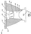
- a conventional TIR collimator 100 collects the light emitted by an LED light source 112 (which may include an LED chip-on-board assembly, or "LED package,” including one or more LED junctions) and directs the light so that it exits the collimator at a top portion 113. Some of the light travels from source 112 through a primary optic 114, into a first cavity 116, through a centrally-located lens 118, and out via a second cavity 120. The remainder of the light exits via a transparent surface 122 or a flange 124, which is used to retain collimator 100 in a holder (not shown).
- LED light source 112 which may include an LED chip-on-board assembly, or "LED package,” including one or more LED junctions
- the light that does not pass through the central lens is incident on an inner sidewall 126 and is refracted as it passes from the air in the first cavity into the plastic material of the collimator. Thereafter, it is reflected at an inner reflective surface 129. The reflected light is refracted again as it travels from the plastic body of the collimator to the ambient air, at transparent surface 122.
- the reflective surface is conical, so that a cross-sectional profile of the collimator is parabolic at the reflective surface, as shown in FIG. 1 .
- the reflection at reflective surface 129 occurs by total internal reflection, establishing constraints on the overall shape and curvature of the cross-sectional profile of the reflective surface. Due to the difference between the refractive index of collimator 100 and the refractive index of the ambient air, Snell's law applies and defines a critical angle for the angle of incidence, which is made by an incident light ray with respect to a normal to the reflective surface. That is, for incident angles above the critical angle, all of the light is reflected and none is transmitted through the reflective surface 129 or along the surface 129, thereby providing total internal reflection. For a plastic (refractive index of about 1.59)-air (refractive index of 1) interface, the critical angle is about 39 degrees. Thus, the reflective surface 129 is sloped to provide an angle of incidence for most of the light that is greater than about 39 degrees.
- conventional collimators are capable of producing perfectly collimated light from an ideal point source at the focus.
- a light source of an appreciable surface area such as an LED light source
- the light is not completely collimated, but rather is directed into a diverging conic beam.
- the light output from a conventional LED source e.g., a COB LED assembly
- a collimator similar to that shown in FIG. 1 may redirect the generated light into a narrower cone-shaped beam having a divergence of approximately 10 degrees (i.e., approximately 5 degrees to either side of the central axis).
- the phenomenon of chip or die imaging may be problematic.
- the generally square or rectangular shape of the light emitting portion of an LED package i.e., the arrangement of one or more chips in the package
- the square or rectangular shape of the light emitting portion of the LED package may be "imaged" in the far field due to collimation, which may result in undesirable irradiation non-uniformity in some circumstances.
- LED packages including multiple junctions that generate respective different wavelenghts of light
- multi-color packages such as RGGB, BGGA and RGBW
- the challenge of narrow-beam optical design is event greater, due to the color disparity within the package.
- US 6 948 823 B2 discloses a lighting effects system comprising an arrangement of lamp elements on a panel or frame.
- Various embodiments of the present invention are directed generally to LED-based projection lighting fixtures, and methods for arranging light sources and optics in such fixtures so as to facilitate uniform illumination in a target illumination field.
- one embodiment of the present invention is directed to a lighting apparatus, as defined in independent claim 1.
- Another embodiment of the present invention directed to a method of providing uniform projection lighting as defined in independent claim 8.
- the term "LED” should be understood to include any electroluminescent diode or other type of carrier injection/junction-based system that is capable of generating radiation in response to an electric signal.
- the term LED includes, but is not limited to, various semiconductor-based structures that emit light in response to current, light emitting polymers, organic light emitting diodes (OLEDs), electroluminescent strips, and the like.
- LED refers to light emitting diodes of all types (including semi-conductor and organic light emitting diodes) that may be configured to generate radiation in one or more of the infrared spectrum, ultraviolet spectrum, and various portions of the visible spectrum (generally including radiation wavelengths from approximately 400 nanometers to approximately 700 nanometers).
- Some examples of LEDs include, but are not limited to, various types of infrared LEDs, ultraviolet LEDs, red LEDs, blue LEDs, green LEDs, yellow LEDs, amber LEDs, orange LEDs, and white LEDs (discussed further below).
- LEDs may be configured and/or controlled to generate radiation having various bandwidths (e.g., full widths at half maximum, or FWHM) for a given spectrum (e.g., narrow bandwidth, broad bandwidth), and a variety of dominant wavelengths within a given general color categorization.
- bandwidths e.g., full widths at half maximum, or FWHM
- FWHM full widths at half maximum
- an LED configured to generate essentially white light may include a number of dies which respectively emit different spectra of electroluminescence that, in combination, mix to form essentially white light.
- a white light LED may be associated with a phosphor material that converts electroluminescence having a first spectrum to a different second spectrum.
- electroluminescence having a relatively short wavelength and narrow bandwidth spectrum "pumps" the phosphor material, which in turn radiates longer wavelength radiation having a somewhat broader spectrum.
- an LED does not limit the physical and/or electrical package type of an LED.
- an LED may refer to a single light emitting device having multiple dies that are configured to respectively emit different spectra of radiation (e.g., that may or may not be individually controllable).
- an LED may be associated with a phosphor that is considered as an integral part of the LED (e.g., some types of white LEDs).
- the term LED may refer to packaged LEDs, non-packaged LEDs, surface mount LEDs, chip-on-board LEDs, T-package mount LEDs, radial package LEDs, power package LEDs, LEDs including some type of encasement and/or optical element (e.g., a diffusing lens), etc.
- light source should be understood to refer to any one or more of a variety of radiation sources, including, but not limited to, LED-based sources (including one or more LEDs as defined above), incandescent sources (e.g., filament lamps, halogen lamps), fluorescent sources, phosphorescent sources, high-intensity discharge sources (e.g., sodium vapor, mercury vapor, and metal halide lamps), lasers, other types of electroluminescent sources, pyro-luminescent sources (e.g., flames), candle-luminescent sources (e.g., gas mantles, carbon arc radiation sources), photo-luminescent sources (e.g., gaseous discharge sources), cathode luminescent sources using electronic satiation, galvano-luminescent sources, crystallo-luminescent sources, kine-luminescent sources, thermo-luminescent sources, triboluminescent sources, sonoluminescent sources, radioluminescent sources, and luminescent polymers.
- LED-based sources including one or more
- a given light source may be configured to generate electromagnetic radiation within the visible spectrum, outside the visible spectrum, or a combination of both.
- a light source may include as an integral component one or more filters (e.g., color filters), lenses, or other optical components.
- filters e.g., color filters
- light sources may be configured for a variety of applications, including, but not limited to, indication, display, and/or illumination.
- An "illumination source” is a light source that is particularly configured to generate radiation having a sufficient intensity to effectively illuminate an interior or exterior space.
- sufficient intensity refers to sufficient radiant power in the visible spectrum generated in the space or environment (the unit “lumens” often is employed to represent the total light output from a light source in all directions, in terms of radiant power or "luminous flux”) to provide ambient illumination (i.e., light that may be perceived indirectly and that may be, for example, reflected off of one or more of a variety of intervening surfaces before being perceived in whole or in part).
- spectrum should be understood to refer to any one or more frequencies (or wavelengths) of radiation produced by one or more light sources. Accordingly, the term “spectrum” refers to frequencies (or wavelengths) not only in the visible range, but also frequencies (or wavelengths) in the infrared, ultraviolet, and other areas of the overall electromagnetic spectrum. Also, a given spectrum may have a relatively narrow bandwidth (e.g., a FWHM having essentially few frequency or wavelength components) or a relatively wide bandwidth (several frequency or wavelength components having various relative strengths). It should also be appreciated that a given spectrum may be the result of a mixing of two or more other spectra (e.g., mixing radiation respectively emitted from multiple light sources).
- color is used interchangeably with the term “spectrum.”
- the term “color” generally is used to refer primarily to a property of radiation that is perceivable by an observer (although this usage is not intended to limit the scope of this term). Accordingly, the terms “different colors” implicitly refer to multiple spectra having different wavelength components and/or bandwidths. It also should be appreciated that the term “color” may be used in connection with both white and non-white light.
- color temperature generally is used herein in connection with white light, although this usage is not intended to limit the scope of this term.
- Color temperature essentially refers to a particular color content or shade (e.g., reddish, bluish) of white light.
- the color temperature of a given radiation sample conventionally is characterized according to the temperature in degrees Kelvin (K) of a black body radiator that radiates essentially the same spectrum as the radiation sample in question.
- Black body radiator color temperatures generally fall within a range of from approximately 700 degrees K (typically considered the first visible to the human eye) to over 10,000 degrees K; white light generally is perceived at color temperatures above 1500-2000 degrees K.
- Lower color temperatures generally indicate white light having a more significant red component or a "warmer feel,” while higher color temperatures generally indicate white light having a more significant blue component or a "cooler feel.”
- fire has a color temperature of approximately 1,800 degrees K
- a conventional incandescent bulb has a color temperature of approximately 2848 degrees K
- early morning daylight has a color temperature of approximately 3,000 degrees K
- overcast midday skies have a color temperature of approximately 10,000 degrees K.
- a color image viewed under white light having a color temperature of approximately 3,000 degree K has a relatively reddish tone
- the same color image viewed under white light having a color temperature of approximately 10,000 degrees K has a relatively bluish tone.
- the term "lighting fixture” is used herein to refer to an implementation or arrangement of one or more lighting units in a particular form factor, assembly, or package.
- the term “lighting unit” is used herein to refer to an apparatus including one or more light sources of same or different types.
- a given lighting unit may have any one of a variety of mounting arrangements for the light source(s), enclosure/housing arrangements and shapes, and/or electrical and mechanical connection configurations. Additionally, a given lighting unit optionally may be associated with (e.g., include, be coupled to and/or packaged together with) various other components (e.g., control circuitry) relating to the operation of the light source(s).
- An "LED-based lighting unit” refers to a lighting unit that includes one or more LED light sources as discussed above, alone or in combination with other non LED light sources.
- FIG. 2 illustrates a simplified top perspective view of an exemplary projection lighting fixture 300, according to one embodiment of the present invention.
- the lighting fixture 300 includes a plurality of light sources 301 disposed on a common mounting board 302.
- each of the light sources 301 may comprise an "LED package," e.g., a chip-on-board LED assembly including one or more semiconductor chips (or “dies”) in which one or more LED junctions are fabricated, wherein the chip(s) is/are mounted (e.g., adhered) directly to a printed circuit board (PCB).
- LED package e.g., a chip-on-board LED assembly including one or more semiconductor chips (or “dies") in which one or more LED junctions are fabricated, wherein the chip(s) is/are mounted (e.g., adhered) directly to a printed circuit board (PCB).
- PCB printed circuit board
- each of the light sources 301 is depicted for purposes of illustration as including one or more essentially rectangular LED chips 303 disposed on a corresponding hexagonal shaped PCB 307, wherein each light source 301 comprising the chip(s) 303 and the PCB 307 is in turn disposed on the common mounting board 302.
- a given light source 301 of the lighting fixture 300 shown in FIG. 2 may include a single LED junction formed on a single chip 303, or multiple LED junctions formed on multiple chips 303 and disposed on the same PCB 307.
- a given light source 301 including one or more LED junctions generates essentially a single spectrum of radiation when energized.
- a given light source 301 may be a "multi-color LED package" and include multiple LED junctions (e.g., multiple chips 303) that generate multiple different spectrums of radiation when energized.
- a given lighting fixture 300 may be configured to generate essentially a single spectrum of radiation (in which each light source 301 generates essentially a same spectrum of radiation), or may be configured to generate multiple spectrums of radiation (in which some or all of the light sources 301 are multi-color LED packages).
- one or more light sources 301 of the fixture 300 may be a Cree® XLamp® XR-E LED package for generating a single spectrum of radiation (available from Cree, Inc. of Durham, North Carolina).
- one or more light sources 301 of the fixture 300 may be an OSTAR-Projection LE ATB A2A LED package, which is a four junction package configured to generate amber, green and blue colors (available from OSRAM Opto Semiconductors GmbH).
- FIG. 2 illustrates ten light sources 301 disposed on the common mounting board 302, it should be appreciated that lighting fixtures according to various embodiments of the present invention are not limited in this respect, as different numbers of light sources may be disposed and arranged on the common mounting board 302 and included in the lighting fixture 300.
- each light source 301 may be associated with a collimating optical system or "collimator" 315, similar to that shown in FIG. 1 , including a reflector 305 and a lens 309.
- the lens 309 may include a projective lens system, for example, a convex lens suitable for capturing and directing the light in a desirable direction.
- the collimators 315 may be based on TIR principles as discussed above in connection with FIG. 1 . In the drawing of FIG. 2 , the collimators are shown slightly off-center with respect to the corresponding light sources due to the perspective view of the illustration. FIG.
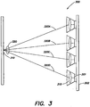
- FIG. 3 illustrates a schematic side view of the lighting fixture 300, showing four light sources 301 and their corresponding collimators 315.
- the light sources and collimators are arranged such the lighting fixture 300 produces a high-intensity narrow beam 320 of radiation impinging on a target illumination field 310, and that respective radiation beams 320A, 320B, 320C and 320D projected from each collimator/light source pair substantially overlap in the target illumination field to form the narrow beam 320.
- the phenomenon of chip or die imaging may be problematic.
- the geometric overall shape of the light emitting portion of the LED package itself e.g., the one or more chips
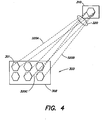
- FIG. 4 depicts an exaggerated illustration of this phenomenon.
- An exemplary lighting fixture 300 includes six hexagonally shaped light sources 301 mounted on a common mounting board 302; for purposes of the following discussion, it is assumed that the actual light emitting portion of each source is hexagonal in shape and coupled to corresponding collimators (not shown in FIG. 4 ), and that the light sources project respective beams of radiation (e.g., the beams 320A, 320B, and 320C) towards a target illumination field 310 (in practice, as discussed above, the light emitting portion of an LED package including one or more chips generally is square or rectangular).
- the beams projected from each light source/collimator pair at least partially overlap to form a narrow beam 320 of radiation that impinges upon the target illumination field 310. As shown in FIG.
- the far field irradiance distribution pattern of the narrow radiation beam 320 impinging upon the target illumination field 310 may have a general shape that resembles that of the light source chip(s); in this manner, the light emitting portion of an LED package may be "imaged" in the far field due to collimation, and may result in undesirable irradiation non-uniformity in some circumstances.
- multi-color packages such as RGGB, BGGA and RGBW
- spectral non-uniformities may result in the target illumination field 310, in which respective different source spectrums of the multi-color packages are concentrated in different areas of the target illumination field (rather than blended/mixed throughout the target illumination field).
- the orientation of the individual light sources relative to each other on the common mounting board 302 is selected such that their respective light projections, at least partially overlapping in the target illumination field, produce substantially uniform illumination in the target illumination field.
- a first reference axis is chosen for the common mounting board 302 of the lighting fixture.
- the common mounting board is rectangular in shape as shown in FIG. 2
- any line parallel to one side of the common mounting board may be selected as a first reference axis.
- a first reference axis 510 is selected as a "vertical" axis parallel to the vertical sides of the rectangular common mounting board 302; however, it should be appreciated that a horizontal axis parallel to one of the horizontal sides of the rectangular common mounting board alternatively may serve as a reference axis. More generally, virtually any line in the plane of the common mounting board 302 may serve as a reference axis for the mounting board.
- a second reference axis for each light source 301 is designated/selected.
- a second reference axis for each light source may be selected according to any of a variety of criteria, as long as the light source reference axis for each source is designated identically for all light sources to be employed in a given lighting fixture, such that when all light source reference axes are aligned in a same direction, all light sources have a same orientation relative to the first reference axis of the common mounting board.
- the chip area of each of the LED packages serving as light sources 301 has an essentially square or rectangular shape, and for purposes of illustration a light source axis is taken through the center of the chip area, parallel to the longer side of the rectangular shape.
- the light source 301A has a corresponding second reference axis 512A
- the light source 301B has a corresponding second reference axis 512B
- the light source 301C has a corresponding second reference axis 512C.
- any line parallel to the first reference axis 510 of the common mounting board 302 may serve as a reference for rotation of any light source in the fixture.
- the LED packages serving as the light sources 301 are disposed on the common mounting board 302 such that the orientations of at least two light sources relative to the first reference axis are different. More specifically, as shown in the example of FIG. 2 , the light source 301A is rotated such that its axis 512A forms an angle 514A with respect to a line 510A that is parallel to the first reference axis 510.
- the light source 301 Bis rotated such that its axis 512B forms an angle 514B with respect to a line 510B that is parallel to the first reference axis 510, and the light source 301C is rotated such that its axis 512C forms an angle 514C with respect to a line 510C that is parallel to the first reference axis 510.
- any one or more of the light sources 301 may be rotated in a clockwise or counter-clockwise manner, within a plane parallel to the plane of the common mounting board 302, and relative to a line parallel to the first reference axis 510, so that at least two of the light sources have different rotations/orientations (e.g., one light source may not be rotated, i.e., 0 degree rotation, while at least one other light source has a non-zero rotation, or at least two light sources may have respective different non-zero rotations, etc.).
- the rotation of a given light source may be measured with respect to the first reference axis 510, or rotations between different light sources may be measured. For example, in the diagram of FIG.
- the total rotation angle between the light sources 301A and 301B is determined by subtracting the angle 514B from the angle 514A
- the total rotation angle between the light sources 301B and 301C is determined by subtracting the angle 514C from the angle 514B.
- each LED package serving as a light source 301 has a unique orientation/rotation on the common mounting board 302 of the lighting fixture 300.
- any two LED packages can be disposed with a total rotation angle between their respective axes of nA, where n is an integer ranging from 1 to M-1, and A is an angle determined by dividing a maximum desired rotation span R max by M (and wherein the rotation angle of each source relative to the second reference axis 510 is measured in a same direction, i.e., either clockwise or counter-clockwise).
- the maximum desired rotation span R max is taken as 360 degrees; stated differently, the total of M packages of a given lighting fixture are rotated in even or approximately even increments determined by 360/M to cover a maximum rotation span of 360 degrees.
- the maximum desired rotation span R max is taken as 90 degrees (i.e., the M packages are rotated in even or approximately even increments determined by 90/M to cover a maximum rotation span of 90 degrees. More generally, the maximum desired rotation span R max may be chosen at least in part based on the rotational symmetry of the LED packages in question for a given fixture.
- a multi-color LED package including four different color chips forming an essentially square light emitting area.
- the rotational symmetry of such a package is 360 degrees; i.e., if the package is rotated in plane by 360 degrees, it looks the same (hence an appropriate R max for such a package is 360 degrees).
- a single-color LED package may in-dude four same color chips forming an essentially square light emitting area; in this example, the rotational symmetry is 90 degrees (i.e., if the package is rotated by 90 degrees, it looks the same), and hence an appropriate R max is 90 degrees.
- the uniquely-oriented LED packages can be disposed on the common mounting board in various patterns, as long as their projections at least partially overlap in the target illumination field 310, as shown in FIGS. 3 and 4 .
- FIG. 5 illustrates a projection lighting fixture 400 employing multi-color LED packages, according to one embodiment of the present invention.
- a simplified implementation involving only four multi-color light sources 401A, 401B, 401C and 401D is shown in FIG. 5 for purposes of illustrating the concepts discussed above in connection with the rotation of respective multi-color light sources. It should be appreciated that the concepts discussed below in connection with FIG. 5 may be extended to a projection lighting fixture according to the present invention including virtually any number of multi-color light sources.
- the four multi-color light sources 401A, 401B, 401C and 401D of the lighting fixture 400 are disposed on a common mounting board 402.
- a reference axis for the board 402 is indicated as the axis 510.
- the light sources are multi-color LED packages, wherein each LED package may comprise a COB LED assembly including at least four LED junctions configured to generate radiation of four different spectrums (e.g., RGBW).
- each LED package may include four die or chips, one for each different spectrum, such that the light generating portion of the COB LED assembly for each light source has a square shape.
- the far field irradiance distribution profile of a narrow-beam projected from the lighting fixture may have a "squarish" appearance due to the source (chip or die) imaging phenomenon.
- the target illumination field may suffer from spectral non-uniformity if same colors of each multi-color LED package are in a same orientation relative to one another.
- respective different source spectrums of the multi-color packages may be concentrated in different areas of the target illumination field (rather than blended/mixed throughout the target illumination field).
- each package is disposed at a 90-degree angle (360/4) relative to the adjacent package. More specifically, the package 401A has a reference axis 512A that is rotated by an angle 514A of 0 degrees with respect to the reference axis 510 for the common mounting board 402; similarly, the package 401B has a reference axis 512B that is rotated by an angle 514B of 90 degrees with respect to the reference axis 510, the package 401C has a reference axis 512C that is rotated by an angle 514C of 180 degrees with respect to the reference axis 510, and the package 401D has a reference axis 512D that is rotated by an angle 514D with respect to the reference axis 510.
- the sources 401A, 401B, 401C and 401D overlap, such that the different spectrums R (red), G (green), B (blue) and W (white) are projected into each quadrant in the illumination field and mix together, improving spectral uniformity in the target illumination field 410.
- the source imaging phenomenon may still result in a potentially squarish appearance to the beam pattern; however, spectral uniformity is significantly improved.
- the source imaging phenomenon may be significantly reduced in addition to the increased spectral uniformity.
- FIG. 6 illustrates a projection lighting fixture 600 according to another embodiment of the present invention employing same-color LED packages.
- the fixture 600 includes a housing 670 formed to receive an essentially circular common mounting board 602 on which multiple light sources 601 are disposed.
- the housing 670 includes a key 660 and the common mounting board 602 includes a notch 650 to determine an orientation of the board 602 in the fixture, and establish the reference axis 510 for the common mounting board 602.
- each of the light sources 601 includes a corresponding collimator 615, and may comprise a single-color LED package, such as the Cree® XLamp® XR-E LED package (available from Cree, Inc. of Durham, North Carolina) having an essentially square light emitting portion of the package. Due to the square geometry and single color, the rotational symmetry for such a package is 90 degrees. Hence, in the exemplary embodiment illustrated in FIG. 6 , R max may be taken as 90 degrees, and given nine light sources employed in the fixture, the angle A is 10 degrees, and any two LED packages are disposed with a total rotation angle between their respective axes of nA, where n is an integer ranging from 1 to 8.
- n is an integer ranging from 1 to 8.
Landscapes
- Physics & Mathematics (AREA)
- General Physics & Mathematics (AREA)
- Engineering & Computer Science (AREA)
- Optics & Photonics (AREA)
- General Engineering & Computer Science (AREA)
- Non-Portable Lighting Devices Or Systems Thereof (AREA)
- Led Device Packages (AREA)
- Fastening Of Light Sources Or Lamp Holders (AREA)
- Vessels And Coating Films For Discharge Lamps (AREA)
- Devices For Indicating Variable Information By Combining Individual Elements (AREA)
- Microelectronics & Electronic Packaging (AREA)
Claims (14)
- Beleuchtungsvorrichtung (300), umfassend: eine grundsätzlich planare Montageplatte (302), die eine erste Bezugsachse (510) in einer ersten, durch die Montageplatte definierten Ebene besitzt; und eine Vielzahl von LED-basierten Lichtquellen (301), die auf der Montageplatte angeordnet sind, wobei jede Lichtquelle eine zweite Bezugsachse (512A, 512B, 512C) besitzt, die eine Ausrichtung der Lichtquelle in der ersten Ebene angibt, wobei die zweite Bezugsachse jeder Lichtquelle für alle Lichtquellen aus der Vielzahl von Lichtquellen bezeichnet ist,
dadurch gekennzeichnet, dass
die Vielzahl von LED-basierten Lichtquellen derart auf der Montageplatte angeordnet sind, dass eine erste Ausrichtung (514A) einer ersten Lichtquelle (301A) aus der Vielzahl von Lichtquellen, wie durch ihre zweite Bezugsachse (512A) bezogen auf die erste Bezugsachse (510) der Montageplatte definiert, von mindestens einer anderen ersten Ausrichtung (514B) von mindestens einer anderen Lichtquelle (301B) aus der Vielzahl von Lichtquellen, wie durch ihre zweite Bezugsachse (512B) bezogen auf die erste Bezugsachse (510) der Montageplatte definiert, unterschiedlich ist, wobei die erste Lichtquelle dazu eingerichtet ist, einen ersten kollimierten Lichtstrahl zu projizieren, und die mindestens eine andere Lichtquelle dazu eingerichtet ist, mindestens einen anderen zweiten kollimierten Lichtstrahl zu projizieren, wobei der erste und zweite Strahl in unterschiedlichen Ausrichtungen kollimiert sind, die dem Ausrichtungsunterschied zwischen der ersten Ausrichtung und der mindestens einen anderen ersten Ausrichtung entsprechen, und derart eingerichtet sind, dass der erste und zweite kollimierte Strahl sich mindestens teilweise überlappen, um Abbildung des lichtemittierenden Abschnitts der LED-basierten Lichtquelle in einem Zielbeleuchtungsfeld zu reduzieren oder eliminieren. - Vorrichtung nach Anspruch 1, wobei jede LED-basierte Lichtquelle (301) ein LED-Paket einschließlich einer Chip-on-Board-Baugruppe aus mehreren LED-Chips umfasst.
- Vorrichtung nach Anspruch 2, wobei jede LED-basierte Lichtquelle weiter einen Kollimator (315) umfasst, der mit dem LED-Paket gekoppelt ist.
- Vorrichtung nach Anspruch 2, wobei mindestens die erste Ausrichtung (514A) der ersten Lichtquelle (301A) mindestens zum Teil auf mindestens einem Emissionsspektrum der mehreren LED-Chips basiert.
- Vorrichtung nach Anspruch 4, wobei mindestens die erste Ausrichtung der ersten Lichtquelle mindestens zum Teil auf einer Rotationssymmetrie des mindestens einen Emissionsspektrums der mehreren LED-Chips basiert.
- Vorrichtung nach Anspruch 2, wobei die mehreren LED-Chips in der Chip-on-Board-Baugruppe so eingerichtet sind, dass sie einen Lichtemissionsbereich bilden, der eine geometrische Form besitzt, und wobei mindestens die erste Ausrichtung der ersten Lichtquelle mindestens zum Teil auf einer Rotationssymmetrie der geometrischen Form basiert.
- Vorrichtung nach Anspruch 1, wobei jede Lichtquelle aus der Vielzahl von Lichtquellen bezogen auf die erste Bezugsachse der Montageplatte eine einmalige Ausrichtung besitzt.
- Verfahren von Bereitstellen von einheitlicher Projektionsbeleuchtung, wobei das Verfahren die Schritte umfasst des:Einrichtens einer Vielzahl von LED-basierten Lichtquellen (301) auf einer grundsätzlich planaren Montageplatte (302) derart, dass mindestens zwei LED-basierte Lichtquellen (301A, 301B) aus der Vielzahl von LED-basierten Lichtquellen bezogen auf eine erste Bezugsachse in einer von der gemeinsamen Montageplatte definierten Ebene unterschiedliche Ausrichtungen (514A, 514B) besitzen,wobei die Vielzahl von LED-basierten Lichtquellen, wenn sie erregt werden, eine entsprechende Vielzahl von kollimierten Lichtstrahlen zu einem Zielbeleuchtungsfeld hin projizieren, wobei sich die Strahlen im Zielbeleuchtungsfeld mindestens teilweise überlappen, wobei die Vielzahl von kollimierten Lichtstrahlen einen ersten kollimierten Lichtstrahl und einen zweiten kollimierten Lichtstrahl umfasst, wobei der erste und zweite Strahl in unterschiedlichen Ausrichtungen kollimiert sind, die dem Ausrichtungsunterschied zwischen den jeweiligen Ausrichtungen der jeweiligen LED-basierten Lichtquellen entsprechen, um im Wesentlichen einheitliche Beleuchtung im Zielbeleuchtungsfeld zu erzeugen und um Abbildung des lichtemittierenden Abschnitts der LED-basierten Lichtquelle im Zielbeleuchtungsfeld zu reduzieren oder eliminieren.
- Verfahren nach Anspruch 8, wobei die grundsätzlich planare Montageplatte (302) eine erste Bezugsachse (510) in einer ersten, durch die Montageplatte definierten Ebene besitzt; jede Lichtquelle eine zweite Bezugsachse (512A, 512B) besitzt, die eine Ausrichtung (514A, 514B) der Lichtquelle angibt, wobei die zweite Bezugsachse für jede Lichtquelle für alle Lichtquellen aus der Vielzahl von Lichtquellen identisch bezeichnet ist; und die Vielzahl von LED-basierten Lichtquellen derart auf der Montageplatte angeordnet sind, dass eine erste Ausrichtung (514A) einer ersten Lichtquelle (301A) aus der Vielzahl von Lichtquellen, wie durch ihre zweite Bezugsachse (512A) bezogen auf die erste Bezugsachse (510) der Montageplatte definiert, von mindestens einer anderen Ausrichtung (514B) von mindestens einer anderen Lichtquelle (301B) aus der Vielzahl von Lichtquellen, wie durch ihre zweite Bezugsachse (512B) bezogen auf die erste Bezugsachse (510) der Montageplatte definiert, unterschiedlich ist.
- Verfahren nach Anspruch 9, wobei jede LED-basierte Lichtquelle ein LED-Paket einschließlich einer Chip-on-Board-Baugruppe aus mehreren LED-Chips, und einen Kollimator umfasst, der mit dem LED-Paket gekoppelt ist.
- Verfahren nach Anspruch 9, wobei mindestens die erste Ausrichtung der ersten Lichtquelle mindestens zum Teil auf mindestens einem Emissionsspektrum der mehreren LED-Chips basiert.
- Verfahren nach Anspruch 11, wobei mindestens die erste Ausrichtung der ersten Lichtquelle mindestens zum Teil auf einer Symmetrie des mindestens einen Emissionsspektrums der mehreren LED-Chips basiert.
- Verfahren nach Anspruch 9, wobei die mehreren LED-Chips in der Chip-on-Board-Baugruppe so eingerichtet sind, dass sie einen Lichtemissionsbereich bilden, der eine geometrische Form besitzt, und wobei mindestens die erste Ausrichtung der ersten Lichtquelle mindestens zum Teil auf einer Rotationssymmetrie der geometrischen Form basiert.
- Verfahren nach Anspruch 9, wobei jede Lichtquelle aus der Vielzahl von Lichtquellen eine einmalige Ausrichtung zur ersten Bezugsachse der Montageplatte besitzt.
Priority Applications (1)
| Application Number | Priority Date | Filing Date | Title |
|---|---|---|---|
| PL07862228T PL2089656T5 (pl) | 2006-11-27 | 2007-11-27 | Sposób i urządzenie zapewniające równomierne oświetlenie projekcyjne |
Applications Claiming Priority (2)
| Application Number | Priority Date | Filing Date | Title |
|---|---|---|---|
| US86720606P | 2006-11-27 | 2006-11-27 | |
| PCT/US2007/024389 WO2008066785A2 (en) | 2006-11-27 | 2007-11-27 | Methods and apparatus for providing uniform projection lighting |
Publications (3)
| Publication Number | Publication Date |
|---|---|
| EP2089656A2 EP2089656A2 (de) | 2009-08-19 |
| EP2089656B1 EP2089656B1 (de) | 2011-03-02 |
| EP2089656B2 true EP2089656B2 (de) | 2018-05-23 |
Family
ID=39362344
Family Applications (1)
| Application Number | Title | Priority Date | Filing Date |
|---|---|---|---|
| EP07862228.9A Active EP2089656B2 (de) | 2006-11-27 | 2007-11-27 | Verfahren und Vorrichtung zum Bereitstellen einer gleichmässigen Projektionsbeleuchtung |
Country Status (13)
| Country | Link |
|---|---|
| US (1) | US7806558B2 (de) |
| EP (1) | EP2089656B2 (de) |
| JP (2) | JP5396278B2 (de) |
| KR (1) | KR101523993B1 (de) |
| CN (1) | CN101627253B (de) |
| AT (1) | ATE500469T2 (de) |
| BR (1) | BRPI0719124B1 (de) |
| DE (1) | DE602007012927D1 (de) |
| DK (1) | DK2089656T4 (de) |
| ES (1) | ES2362411T5 (de) |
| PL (1) | PL2089656T5 (de) |
| RU (1) | RU2446348C2 (de) |
| WO (1) | WO2008066785A2 (de) |
Families Citing this family (81)
| Publication number | Priority date | Publication date | Assignee | Title |
|---|---|---|---|---|
| US20050259424A1 (en) | 2004-05-18 | 2005-11-24 | Zampini Thomas L Ii | Collimating and controlling light produced by light emitting diodes |
| US7766511B2 (en) | 2006-04-24 | 2010-08-03 | Integrated Illumination Systems | LED light fixture |
| US7729941B2 (en) | 2006-11-17 | 2010-06-01 | Integrated Illumination Systems, Inc. | Apparatus and method of using lighting systems to enhance brand recognition |
| US8013538B2 (en) | 2007-01-26 | 2011-09-06 | Integrated Illumination Systems, Inc. | TRI-light |
| US7896521B2 (en) * | 2007-05-04 | 2011-03-01 | Abl Ip Holding Llc | Adjustable light distribution system |
| US8742686B2 (en) | 2007-09-24 | 2014-06-03 | Integrated Illumination Systems, Inc. | Systems and methods for providing an OEM level networked lighting system |
| US8255487B2 (en) | 2008-05-16 | 2012-08-28 | Integrated Illumination Systems, Inc. | Systems and methods for communicating in a lighting network |
| DE102008038778A1 (de) * | 2008-08-12 | 2010-02-25 | Bega Gantenbrink-Leuchten Kg | Farb-LED-Strahler |
| US8075165B2 (en) | 2008-10-14 | 2011-12-13 | Ledengin, Inc. | Total internal reflection lens and mechanical retention and locating device |
| CN201363590Y (zh) * | 2009-01-22 | 2009-12-16 | 上海开腾信号设备有限公司 | 光型饱满柔和的大功率led光源及使用该光源的大功率led照明灯 |
| US8439516B2 (en) * | 2009-04-12 | 2013-05-14 | Ip Consulting, Llc | Stereoscopic view light source, with multiple modes of operation |
| US8585245B2 (en) | 2009-04-23 | 2013-11-19 | Integrated Illumination Systems, Inc. | Systems and methods for sealing a lighting fixture |
| JP5370660B2 (ja) * | 2009-06-19 | 2013-12-18 | スタンレー電気株式会社 | 車両用灯具 |
| US8622569B1 (en) | 2009-07-17 | 2014-01-07 | Musco Corporation | Method, system and apparatus for controlling light distribution using swivel-mount led light sources |
| CH701854A1 (fr) * | 2009-09-17 | 2011-03-31 | Pasan Sa | Dispositif d'éclairage pour l'obtention d'un champ uniformément éclairé. |
| US20110089864A1 (en) * | 2009-10-19 | 2011-04-21 | Cory Wasniewski | Method and Apparatus for Controlling Power in a LED Lighting System |
| US8523403B2 (en) * | 2010-01-05 | 2013-09-03 | Altman Lighting Co., Inc. | LED white light luminaire with imaging capability |
| DE202010002125U1 (de) * | 2010-02-10 | 2011-08-30 | Zumtobel Lighting Gmbh | Anordnung zur Lichtabgabe mit punktförmigen Lichtquellen und Reflektor |
| DK177579B1 (en) * | 2010-04-23 | 2013-10-28 | Martin Professional As | Led light fixture with background lighting |
| US8888318B2 (en) * | 2010-06-11 | 2014-11-18 | Intematix Corporation | LED spotlight |
| US8147093B2 (en) * | 2010-06-14 | 2012-04-03 | Bridgelux | Light source having LEDs of selected spectral output, and method for constructing same |
| JP5611715B2 (ja) * | 2010-08-12 | 2014-10-22 | 日本応用光学株式会社 | 照明装置 |
| JP5611714B2 (ja) * | 2010-08-12 | 2014-10-22 | 日本応用光学株式会社 | 照明装置 |
| US9267663B2 (en) | 2010-08-12 | 2016-02-23 | Japan Applied Optics Co., Ltd. | Illumination device |
| US9066381B2 (en) | 2011-03-16 | 2015-06-23 | Integrated Illumination Systems, Inc. | System and method for low level dimming |
| CN102734645B (zh) * | 2011-04-01 | 2016-11-23 | 上海广茂达光艺科技股份有限公司 | Led投影灯具 |
| US20150237700A1 (en) | 2011-07-26 | 2015-08-20 | Hunter Industries, Inc. | Systems and methods to control color and brightness of lighting devices |
| US11917740B2 (en) | 2011-07-26 | 2024-02-27 | Hunter Industries, Inc. | Systems and methods for providing power and data to devices |
| US9609720B2 (en) | 2011-07-26 | 2017-03-28 | Hunter Industries, Inc. | Systems and methods for providing power and data to lighting devices |
| US9521725B2 (en) | 2011-07-26 | 2016-12-13 | Hunter Industries, Inc. | Systems and methods for providing power and data to lighting devices |
| US8710770B2 (en) | 2011-07-26 | 2014-04-29 | Hunter Industries, Inc. | Systems and methods for providing power and data to lighting devices |
| US10874003B2 (en) | 2011-07-26 | 2020-12-22 | Hunter Industries, Inc. | Systems and methods for providing power and data to devices |
| CN103975190A (zh) * | 2011-09-26 | 2014-08-06 | 马斯科公司 | 具有多光源准直器的照明系统及其操作方法 |
| DE102011083891A1 (de) * | 2011-09-30 | 2013-04-04 | Osram Gmbh | Gobo-Projektor |
| JP5499071B2 (ja) * | 2012-04-17 | 2014-05-21 | シャープ株式会社 | 中継コネクタ及びこれを備える光源モジュール |
| US8894437B2 (en) | 2012-07-19 | 2014-11-25 | Integrated Illumination Systems, Inc. | Systems and methods for connector enabling vertical removal |
| JP2014093129A (ja) * | 2012-10-31 | 2014-05-19 | Toshiba Lighting & Technology Corp | 発光ユニット及び照明器具 |
| US9379578B2 (en) | 2012-11-19 | 2016-06-28 | Integrated Illumination Systems, Inc. | Systems and methods for multi-state power management |
| US20140168963A1 (en) * | 2012-12-18 | 2014-06-19 | Musco Corporation | Multi-led lens with light pattern optimization |
| US9420665B2 (en) | 2012-12-28 | 2016-08-16 | Integration Illumination Systems, Inc. | Systems and methods for continuous adjustment of reference signal to control chip |
| US9485814B2 (en) | 2013-01-04 | 2016-11-01 | Integrated Illumination Systems, Inc. | Systems and methods for a hysteresis based driver using a LED as a voltage reference |
| CN103196066B (zh) * | 2013-04-19 | 2014-10-22 | 深圳市实益达科技股份有限公司 | 窄光束led照明光学系统及其设计方法 |
| WO2015009739A1 (en) * | 2013-07-18 | 2015-01-22 | Kla-Tencor Corporation | Illumination configurations for scatterometry measurements |
| EP3090203A1 (de) | 2013-11-20 | 2016-11-09 | Philips Lighting Holding B.V. | Verfahren und vorrichtung zum gleichmässigen beleuchtung einer oberfläche |
| US9726362B2 (en) * | 2014-01-08 | 2017-08-08 | Vitec Videocom Inc. | LED heater system and method |
| WO2016001271A1 (en) | 2014-07-01 | 2016-01-07 | Koninklijke Philips N.V. | A lighting device providing light mixed from several light sources |
| US10085328B2 (en) | 2014-08-11 | 2018-09-25 | RAB Lighting Inc. | Wireless lighting control systems and methods |
| US9883567B2 (en) | 2014-08-11 | 2018-01-30 | RAB Lighting Inc. | Device indication and commissioning for a lighting control system |
| US10531545B2 (en) | 2014-08-11 | 2020-01-07 | RAB Lighting Inc. | Commissioning a configurable user control device for a lighting control system |
| US10039174B2 (en) | 2014-08-11 | 2018-07-31 | RAB Lighting Inc. | Systems and methods for acknowledging broadcast messages in a wireless lighting control network |
| KR101692290B1 (ko) * | 2015-03-31 | 2017-01-04 | (주) 디엠라이트 | 색온도 조절이 가능한 엘이디 조명장치 |
| CA2986450A1 (en) * | 2015-05-18 | 2016-11-24 | Terabee S.A.S. | Device and method for uniform far-field illumination with leds |
| US10228711B2 (en) | 2015-05-26 | 2019-03-12 | Hunter Industries, Inc. | Decoder systems and methods for irrigation control |
| US10918030B2 (en) | 2015-05-26 | 2021-02-16 | Hunter Industries, Inc. | Decoder systems and methods for irrigation control |
| US10060599B2 (en) | 2015-05-29 | 2018-08-28 | Integrated Illumination Systems, Inc. | Systems, methods and apparatus for programmable light fixtures |
| US10030844B2 (en) | 2015-05-29 | 2018-07-24 | Integrated Illumination Systems, Inc. | Systems, methods and apparatus for illumination using asymmetrical optics |
| KR20170025287A (ko) * | 2015-08-28 | 2017-03-08 | 주식회사 쏠컴포넌트 | 색혼합 및 청색광 차단 기능을 갖는 발광 다이오드 모듈 및 이를 포함한 조명 장치 |
| US10323826B2 (en) | 2015-10-20 | 2019-06-18 | Signify Holding B.V. | Optical system, method, and applications |
| JP6865570B2 (ja) * | 2016-12-07 | 2021-04-28 | シチズン電子株式会社 | 発光装置 |
| US10400994B2 (en) * | 2016-12-19 | 2019-09-03 | Whelen Engineering Company, Inc. | LED illumination module with fixed optic and variable emission pattern |
| US10420177B2 (en) * | 2016-12-19 | 2019-09-17 | Whelen Engineering Company, Inc. | LED illumination module with fixed optic and variable emission pattern |
| JP6901116B2 (ja) * | 2017-02-15 | 2021-07-14 | かがつう株式会社 | 照明器具 |
| RU2650102C1 (ru) * | 2017-04-04 | 2018-04-09 | федеральное государственное бюджетное образовательное учреждение высшего образования "Ульяновский государственный технический университет" | Осветительное устройство |
| US10571788B2 (en) * | 2017-07-25 | 2020-02-25 | Seiko Epson Corporation | Light source device, illumination device, and projector |
| EP3682159B1 (de) * | 2017-09-14 | 2020-12-23 | Signify Holding B.V. | Beleuchtungsvorrichtung und verfahren zur herstellung einer beleuchtungsvorrichtung |
| JP7068686B2 (ja) * | 2017-12-08 | 2022-05-17 | 丸茂電機株式会社 | 調色led照明装置 |
| JP2019186054A (ja) * | 2018-04-11 | 2019-10-24 | ウシオライティング株式会社 | 空間照明用の光源装置 |
| DE102018215951A1 (de) * | 2018-09-19 | 2020-03-19 | Osram Gmbh | Lichtemittierende vorrichtung und verfahren zum herstellen derselben |
| US10883673B2 (en) | 2019-02-14 | 2021-01-05 | Simply Leds, Llc | Dithered LEDs to reduce color banding in lensed light fixtures |
| US10801714B1 (en) | 2019-10-03 | 2020-10-13 | CarJamz, Inc. | Lighting device |
| CN112289201A (zh) * | 2020-09-18 | 2021-01-29 | 惠州徳为智能技术有限公司 | 一种led显示屏布局方法 |
| CN213781461U (zh) * | 2020-09-30 | 2021-07-23 | 惠州徳为智能技术有限公司 | 一种led球型显示屏 |
| JP7576751B2 (ja) * | 2021-03-30 | 2024-11-01 | パナソニックIpマネジメント株式会社 | 照明装置 |
| DE202021102154U1 (de) * | 2021-04-22 | 2022-07-25 | Ledlenser GmbH & Co. KG | Leuchte |
| CA3192134A1 (en) * | 2022-03-07 | 2023-09-07 | Lmpg Inc. | Led lighting fixture having multiple led clusters with relative angular displacement (rotation) |
| JP2023182040A (ja) * | 2022-06-14 | 2023-12-26 | シチズン電子株式会社 | 発光モジュール |
| US12416908B2 (en) | 2022-12-29 | 2025-09-16 | Integrated Illumination Systems, Inc. | Systems and methods for manufacturing light fixtures |
| US12297996B2 (en) | 2023-02-16 | 2025-05-13 | Integrated Illumination Systems, Inc. | Cove light fixture with hidden integrated air return |
| CN219082949U (zh) * | 2023-02-16 | 2023-05-26 | 深圳市影友摄影器材有限公司 | 摄像平板灯 |
| CN221352789U (zh) * | 2023-11-16 | 2024-07-16 | 李文杰 | 一种led发光结构及其头灯 |
| US12342671B1 (en) * | 2024-11-06 | 2025-06-24 | Lmpg Inc. | TIR cluster for color mixing |
Family Cites Families (17)
| Publication number | Priority date | Publication date | Assignee | Title |
|---|---|---|---|---|
| AUPO163696A0 (en) * | 1996-08-13 | 1996-09-05 | Eveready Battery Company Inc. | Lighting devices, methods of constructing lighting devices and methods of operating lighting devices |
| JP3195294B2 (ja) * | 1998-08-27 | 2001-08-06 | スタンレー電気株式会社 | 車両用灯具 |
| US6200002B1 (en) * | 1999-03-26 | 2001-03-13 | Philips Electronics North America Corp. | Luminaire having a reflector for mixing light from a multi-color array of leds |
| US6367949B1 (en) * | 1999-08-04 | 2002-04-09 | 911 Emergency Products, Inc. | Par 36 LED utility lamp |
| TW457732B (en) * | 1999-08-27 | 2001-10-01 | Lumileds Lighting Bv | Luminaire, optical element and method of illuminating an object |
| DE10016381A1 (de) * | 2000-03-29 | 2001-10-04 | Franc Godler | Overhead-Projektor mit Flächenlichtquelle |
| US6585395B2 (en) * | 2001-03-22 | 2003-07-01 | Altman Stage Lighting Co., Inc. | Variable beam light emitting diode light source system |
| JP2002374004A (ja) * | 2001-06-14 | 2002-12-26 | Nitto Kogaku Kk | Ledアレイパネルおよび照明装置 |
| JP2003078175A (ja) * | 2001-09-05 | 2003-03-14 | Asahi Matsushita Electric Works Ltd | 疑似白色発光装置 |
| US6749310B2 (en) * | 2001-09-07 | 2004-06-15 | Contrast Lighting Services, Inc. | Wide area lighting effects system |
| RU2248025C2 (ru) * | 2002-07-09 | 2005-03-10 | Марков Валерий Николаевич | Светодиодный проектор и способ предоставления информации на экране |
| JP3809136B2 (ja) * | 2002-08-21 | 2006-08-16 | ペンタックス株式会社 | 測点指示装置 |
| US20040184270A1 (en) * | 2003-03-17 | 2004-09-23 | Halter Michael A. | LED light module with micro-reflector cavities |
| JP4281407B2 (ja) * | 2003-05-14 | 2009-06-17 | セイコーエプソン株式会社 | 照明装置および投射型表示装置 |
| JP2004349130A (ja) * | 2003-05-22 | 2004-12-09 | Koito Mfg Co Ltd | 車両用灯具 |
| JP4339028B2 (ja) * | 2003-06-19 | 2009-10-07 | 株式会社小糸製作所 | 灯具ユニットおよび車両用前照灯 |
| DE102005022832A1 (de) * | 2005-05-11 | 2006-11-16 | Arnold & Richter Cine Technik Gmbh & Co. Betriebs Kg | Scheinwerfer für Film- und Videoaufnahmen |
-
2007
- 2007-11-27 EP EP07862228.9A patent/EP2089656B2/de active Active
- 2007-11-27 CN CN2007800439337A patent/CN101627253B/zh active Active
- 2007-11-27 DE DE602007012927T patent/DE602007012927D1/de active Active
- 2007-11-27 US US11/945,480 patent/US7806558B2/en active Active
- 2007-11-27 BR BRPI0719124-3A patent/BRPI0719124B1/pt active IP Right Grant
- 2007-11-27 AT AT07862228T patent/ATE500469T2/de active
- 2007-11-27 WO PCT/US2007/024389 patent/WO2008066785A2/en not_active Ceased
- 2007-11-27 PL PL07862228T patent/PL2089656T5/pl unknown
- 2007-11-27 KR KR1020097013310A patent/KR101523993B1/ko active Active
- 2007-11-27 RU RU2009124435/28A patent/RU2446348C2/ru active
- 2007-11-27 DK DK07862228.9T patent/DK2089656T4/en active
- 2007-11-27 JP JP2009538417A patent/JP5396278B2/ja active Active
- 2007-11-27 ES ES07862228.9T patent/ES2362411T5/es active Active
-
2013
- 2013-10-21 JP JP2013218657A patent/JP5974242B2/ja active Active
Also Published As
| Publication number | Publication date |
|---|---|
| JP5396278B2 (ja) | 2014-01-22 |
| DK2089656T4 (en) | 2018-07-02 |
| CN101627253B (zh) | 2011-05-18 |
| DE602007012927D1 (de) | 2011-04-14 |
| JP2010511269A (ja) | 2010-04-08 |
| ES2362411T5 (es) | 2018-07-06 |
| CN101627253A (zh) | 2010-01-13 |
| EP2089656A2 (de) | 2009-08-19 |
| RU2009124435A (ru) | 2011-01-10 |
| PL2089656T5 (pl) | 2018-11-30 |
| ES2362411T3 (es) | 2011-07-05 |
| JP5974242B2 (ja) | 2016-08-23 |
| US20080123057A1 (en) | 2008-05-29 |
| JP2014067716A (ja) | 2014-04-17 |
| EP2089656B1 (de) | 2011-03-02 |
| KR101523993B1 (ko) | 2015-05-29 |
| WO2008066785A3 (en) | 2008-08-14 |
| BRPI0719124B1 (pt) | 2019-02-12 |
| PL2089656T3 (pl) | 2011-11-30 |
| WO2008066785A9 (en) | 2009-01-22 |
| DK2089656T3 (da) | 2011-06-20 |
| BRPI0719124A2 (pt) | 2013-12-17 |
| ATE500469T2 (de) | 2011-03-15 |
| KR20090094007A (ko) | 2009-09-02 |
| WO2008066785A2 (en) | 2008-06-05 |
| RU2446348C2 (ru) | 2012-03-27 |
| US7806558B2 (en) | 2010-10-05 |
Similar Documents
| Publication | Publication Date | Title |
|---|---|---|
| EP2089656B2 (de) | Verfahren und Vorrichtung zum Bereitstellen einer gleichmässigen Projektionsbeleuchtung | |
| RU2624453C2 (ru) | Светильник с расщепленным пучком и осветительная система | |
| TWI588409B (zh) | 用於照明裝置之混合反射系統 | |
| EP2655957B1 (de) | Led-glühlampe mit lichtstreuungsoptik | |
| US9109779B2 (en) | Defocused optic for multi-chip LED | |
| EP2724187B1 (de) | Led-basierte beleuchtungseinheit mit einer optischen komponente zum mischen von licht aus mehreren leds | |
| JP5696980B2 (ja) | 照明器具 | |
| WO2013041993A2 (en) | Led-based luminaire having a mixing optic | |
| US10302278B2 (en) | LED bulb with back-reflecting optic | |
| JP6460581B2 (ja) | 照明器具 | |
| US11719398B1 (en) | Recessed downlight | |
| JP6256528B2 (ja) | 照明器具 | |
| JP5950138B2 (ja) | 照明器具 | |
| JP6061215B2 (ja) | 照明器具 | |
| JP2023018868A (ja) | 照明器具 |
Legal Events
| Date | Code | Title | Description |
|---|---|---|---|
| PUAI | Public reference made under article 153(3) epc to a published international application that has entered the european phase |
Free format text: ORIGINAL CODE: 0009012 |
|
| 17P | Request for examination filed |
Effective date: 20090629 |
|
| AK | Designated contracting states |
Kind code of ref document: A2 Designated state(s): AT BE BG CH CY CZ DE DK EE ES FI FR GB GR HU IE IS IT LI LT LU LV MC MT NL PL PT RO SE SI SK TR |
|
| DAX | Request for extension of the european patent (deleted) | ||
| GRAP | Despatch of communication of intention to grant a patent |
Free format text: ORIGINAL CODE: EPIDOSNIGR1 |
|
| GRAS | Grant fee paid |
Free format text: ORIGINAL CODE: EPIDOSNIGR3 |
|
| GRAA | (expected) grant |
Free format text: ORIGINAL CODE: 0009210 |
|
| AK | Designated contracting states |
Kind code of ref document: B1 Designated state(s): AT BE BG CH CY CZ DE DK EE ES FI FR GB GR HU IE IS IT LI LT LU LV MC MT NL PL PT RO SE SI SK TR |
|
| REG | Reference to a national code |
Ref country code: GB Ref legal event code: FG4D |
|
| REG | Reference to a national code |
Ref country code: CH Ref legal event code: EP |
|
| REG | Reference to a national code |
Ref country code: IE Ref legal event code: FG4D |
|
| REF | Corresponds to: |
Ref document number: 602007012927 Country of ref document: DE Date of ref document: 20110414 Kind code of ref document: P |
|
| REG | Reference to a national code |
Ref country code: DE Ref legal event code: R096 Ref document number: 602007012927 Country of ref document: DE Effective date: 20110414 |
|
| REG | Reference to a national code |
Ref country code: DK Ref legal event code: T3 |
|
| REG | Reference to a national code |
Ref country code: SE Ref legal event code: TRGR |
|
| REG | Reference to a national code |
Ref country code: NL Ref legal event code: T3 |
|
| REG | Reference to a national code |
Ref country code: ES Ref legal event code: FG2A Ref document number: 2362411 Country of ref document: ES Kind code of ref document: T3 Effective date: 20110705 |
|
| PG25 | Lapsed in a contracting state [announced via postgrant information from national office to epo] |
Ref country code: LT Free format text: LAPSE BECAUSE OF FAILURE TO SUBMIT A TRANSLATION OF THE DESCRIPTION OR TO PAY THE FEE WITHIN THE PRESCRIBED TIME-LIMIT Effective date: 20110302 Ref country code: LV Free format text: LAPSE BECAUSE OF FAILURE TO SUBMIT A TRANSLATION OF THE DESCRIPTION OR TO PAY THE FEE WITHIN THE PRESCRIBED TIME-LIMIT Effective date: 20110302 Ref country code: GR Free format text: LAPSE BECAUSE OF FAILURE TO SUBMIT A TRANSLATION OF THE DESCRIPTION OR TO PAY THE FEE WITHIN THE PRESCRIBED TIME-LIMIT Effective date: 20110603 |
|
| LTIE | Lt: invalidation of european patent or patent extension |
Effective date: 20110302 |
|
| PG25 | Lapsed in a contracting state [announced via postgrant information from national office to epo] |
Ref country code: SI Free format text: LAPSE BECAUSE OF FAILURE TO SUBMIT A TRANSLATION OF THE DESCRIPTION OR TO PAY THE FEE WITHIN THE PRESCRIBED TIME-LIMIT Effective date: 20110302 Ref country code: CY Free format text: LAPSE BECAUSE OF FAILURE TO SUBMIT A TRANSLATION OF THE DESCRIPTION OR TO PAY THE FEE WITHIN THE PRESCRIBED TIME-LIMIT Effective date: 20110302 Ref country code: BG Free format text: LAPSE BECAUSE OF FAILURE TO SUBMIT A TRANSLATION OF THE DESCRIPTION OR TO PAY THE FEE WITHIN THE PRESCRIBED TIME-LIMIT Effective date: 20110602 Ref country code: FI Free format text: LAPSE BECAUSE OF FAILURE TO SUBMIT A TRANSLATION OF THE DESCRIPTION OR TO PAY THE FEE WITHIN THE PRESCRIBED TIME-LIMIT Effective date: 20110302 |
|
| PG25 | Lapsed in a contracting state [announced via postgrant information from national office to epo] |
Ref country code: EE Free format text: LAPSE BECAUSE OF FAILURE TO SUBMIT A TRANSLATION OF THE DESCRIPTION OR TO PAY THE FEE WITHIN THE PRESCRIBED TIME-LIMIT Effective date: 20110302 Ref country code: PT Free format text: LAPSE BECAUSE OF FAILURE TO SUBMIT A TRANSLATION OF THE DESCRIPTION OR TO PAY THE FEE WITHIN THE PRESCRIBED TIME-LIMIT Effective date: 20110704 |
|
| PG25 | Lapsed in a contracting state [announced via postgrant information from national office to epo] |
Ref country code: IS Free format text: LAPSE BECAUSE OF FAILURE TO SUBMIT A TRANSLATION OF THE DESCRIPTION OR TO PAY THE FEE WITHIN THE PRESCRIBED TIME-LIMIT Effective date: 20110702 Ref country code: RO Free format text: LAPSE BECAUSE OF FAILURE TO SUBMIT A TRANSLATION OF THE DESCRIPTION OR TO PAY THE FEE WITHIN THE PRESCRIBED TIME-LIMIT Effective date: 20110302 Ref country code: SK Free format text: LAPSE BECAUSE OF FAILURE TO SUBMIT A TRANSLATION OF THE DESCRIPTION OR TO PAY THE FEE WITHIN THE PRESCRIBED TIME-LIMIT Effective date: 20110302 |
|
| REG | Reference to a national code |
Ref country code: PL Ref legal event code: T3 |
|
| PLBI | Opposition filed |
Free format text: ORIGINAL CODE: 0009260 |
|
| PLAX | Notice of opposition and request to file observation + time limit sent |
Free format text: ORIGINAL CODE: EPIDOSNOBS2 |
|
| 26 | Opposition filed |
Opponent name: L'ECLAIRAGE TECHNIQUE-ECLATEC SAS Effective date: 20111202 |
|
| REG | Reference to a national code |
Ref country code: DE Ref legal event code: R026 Ref document number: 602007012927 Country of ref document: DE Effective date: 20111202 |
|
| PLAF | Information modified related to communication of a notice of opposition and request to file observations + time limit |
Free format text: ORIGINAL CODE: EPIDOSCOBS2 |
|
| PLBP | Opposition withdrawn |
Free format text: ORIGINAL CODE: 0009264 |
|
| PG25 | Lapsed in a contracting state [announced via postgrant information from national office to epo] |
Ref country code: MC Free format text: LAPSE BECAUSE OF NON-PAYMENT OF DUE FEES Effective date: 20111130 |
|
| PLBB | Reply of patent proprietor to notice(s) of opposition received |
Free format text: ORIGINAL CODE: EPIDOSNOBS3 |
|
| REG | Reference to a national code |
Ref country code: IE Ref legal event code: MM4A |
|
| PG25 | Lapsed in a contracting state [announced via postgrant information from national office to epo] |
Ref country code: IE Free format text: LAPSE BECAUSE OF NON-PAYMENT OF DUE FEES Effective date: 20111127 |
|
| PLAB | Opposition data, opponent's data or that of the opponent's representative modified |
Free format text: ORIGINAL CODE: 0009299OPPO |
|
| PG25 | Lapsed in a contracting state [announced via postgrant information from national office to epo] |
Ref country code: MT Free format text: LAPSE BECAUSE OF FAILURE TO SUBMIT A TRANSLATION OF THE DESCRIPTION OR TO PAY THE FEE WITHIN THE PRESCRIBED TIME-LIMIT Effective date: 20110302 |
|
| PG25 | Lapsed in a contracting state [announced via postgrant information from national office to epo] |
Ref country code: LU Free format text: LAPSE BECAUSE OF NON-PAYMENT OF DUE FEES Effective date: 20111127 |
|
| PG25 | Lapsed in a contracting state [announced via postgrant information from national office to epo] |
Ref country code: TR Free format text: LAPSE BECAUSE OF FAILURE TO SUBMIT A TRANSLATION OF THE DESCRIPTION OR TO PAY THE FEE WITHIN THE PRESCRIBED TIME-LIMIT Effective date: 20110302 |
|
| PG25 | Lapsed in a contracting state [announced via postgrant information from national office to epo] |
Ref country code: HU Free format text: LAPSE BECAUSE OF FAILURE TO SUBMIT A TRANSLATION OF THE DESCRIPTION OR TO PAY THE FEE WITHIN THE PRESCRIBED TIME-LIMIT Effective date: 20110302 |
|
| RIC2 | Information provided on ipc code assigned after grant |
Ipc: G03B 21/20 20060101ALI20131118BHEP Ipc: F21Y 101/02 20060101ALN20131118BHEP Ipc: F21Y 105/00 20060101ALN20131118BHEP Ipc: F21V 7/00 20060101AFI20131118BHEP Ipc: F21K 99/00 20100101ALI20131118BHEP Ipc: F21Y 113/00 20060101ALN20131118BHEP |
|
| APBM | Appeal reference recorded |
Free format text: ORIGINAL CODE: EPIDOSNREFNO |
|
| APBP | Date of receipt of notice of appeal recorded |
Free format text: ORIGINAL CODE: EPIDOSNNOA2O |
|
| APAH | Appeal reference modified |
Free format text: ORIGINAL CODE: EPIDOSCREFNO |
|
| APBQ | Date of receipt of statement of grounds of appeal recorded |
Free format text: ORIGINAL CODE: EPIDOSNNOA3O |
|
| RAP2 | Party data changed (patent owner data changed or rights of a patent transferred) |
Owner name: PHILIPS LIGHTING NORTH AMERICA CORPORATION |
|
| REG | Reference to a national code |
Ref country code: FR Ref legal event code: PLFP Year of fee payment: 9 |
|
| REG | Reference to a national code |
Ref country code: DE Ref legal event code: R081 Ref document number: 602007012927 Country of ref document: DE Owner name: SIGNIFY NORTH AMERICA CORPORATION, SOMERSET, US Free format text: FORMER OWNER: PHILIPS SOLID-STATE LIGHTING SOLUTIONS INC., BURLINGTON, MASS., US Ref country code: DE Ref legal event code: R082 Ref document number: 602007012927 Country of ref document: DE Representative=s name: VOLMER, GEORG, DIPL.-ING., DE Ref country code: DE Ref legal event code: R081 Ref document number: 602007012927 Country of ref document: DE Owner name: PHILIPS LIGHTING NORTH AMERICA CORP. (N.D.GES., US Free format text: FORMER OWNER: PHILIPS SOLID-STATE LIGHTING SOLUTIONS INC., BURLINGTON, MASS., US Ref country code: DE Ref legal event code: R082 Ref document number: 602007012927 Country of ref document: DE Representative=s name: MEISSNER BOLTE PATENTANWAELTE RECHTSANWAELTE P, DE |
|
| REG | Reference to a national code |
Ref country code: NL Ref legal event code: HC Owner name: PHILIPS LIGHTING NORTH AMERICA CORPORATION; US Free format text: DETAILS ASSIGNMENT: VERANDERING VAN EIGENAAR(S), VERANDERING VAN NAAM VAN DE EIGENAAR(S); FORMER OWNER NAME: PHILIPS SOLID-STATE LIGHTING SOLUTIONS, INC. Effective date: 20151201 |
|
| REG | Reference to a national code |
Ref country code: CH Ref legal event code: PFA Owner name: PHILIPS LIGHTING NORTH AMERICA CORPORATION, US Free format text: FORMER OWNER: PHILIPS SOLID-STATE LIGHTING SOLUTIONS, INC., US |
|
| REG | Reference to a national code |
Ref country code: FR Ref legal event code: PLFP Year of fee payment: 10 |
|
| REG | Reference to a national code |
Ref country code: DE Ref legal event code: R082 Ref document number: 602007012927 Country of ref document: DE Representative=s name: MEISSNER BOLTE PATENTANWAELTE RECHTSANWAELTE P, DE |
|
| REG | Reference to a national code |
Ref country code: AT Ref legal event code: HC Ref document number: 500469 Country of ref document: AT Kind code of ref document: T Owner name: PHILIPS LIGHTING NORTH AMERICA CORPORATION, US Effective date: 20170630 |
|
| APBU | Appeal procedure closed |
Free format text: ORIGINAL CODE: EPIDOSNNOA9O |
|
| REG | Reference to a national code |
Ref country code: FR Ref legal event code: PLFP Year of fee payment: 11 |
|
| PUAH | Patent maintained in amended form |
Free format text: ORIGINAL CODE: 0009272 |
|
| STAA | Information on the status of an ep patent application or granted ep patent |
Free format text: STATUS: PATENT MAINTAINED AS AMENDED |
|
| 27A | Patent maintained in amended form |
Effective date: 20180523 |
|
| AK | Designated contracting states |
Kind code of ref document: B2 Designated state(s): AT BE BG CH CY CZ DE DK EE ES FI FR GB GR HU IE IS IT LI LT LU LV MC MT NL PL PT RO SE SI SK TR |
|
| REG | Reference to a national code |
Ref country code: DE Ref legal event code: R102 Ref document number: 602007012927 Country of ref document: DE |
|
| REG | Reference to a national code |
Ref country code: CH Ref legal event code: AELC |
|
| REG | Reference to a national code |
Ref country code: DK Ref legal event code: T4 Effective date: 20180628 |
|
| REG | Reference to a national code |
Ref country code: ES Ref legal event code: DC2A Ref document number: 2362411 Country of ref document: ES Kind code of ref document: T5 Effective date: 20180706 |
|
| REG | Reference to a national code |
Ref country code: BE Ref legal event code: HC Owner name: PHILIPS LIGHTING NORTH AMERICA CORPORATION; US Free format text: DETAILS ASSIGNMENT: CHANGE OF OWNER(S), CHANGEMENT NOM PROPRIETAIRE, NOM /ADRESSE; FORMER OWNER NAME: PHILIPS SOLID-STATE LIGHTING SOLUTIONS, INC. Effective date: 20170310 |
|
| REG | Reference to a national code |
Ref country code: NL Ref legal event code: FP |
|
| REG | Reference to a national code |
Ref country code: SE Ref legal event code: RPEO |
|
| REG | Reference to a national code |
Ref country code: CH Ref legal event code: PK Free format text: BERICHTIGUNGEN |
|
| RIC2 | Information provided on ipc code assigned after grant |
Ipc: F21K 99/00 20160101ALI20131118BHEP Ipc: F21Y 113/00 20160101ALN20131118BHEP Ipc: G03B 21/20 20060101ALI20131118BHEP Ipc: F21V 7/00 20060101AFI20131118BHEP Ipc: F21Y 101/02 20000101ALN20131118BHEP Ipc: F21Y 105/00 20160101ALN20131118BHEP |
|
| REG | Reference to a national code |
Ref country code: NL Ref legal event code: HC Owner name: SIGNIFY NORTH AMERICA CORPORATION; US Free format text: DETAILS ASSIGNMENT: CHANGE OF OWNER(S), CHANGE OF OWNER(S) NAME; FORMER OWNER NAME: PHILIPS SOLID-STATE LIGHTING SOLUTIONS, INC. Effective date: 20200304 |
|
| REG | Reference to a national code |
Ref country code: BE Ref legal event code: HC Owner name: SIGNIFY NORTH AMERICA CORPORATION; US Free format text: DETAILS ASSIGNMENT: CHANGE OF OWNER(S), CHANGEMENT DE NOM DU PROPRIETAIRE; FORMER OWNER NAME: PHILIPS LIGHTING NORTH AMERICA CORPORATION Effective date: 20200214 |
|
| REG | Reference to a national code |
Ref country code: ES Ref legal event code: PC2A Owner name: SIGNIFY NORTH AMERICA CORPORATION Effective date: 20201015 |
|
| REG | Reference to a national code |
Ref country code: DE Ref legal event code: R082 Ref document number: 602007012927 Country of ref document: DE Representative=s name: MEISSNER BOLTE PATENTANWAELTE RECHTSANWAELTE P, DE Ref country code: DE Ref legal event code: R081 Ref document number: 602007012927 Country of ref document: DE Owner name: SIGNIFY NORTH AMERICA CORPORATION, SOMERSET, US Free format text: FORMER OWNER: PHILIPS LIGHTING NORTH AMERICA CORP. (N.D.GES.D. STAATES DELAWARE), SOMERSET, N.J., US |
|
| REG | Reference to a national code |
Ref country code: AT Ref legal event code: HC Ref document number: 500469 Country of ref document: AT Kind code of ref document: T Owner name: SIGNIFY NORTH AMERICA CORPORATION, US Effective date: 20210315 |
|
| REG | Reference to a national code |
Ref country code: AT Ref legal event code: UEP Ref document number: 500469 Country of ref document: AT Kind code of ref document: T Effective date: 20180523 |
|
| P01 | Opt-out of the competence of the unified patent court (upc) registered |
Effective date: 20230421 |
|
| REG | Reference to a national code |
Ref country code: CH Ref legal event code: U11 Free format text: ST27 STATUS EVENT CODE: U-0-0-U10-U11 (AS PROVIDED BY THE NATIONAL OFFICE) Effective date: 20251201 |
|
| PGFP | Annual fee paid to national office [announced via postgrant information from national office to epo] |
Ref country code: NL Payment date: 20251124 Year of fee payment: 19 |
|
| PGFP | Annual fee paid to national office [announced via postgrant information from national office to epo] |
Ref country code: GB Payment date: 20251125 Year of fee payment: 19 |
|
| PGFP | Annual fee paid to national office [announced via postgrant information from national office to epo] |
Ref country code: AT Payment date: 20251118 Year of fee payment: 19 |
|
| PGFP | Annual fee paid to national office [announced via postgrant information from national office to epo] |
Ref country code: IT Payment date: 20251121 Year of fee payment: 19 Ref country code: DK Payment date: 20251124 Year of fee payment: 19 |
|
| PGFP | Annual fee paid to national office [announced via postgrant information from national office to epo] |
Ref country code: FR Payment date: 20251124 Year of fee payment: 19 |
|
| PGFP | Annual fee paid to national office [announced via postgrant information from national office to epo] |
Ref country code: BE Payment date: 20251124 Year of fee payment: 19 |
|
| PGFP | Annual fee paid to national office [announced via postgrant information from national office to epo] |
Ref country code: SE Payment date: 20251124 Year of fee payment: 19 Ref country code: CH Payment date: 20251201 Year of fee payment: 19 |
|
| PGFP | Annual fee paid to national office [announced via postgrant information from national office to epo] |
Ref country code: CZ Payment date: 20251120 Year of fee payment: 19 |
|
| PGFP | Annual fee paid to national office [announced via postgrant information from national office to epo] |
Ref country code: PL Payment date: 20251114 Year of fee payment: 19 |
|
| PGFP | Annual fee paid to national office [announced via postgrant information from national office to epo] |
Ref country code: ES Payment date: 20251209 Year of fee payment: 19 |
|
| PGFP | Annual fee paid to national office [announced via postgrant information from national office to epo] |
Ref country code: DE Payment date: 20260127 Year of fee payment: 19 |