EP2086742B1 - Process and apparatus for cleaning extruder dies - Google Patents
Process and apparatus for cleaning extruder dies Download PDFInfo
- Publication number
- EP2086742B1 EP2086742B1 EP07852884A EP07852884A EP2086742B1 EP 2086742 B1 EP2086742 B1 EP 2086742B1 EP 07852884 A EP07852884 A EP 07852884A EP 07852884 A EP07852884 A EP 07852884A EP 2086742 B1 EP2086742 B1 EP 2086742B1
- Authority
- EP
- European Patent Office
- Prior art keywords
- wire
- die
- exit face
- recited
- polymer
- Prior art date
- Legal status (The legal status is an assumption and is not a legal conclusion. Google has not performed a legal analysis and makes no representation as to the accuracy of the status listed.)
- Not-in-force
Links
- 238000000034 method Methods 0.000 title claims abstract description 23
- 230000008569 process Effects 0.000 title claims abstract description 18
- 238000004140 cleaning Methods 0.000 title claims abstract description 9
- 229920000642 polymer Polymers 0.000 claims abstract description 44
- 238000001125 extrusion Methods 0.000 claims abstract description 28
- 229920001169 thermoplastic Polymers 0.000 claims description 16
- 239000000945 filler Substances 0.000 claims description 3
- 239000003963 antioxidant agent Substances 0.000 claims description 2
- 239000000975 dye Substances 0.000 claims description 2
- 239000003063 flame retardant Substances 0.000 claims description 2
- 239000000049 pigment Substances 0.000 claims description 2
- 239000012744 reinforcing agent Substances 0.000 claims description 2
- 239000000126 substance Substances 0.000 claims 2
- RNFJDJUURJAICM-UHFFFAOYSA-N 2,2,4,4,6,6-hexaphenoxy-1,3,5-triaza-2$l^{5},4$l^{5},6$l^{5}-triphosphacyclohexa-1,3,5-triene Chemical compound N=1P(OC=2C=CC=CC=2)(OC=2C=CC=CC=2)=NP(OC=2C=CC=CC=2)(OC=2C=CC=CC=2)=NP=1(OC=1C=CC=CC=1)OC1=CC=CC=C1 RNFJDJUURJAICM-UHFFFAOYSA-N 0.000 claims 1
- 230000003078 antioxidant effect Effects 0.000 claims 1
- -1 poly(oxymethylene) Polymers 0.000 description 18
- 239000000463 material Substances 0.000 description 12
- 239000000203 mixture Substances 0.000 description 10
- 239000004952 Polyamide Substances 0.000 description 7
- 229920002647 polyamide Polymers 0.000 description 7
- 239000004416 thermosoftening plastic Substances 0.000 description 7
- 230000010485 coping Effects 0.000 description 5
- 229920001577 copolymer Polymers 0.000 description 5
- 229910001220 stainless steel Inorganic materials 0.000 description 5
- 229910000831 Steel Inorganic materials 0.000 description 4
- 229910045601 alloy Inorganic materials 0.000 description 4
- 239000000956 alloy Substances 0.000 description 4
- 239000000835 fiber Substances 0.000 description 4
- 238000004519 manufacturing process Methods 0.000 description 4
- 229910052751 metal Inorganic materials 0.000 description 4
- 239000002184 metal Substances 0.000 description 4
- 239000002245 particle Substances 0.000 description 4
- 239000008188 pellet Substances 0.000 description 4
- 239000010959 steel Substances 0.000 description 4
- 239000008187 granular material Substances 0.000 description 3
- 238000010128 melt processing Methods 0.000 description 3
- 150000002739 metals Chemical class 0.000 description 3
- 238000007790 scraping Methods 0.000 description 3
- KAKZBPTYRLMSJV-UHFFFAOYSA-N Butadiene Chemical compound C=CC=C KAKZBPTYRLMSJV-UHFFFAOYSA-N 0.000 description 2
- LYCAIKOWRPUZTN-UHFFFAOYSA-N Ethylene glycol Chemical compound OCCO LYCAIKOWRPUZTN-UHFFFAOYSA-N 0.000 description 2
- 239000004793 Polystyrene Substances 0.000 description 2
- PPBRXRYQALVLMV-UHFFFAOYSA-N Styrene Chemical compound C=CC1=CC=CC=C1 PPBRXRYQALVLMV-UHFFFAOYSA-N 0.000 description 2
- KKEYFWRCBNTPAC-UHFFFAOYSA-N Terephthalic acid Chemical compound OC(=O)C1=CC=C(C(O)=O)C=C1 KKEYFWRCBNTPAC-UHFFFAOYSA-N 0.000 description 2
- WNLRTRBMVRJNCN-UHFFFAOYSA-N adipic acid Chemical compound OC(=O)CCCCC(O)=O WNLRTRBMVRJNCN-UHFFFAOYSA-N 0.000 description 2
- 230000002411 adverse Effects 0.000 description 2
- 230000008901 benefit Effects 0.000 description 2
- WERYXYBDKMZEQL-UHFFFAOYSA-N butane-1,4-diol Chemical compound OCCCCO WERYXYBDKMZEQL-UHFFFAOYSA-N 0.000 description 2
- 239000003365 glass fiber Substances 0.000 description 2
- 239000004615 ingredient Substances 0.000 description 2
- 239000007788 liquid Substances 0.000 description 2
- 238000002844 melting Methods 0.000 description 2
- 230000008018 melting Effects 0.000 description 2
- BASFCYQUMIYNBI-UHFFFAOYSA-N platinum Chemical compound [Pt] BASFCYQUMIYNBI-UHFFFAOYSA-N 0.000 description 2
- 229920001643 poly(ether ketone) Polymers 0.000 description 2
- 229920000728 polyester Polymers 0.000 description 2
- 229920000139 polyethylene terephthalate Polymers 0.000 description 2
- 239000005020 polyethylene terephthalate Substances 0.000 description 2
- 229920000098 polyolefin Polymers 0.000 description 2
- 229920002223 polystyrene Polymers 0.000 description 2
- 239000007787 solid Substances 0.000 description 2
- 239000003381 stabilizer Substances 0.000 description 2
- 239000010935 stainless steel Substances 0.000 description 2
- KKEYFWRCBNTPAC-UHFFFAOYSA-L terephthalate(2-) Chemical compound [O-]C(=O)C1=CC=C(C([O-])=O)C=C1 KKEYFWRCBNTPAC-UHFFFAOYSA-L 0.000 description 2
- BQCIDUSAKPWEOX-UHFFFAOYSA-N 1,1-Difluoroethene Chemical compound FC(F)=C BQCIDUSAKPWEOX-UHFFFAOYSA-N 0.000 description 1
- 229920000049 Carbon (fiber) Polymers 0.000 description 1
- 229920001634 Copolyester Polymers 0.000 description 1
- VGGSQFUCUMXWEO-UHFFFAOYSA-N Ethene Chemical compound C=C VGGSQFUCUMXWEO-UHFFFAOYSA-N 0.000 description 1
- 239000005977 Ethylene Substances 0.000 description 1
- 239000004831 Hot glue Substances 0.000 description 1
- JHWNWJKBPDFINM-UHFFFAOYSA-N Laurolactam Chemical compound O=C1CCCCCCCCCCCN1 JHWNWJKBPDFINM-UHFFFAOYSA-N 0.000 description 1
- 229910000792 Monel Inorganic materials 0.000 description 1
- 229920000571 Nylon 11 Polymers 0.000 description 1
- 229920000299 Nylon 12 Polymers 0.000 description 1
- 229920002292 Nylon 6 Polymers 0.000 description 1
- 229920002302 Nylon 6,6 Polymers 0.000 description 1
- 239000004698 Polyethylene Substances 0.000 description 1
- 239000004743 Polypropylene Substances 0.000 description 1
- 229920001328 Polyvinylidene chloride Polymers 0.000 description 1
- 229920013651 Zenite Polymers 0.000 description 1
- 239000000853 adhesive Substances 0.000 description 1
- 230000001070 adhesive effect Effects 0.000 description 1
- 235000011037 adipic acid Nutrition 0.000 description 1
- 239000001361 adipic acid Substances 0.000 description 1
- 239000010426 asphalt Substances 0.000 description 1
- 230000015572 biosynthetic process Effects 0.000 description 1
- 239000004917 carbon fiber Substances 0.000 description 1
- 230000008859 change Effects 0.000 description 1
- 235000013351 cheese Nutrition 0.000 description 1
- 238000001816 cooling Methods 0.000 description 1
- 238000005260 corrosion Methods 0.000 description 1
- 230000007797 corrosion Effects 0.000 description 1
- 238000002425 crystallisation Methods 0.000 description 1
- 230000008025 crystallization Effects 0.000 description 1
- 238000005520 cutting process Methods 0.000 description 1
- 230000007547 defect Effects 0.000 description 1
- 230000002939 deleterious effect Effects 0.000 description 1
- 229920001971 elastomer Polymers 0.000 description 1
- 239000000806 elastomer Substances 0.000 description 1
- XUCNUKMRBVNAPB-UHFFFAOYSA-N fluoroethene Chemical compound FC=C XUCNUKMRBVNAPB-UHFFFAOYSA-N 0.000 description 1
- 229920002313 fluoropolymer Polymers 0.000 description 1
- 235000013305 food Nutrition 0.000 description 1
- PCHJSUWPFVWCPO-UHFFFAOYSA-N gold Chemical compound [Au] PCHJSUWPFVWCPO-UHFFFAOYSA-N 0.000 description 1
- 239000010931 gold Substances 0.000 description 1
- 229910052737 gold Inorganic materials 0.000 description 1
- 230000005484 gravity Effects 0.000 description 1
- 229910000856 hastalloy Inorganic materials 0.000 description 1
- HCDGVLDPFQMKDK-UHFFFAOYSA-N hexafluoropropylene Chemical group FC(F)=C(F)C(F)(F)F HCDGVLDPFQMKDK-UHFFFAOYSA-N 0.000 description 1
- NAQMVNRVTILPCV-UHFFFAOYSA-N hexane-1,6-diamine Chemical compound NCCCCCCN NAQMVNRVTILPCV-UHFFFAOYSA-N 0.000 description 1
- WGCNASOHLSPBMP-UHFFFAOYSA-N hydroxyacetaldehyde Natural products OCC=O WGCNASOHLSPBMP-UHFFFAOYSA-N 0.000 description 1
- 230000006872 improvement Effects 0.000 description 1
- 230000007246 mechanism Effects 0.000 description 1
- VNWKTOKETHGBQD-UHFFFAOYSA-N methane Chemical compound C VNWKTOKETHGBQD-UHFFFAOYSA-N 0.000 description 1
- 238000002156 mixing Methods 0.000 description 1
- 229910001120 nichrome Inorganic materials 0.000 description 1
- 238000000399 optical microscopy Methods 0.000 description 1
- 238000004806 packaging method and process Methods 0.000 description 1
- 229910052697 platinum Inorganic materials 0.000 description 1
- 229920003229 poly(methyl methacrylate) Polymers 0.000 description 1
- 229920000058 polyacrylate Polymers 0.000 description 1
- 239000004417 polycarbonate Substances 0.000 description 1
- 229920000515 polycarbonate Polymers 0.000 description 1
- 229920002530 polyetherether ketone Polymers 0.000 description 1
- 229920000573 polyethylene Polymers 0.000 description 1
- 229920005594 polymer fiber Polymers 0.000 description 1
- 239000004926 polymethyl methacrylate Substances 0.000 description 1
- 229920006324 polyoxymethylene Polymers 0.000 description 1
- 229920006380 polyphenylene oxide Polymers 0.000 description 1
- 229920000069 polyphenylene sulfide Polymers 0.000 description 1
- 229920001155 polypropylene Polymers 0.000 description 1
- 229920000379 polypropylene carbonate Polymers 0.000 description 1
- 229920001021 polysulfide Polymers 0.000 description 1
- 239000005077 polysulfide Substances 0.000 description 1
- 150000008117 polysulfides Polymers 0.000 description 1
- 229920000915 polyvinyl chloride Polymers 0.000 description 1
- 239000004800 polyvinyl chloride Substances 0.000 description 1
- 229920002620 polyvinyl fluoride Polymers 0.000 description 1
- 229920005989 resin Polymers 0.000 description 1
- 239000011347 resin Substances 0.000 description 1
- 238000006748 scratching Methods 0.000 description 1
- 230000002393 scratching effect Effects 0.000 description 1
- 239000000565 sealant Substances 0.000 description 1
- 229920006012 semi-aromatic polyamide Polymers 0.000 description 1
- 238000010408 sweeping Methods 0.000 description 1
- BFKJFAAPBSQJPD-UHFFFAOYSA-N tetrafluoroethene Chemical group FC(F)=C(F)F BFKJFAAPBSQJPD-UHFFFAOYSA-N 0.000 description 1
- 229920002725 thermoplastic elastomer Polymers 0.000 description 1
- PGNWIWKMXVDXHP-UHFFFAOYSA-L zinc;1,3-benzothiazole-2-thiolate Chemical compound [Zn+2].C1=CC=C2SC([S-])=NC2=C1.C1=CC=C2SC([S-])=NC2=C1 PGNWIWKMXVDXHP-UHFFFAOYSA-L 0.000 description 1
Images
Classifications
-
- B—PERFORMING OPERATIONS; TRANSPORTING
- B29—WORKING OF PLASTICS; WORKING OF SUBSTANCES IN A PLASTIC STATE IN GENERAL
- B29C—SHAPING OR JOINING OF PLASTICS; SHAPING OF MATERIAL IN A PLASTIC STATE, NOT OTHERWISE PROVIDED FOR; AFTER-TREATMENT OF THE SHAPED PRODUCTS, e.g. REPAIRING
- B29C48/00—Extrusion moulding, i.e. expressing the moulding material through a die or nozzle which imparts the desired form; Apparatus therefor
- B29C48/25—Component parts, details or accessories; Auxiliary operations
- B29C48/27—Cleaning; Purging; Avoiding contamination
- B29C48/272—Cleaning; Purging; Avoiding contamination of dies
-
- B—PERFORMING OPERATIONS; TRANSPORTING
- B29—WORKING OF PLASTICS; WORKING OF SUBSTANCES IN A PLASTIC STATE IN GENERAL
- B29C—SHAPING OR JOINING OF PLASTICS; SHAPING OF MATERIAL IN A PLASTIC STATE, NOT OTHERWISE PROVIDED FOR; AFTER-TREATMENT OF THE SHAPED PRODUCTS, e.g. REPAIRING
- B29C48/00—Extrusion moulding, i.e. expressing the moulding material through a die or nozzle which imparts the desired form; Apparatus therefor
- B29C48/03—Extrusion moulding, i.e. expressing the moulding material through a die or nozzle which imparts the desired form; Apparatus therefor characterised by the shape of the extruded material at extrusion
- B29C48/05—Filamentary, e.g. strands
-
- B—PERFORMING OPERATIONS; TRANSPORTING
- B29—WORKING OF PLASTICS; WORKING OF SUBSTANCES IN A PLASTIC STATE IN GENERAL
- B29C—SHAPING OR JOINING OF PLASTICS; SHAPING OF MATERIAL IN A PLASTIC STATE, NOT OTHERWISE PROVIDED FOR; AFTER-TREATMENT OF THE SHAPED PRODUCTS, e.g. REPAIRING
- B29C48/00—Extrusion moulding, i.e. expressing the moulding material through a die or nozzle which imparts the desired form; Apparatus therefor
- B29C48/25—Component parts, details or accessories; Auxiliary operations
- B29C48/27—Cleaning; Purging; Avoiding contamination
-
- B—PERFORMING OPERATIONS; TRANSPORTING
- B29—WORKING OF PLASTICS; WORKING OF SUBSTANCES IN A PLASTIC STATE IN GENERAL
- B29C—SHAPING OR JOINING OF PLASTICS; SHAPING OF MATERIAL IN A PLASTIC STATE, NOT OTHERWISE PROVIDED FOR; AFTER-TREATMENT OF THE SHAPED PRODUCTS, e.g. REPAIRING
- B29C48/00—Extrusion moulding, i.e. expressing the moulding material through a die or nozzle which imparts the desired form; Apparatus therefor
- B29C48/03—Extrusion moulding, i.e. expressing the moulding material through a die or nozzle which imparts the desired form; Apparatus therefor characterised by the shape of the extruded material at extrusion
- B29C48/04—Particle-shaped
-
- B—PERFORMING OPERATIONS; TRANSPORTING
- B29—WORKING OF PLASTICS; WORKING OF SUBSTANCES IN A PLASTIC STATE IN GENERAL
- B29C—SHAPING OR JOINING OF PLASTICS; SHAPING OF MATERIAL IN A PLASTIC STATE, NOT OTHERWISE PROVIDED FOR; AFTER-TREATMENT OF THE SHAPED PRODUCTS, e.g. REPAIRING
- B29C48/00—Extrusion moulding, i.e. expressing the moulding material through a die or nozzle which imparts the desired form; Apparatus therefor
- B29C48/03—Extrusion moulding, i.e. expressing the moulding material through a die or nozzle which imparts the desired form; Apparatus therefor characterised by the shape of the extruded material at extrusion
- B29C48/07—Flat, e.g. panels
- B29C48/08—Flat, e.g. panels flexible, e.g. films
-
- B—PERFORMING OPERATIONS; TRANSPORTING
- B29—WORKING OF PLASTICS; WORKING OF SUBSTANCES IN A PLASTIC STATE IN GENERAL
- B29C—SHAPING OR JOINING OF PLASTICS; SHAPING OF MATERIAL IN A PLASTIC STATE, NOT OTHERWISE PROVIDED FOR; AFTER-TREATMENT OF THE SHAPED PRODUCTS, e.g. REPAIRING
- B29C48/00—Extrusion moulding, i.e. expressing the moulding material through a die or nozzle which imparts the desired form; Apparatus therefor
- B29C48/03—Extrusion moulding, i.e. expressing the moulding material through a die or nozzle which imparts the desired form; Apparatus therefor characterised by the shape of the extruded material at extrusion
- B29C48/09—Articles with cross-sections having partially or fully enclosed cavities, e.g. pipes or channels
- B29C48/10—Articles with cross-sections having partially or fully enclosed cavities, e.g. pipes or channels flexible, e.g. blown foils
-
- B—PERFORMING OPERATIONS; TRANSPORTING
- B29—WORKING OF PLASTICS; WORKING OF SUBSTANCES IN A PLASTIC STATE IN GENERAL
- B29C—SHAPING OR JOINING OF PLASTICS; SHAPING OF MATERIAL IN A PLASTIC STATE, NOT OTHERWISE PROVIDED FOR; AFTER-TREATMENT OF THE SHAPED PRODUCTS, e.g. REPAIRING
- B29C48/00—Extrusion moulding, i.e. expressing the moulding material through a die or nozzle which imparts the desired form; Apparatus therefor
- B29C48/03—Extrusion moulding, i.e. expressing the moulding material through a die or nozzle which imparts the desired form; Apparatus therefor characterised by the shape of the extruded material at extrusion
- B29C48/12—Articles with an irregular circumference when viewed in cross-section, e.g. window profiles
-
- B—PERFORMING OPERATIONS; TRANSPORTING
- B29—WORKING OF PLASTICS; WORKING OF SUBSTANCES IN A PLASTIC STATE IN GENERAL
- B29C—SHAPING OR JOINING OF PLASTICS; SHAPING OF MATERIAL IN A PLASTIC STATE, NOT OTHERWISE PROVIDED FOR; AFTER-TREATMENT OF THE SHAPED PRODUCTS, e.g. REPAIRING
- B29C48/00—Extrusion moulding, i.e. expressing the moulding material through a die or nozzle which imparts the desired form; Apparatus therefor
- B29C48/25—Component parts, details or accessories; Auxiliary operations
- B29C48/30—Extrusion nozzles or dies
- B29C48/345—Extrusion nozzles comprising two or more adjacently arranged ports, for simultaneously extruding multiple strands, e.g. for pelletising
Definitions
- Polymer which has adhered to the face of a die while being extruded is removed from the face of the die without downtime by moving a relatively thin wire or wire-like part across the face of the die to remove built-up polymer.
- Thermoplastic polymers are important items of commerce, millions of tons being produced annually. Typically they are processed and/or formed into useful shapes by melting the polymer and then allowing it to cool to solidify. This is often called melt processing.
- melt processing One important method of melt processing is extrusion in which the polymer is melted and then pushed through a die having one or more orifices having a particular shape. After exiting the die the molten polymer is cooled and solidified.
- strands which may be cut into pellets
- rods bars and other (sometimes more complex) profile shapes, fibers, and films.
- a common problem in extrusion is the sticking of small amounts of the polymer being extruded to the edges of the die where the polymer exits the die, this edge sometimes being called the die lip (see for instance US Patent 6,164,948 ).
- this polymer builds up the polymer furthest from the die surface is thermally insulated from the (usually) hot die and often solidifies. This buildup is called by numerous names, such as die drips, die drool, die lip buildup, etc., and may be referred to herein by any of these names.
- This buildup is deleterious because the heated die may cause the polymer to degrade, and/or the polymer buildup typically often contacts and adheres to (thus breaking away from the die surface) the molten polymer stream being extruded and may cause a defect in the extrusion being produced and/or contaminate the extrudate with degraded polymer.
- EP-A-1 400 336 discloses a scraping assembly for an extrusion die having a lip. A scraping surface is pressed against the lip, and the scraping surface is movable along the lip by a moving assembly.
- JP 08150651 A describes a die plate cleaning device scratching off the resin attached to the die plate and comprising a scraper that is attached to a guide structure via an elastic member.
- This invention concerns a process for cleaning an extruder die, comprising, moving a wire across the exit face and one or more extrusion orifices of said die in the vicinity of said exit face such that the wire is close enough to the surface of the exit face to dislodge from the exit face objectionable amounts of extrudate die drips that have stuck to the exit face.
- This invention also concerns a process for the extrusion of a polymer using an extruder having a die which has an exit face and one or more extrusion orifices, wherein the improvement comprises, moving a wire across said exit face and one or more said extrusion orifices of said die in the vicinity of said exit face such that the wire is close enough to the surface of the exit face to dislodge from the exit face objectionable amounts of extrudate die drips that have stuck to the exit face.
- an apparatus comprising, an extruder having a die which has an exit face and one or more extrusion orifices, and a wire which is movable across said exit face and one or more said extrusion orifices of said die in the vicinity of said exit face such that the wire is close enough to the surface of the exit face to dislodge from the exit face objectionable amounts of extrudate die drips that have stuck to the exit face.
- wire in the vicinity of the exit face is meant that wire is close enough to the surface of the exit face to dislodge from the exit face objectionable amounts of extrudate (die drips) which have stuck to the exit face.
- wire may be in contact with the exit face across all or part of the exit face.
- exit face is meant the surface of the extrusion die through which the extrudate exits the die.
- extrusion orifices is meant one or more holes through which the extrudate flow through and out from the die.
- the wire is moved in a direction substantially parallel to the exit face, such that "die drips" on the exit face of the die, especially in the vicinity of the extrusion orifices, are dislodged. This is preferably done when the die is in place (mounted) on an extruder as it would be when the extruder is in operation and/or preferably done while the extruder is in operation, i.e., extruding something.
- the wire may be made of any material that is suitable to survive the conditions to which the wire is subjected.
- the wire should have enough tensile strength so that it does not break easily in normal use, have a sufficient temperature resistance so it is not adversely affected by the temperature of the extrudate and/or extruder die, not be substantially corroded or otherwise chemically affected by the extrudate or air, and be able to be attached to a frame or other suitable device (see below) in the apparatus.
- Useful materials for the wire include metals, carbon fiber and polymer fibers which are not adversely affect by the conditions of use.
- Preferred wires are metal (alloys), and useful metals include stainless steel, corrosion resistant alloys such as Monel® and Hastelloy®, platinum (alloys), gold (alloys), and steel, and preferred metals are stainless steel and steel. Steel, especially high tensile strength steel wire, is preferred because wires with small cross sections may be used with less chance of breakage.
- the direction of movement across the exit die face and orifices is often not critical and may be up, down, diagonal (to the horizontal or vertical) or horizontal, or any combination of these, for example up and down.
- the configuration of the extrusion orifice(s) may affect which direction is best. For example if one has a film die whose long dimension is horizontal, it may be desirable to have the wire move horizontally along the long axis of the orifice. If the orifice(s) is(are) circular, it may make no difference in which direction the wire moves. Blown film dies are typically in a horizontal position (with the polymer exiting the die up or down), and the wire may be drawn across the face of those dies horizontally.
- the wire may be used in any method which moves it across the exit face of the die to effectively remove the die drips as described herein.
- the wire may be moved by hand across the exit face of the die by utilizing an apparatus somewhat similar to a large cheese cutter or coping saw in which the wire takes the place of saw blade (see Examples 1-3), or it may be mounted in relationship to the exit face of the die in an appropriate frame that moves the wire across the exit face and orifice(s) of the die.
- This frame may be mounted to the overall extruder apparatus or may be mounted independently so that it is in position to move the wire appropriately.
- This frame may be moved by hand or may be moved by a mechanical device such as an electric motor.
- the rate of movement across the exit face may optionally be varied by adjustment of the motive force (for instance the electric motor or gears attached thereto).
- the motive force for instance the electric motor or gears attached thereto.
- the movement may be automated by use of a timer mechanism so that the exit face is "cleaned" at a given interval.
- the wire may move up one time, and then down another, especially for instance if the cross section of the orifice(s) is(are) circular.
- the interval between "sweeps" of the wire across the exit face may set so that buildup of large amounts of die drips does not occur.
- the interval between wire sweeps may also depend somewhat on how long it takes the die drip material to significantly degrade, for example thermally degrade because of the extrusion die's temperature. An optimum interval, taking into account these and other factors, will depend on the material being extruded, the configuration of the extrusion die, especially the die lips, the extrusion conditions, and other conditions, but will be readily ascertainable by minimal experimentation.
- new wire may be on roll mounted on the frame which causes the wire to sweep over the exit face.
- the wire may be advanced manually, or the advance may be automated to occur at set intervals of time or after a set number of sweeps of the exit face. If the wire is moved by hand, for example in the "coping saw-like" apparatus of Example 1 the wire may be changed manually. Changing the wire is particularly useful if sweeping over the exit face causes the wire to be fouled in such a way so as to reduce its effectiveness (for example interrupt the polymer flow because there is solid on the wire) and/or cause the extruded polymer to become contaminated from material on the wire.
- the wire may be heated, for example either by an external heater or an electric current passed through the wire to heat it.
- an electrically resistant wire such as Nichrome® may be used.
- the wire may be cleaned instead of changed.
- the wire may be vibrated or tapped, or may be wiped in some way, to remove the unwanted material. A combination of cleaning and changing the wire may be used.
- the great advantage of the present method is that even if it is decided that the interval between the sweeps of the wire should be relatively short, no production time is lost and there is no or virtually no wastage of the extrudate. This is because the sweep of the wire does not cause the "breakage" of the continuous "liquid” extrudate. For example video pictures of thermoplastics being extruded show that the extrudate simply flows around the wire while the wire crosses through the extrudate and the flows around the wire "reunite” after they have passed around the wire (see Example 1 and Figures 1-3 ).
- thermoplastic polymer TP
- EP elastomeric polymer
- thermoplastics include: poly(oxymethylene) and its copolymers; polyesters such as PET, poly(1,4-butylene terephthalate), poly(1,4-cyclohexyldimethylene terephthalate), and poly(1,3-poropyleneterephthalate); polyamides such as nylon-6,6, nylon-6, nylon-12, nylon-11, and aromatic-aliphatic copolyamides; polyolefins such as polyethylene (i.e.
- the TPs or EPs used herein may contain materials normally found in such polymers, for example, fillers, reinforcing agents, antioxidants, pigments dyes, flame retardants, etc., in the amounts that are normally used in such compositions.
- TPs or EPs containing materials whose longest dimension is quite long, such as long fiber reniforcements may not be preferred in the present process since such large items, especially flexible ones such as fibers, may hang up in the wire.
- Discontinuous fibers preferably less than 13 mm long, more preferably less than about 6.4 mm long (average size actually measured in the composition after exiting the extruder, as for instance by optical microscopy), however may be used.
- a prefrred process involves the formation of particles, typically pellets or granules, of the TP composition, now practiced extensively commercialy. This is done by melting the TP in an extruder and optionally mixing in other ingredients, extruding through one or more orifices in the extruder die plate, solidifying the polymer into a strand, and then chopping/cutting the TP into particles. Typically the largest dimension of these particles is about 12 mm, often smaller.
- the die orifices are typically have round cross sections ands range from about 1 mm to about 6 mm in diameter. When these types of strands are cut the cut length typically averages 2 mm to about 10 mm.
- pellets or granules are then typically sold for further melt processing, and they are put into hoppers where they readily flow by gravity for further processing.
- the use of the present apparatus for removing the die drips often results in a higher quality pellets and/or a higher quality TP (composition).
- the same process may be used to granulate elastomers, although here the strand does not solidify in the sense of forming a solid, it is merely of high enough viscosity so the strand is self supporting.
- a 0.23 mm (nominal) diameter stainless steel wire was mounted on a frame.
- the frame which was bent from 32 mm thick wire was shaped like a coping saw without the blade, and had small pegs welded where the coping saw blade would be attached.
- the wire was wrapped around these two pegs to tautly mount it in the frame (where a coping saw blade would be).
- the span of the wire between the pegs was about 21.5 cm and the depth of the handle was about 12.7 cm.
- a partially aromatic polyamide having repeat units derived from 1,6-hexanediamine, terephthalic acid, and adipic acid (no fillers or other ingredients except for stabilizers) was extruded from a 40 mm Werner & Pfleiderer twin screw extruder.
- the die with a flat exit face had two circular cross section orifices each 0.48 cm in diameter. The two orifices were lined up approximately horizontally, and the orifice holes were horizontal.
- the polyamide was extruded with extruder barrel temperatures of 310°C and a die temperature of 320°C at a rate (both orifices) of about 61 kg/hr.
- the horizontally held wire was wiped by hand vertically (up or down, it didn't seem to make a difference) across the exit face of the die. Although the rate of movement of the wire did not seem critical, a typical speed was about 2.4 mm/sec across the face of the die.
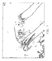
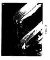
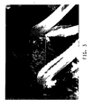
- Figures 1-3 shows a sequence of pictures of a single wipe of one orifice.
- Figure 1 shows the wire (going down vertically) just before it contacted the flowing polyamide. The die drips appear as the white appearing (they are solidified) material somewhat parallel to the flowing molten polymer.
- Figure 2 shows the wire in the midst of the extrudate stream.
- Figure 3 shows the wire just after it exited the polymer stream. The descriptions for Figures 1-3 refer to the right hand polymer stream. Note that in Figure 3 the die drip is now attached to the wire and is being carried away from the orifice and extrudate stream. Sometimes the wire dislodges the die drip and it may stick to the wire, or drop away, or become attached to the polymer stream and be carried along with the polymer.
- the polyamide was being extruded into a strand to be chopped.
- the wire was moved through the polyamide stream the strands were not broken or interrupted.
- the polyamide simply flowed around the wire and the flows rejoined on the downstream side of the wire.
- Example 2 the die used as similar to that used in Example 1, i.e., it had two circular holes 0.48 cm in diameter.
- the extruder was a 30 mm Werner & Pfleiderer twin screw extruder.
- the composition extruded was Rynite® 530, a poly(ethylene terephthalate) containing 30 weight percent of chopped glass fiber and minor amounts of other materials (stabilizers, crystallization promoters, etc.) available from E.I. DuPont de Nemours & Co., Inc. Wilmington, DE 19898, USA.
- the composition was dried under manufacturer recommended conditions before use.
- the extruder barrels and die were set at 310°C, and the composition was extruded at an approximate rate (total of both holes) of 18 kg/h.
- the wire used was mounted as described in Example 1. It was a stainless steel wire with a diameter of 0.13 mm. It was passed vertically (up and down) or horizontally through the polymer streams as described in Example 1 and successfully removed the die drips without interrupting the polymer flow. However if the wire were passed too rapidly through the polymer stream the polymer flow was interrupted, so slower "traverse speeds" were desirable. A typical useful speed was about 3.1 mm/sec across the face of the die. It was noticed on video of these wipes that a section of the polymer composition stream sometimes separated from the main polymer stream. When a stainless steel wire with a 0.23 mm diameter was used the flow of the polymer stream was more "disturbed” but the wiping could still be done without interrupting the polymer stream.
- Example 2 The same conditions were used as in Example 2 with the 0.13 mm diameter wire except the barrel and die temperatures were 330°C, and the polymer composition used was Zenite® HX6130, a liquid crystalline polyester polymer containing 30 weight percent chopped glass fiber, available from E.I. DuPont de Nemours & Co., Inc., Wilmington, DE 19898, USA. Again when the wire was passed through the polymer streams vertically (up and down) or horizontally it smoothly removed the die drips without interruption of the polymer streams.
- Zenite® HX6130 a liquid crystalline polyester polymer containing 30 weight percent chopped glass fiber
Landscapes
- Engineering & Computer Science (AREA)
- Mechanical Engineering (AREA)
- Extrusion Moulding Of Plastics Or The Like (AREA)
- Processing And Handling Of Plastics And Other Materials For Molding In General (AREA)
Applications Claiming Priority (2)
| Application Number | Priority Date | Filing Date | Title |
|---|---|---|---|
| US85392306P | 2006-10-24 | 2006-10-24 | |
| PCT/US2007/022420 WO2008051515A2 (en) | 2006-10-24 | 2007-10-22 | Process and apparatus for cleaning extruder dies |
Publications (2)
| Publication Number | Publication Date |
|---|---|
| EP2086742A2 EP2086742A2 (en) | 2009-08-12 |
| EP2086742B1 true EP2086742B1 (en) | 2012-06-13 |
Family
ID=39264512
Family Applications (1)
| Application Number | Title | Priority Date | Filing Date |
|---|---|---|---|
| EP07852884A Not-in-force EP2086742B1 (en) | 2006-10-24 | 2007-10-22 | Process and apparatus for cleaning extruder dies |
Country Status (5)
| Country | Link |
|---|---|
| US (1) | US8297964B2 (enExample) |
| EP (1) | EP2086742B1 (enExample) |
| JP (1) | JP5298024B2 (enExample) |
| CA (1) | CA2663038A1 (enExample) |
| WO (1) | WO2008051515A2 (enExample) |
Families Citing this family (4)
| Publication number | Priority date | Publication date | Assignee | Title |
|---|---|---|---|---|
| WO2012167802A1 (de) | 2011-06-07 | 2012-12-13 | Mauser-Werke Gmbh | Verfahren und vorrichtung zur abreinigung eines extrusionskopfs |
| JP6308789B2 (ja) * | 2014-01-29 | 2018-04-11 | 兵神装備株式会社 | ノズル、塗布装置、及び流動物の塗布方法 |
| US11065817B2 (en) | 2018-08-14 | 2021-07-20 | Massivit 3D Printing Technologies Ltd. | Extrusion orifice cleaning |
| EP4377062A1 (en) | 2021-07-27 | 2024-06-05 | ExxonMobil Chemical Patents Inc. | Systems and methods of cleaning extruders |
Family Cites Families (6)
| Publication number | Priority date | Publication date | Assignee | Title |
|---|---|---|---|---|
| JP3301875B2 (ja) * | 1994-11-28 | 2002-07-15 | 三菱化学株式会社 | ストランド成形機のダイプレート清浄装置 |
| JP3699539B2 (ja) * | 1996-07-11 | 2005-09-28 | 東芝機械株式会社 | 押出成形用tダイ |
| US6164948A (en) * | 1998-05-08 | 2000-12-26 | Kimberly-Clark Worldwide, Inc. | Extrusion die system with removable insert |
| JP2000025089A (ja) * | 1998-07-13 | 2000-01-25 | Sumitomo Heavy Ind Ltd | Tダイ装置のリップ下面清掃装置 |
| US7074030B2 (en) * | 2002-09-23 | 2006-07-11 | Extrusion Dies Industries, Llc. | Scraping assembly for an extrusion die and method of use therefor |
| ITBO20020683A1 (it) * | 2002-10-31 | 2004-05-01 | Sacmi | Dispositivo per il prelievo di dosi di materiale plastico da un estrusore |
-
2007
- 2007-10-19 US US11/975,415 patent/US8297964B2/en not_active Expired - Fee Related
- 2007-10-22 JP JP2009534612A patent/JP5298024B2/ja not_active Expired - Fee Related
- 2007-10-22 WO PCT/US2007/022420 patent/WO2008051515A2/en not_active Ceased
- 2007-10-22 CA CA002663038A patent/CA2663038A1/en not_active Abandoned
- 2007-10-22 EP EP07852884A patent/EP2086742B1/en not_active Not-in-force
Also Published As
| Publication number | Publication date |
|---|---|
| CA2663038A1 (en) | 2008-05-02 |
| WO2008051515A2 (en) | 2008-05-02 |
| JP2010507512A (ja) | 2010-03-11 |
| EP2086742A2 (en) | 2009-08-12 |
| US8297964B2 (en) | 2012-10-30 |
| JP5298024B2 (ja) | 2013-09-25 |
| WO2008051515A3 (en) | 2008-06-19 |
| US20080099940A1 (en) | 2008-05-01 |
Similar Documents
| Publication | Publication Date | Title |
|---|---|---|
| EP2086742B1 (en) | Process and apparatus for cleaning extruder dies | |
| CN102202852B (zh) | 用于聚合物的挤出喷嘴 | |
| JP5584208B2 (ja) | 樹脂押出用ダイ及びそれを用いた押出成形方法 | |
| JP5638882B2 (ja) | 熱可塑性樹脂組成物の押出成形方法 | |
| US4530649A (en) | Apparatus for feeding of molten strands to a drainage trough | |
| JP2011500379A (ja) | プラスチック材料からペレットを製造するための装置、およびこれを動作させる方法 | |
| JP2012232432A (ja) | 樹脂押出用ダイ | |
| JP2011173269A (ja) | 熱可塑性樹脂ペレットの製造装置およびその製造方法 | |
| JP2008508118A (ja) | ポリ(アリーレンエーテル)ブレンドの押出装置及び方法 | |
| JP2003136579A (ja) | 樹脂押出機ダイ装置及び押出成形方法 | |
| JP2012056145A (ja) | 熱可塑性樹脂組成物の押出成形方法 | |
| JP4470380B2 (ja) | ストランドカッターおよびそれを用いたペレットの製造方法 | |
| KR100671216B1 (ko) | 합성수지시트 제조장치 및 그에 사용되는 롤러 | |
| JP2687807B2 (ja) | 成形用樹脂組成物の吐出方法 | |
| JP3621851B2 (ja) | 押出成形用ダイ及びそれを用いた熱可塑性樹脂フィルムの製造方法 | |
| JP5728077B2 (ja) | 熱可塑性樹脂組成物ペレットの製造方法、押出機及びダイプレート | |
| JP7426450B1 (ja) | ガラス繊維強化ポリアミド樹脂組成物の製造方法 | |
| JP2000043036A (ja) | 成形用樹脂材料の製造方法および装置 | |
| US3733153A (en) | Apparatus for minimizing strand drop-off | |
| JPH11254430A (ja) | 成形用樹脂材の製造方法及び装置 | |
| JP7426451B1 (ja) | ガラス繊維強化ポリアミド樹脂組成物の製造方法 | |
| JP2004188613A (ja) | 樹脂ペレットの製造装置および製造方法 | |
| JP2004268521A (ja) | 樹脂成形品の製造方法およびダイの目ヤニ除去装置 | |
| US20060021948A1 (en) | Apparatus and process for extruding poly(arylene ether) blends | |
| CN104114347A (zh) | 用于使聚合物组合物拉条造粒的模具和方法 |
Legal Events
| Date | Code | Title | Description |
|---|---|---|---|
| PUAI | Public reference made under article 153(3) epc to a published international application that has entered the european phase |
Free format text: ORIGINAL CODE: 0009012 |
|
| 17P | Request for examination filed |
Effective date: 20090527 |
|
| AK | Designated contracting states |
Kind code of ref document: A2 Designated state(s): AT BE BG CH CY CZ DE DK EE ES FI FR GB GR HU IE IS IT LI LT LU LV MC MT NL PL PT RO SE SI SK TR |
|
| 17Q | First examination report despatched |
Effective date: 20090821 |
|
| DAX | Request for extension of the european patent (deleted) | ||
| R17P | Request for examination filed (corrected) |
Effective date: 20090513 |
|
| GRAP | Despatch of communication of intention to grant a patent |
Free format text: ORIGINAL CODE: EPIDOSNIGR1 |
|
| GRAS | Grant fee paid |
Free format text: ORIGINAL CODE: EPIDOSNIGR3 |
|
| GRAA | (expected) grant |
Free format text: ORIGINAL CODE: 0009210 |
|
| AK | Designated contracting states |
Kind code of ref document: B1 Designated state(s): AT BE BG CH CY CZ DE DK EE ES FI FR GB GR HU IE IS IT LI LT LU LV MC MT NL PL PT RO SE SI SK TR |
|
| REG | Reference to a national code |
Ref country code: GB Ref legal event code: FG4D |
|
| REG | Reference to a national code |
Ref country code: AT Ref legal event code: REF Ref document number: 561788 Country of ref document: AT Kind code of ref document: T Effective date: 20120615 Ref country code: CH Ref legal event code: EP |
|
| REG | Reference to a national code |
Ref country code: IE Ref legal event code: FG4D |
|
| REG | Reference to a national code |
Ref country code: DE Ref legal event code: R096 Ref document number: 602007023436 Country of ref document: DE Effective date: 20120809 |
|
| REG | Reference to a national code |
Ref country code: NL Ref legal event code: VDEP Effective date: 20120613 |
|
| PG25 | Lapsed in a contracting state [announced via postgrant information from national office to epo] |
Ref country code: CY Free format text: LAPSE BECAUSE OF FAILURE TO SUBMIT A TRANSLATION OF THE DESCRIPTION OR TO PAY THE FEE WITHIN THE PRESCRIBED TIME-LIMIT Effective date: 20120613 Ref country code: SE Free format text: LAPSE BECAUSE OF FAILURE TO SUBMIT A TRANSLATION OF THE DESCRIPTION OR TO PAY THE FEE WITHIN THE PRESCRIBED TIME-LIMIT Effective date: 20120613 Ref country code: FI Free format text: LAPSE BECAUSE OF FAILURE TO SUBMIT A TRANSLATION OF THE DESCRIPTION OR TO PAY THE FEE WITHIN THE PRESCRIBED TIME-LIMIT Effective date: 20120613 Ref country code: LT Free format text: LAPSE BECAUSE OF FAILURE TO SUBMIT A TRANSLATION OF THE DESCRIPTION OR TO PAY THE FEE WITHIN THE PRESCRIBED TIME-LIMIT Effective date: 20120613 |
|
| REG | Reference to a national code |
Ref country code: AT Ref legal event code: MK05 Ref document number: 561788 Country of ref document: AT Kind code of ref document: T Effective date: 20120613 |
|
| REG | Reference to a national code |
Ref country code: LT Ref legal event code: MG4D Effective date: 20120613 |
|
| PG25 | Lapsed in a contracting state [announced via postgrant information from national office to epo] |
Ref country code: LV Free format text: LAPSE BECAUSE OF FAILURE TO SUBMIT A TRANSLATION OF THE DESCRIPTION OR TO PAY THE FEE WITHIN THE PRESCRIBED TIME-LIMIT Effective date: 20120613 Ref country code: GR Free format text: LAPSE BECAUSE OF FAILURE TO SUBMIT A TRANSLATION OF THE DESCRIPTION OR TO PAY THE FEE WITHIN THE PRESCRIBED TIME-LIMIT Effective date: 20120914 Ref country code: SI Free format text: LAPSE BECAUSE OF FAILURE TO SUBMIT A TRANSLATION OF THE DESCRIPTION OR TO PAY THE FEE WITHIN THE PRESCRIBED TIME-LIMIT Effective date: 20120613 |
|
| PG25 | Lapsed in a contracting state [announced via postgrant information from national office to epo] |
Ref country code: AT Free format text: LAPSE BECAUSE OF FAILURE TO SUBMIT A TRANSLATION OF THE DESCRIPTION OR TO PAY THE FEE WITHIN THE PRESCRIBED TIME-LIMIT Effective date: 20120613 Ref country code: BE Free format text: LAPSE BECAUSE OF FAILURE TO SUBMIT A TRANSLATION OF THE DESCRIPTION OR TO PAY THE FEE WITHIN THE PRESCRIBED TIME-LIMIT Effective date: 20120613 Ref country code: CZ Free format text: LAPSE BECAUSE OF FAILURE TO SUBMIT A TRANSLATION OF THE DESCRIPTION OR TO PAY THE FEE WITHIN THE PRESCRIBED TIME-LIMIT Effective date: 20120613 Ref country code: RO Free format text: LAPSE BECAUSE OF FAILURE TO SUBMIT A TRANSLATION OF THE DESCRIPTION OR TO PAY THE FEE WITHIN THE PRESCRIBED TIME-LIMIT Effective date: 20120613 Ref country code: SK Free format text: LAPSE BECAUSE OF FAILURE TO SUBMIT A TRANSLATION OF THE DESCRIPTION OR TO PAY THE FEE WITHIN THE PRESCRIBED TIME-LIMIT Effective date: 20120613 Ref country code: IS Free format text: LAPSE BECAUSE OF FAILURE TO SUBMIT A TRANSLATION OF THE DESCRIPTION OR TO PAY THE FEE WITHIN THE PRESCRIBED TIME-LIMIT Effective date: 20121013 Ref country code: EE Free format text: LAPSE BECAUSE OF FAILURE TO SUBMIT A TRANSLATION OF THE DESCRIPTION OR TO PAY THE FEE WITHIN THE PRESCRIBED TIME-LIMIT Effective date: 20120613 |
|
| PGFP | Annual fee paid to national office [announced via postgrant information from national office to epo] |
Ref country code: DE Payment date: 20121017 Year of fee payment: 6 Ref country code: FR Payment date: 20121018 Year of fee payment: 6 |
|
| PG25 | Lapsed in a contracting state [announced via postgrant information from national office to epo] |
Ref country code: PT Free format text: LAPSE BECAUSE OF FAILURE TO SUBMIT A TRANSLATION OF THE DESCRIPTION OR TO PAY THE FEE WITHIN THE PRESCRIBED TIME-LIMIT Effective date: 20121015 Ref country code: IT Free format text: LAPSE BECAUSE OF FAILURE TO SUBMIT A TRANSLATION OF THE DESCRIPTION OR TO PAY THE FEE WITHIN THE PRESCRIBED TIME-LIMIT Effective date: 20120613 Ref country code: PL Free format text: LAPSE BECAUSE OF FAILURE TO SUBMIT A TRANSLATION OF THE DESCRIPTION OR TO PAY THE FEE WITHIN THE PRESCRIBED TIME-LIMIT Effective date: 20120613 |
|
| PG25 | Lapsed in a contracting state [announced via postgrant information from national office to epo] |
Ref country code: NL Free format text: LAPSE BECAUSE OF FAILURE TO SUBMIT A TRANSLATION OF THE DESCRIPTION OR TO PAY THE FEE WITHIN THE PRESCRIBED TIME-LIMIT Effective date: 20120613 |
|
| PLBE | No opposition filed within time limit |
Free format text: ORIGINAL CODE: 0009261 |
|
| STAA | Information on the status of an ep patent application or granted ep patent |
Free format text: STATUS: NO OPPOSITION FILED WITHIN TIME LIMIT |
|
| PG25 | Lapsed in a contracting state [announced via postgrant information from national office to epo] |
Ref country code: DK Free format text: LAPSE BECAUSE OF FAILURE TO SUBMIT A TRANSLATION OF THE DESCRIPTION OR TO PAY THE FEE WITHIN THE PRESCRIBED TIME-LIMIT Effective date: 20120613 Ref country code: ES Free format text: LAPSE BECAUSE OF FAILURE TO SUBMIT A TRANSLATION OF THE DESCRIPTION OR TO PAY THE FEE WITHIN THE PRESCRIBED TIME-LIMIT Effective date: 20120924 |
|
| 26N | No opposition filed |
Effective date: 20130314 |
|
| PG25 | Lapsed in a contracting state [announced via postgrant information from national office to epo] |
Ref country code: MC Free format text: LAPSE BECAUSE OF NON-PAYMENT OF DUE FEES Effective date: 20121031 |
|
| REG | Reference to a national code |
Ref country code: CH Ref legal event code: PL |
|
| GBPC | Gb: european patent ceased through non-payment of renewal fee |
Effective date: 20121022 |
|
| REG | Reference to a national code |
Ref country code: DE Ref legal event code: R097 Ref document number: 602007023436 Country of ref document: DE Effective date: 20130314 |
|
| REG | Reference to a national code |
Ref country code: IE Ref legal event code: MM4A |
|
| PG25 | Lapsed in a contracting state [announced via postgrant information from national office to epo] |
Ref country code: CH Free format text: LAPSE BECAUSE OF NON-PAYMENT OF DUE FEES Effective date: 20121031 Ref country code: IE Free format text: LAPSE BECAUSE OF NON-PAYMENT OF DUE FEES Effective date: 20121022 Ref country code: BG Free format text: LAPSE BECAUSE OF FAILURE TO SUBMIT A TRANSLATION OF THE DESCRIPTION OR TO PAY THE FEE WITHIN THE PRESCRIBED TIME-LIMIT Effective date: 20120913 Ref country code: GB Free format text: LAPSE BECAUSE OF NON-PAYMENT OF DUE FEES Effective date: 20121022 Ref country code: LI Free format text: LAPSE BECAUSE OF NON-PAYMENT OF DUE FEES Effective date: 20121031 |
|
| PG25 | Lapsed in a contracting state [announced via postgrant information from national office to epo] |
Ref country code: MT Free format text: LAPSE BECAUSE OF FAILURE TO SUBMIT A TRANSLATION OF THE DESCRIPTION OR TO PAY THE FEE WITHIN THE PRESCRIBED TIME-LIMIT Effective date: 20120613 |
|
| PG25 | Lapsed in a contracting state [announced via postgrant information from national office to epo] |
Ref country code: TR Free format text: LAPSE BECAUSE OF FAILURE TO SUBMIT A TRANSLATION OF THE DESCRIPTION OR TO PAY THE FEE WITHIN THE PRESCRIBED TIME-LIMIT Effective date: 20120613 |
|
| PG25 | Lapsed in a contracting state [announced via postgrant information from national office to epo] |
Ref country code: LU Free format text: LAPSE BECAUSE OF NON-PAYMENT OF DUE FEES Effective date: 20121022 |
|
| PG25 | Lapsed in a contracting state [announced via postgrant information from national office to epo] |
Ref country code: HU Free format text: LAPSE BECAUSE OF FAILURE TO SUBMIT A TRANSLATION OF THE DESCRIPTION OR TO PAY THE FEE WITHIN THE PRESCRIBED TIME-LIMIT Effective date: 20071022 |
|
| REG | Reference to a national code |
Ref country code: DE Ref legal event code: R119 Ref document number: 602007023436 Country of ref document: DE Effective date: 20140501 |
|
| REG | Reference to a national code |
Ref country code: FR Ref legal event code: ST Effective date: 20140630 |
|
| PG25 | Lapsed in a contracting state [announced via postgrant information from national office to epo] |
Ref country code: FR Free format text: LAPSE BECAUSE OF NON-PAYMENT OF DUE FEES Effective date: 20131031 Ref country code: DE Free format text: LAPSE BECAUSE OF NON-PAYMENT OF DUE FEES Effective date: 20140501 |