EP2086196A2 - MIMO-Kommunikationssystem und Übertragungsstation - Google Patents
MIMO-Kommunikationssystem und Übertragungsstation Download PDFInfo
- Publication number
- EP2086196A2 EP2086196A2 EP08171370A EP08171370A EP2086196A2 EP 2086196 A2 EP2086196 A2 EP 2086196A2 EP 08171370 A EP08171370 A EP 08171370A EP 08171370 A EP08171370 A EP 08171370A EP 2086196 A2 EP2086196 A2 EP 2086196A2
- Authority
- EP
- European Patent Office
- Prior art keywords
- transmission
- matrix
- matrix obtained
- equation
- station
- Prior art date
- Legal status (The legal status is an assumption and is not a legal conclusion. Google has not performed a legal analysis and makes no representation as to the accuracy of the status listed.)
- Granted
Links
Images


Classifications
-
- H—ELECTRICITY
- H04—ELECTRIC COMMUNICATION TECHNIQUE
- H04L—TRANSMISSION OF DIGITAL INFORMATION, e.g. TELEGRAPHIC COMMUNICATION
- H04L27/00—Modulated-carrier systems
- H04L27/26—Systems using multi-frequency codes
- H04L27/2601—Multicarrier modulation systems
- H04L27/2614—Peak power aspects
- H04L27/2615—Reduction thereof using coding
- H04L27/2617—Reduction thereof using coding using block codes
-
- H—ELECTRICITY
- H04—ELECTRIC COMMUNICATION TECHNIQUE
- H04B—TRANSMISSION
- H04B7/00—Radio transmission systems, i.e. using radiation field
- H04B7/02—Diversity systems; Multi-antenna system, i.e. transmission or reception using multiple antennas
- H04B7/04—Diversity systems; Multi-antenna system, i.e. transmission or reception using multiple antennas using two or more spaced independent antennas
- H04B7/0404—Diversity systems; Multi-antenna system, i.e. transmission or reception using multiple antennas using two or more spaced independent antennas the mobile station comprising multiple antennas, e.g. to provide uplink diversity
-
- H—ELECTRICITY
- H04—ELECTRIC COMMUNICATION TECHNIQUE
- H04B—TRANSMISSION
- H04B7/00—Radio transmission systems, i.e. using radiation field
- H04B7/02—Diversity systems; Multi-antenna system, i.e. transmission or reception using multiple antennas
- H04B7/04—Diversity systems; Multi-antenna system, i.e. transmission or reception using multiple antennas using two or more spaced independent antennas
- H04B7/0413—MIMO systems
- H04B7/0417—Feedback systems
-
- H—ELECTRICITY
- H04—ELECTRIC COMMUNICATION TECHNIQUE
- H04B—TRANSMISSION
- H04B7/00—Radio transmission systems, i.e. using radiation field
- H04B7/02—Diversity systems; Multi-antenna system, i.e. transmission or reception using multiple antennas
- H04B7/04—Diversity systems; Multi-antenna system, i.e. transmission or reception using multiple antennas using two or more spaced independent antennas
- H04B7/0413—MIMO systems
- H04B7/0426—Power distribution
-
- H—ELECTRICITY
- H04—ELECTRIC COMMUNICATION TECHNIQUE
- H04B—TRANSMISSION
- H04B7/00—Radio transmission systems, i.e. using radiation field
- H04B7/02—Diversity systems; Multi-antenna system, i.e. transmission or reception using multiple antennas
- H04B7/04—Diversity systems; Multi-antenna system, i.e. transmission or reception using multiple antennas using two or more spaced independent antennas
- H04B7/06—Diversity systems; Multi-antenna system, i.e. transmission or reception using multiple antennas using two or more spaced independent antennas at the transmitting station
- H04B7/0613—Diversity systems; Multi-antenna system, i.e. transmission or reception using multiple antennas using two or more spaced independent antennas at the transmitting station using simultaneous transmission
- H04B7/0615—Diversity systems; Multi-antenna system, i.e. transmission or reception using multiple antennas using two or more spaced independent antennas at the transmitting station using simultaneous transmission of weighted versions of same signal
- H04B7/0665—Feed forward of transmit weights to the receiver
-
- H—ELECTRICITY
- H04—ELECTRIC COMMUNICATION TECHNIQUE
- H04L—TRANSMISSION OF DIGITAL INFORMATION, e.g. TELEGRAPHIC COMMUNICATION
- H04L25/00—Baseband systems
- H04L25/02—Details ; arrangements for supplying electrical power along data transmission lines
- H04L25/03—Shaping networks in transmitter or receiver, e.g. adaptive shaping networks
- H04L25/03006—Arrangements for removing intersymbol interference
- H04L25/03343—Arrangements at the transmitter end
-
- H—ELECTRICITY
- H04—ELECTRIC COMMUNICATION TECHNIQUE
- H04L—TRANSMISSION OF DIGITAL INFORMATION, e.g. TELEGRAPHIC COMMUNICATION
- H04L5/00—Arrangements affording multiple use of the transmission path
- H04L5/003—Arrangements for allocating sub-channels of the transmission path
- H04L5/0044—Allocation of payload; Allocation of data channels, e.g. PDSCH or PUSCH
-
- H—ELECTRICITY
- H04—ELECTRIC COMMUNICATION TECHNIQUE
- H04B—TRANSMISSION
- H04B7/00—Radio transmission systems, i.e. using radiation field
- H04B7/02—Diversity systems; Multi-antenna system, i.e. transmission or reception using multiple antennas
- H04B7/04—Diversity systems; Multi-antenna system, i.e. transmission or reception using multiple antennas using two or more spaced independent antennas
- H04B7/06—Diversity systems; Multi-antenna system, i.e. transmission or reception using multiple antennas using two or more spaced independent antennas at the transmitting station
- H04B7/0613—Diversity systems; Multi-antenna system, i.e. transmission or reception using multiple antennas using two or more spaced independent antennas at the transmitting station using simultaneous transmission
- H04B7/0615—Diversity systems; Multi-antenna system, i.e. transmission or reception using multiple antennas using two or more spaced independent antennas at the transmitting station using simultaneous transmission of weighted versions of same signal
- H04B7/0619—Diversity systems; Multi-antenna system, i.e. transmission or reception using multiple antennas using two or more spaced independent antennas at the transmitting station using simultaneous transmission of weighted versions of same signal using feedback from receiving side
- H04B7/0621—Feedback content
- H04B7/0634—Antenna weights or vector/matrix coefficients
-
- H—ELECTRICITY
- H04—ELECTRIC COMMUNICATION TECHNIQUE
- H04B—TRANSMISSION
- H04B7/00—Radio transmission systems, i.e. using radiation field
- H04B7/02—Diversity systems; Multi-antenna system, i.e. transmission or reception using multiple antennas
- H04B7/04—Diversity systems; Multi-antenna system, i.e. transmission or reception using multiple antennas using two or more spaced independent antennas
- H04B7/06—Diversity systems; Multi-antenna system, i.e. transmission or reception using multiple antennas using two or more spaced independent antennas at the transmitting station
- H04B7/0613—Diversity systems; Multi-antenna system, i.e. transmission or reception using multiple antennas using two or more spaced independent antennas at the transmitting station using simultaneous transmission
- H04B7/0615—Diversity systems; Multi-antenna system, i.e. transmission or reception using multiple antennas using two or more spaced independent antennas at the transmitting station using simultaneous transmission of weighted versions of same signal
- H04B7/0619—Diversity systems; Multi-antenna system, i.e. transmission or reception using multiple antennas using two or more spaced independent antennas at the transmitting station using simultaneous transmission of weighted versions of same signal using feedback from receiving side
- H04B7/0636—Feedback format
- H04B7/0639—Using selective indices, e.g. of a codebook, e.g. pre-distortion matrix index [PMI] or for beam selection
-
- H—ELECTRICITY
- H04—ELECTRIC COMMUNICATION TECHNIQUE
- H04L—TRANSMISSION OF DIGITAL INFORMATION, e.g. TELEGRAPHIC COMMUNICATION
- H04L25/00—Baseband systems
- H04L25/02—Details ; arrangements for supplying electrical power along data transmission lines
- H04L25/03—Shaping networks in transmitter or receiver, e.g. adaptive shaping networks
- H04L25/03006—Arrangements for removing intersymbol interference
- H04L2025/0335—Arrangements for removing intersymbol interference characterised by the type of transmission
- H04L2025/03375—Passband transmission
- H04L2025/03414—Multicarrier
-
- H—ELECTRICITY
- H04—ELECTRIC COMMUNICATION TECHNIQUE
- H04L—TRANSMISSION OF DIGITAL INFORMATION, e.g. TELEGRAPHIC COMMUNICATION
- H04L25/00—Baseband systems
- H04L25/02—Details ; arrangements for supplying electrical power along data transmission lines
- H04L25/03—Shaping networks in transmitter or receiver, e.g. adaptive shaping networks
- H04L25/03006—Arrangements for removing intersymbol interference
- H04L2025/0335—Arrangements for removing intersymbol interference characterised by the type of transmission
- H04L2025/03426—Arrangements for removing intersymbol interference characterised by the type of transmission transmission using multiple-input and multiple-output channels
-
- H—ELECTRICITY
- H04—ELECTRIC COMMUNICATION TECHNIQUE
- H04L—TRANSMISSION OF DIGITAL INFORMATION, e.g. TELEGRAPHIC COMMUNICATION
- H04L25/00—Baseband systems
- H04L25/02—Details ; arrangements for supplying electrical power along data transmission lines
- H04L25/03—Shaping networks in transmitter or receiver, e.g. adaptive shaping networks
- H04L25/03006—Arrangements for removing intersymbol interference
- H04L2025/03777—Arrangements for removing intersymbol interference characterised by the signalling
- H04L2025/03802—Signalling on the reverse channel
-
- H—ELECTRICITY
- H04—ELECTRIC COMMUNICATION TECHNIQUE
- H04L—TRANSMISSION OF DIGITAL INFORMATION, e.g. TELEGRAPHIC COMMUNICATION
- H04L27/00—Modulated-carrier systems
- H04L27/26—Systems using multi-frequency codes
- H04L27/2601—Multicarrier modulation systems
- H04L27/2614—Peak power aspects
- H04L27/262—Reduction thereof by selection of pilot symbols
-
- H—ELECTRICITY
- H04—ELECTRIC COMMUNICATION TECHNIQUE
- H04L—TRANSMISSION OF DIGITAL INFORMATION, e.g. TELEGRAPHIC COMMUNICATION
- H04L5/00—Arrangements affording multiple use of the transmission path
- H04L5/003—Arrangements for allocating sub-channels of the transmission path
- H04L5/0048—Allocation of pilot signals, i.e. of signals known to the receiver
Definitions
- the embodiment(s) discussed herein is directed to a MIMO communication system and a transmission station.
- the embodiments are preferable in the case in which, for example, a precoding multi-input multi-output (MIMO) system is applied to an uplink communication in a mobile wireless communication system.
- MIMO multi-input multi-output
- a precoding MIMO system has been examined in an long term evolution (LTE) specification examined in 3rd generation partnership project (3GPP) as a third generation mobile wireless communication system.
- LTE long term evolution
- 3GPP 3rd generation partnership project
- predetermined a plurality of sets of precoding matrix (PM) (hereinafter referred to as "code book") are defined.
- a reception station selects the precoding matrix, by which the most excellent reception property is achieved, by using a known signal (reference signal), and informs this information (index) of the transmission station.
- the transmission station selects the precoding matrix based on the index informed from the reception station, multiplies the transmission signal by the precoding matrix (the element of the precoding matrix) (as a weighing factor), and transmits the resultant.
- the throughput of the wireless communication from the transmission station to the reception station can be enhanced.
- the optimum number of data pieces (number of streams) simultaneously transmitted from the transmission station to the reception station can be selected.
- the number of streams may sometimes be referred to as a rank, and the selection of the optimum rank may sometimes be referred to as a rank adaptation.
- the UE selects the PM, by which it is estimated that the most excellent reception property is obtained, among 64 types of PMs, and reports this number (index) to the base station.
- the base station carries out a downlink transmission by using the PM having the reported number.
- V L,M,N represents the Nth PM in the combination (code book) of the PM of L ⁇ M matrix, when the number of the transmission antennas is defined as L (L is an integer of 2 or more), and the number of transmission streams (ranks) is defined as M (M is an integer of 1 or more).
- the 2 ⁇ 2 matrixes in the equation (2) are unitary matrixes, and the 2 ⁇ 1 matrixes in the equation (1) correspond to the extracted column components in each unitary matrix. Since the value by which the total transmission power becomes 1 is multiplied as a normalized coefficient, the 2 ⁇ 1 matrixes are those of constant multiple of the unitary matrixes, to be correct.
- 4 ⁇ 4 matrixes (16 types) in the case of rank 4 are the unitary matrixes, and 4 ⁇ 3 matrixes in the case of rank 3, 4 ⁇ 2 matrixes in the case of rank 2, and 4 ⁇ 1 matrixes in the case of rank 1 respectively correspond to the extracted column components in each unitary matrix.
- the matrixes of PM other than the rank 1 are mutually orthogonal.
- reducing power consumption of UE is important.
- the enhancement in the power efficiency of an amplifier for a transmission signal of the UE is effective for reducing the power consumption.
- PAPR peak to average power ratio
- orthogonal frequency division multiplexing (OFDM) system has been proposed as a wireless access system that is strong for a frequency selective fading in a multi-pass in a broadband radio communication.
- OFDM orthogonal frequency division multiplexing
- this system employs a multi-carrier transmission, so that the PAPR of the transmission signal tends to increase. From the viewpoint of the power efficiency of the UE, it is unsuitable for the transmission system of the uplink (wireless link from the UE to the base station) in the cellular system.
- a transmitter adds a cyclic prefix (CP) to an effective symbol in a time-domain to carry out a single carrier transmission, and a receiver performs a frequency equalization.
- CP cyclic prefix
- SC-FDMA single carrier frequency division multiple access
- transmission data signals or known signals between the transmission and reception are multiplexed in the time-domain, so that it can suppress the PAPR, compared to the OFDM in which the data signals or known signals are multiplexed in the frequency region.
- the PAPR is mostly used as an index of evaluating the back-off necessary for the design of the amplifier, but an evaluation index of raw Cubic Metric (raw CM) represented by the following equation (3) is also proposed in the following Motorola, "Comparison of PAR and Cubic Metric for Power De-rating" (R1-040642, TSG RAN WG1 #37), 2004. 5 described below.
- the relative back-off can be defined by the following equation (4) by using the raw CM.
- CM Cubic Metric
- the application of the precoding MIMO system is only examined with respect to the downlink (DL) communication (multi-carrier transmission), in which the increase of the PAPR is not a problem, compared to the UE.
- DL downlink
- precoding MIMO system it is desirable to suppress the increase in the PAPR when the precoding MIMO system is applied to, for example, a single carrier transmission (UL communication in a mobile communication system).
- MIMO communication system and transmission station In order to achieve the foregoing desirable features, the present specification describes a following "MIMO communication system and transmission station".
- the increase in the PAPR can be suppressed when the precoding MIMO system is applied to the communication in the direction (uplink) from the UE, which is one example of the transmission station, to the base station, which is one example of the reception station.
- the transmission signals are multiplexed for every transmission antenna in the case other than the case of the rank 1.
- the PAPR or raw CM
- a unitary matrix U in which the imbalanced amplitude between the components in the rows (between the elements in the columns) is made variable is used for the precoding matrix (PM) that is multiplied by the plurality of transmission streams of the UL.
- the amplitude is made variable depending upon the characteristic of the amplifier or the transmission power of the UE. As illustrated below, the PAPR can be reduced as the imbalanced amplitude is reduced.
- the PM may be the matrix obtained by rearranging the components in the row in the matrix expressed by the equation (6), the matrix obtained by rearranging the components in the column in the matrix expressed by the equation (6), or the matrix obtained by rearranging the components in the column and row in the matrix expressed by the equation (6).
- the raw CM can be decreased.
- the effect of the precoding MIMO becomes small as ⁇ is decreased.
- the throughput property corresponding to the case where the precoding MIMO is not carried out is obtained.
- the raw CM corresponding to the conventional case is obtained.
- the raw CM increases to 5.46 [dB] with respect to 3.39 [dB] in QPSK in a single stream, while increases to 6.18 [dB] with respect to 4.8 [dB] in 16 QAM.
- the set of PM may be common to the UE in the system, or may differ for a part of or all UEs.
- the UE can autonomously select the preferable or optimum ⁇ based on the property of the amplifier of the own station or the current transmission power, and can report the selected ⁇ to the base station.
- the base station controls the transmission power of UE (P UE ) in such a manner that the transmission power of the UE located at the position close to the cell end (remote from the base station) becomes greater than the transmission power of the UE located at the position close to the center of the cell (close to the base station).
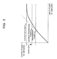
- the back-off of the UE located at the center of the cell is apparently relatively greater than the back-off of the UE located at the cell end, so that the UE located at the center of the cell can transmit a signal having a greater raw CM (e.g., see FIG. 3 ).
- the UE having relatively a great back-off and affording a transmission power can select a greater ⁇ .
- the throughput of the UL according to the precoding MIMO can be enhanced.
- the transmission power P UE (the maximum transmission power P max ) that can be transmitted from the UE without causing the distortion at the amplifier can be expressed by, for example, P UE (P max ) ⁇ P sat - CM [dB], wherein the saturation power of the amplifier is defined as Psat, and the value calculated from the equation (4) (back-off) is defined as CM (see FIG. 3 ).
- the value of the CM is determined according to the characteristic of the amplifier and the property of the transmission signal.
- the transmission power P UE of the UE is sometimes controlled from the base station as described above.
- the optimum value of ⁇ can be defined as the maximum ⁇ that satisfies the following equation (7), for example.
- the CM( ⁇ ) means that the CM is the function of ⁇ . P sat ⁇ P UE + CM ⁇
- the case in which the number of the transmission antenna is greater than 2 is considered. If the transmission signal is multiplexed more than 2 streams per one transmission antenna, the CM might remarkably increase. Therefore, it is preferable to avoid this situation.
- a CN is a normalized coefficient.
- the PM can be formed by the combination of PM in the case where the number of the transmission antenna is 2, as respectively expressed by the following equations (9) and (10).
- ⁇ 2 ⁇ 1 in the equation (9) and ⁇ 2 ⁇ 2 in the equation (10) represent the matrix having a coefficient (it may be 0) sufficiently smaller than ⁇ , and mean that they have dimensions of 2x1 and 2x2 respectively.
- the PM in the case where the number of the transmission antenna is 4 and the rank is 2 may be the matrix obtained by rearranging the components in the row in the matrix obtained from the equation (8), may be the matrix obtained by rearranging the components in the column in the matrix obtained from the equation (8), and may be the matrix obtained by rearranging the components in the row and column in the matrix obtained from the equation (8).
- the PM in the case where the number of the transmission antenna is 4 and the rank is 3 may be the matrix obtained by rearranging the components in the row in the matrix obtained from the equation (9), may be the matrix obtained by rearranging the components in the column in the matrix obtained from the equation (9) , and may be the matrix obtained by rearranging the components in the row and column in the matrix obtained from the equation (9).
- the PM in the case where the number of the transmission antenna is 4 and the rank is 4 may be the matrix obtained by rearranging the components in the row in the matrix obtained from the equation (10), may be the matrix obtained by rearranging the components in the column in the matrix obtained from the equation (10), and may be the matrix obtained by rearranging the components in the row and column in the matrix obtained from the equation (10).
- the PM having the greater dimension can be formed by the combination of U 2,2 ( ⁇ , ⁇ ).
- the PM may be the matrix obtained by rearranging the components in the row in the matrix, may be the matrix obtained by rearranging the components in the column in the matrix, and may be the matrix obtained by rearranging the components in the row and column in the matrix.
- FIG. 1 is a block diagram illustrating an example of a configuration of a MIMO communication system according to an embodiment.
- the system illustrated in FIG. 1 includes, for example, at least one transmission station 10 and at least one reception station 30.
- the transmission station 10 is, for example, an UE
- the reception station 30 is, for example, a base station (BS or eNodeB).
- BS base station
- eNodeB base station
- the transmission station 10 includes, for example, an encoding/modulation unit 11, precoding matrix (PM) multiplying unit 12, code book indicator (CBI) determining unit 13, switch (SW) 14, transmitter 15, dividers 16 and 19, a plurality of (2 in this case) antennas 17 and 18, and receiver 20.
- PM precoding matrix
- CBI code book indicator
- SW switch
- the encoding/modulation unit 11 encodes transmitted data with a predetermined encoding system, and modulates the encoded data with a predetermined modulation system.
- the encoding system include an error correction encoding such as turbo encoding or convolutional encoding.
- the modulation system include a multi-value quadrature modulation system such as QPSK, 16QAM, 64QAM, etc.
- the encoding system and/or modulation system may adaptively be changed (adaptive modulation and coding (AMC) control) according to the environment of propagation path between the reception station 30 and the encoding/modulation unit 11.
- AMC adaptive modulation and coding
- the PM multiplying unit 12 has a code book (memory) 121 holding a plurality of sets of precoding matrix (PM).
- the PM multiplying unit 12 selects the corresponding PM (precoding matrix) from the code book 121 based on the precoding matrix indicator (PMI) reported from the reception station 30, and multiplies the modulation signal sequence obtained from the encoding/modulation unit 11 by the PM (the element of the PM) (as a weighing factor).
- the PMI is received and extracted (detected) by the receiver 20 as a signal of a control channel, for example.
- the code book 121 in the present embodiment holds sets of PM expressed by the equations (8), (9) and (10), i.e., sets of unitary matrix U in which the imbalanced amplitude ⁇ is produced between the elements in each column in the matrix corresponding to the number of the transmission stream.
- the PM multiplying unit 12 has the code book 121, weighing factor control unit (PM setting unit) 122, multipliers 123-1, 123-2, 123-3, and 123-4, and adders 124-1 and 124-2.
- One of the transmission streams is inputted to the multiplier 123-1 and the multiplier 123-2 respectively, wherein the components U 1,1 and U 2,1 in the first column (the element having the imbalanced amplitude ⁇ ) in the precoding matrix (unitary matrix) U selected at the weighing factor control unit 122 are multiplied at the multipliers 123-1 and 123-2 respectively as a weighing factor.
- the other transmission stream is inputted to the remaining multiplier 123-3 and the multiplier 123-4 respectively, wherein the components U 1,2 and U 2,2 in the second column (the element having the imbalanced amplitude ⁇ ) in the precoding matrix (unitary matrix) U are multiplied at the multipliers 123-3 and 123-4 respectively as a weighing factor.
- the result of the multiplication at the multiplier 123-1 and the result of the multiplication at the multiplier 123-2 are added (synthesized) at one adder 124-1, and the result of the multiplication at the remaining multiplier 123-2 and the result of the multiplication of the multiplier 123-4 are added (synthesized) at the other adder 124-2.
- the respective added results are outputted to the switch 14.
- One of the results of the addition is distributed to one antenna 17, while the other one is distributed to the other antenna 18.
- the CBI determining unit 13 determines (selects) the optimum (or preferable) imbalanced amplitude ⁇ .
- the selected ⁇ (or the later-described CBI obtained by quantizing the selected ⁇ ) is reported to the weighing factor control unit 122 of the PM multiplying unit 12, and reflected on the PM in the code book 121 by the control unit 122.
- the weighing factor control unit 122 receives the report of the imbalanced amplitude ⁇ selected at the CBI determining unit 13, whereby it can produce the imbalanced amplitude ⁇ to the set of the weighing factors U 1,1 and U 2,1 or the weighing factors U 1,2 and U 2,2 for the respective transmission streams multiplexed to any of the antennas 17 and 18.
- the ⁇ selected by the CBI determining unit 13 may be the value given for every system or every cell of the reception station 30, which is the base station, or the value given based on the characteristic of the amplifier in the transmitter 15 of each of the transmission stations (UE).
- the maximum ⁇ satisfying the equation (7) is selected beforehand, considering the characteristic of the amplifier of the supposed UE 10 or the maximum transmission power, for example.
- the UE 10 may autonomously select the maximum ⁇ satisfying the equation (7) based on the characteristic of the amplifier, or may adaptively select the maximum ⁇ satisfying the equation (7) according to the current transmission power of the UE 10, additionally or alternatively. Specifically, as the current transmission power P UE of the UE 10 is smaller, the back-off (surplus transmission power) is apparently great, so that a greater ⁇ , e.g., the maximum ⁇ satisfying the equation (7) can be selected. This means that the imbalanced amplitude ⁇ can be controlled in accordance with the transmission power of the UE 10.
- the ⁇ autonomously selected at the UE 10 (the CBI determining unit 13) is preferably reported to the reception station 30 as the signal of the control channel, for example, in order to reflect the ⁇ on the code book 361 of the reception station 30.
- the quantity of the reported information in this case is desirably as smaller as possible from the viewpoint of the saving of the wireless resource (control channel resource) of the UL.
- Quantizing the ⁇ is one example of the techniques for reducing the information quantity.
- FIG. 1 illustrates that the quantized information (index) is reported to the reception station 30 as the code book indicator (CBI).
- the switch 14 selectively outputs the transmission signal, by which the PM is multiplied at the PM multiplying unit 12, and the CBI obtained at the CBI determining unit 13, whereby it outputs the transmission signal and the CBI to the transmitter 15 in a time division multiplexing manner.
- the transmitter 15 performs the transmission process, such as DA conversion, frequency conversion (up-convert) to radio frequency, power amplification, etc., to the multiplexed signal, and outputs the resultant to the dividers 16 and 19.
- the divider 16 outputs the radio transmission signal inputted from the transmitter 15 to the antenna 17, while outputting the radio reception signal received at the antenna 17 from the reception station 30 to the receiver 20.
- the divider 19 outputs the radio transmission signal inputted from the transmitter 15 to the antennal 18, while outputting the radio reception signal received at the antenna 18 from the reception station 30 to the receiver 20.
- the antennas 17 and 18 are used for both receiving and transmitting signals. They transmit the radio transmission signal from the corresponding dividers 16 and 19 to the reception station 30, while receiving the radio signal transmitted from the reception station 30 and outputting the received radio signal to the corresponding dividers 16 and 19.
- the receiver 20 performs a reception process, such as low noise amplification, frequency conversion (down-convert) to the base band frequency, AD conversion, demodulation, decode, etc., to the radio reception signal inputted from the dividers 16 and 19.
- a reception process such as low noise amplification, frequency conversion (down-convert) to the base band frequency, AD conversion, demodulation, decode, etc.
- the PMI received (reported) from the reception station 30 as, for example, the signal of the control channel is extracted and given to the PM multiplying unit 12 as the selection information of the PM in the code book 121.
- the reception station 30 includes, for example, a plurality of (2 in this case) antennas 31 and 44, dividers 32 and 43, receiver 33, switch (SW) 34, channel estimating unit 35, PM selecting unit 36, MIMO receiving unit 37, demodulating/decoding unit 38, CBI receiving unit 39, ⁇ determining unit 40, control channel transmitting unit 41, and transmitter 42.
- SW switch
- the antennas 31 and 44 are used for both receiving and transmitting signals. They transmit the radio transmission signal from the corresponding dividers 32 and 43 to the transmission station 10, while receiving the radio signal transmitted from the transmission station 10 and output the received radio signal to the corresponding dividers 32 and 43.
- the divider 32 outputs the radio transmission signal inputted from the transmitter 43 to the antenna 31, while outputting the radio reception signal received by the antenna 31 from the transmission station 10 to the receiver 33.
- the divider 43 outputs the radio transmission signal inputted from the transmitter 42 to the antenna 44, while outputting the radio reception signal received by the antenna 44 from the transmission station 10 to the receiver 33.
- the receiver 33 performs a reception process, such as low noise amplification, frequency conversion (down-convert) to the base band frequency, AD conversion, etc., to the radio reception signal inputted from the dividers 32 and 43.
- a reception process such as low noise amplification, frequency conversion (down-convert) to the base band frequency, AD conversion, etc.
- the switch 34 selectively outputs the reception signal sequence, to which the reception process has already been performed, to any one of the channel estimating unit 35, CBI receiving unit 39, and MIMO receiving unit 37.
- the known signal (pilot signal or reference signal) with the transmission station 10 is outputted to the channel estimating unit 35
- the signal of the control channel that can include the CBI is outputted to the CBI receiving unit 39
- the data signals other than the aforesaid signals are outputted to the MIMO receiving unit 37, respectively.
- the channel estimating unit 35 carries out the channel estimation between the transmission station 10 and the channel estimating unit 35 based on the known signal, and gives the obtained value of the channel estimation to the PM selecting unit 36.
- the CBI receiving unit 39 detects the CBI from the signal of the control channel, and gives the resultant to the ⁇ determining unit 40.
- the ⁇ determining unit 40 determines (specifies) the ⁇ selected by the transmission station 10 (CBI determining unit 13) based on the CBI given from the CBI receiving unit 39, and gives the value thereof to the PM selecting unit 36.
- the PM selecting unit 36 has the code book (memory) 361 that holds the same set of PM as the code book 121 used in the transmission station 10.
- the PM selecting unit 36 reflects the ⁇ given from the ⁇ determining unit 40 on the PM in the code book 361. Further, it searches (selects) the PM, which is estimated to provide the optimum or preferable reception characteristic [e.g., signal to interference and noise ratio (SINR)], from the code book based on the value of the channel estimation obtained at the channel estimating unit 35, and gives the result (rank, index) to the control channel transmitting unit 41 as the PMI.
- SINR signal to interference and noise ratio
- the transmission signal vector is defined as x
- the precoding matrix (PM) is defined as Vk (notably, k means an index of PM)
- the channel matrix is defined as H
- the noise component added to the transmission signal in the propagation path is defined as n
- MMSE minimum mean square error
- the PM selecting unit 36 obtains a channel capacity T R,k from the following equation (13), for example, based on the value of ⁇ R,k,j .
- the control channel transmitting unit 41 transmits the PMI obtained at the PM selecting unit 36 to the transmitter 42 with the PMI included in the signal of the control channel to the transmission station 10.
- the transmitter 42 performs a transmission process, such as DA conversion, frequency conversion (up-convert) to the radio frequency, power amplification, etc., to the signal of the control channel, and outputs the resultant to the dividers 32 and 43.
- a transmission process such as DA conversion, frequency conversion (up-convert) to the radio frequency, power amplification, etc.
- the data signal received by the transmission station 10 is subject to the known precoding MIMO process at the MIMO receiving unit 37 and demodulation/decoding unit 38 so as to reproduce reception data (stream).
- the sets of PM (code book) expressed by the equations (14) to (17) correspond to the results of creating four PMs based on the equation (6), and they are sets of unitary matrix in which the imbalanced amplitude ⁇ is produced between the components of each column in the matrix as the set of PM corresponding to the a plurality of transmission streams.
- the PM expressed by the following equation (18) in the case of the rank 4 the PM expressed by the following equation (19) in the case of the rank 3 and the PM expressed by the following equation (20) in the case of the rank 2 may respectively be used as one example.
- the equation (18) represents the set of PM obtained based on the equation (10)
- the equation (19) represents the set of PM obtained based on the equation (9)
- the equation (20) represents the set of PM obtained based on the equation (8), respectively.
- the transmission station 10 receives the selecting information of PM (PMI) selected by the reception station 30 based on the result of the channel estimation, whereby the PM used in the PM multiplying unit 12 is selected.
- PMI selecting information of PM
- the transmission station 10 may perform a channel estimation based on the reception signal from the reception station 30, and the PM used at the PM multiplying unit 12 may be autonomously selected based on the result (e.g., in case where a time division duplex (TDD)) system may be employed for a two-way communication between the transmission station 10 and the reception station 30).
- TDD time division duplex
- the aforesaid embodiment assumes that the subject by which the PM, having the imbalanced amplitude ⁇ between the elements of the column, is multiplied is the UL transmission stream from the UE 10 to the base station.
- the embodiment does not exclude the case in which the DL transmission stream, whose direction is reverse to the UL transmission stream, is defined as the subject.
- the invention also provides a computer program or a computer program product for carrying out any of the methods described herein, and a computer readable medium having stored thereon a program for carrying out any of the methods described herein.
- a computer program embodying the invention may be stored on a computer-readable medium, or it could, for example, be in the form of a signal such as a downloadable data signal provided from an Internet website, or it could be in any other form.
Landscapes
- Engineering & Computer Science (AREA)
- Signal Processing (AREA)
- Computer Networks & Wireless Communication (AREA)
- Power Engineering (AREA)
- Radio Transmission System (AREA)
- Mobile Radio Communication Systems (AREA)
- Transmitters (AREA)
Applications Claiming Priority (1)
| Application Number | Priority Date | Filing Date | Title |
|---|---|---|---|
| JP2008019641A JP5169256B2 (ja) | 2008-01-30 | 2008-01-30 | Mimo通信システムおよび送信局 |
Publications (3)
| Publication Number | Publication Date |
|---|---|
| EP2086196A2 true EP2086196A2 (de) | 2009-08-05 |
| EP2086196A3 EP2086196A3 (de) | 2012-05-09 |
| EP2086196B1 EP2086196B1 (de) | 2017-08-23 |
Family
ID=40810118
Family Applications (1)
| Application Number | Title | Priority Date | Filing Date |
|---|---|---|---|
| EP08171370.3A Ceased EP2086196B1 (de) | 2008-01-30 | 2008-12-11 | MIMO-Kommunikationssystem und Übertragungsstation |
Country Status (4)
| Country | Link |
|---|---|
| US (1) | US8149944B2 (de) |
| EP (1) | EP2086196B1 (de) |
| JP (1) | JP5169256B2 (de) |
| CN (1) | CN101499833B (de) |
Cited By (2)
| Publication number | Priority date | Publication date | Assignee | Title |
|---|---|---|---|---|
| CN102136856A (zh) * | 2010-01-21 | 2011-07-27 | 中兴通讯股份有限公司 | 一种确定立方量度和最大回退功率的方法和装置 |
| WO2018095526A1 (en) * | 2016-11-23 | 2018-05-31 | Telefonaktiebolaget Lm Ericsson (Publ) | A method and transmitter device for reducing compression level in a power amplifier |
Families Citing this family (22)
| Publication number | Priority date | Publication date | Assignee | Title |
|---|---|---|---|---|
| US8730933B2 (en) * | 2008-09-18 | 2014-05-20 | Qualcomm Incorporated | Method and apparatus for multiplexing data and reference signal in a wireless communication system |
| KR20100099038A (ko) * | 2009-03-02 | 2010-09-10 | 엘지전자 주식회사 | 4 안테나 시스템에서 상향링크 프리코딩 수행 방법 |
| WO2010130097A1 (zh) * | 2009-05-14 | 2010-11-18 | 华为技术有限公司 | 信息处理方法、设备和系统 |
| US9288026B2 (en) * | 2009-06-22 | 2016-03-15 | Qualcomm Incorporated | Transmission of reference signal on non-contiguous clusters of resources |
| CN101998301B (zh) * | 2009-08-21 | 2013-12-18 | 华为技术有限公司 | 实现CoMP场景下多用户MIMO的方法、装置及系统 |
| CN101997588B (zh) * | 2009-08-21 | 2013-10-09 | 华为技术有限公司 | 一种多天线系统中信号发送的方法及装置 |
| US8411783B2 (en) * | 2009-09-23 | 2013-04-02 | Intel Corporation | Method of identifying a precoding matrix corresponding to a wireless network channel and method of approximating a capacity of a wireless network channel in a wireless network |
| WO2011043497A1 (en) * | 2009-10-06 | 2011-04-14 | Pantech Co., Ltd. | Precoding and feedback channel information in wireless communication system |
| US9474082B2 (en) * | 2009-11-09 | 2016-10-18 | Apple Inc. | Method and apparatus for co-scheduling transmissions in a wireless network |
| JP5373650B2 (ja) * | 2010-01-20 | 2013-12-18 | 株式会社エヌ・ティ・ティ・ドコモ | 移動局装置、チャネル情報フィードバック方法 |
| CN102088302B (zh) * | 2010-02-08 | 2015-08-19 | 电信科学技术研究院 | 闭环多天线系统发送/接收信息的方法及装置 |
| CN103039014B (zh) | 2010-04-08 | 2015-07-08 | Lg电子株式会社 | 在支持多天线的无线通信系统中使用码本的信号传输方法和装置 |
| JP5578618B2 (ja) * | 2010-11-08 | 2014-08-27 | パナソニック インテレクチュアル プロパティ コーポレーション オブ アメリカ | 送信方法、送信装置、受信方法および受信装置 |
| JP5478731B2 (ja) | 2010-10-14 | 2014-04-23 | 三菱電機株式会社 | 送信装置、受信装置および中継装置 |
| CL2013000511A1 (es) * | 2010-10-18 | 2013-08-09 | Panasonic Corp | Metodo de de precodificacion para generar a partir de multiples señales de banda base, multiples señales precodificadas que deben transmitirse por el mismo ancho de banda de frecuencias al mismo tiempo; y aparato asociado |
| KR20120079926A (ko) * | 2011-01-06 | 2012-07-16 | 서울대학교산학협력단 | 하이브리드 코드북 생성 방법 및 하이브리드 mu-mimo 시스템 |
| JP2013118567A (ja) * | 2011-12-05 | 2013-06-13 | Ntt Docomo Inc | 無線基地局装置、無線通信システム及び無線通信方法 |
| KR101968704B1 (ko) * | 2012-03-13 | 2019-04-12 | 삼성전자주식회사 | 다중 안테나 통신 시스템에서의 전송 파워 결정 방법 및 장치 |
| JP6108543B2 (ja) * | 2013-06-11 | 2017-04-05 | 株式会社日立国際電気 | ピーク低減装置およびピーク低減方法 |
| US9819526B2 (en) | 2015-11-05 | 2017-11-14 | Huawei Technologies Co., Ltd. | Apparatus and methods for low PAPR transmission in MIMO systems |
| US10404331B2 (en) * | 2016-12-20 | 2019-09-03 | Intel IP Corporation | Phase-rotation of SVD-based precoding matrices |
| CN116743214A (zh) * | 2022-03-04 | 2023-09-12 | 大唐移动通信设备有限公司 | 赋形通道选择方法、装置及存储介质 |
Citations (1)
| Publication number | Priority date | Publication date | Assignee | Title |
|---|---|---|---|---|
| JP2007110664A (ja) | 2005-10-12 | 2007-04-26 | Tokyo Institute Of Technology | Mimoプリコーディング方式 |
Family Cites Families (11)
| Publication number | Priority date | Publication date | Assignee | Title |
|---|---|---|---|---|
| US6009317A (en) * | 1997-01-17 | 1999-12-28 | Ericsson Inc. | Method and apparatus for compensating for imbalances between quadrature signals |
| US6150881A (en) * | 1999-05-25 | 2000-11-21 | Motorola, Inc. | Amplifier circuit with amplitude and phase correction and method of operation |
| US6859503B2 (en) * | 2001-04-07 | 2005-02-22 | Motorola, Inc. | Method and system in a transceiver for controlling a multiple-input, multiple-output communications channel |
| US7031669B2 (en) * | 2002-09-10 | 2006-04-18 | Cognio, Inc. | Techniques for correcting for phase and amplitude offsets in a MIMO radio device |
| US7460614B2 (en) * | 2003-06-25 | 2008-12-02 | Interdigital Technology Corporation | Method and system for adjusting the amplitude and phase characteristics of real and imaginary signal components of complex signals processed by an analog radio transmitter |
| KR100875044B1 (ko) * | 2004-08-12 | 2008-12-19 | 후지쯔 가부시끼가이샤 | 수신기, 송신 장치 및 수신 방법 |
| KR100909539B1 (ko) * | 2004-11-09 | 2009-07-27 | 삼성전자주식회사 | 다중 안테나를 사용하는 광대역 무선 접속 시스템에서 다양한 다중안테나 기술을 지원하기 위한 장치 및 방법 |
| US20060268623A1 (en) * | 2005-03-09 | 2006-11-30 | Samsung Electronics Co., Ltd. | Transmitting/receiving apparatus and method in a closed-loop MIMO system |
| KR101124932B1 (ko) * | 2005-05-30 | 2012-03-28 | 삼성전자주식회사 | 어레이 안테나를 이용하는 이동 통신 시스템에서의 데이터송/수신 장치 및 방법 |
| KR20130108464A (ko) * | 2005-09-29 | 2013-10-02 | 인터디지탈 테크날러지 코포레이션 | Mimo 빔형성 기반의 단일 반송파 주파수 분할 다중 접속 시스템 |
| US20080049823A1 (en) * | 2006-06-28 | 2008-02-28 | Samsung Electronics Co., Ltd. | Methods and apparatuses for processing complex signals |
-
2008
- 2008-01-30 JP JP2008019641A patent/JP5169256B2/ja not_active Expired - Fee Related
- 2008-11-18 US US12/273,124 patent/US8149944B2/en not_active Expired - Fee Related
- 2008-12-11 EP EP08171370.3A patent/EP2086196B1/de not_active Ceased
- 2008-12-19 CN CN2008101856748A patent/CN101499833B/zh not_active Expired - Fee Related
Patent Citations (1)
| Publication number | Priority date | Publication date | Assignee | Title |
|---|---|---|---|---|
| JP2007110664A (ja) | 2005-10-12 | 2007-04-26 | Tokyo Institute Of Technology | Mimoプリコーディング方式 |
Cited By (2)
| Publication number | Priority date | Publication date | Assignee | Title |
|---|---|---|---|---|
| CN102136856A (zh) * | 2010-01-21 | 2011-07-27 | 中兴通讯股份有限公司 | 一种确定立方量度和最大回退功率的方法和装置 |
| WO2018095526A1 (en) * | 2016-11-23 | 2018-05-31 | Telefonaktiebolaget Lm Ericsson (Publ) | A method and transmitter device for reducing compression level in a power amplifier |
Also Published As
| Publication number | Publication date |
|---|---|
| EP2086196A3 (de) | 2012-05-09 |
| JP5169256B2 (ja) | 2013-03-27 |
| US20090190685A1 (en) | 2009-07-30 |
| CN101499833A (zh) | 2009-08-05 |
| CN101499833B (zh) | 2013-12-18 |
| JP2009182649A (ja) | 2009-08-13 |
| US8149944B2 (en) | 2012-04-03 |
| EP2086196B1 (de) | 2017-08-23 |
Similar Documents
| Publication | Publication Date | Title |
|---|---|---|
| EP2086196A2 (de) | MIMO-Kommunikationssystem und Übertragungsstation | |
| EP2030393B1 (de) | Signalerzeugung unter verwendung einer auf phasenverschiebung basierenden vorcodierung | |
| US8509339B2 (en) | Reference signaling scheme using compressed feedforward codebooks for multi-user multiple input multiple output (MU-MIMO) systems | |
| US8325843B2 (en) | MIMO codebook generation | |
| EP2899897B1 (de) | Verfahren und Systeme für kombinierte Vorcodierung und zyklische Verzörgerungsdiversität | |
| US9496939B2 (en) | Adaptive transmission mode switching | |
| US8687527B2 (en) | Low complexity link adaptatation for LTE/LTE-A uplink with a turbo receiver | |
| EP2430769B1 (de) | Übertragung mit allgemeinen und dedizierten piloten | |
| US9007965B2 (en) | Pre-coding/pre-decoding method and apparatus for data transmission in mobile communication system | |
| US20130251058A1 (en) | Multi-antenna codebook selection modulation method for solving weak scattering | |
| US8761281B2 (en) | Method and arrangement for adapting a signal in a wireless communications network | |
| US20130121432A1 (en) | Method and apparatus for codebook based feedback in a closed loop wireless communication system | |
| EP2469730B1 (de) | Verfahren zur Vorkodierungsmatrixindexauswahl für einen MIMO-Empfänger basierend auf naher Maximum-Likelihood-Erkennung und Vorrichtung dafür | |
| US8213293B2 (en) | Method for implementing transmit diversity at a wireless mobile communication system adopting SC-FDMA scheme | |
| JP2010537595A (ja) | 無線通信システム及び無線通信方法 | |
| US8537921B2 (en) | Apparatuses and methods for transmission and reception in a codebook based closed-loop (CL)-multiple input multiple output (MIMO) system | |
| US8477859B2 (en) | System and method for wireless communications with codebook quantization | |
| Schwarz et al. | On performance bounds for MIMO OFDM based wireless communication systems | |
| JP5551810B1 (ja) | 無線通信装置及び無線伝送システム | |
| Ogawa et al. | A low complexity PMI/RI selection scheme in LTE-A systems | |
| Habib et al. | Performance comparison of antenna selection algorithms in WiMAX with link adaptation | |
| KR20120045670A (ko) | 이동 통신 시스템에서 채널 상태 지시자 결정 방법 및 장치 | |
| Ivanov et al. | Performance of 5G SU-MIMO employing OFDM bandwidth and per-subcarrier precoding | |
| RU2491721C2 (ru) | Формирование таблицы mimo-кодирования | |
| Liu et al. | A codebook based precoding scheme for 3GPP TDD systems |
Legal Events
| Date | Code | Title | Description |
|---|---|---|---|
| PUAI | Public reference made under article 153(3) epc to a published international application that has entered the european phase |
Free format text: ORIGINAL CODE: 0009012 |
|
| AK | Designated contracting states |
Kind code of ref document: A2 Designated state(s): AT BE BG CH CY CZ DE DK EE ES FI FR GB GR HR HU IE IS IT LI LT LU LV MC MT NL NO PL PT RO SE SI SK TR |
|
| AX | Request for extension of the european patent |
Extension state: AL BA MK RS |
|
| PUAL | Search report despatched |
Free format text: ORIGINAL CODE: 0009013 |
|
| AK | Designated contracting states |
Kind code of ref document: A3 Designated state(s): AT BE BG CH CY CZ DE DK EE ES FI FR GB GR HR HU IE IS IT LI LT LU LV MC MT NL NO PL PT RO SE SI SK TR |
|
| AX | Request for extension of the european patent |
Extension state: AL BA MK RS |
|
| RIC1 | Information provided on ipc code assigned before grant |
Ipc: H04L 27/26 20060101AFI20120404BHEP Ipc: H04L 5/00 20060101ALI20120404BHEP Ipc: H04B 7/06 20060101ALI20120404BHEP Ipc: H04B 7/04 20060101ALN20120404BHEP |
|
| 17P | Request for examination filed |
Effective date: 20121105 |
|
| AKX | Designation fees paid |
Designated state(s): DE FR GB IT |
|
| 17Q | First examination report despatched |
Effective date: 20151124 |
|
| RIC1 | Information provided on ipc code assigned before grant |
Ipc: H04L 27/26 20060101AFI20170118BHEP Ipc: H04B 7/06 20060101ALI20170118BHEP Ipc: H04B 7/04 20170101ALN20170118BHEP Ipc: H04L 25/03 20060101ALI20170118BHEP Ipc: H04L 5/00 20060101ALI20170118BHEP |
|
| GRAP | Despatch of communication of intention to grant a patent |
Free format text: ORIGINAL CODE: EPIDOSNIGR1 |
|
| RIC1 | Information provided on ipc code assigned before grant |
Ipc: H04B 7/0404 20170101ALI20170209BHEP Ipc: H04L 5/00 20060101ALI20170209BHEP Ipc: H04B 7/04 20170101ALN20170209BHEP Ipc: H04B 7/06 20060101ALI20170209BHEP Ipc: H04B 7/0426 20170101ALI20170209BHEP Ipc: H04L 25/03 20060101ALI20170209BHEP Ipc: H04B 7/0417 20170101ALI20170209BHEP Ipc: H04L 27/26 20060101AFI20170209BHEP |
|
| RIN1 | Information on inventor provided before grant (corrected) |
Inventor name: KIMURA, DAI |
|
| INTG | Intention to grant announced |
Effective date: 20170315 |
|
| RAP1 | Party data changed (applicant data changed or rights of an application transferred) |
Owner name: FUJITSU LIMITED |
|
| GRAS | Grant fee paid |
Free format text: ORIGINAL CODE: EPIDOSNIGR3 |
|
| GRAA | (expected) grant |
Free format text: ORIGINAL CODE: 0009210 |
|
| AK | Designated contracting states |
Kind code of ref document: B1 Designated state(s): DE FR GB IT |
|
| REG | Reference to a national code |
Ref country code: GB Ref legal event code: FG4D |
|
| REG | Reference to a national code |
Ref country code: DE Ref legal event code: R096 Ref document number: 602008051733 Country of ref document: DE |
|
| REG | Reference to a national code |
Ref country code: FR Ref legal event code: PLFP Year of fee payment: 10 |
|
| PGFP | Annual fee paid to national office [announced via postgrant information from national office to epo] |
Ref country code: FR Payment date: 20171024 Year of fee payment: 10 Ref country code: DE Payment date: 20171004 Year of fee payment: 10 |
|
| PGFP | Annual fee paid to national office [announced via postgrant information from national office to epo] |
Ref country code: GB Payment date: 20171003 Year of fee payment: 10 Ref country code: IT Payment date: 20171108 Year of fee payment: 10 |
|
| REG | Reference to a national code |
Ref country code: DE Ref legal event code: R097 Ref document number: 602008051733 Country of ref document: DE |
|
| PLBE | No opposition filed within time limit |
Free format text: ORIGINAL CODE: 0009261 |
|
| STAA | Information on the status of an ep patent application or granted ep patent |
Free format text: STATUS: NO OPPOSITION FILED WITHIN TIME LIMIT |
|
| 26N | No opposition filed |
Effective date: 20180524 |
|
| REG | Reference to a national code |
Ref country code: DE Ref legal event code: R119 Ref document number: 602008051733 Country of ref document: DE |
|
| GBPC | Gb: european patent ceased through non-payment of renewal fee |
Effective date: 20181211 |
|
| PG25 | Lapsed in a contracting state [announced via postgrant information from national office to epo] |
Ref country code: FR Free format text: LAPSE BECAUSE OF NON-PAYMENT OF DUE FEES Effective date: 20181231 Ref country code: DE Free format text: LAPSE BECAUSE OF NON-PAYMENT OF DUE FEES Effective date: 20190702 Ref country code: IT Free format text: LAPSE BECAUSE OF NON-PAYMENT OF DUE FEES Effective date: 20181211 |
|
| PG25 | Lapsed in a contracting state [announced via postgrant information from national office to epo] |
Ref country code: GB Free format text: LAPSE BECAUSE OF NON-PAYMENT OF DUE FEES Effective date: 20181211 |