EP2085803A1 - Temperatur-unempfindliches Spiegelmodul zur Befestigung an einem Strukturelement - Google Patents
Temperatur-unempfindliches Spiegelmodul zur Befestigung an einem Strukturelement Download PDFInfo
- Publication number
- EP2085803A1 EP2085803A1 EP09000745A EP09000745A EP2085803A1 EP 2085803 A1 EP2085803 A1 EP 2085803A1 EP 09000745 A EP09000745 A EP 09000745A EP 09000745 A EP09000745 A EP 09000745A EP 2085803 A1 EP2085803 A1 EP 2085803A1
- Authority
- EP
- European Patent Office
- Prior art keywords
- receiving device
- mirror
- module according
- mirror module
- arrangement
- Prior art date
- Legal status (The legal status is an assumption and is not a legal conclusion. Google has not performed a legal analysis and makes no representation as to the accuracy of the status listed.)
- Granted
Links
Images



Classifications
-
- G—PHYSICS
- G02—OPTICS
- G02B—OPTICAL ELEMENTS, SYSTEMS OR APPARATUS
- G02B7/00—Mountings, adjusting means, or light-tight connections, for optical elements
- G02B7/18—Mountings, adjusting means, or light-tight connections, for optical elements for prisms; for mirrors
- G02B7/181—Mountings, adjusting means, or light-tight connections, for optical elements for prisms; for mirrors with means for compensating for changes in temperature or for controlling the temperature; thermal stabilisation
-
- G—PHYSICS
- G02—OPTICS
- G02B—OPTICAL ELEMENTS, SYSTEMS OR APPARATUS
- G02B1/00—Optical elements characterised by the material of which they are made; Optical coatings for optical elements
- G02B1/02—Optical elements characterised by the material of which they are made; Optical coatings for optical elements made of crystals, e.g. rock-salt, semi-conductors
Definitions
- the invention relates to a mirror module which is attached to a structural element, e.g. a component of a spacecraft, to be attached.
- the mirror module comprises a mirror arrangement and a first receiving device for holding the mirror arrangement.
- the mirror arrangement has at least one mirror stack, the at least one mirror stack each comprising at least one individual mirror made of a first material.
- Such a mirror module can be used, for example, in the framework of the project XEUS of the ESA (European Space Agency).
- XEUS Electronics System
- ESA European Space Agency
- a mirror module is typically fastened to the structural element via two independent holding elements (so-called brackets) made of ceramic.
- brackets the highly brittle material Cesic is used. In this way, however, forces acting on the mirror module or on the mirror arrangement can only be attenuated, but not completely kept away from the mirror arrangement.
- An inventive mirror module for attachment to a structural element comprises a mirror arrangement and a first receiving device for holding the mirror arrangement.
- the mirror arrangement has at least one mirror stack, the at least one mirror stack each comprising at least one individual mirror made of a first material.
- the first receiving device is formed of a second material which has a coefficient of thermal expansion adapted to the first material, and in which a second receiving device of Invar is provided for fixing the mirror module to the structural element, which holds the first receiving device of the mirror module.
- the use of materials with adjusted coefficients of thermal expansion (in the anticipated use temperature range) for the mirror assembly and the first pick-up device ensures, on the one hand, reliable calibration of the mirror module at room temperature and, on the other hand, defined deployment at the later site at e.g. 60 K.
- the use of Invar as a mirror module suspension element in the form of the second receiving device also reduces significantly compared to the previously used brittle ceramic Cesic, an AIV and starting risk.
- a complete independence of the performance of the mirror assembly is achieved for all conceivable temperature cases.
- the use of a second Invar device as an isostatic suspension allows a risk-free attachment of the mirror module, whereby an excellent isolation of the mirror assembly of external forces, such as thermal forces, is achieved.
- the first material of the mirror assembly and the second material of the first receiving device according to the invention have the same thermal expansion coefficient and are therefore expediently even identical, which is not mandatory.
- the first material of the mirror assembly and the second material of the receiving device are each silicon.
- the mirror arrangement is glued to the first receiving device.
- the first receiving device is formed in a specific configuration U-shaped, wherein the mirror assembly is applied to legs of the first receiving device and a leg connecting surface portion.
- the bonding of the mirror assembly with the first receiving device takes place only in the region of the legs, but not in the region of the surface portion.
- the second receiving device is connected to a centrally arranged fastening device of the first receiving device.
- the connection of the second receiving device to the first receiving device takes place, in particular exclusively, on the rear side of the mirror arrangement (on the first receiving device).
- the isostatic, thermostable suspension of the mirror assembly is ensured. As a result, loads are reliably decoupled from the outside of the mirror assembly.
- the central fastening device comprises a fastening web which protrudes into a groove of the second receiving device when the first and the second receiving device are connected to each other, wherein the first and the second receiving device connected in the region of these elements are.
- the central fastening device further comprises a contact surface, which extends transversely to the fastening web, with which the second receiving device is connected.
- the provision of the contact surface allows a defined enlargement of the connecting surface of the first and second receiving device.
- the first receiving device has supports on the surface portion, which are connected to the second receiving device on respective section surfaces.
- the attachment of the first of the second receiving device to each other is preferably carried out by a bond.
- the second receiving device is formed horseshoe-shaped and abuts against the surface portion of the first receiving device.
- the second receiving device is at least partially connected to the surface portion of the first receiving device.
- a gap is formed between the first and the second receiving device in the region of the legs of the first receiving device. This means that the side walls or legs of the horseshoe-shaped second receiving device are not connected to the first receiving device and are thus decoupled in this area from the first receiving device.
- the second receiving device is formed in cross-section as a closed square profile.
- the mirror arrangement comprises two mutually oriented mirror stack at a defined angle.
- Each of the mirror stacks comprises 45 individual mirrors with pore optics made of silicon.
- FIGS. 1 to 4 show a mirror module according to the invention for attachment to a (not shown in the figures) structural element of a spacecraft.
- the mirror module comprises a mirror arrangement with two mirror stacks 1, 2.
- Each of the mirror stacks 1, 2, which are also referred to as mirror stacks, comprises, for example, 45 individual mirrors each with a pore optic.
- Each individual mirror and thus the mirror stack 1, 2 are made of silicon.
- the two mutually oriented at a defined angle mirror stack 1, 2 are attached to a first receiving device 3.
- the first receiving device 3 in cross-section U-shaped, wherein the mirror stacks 1, 2 abut respectively on legs 32, 33 and on a connecting the legs surface portion 34.
- the first receiving device 3 comprises at the surface portion 34 on the rear side a centrally arranged fastening device 6 (central fastening device), from which a fastening web 7 extends. Transverse to the fastening web 7 extends a contact surface 8.
- a central fastening device 6 central fastening device
- the fastening web 7 Transverse to the fastening web 7 extends a contact surface 8.
- supports 9, 10 are arranged, each having a support surface 11, 12 which lie in a plane with the contact surface 8.
- the supports 9, 10 are at least partially spaced by a slot of the surface portion 34 of the first receiving device 3, so that they have a certain flexibility transverse to the plane of the surface portion 34.
- the first receiving device 3 with the mirror stacks 1, 2 arranged thereon is connected to the central fastening device, in particular the fastening web 7, with a correspondingly configured second receiving device 4.
- the second receiving device 4 is made of Invar, an iron-nickel alloy, which has the property of having very small or partially negative coefficients of thermal expansion.
- the second receiving device 4 is horseshoe-shaped (see plan view in FIG Fig. 2 ), wherein the dimensions of the outer receiving device 4 are adapted to the dimensions of the U-shaped first receiving device 3.
- a leg 35, 36 connecting web 37 is formed in cross section as a closed square profile, whereby the second receiving device is torsion and bending resistant.
- the web 37 of the second receiving device 4 has a Groove 13, in which the fastening web 7 protrudes, so that after the joining of the first and second receiving device 3, 4 of the web 37 comes to rest on the surface portion 34.
- a mechanical connection of first and second receiving device 3, 4 takes place between the fastening web 7 and the corresponding groove 13 and the support surfaces 11, 12 and the web 37.
- a connection between the contact surface 8 and the top of the web 37 can be made. The connection is made by gluing.
- the contact surface 8 has a width of about 1.5 cm and serves as an investment and optionally adhesive surface to the second receiving device 4, i. its web 37.
- the central connection of the first receiving device 3 with the second receiving device 4 with a preferably maximum adhesive length of about 2 cm is the risk of excessive shear stresses, which are caused by different coefficients of linear expansion between silicon and Invar, even at high temperature fluctuations minimized.
- the supports 9, 10 are used to catch tilting moments, wherein the support surfaces 11, 12 are also bonded to the web 37 of the second receiving device 34. A different longitudinal extent in the transverse direction is taken into account by corresponding bending softness of the laterally slotted supports 9, 10.
- the legs 35, 36 of the second receiving device 4 are not connected to the legs 32, 33 of the first receiving device 3. Rather, a gap 30 or 31 is formed between respective legs 32, 35 and 33, 36, respectively.
- the connection takes place here on the back of the mirror stack 1, second
- the proposed attachment of the mirror module to a structural element of a spacecraft represents an isostatic, thermostable suspension with center in the middle of the second receiving device 4. Loads from the outside are thereby reliably decoupled from the mirror stacks 1, 2.
- connection of such a prepared mirror module via trained on the legs 35, 36 mounting flanges 14, 15, 16.
- a bore 17 or 18 and 19 is provided, so that the second receiving device 4 by means Fixing screws 23, 24, 25 can be attached to the structural element, not shown in the figures.
- the provision of two mounting flanges 14, 15 on the leg 35 and a mounting flange 16 on the leg 36 represents a so-called. 3-point storage.
- fine thread bores 20, 21, 22 are provided in the mounting flanges 14, 15, 16, into which the ball pressure screws 26, 27, 28 can be screwed for alignment.
- a complete decoupling of the mirror suspension, ie the first fastening device 3, to the structural element, such as CFK, is ensured by the isostatic interposition of the second receiving device from Invar.
- the use of identical material for the mirror stacks 1, 2 and first receiving device 3 and Invar as material for the isostatic suspension means of the second recording device 4 ensures a reliable calibration of the optics at room temperature environment and also defined conditions at their subsequent site at eg 60 K. becomes a complete independence of the performance of the mirror stack 1, 2 for all occurring temperature cases reached.
- the use of a second receiving device 4 from Invar as an isostatic suspension allows a risk-free attachment of the mirror stack 1, 2 and provides excellent isolation of the mirror stack against external forces.
Landscapes
- Physics & Mathematics (AREA)
- General Physics & Mathematics (AREA)
- Optics & Photonics (AREA)
- Telescopes (AREA)
- Mounting And Adjusting Of Optical Elements (AREA)
- Optical Elements Other Than Lenses (AREA)
- Lasers (AREA)
Abstract
Description
- Die Erfindung betrifft ein Spiegelmodul, welches an einem Strukturelement, z.B. einem Bauteil eines Raumfahrzeugs, befestigt werden soll. Das Spiegelmodul umfasst eine Spiegelanordnung und eine erste Aufnahmevorrichtung zur Halterung der Spiegelanordnung. Die Spiegelanordnung weist zumindest einen Spiegelstapel auf, wobei der zumindest eine Spiegelstapel jeweils zumindest einen Einzelspiegel aus einem ersten Material umfasst.
- Ein solches Spiegelmodul kann beispielsweise im Rahmen des Projekts XEUS der esa (European Space Agency) eingesetzt werden. Um mit einem solchen Spiegelmodul zuverlässig Messungen von Röntgenstrahlen vornehmen zu können, ist es notwendig, das Spiegelmodul von äußeren Kräften, wie z.B. Thermalkräften, für alle denkbar möglichen Lastfälle zu entkoppeln. Ein Spiegelmodul wird hierzu typischerweise über zwei unabhängige, aus Keramik bestehende Halteelemente (sog. Brackets) an dem Strukturelement befestigt. Als Keramik wird das hochgradig spröde Material Cesic verwendet. Auf das Spiegelmodul bzw. auf die Spiegelanordnung einwirkende Kräfte können auf diese Weise jedoch nur abgeschwächt, jedoch nicht vollständig von der Spiegelanordnung ferngehalten werden.
- Es ist daher Aufgabe der vorliegenden Erfindung, ein Spiegelmodul anzugeben, bei welchem eine Spiegelanordnung des Spiegelmoduls gegen äußere und innere Kräfte, insbesondere Thermalkräfte, für eine Vielzahl von Lastfällen zuverlässig isoliert werden kann.
- Diese Aufgabe wird durch ein Spiegelmodul mit den Merkmalen des Patentanspruches 1 gelöst. Vorteilhafte Ausgestaltungen ergeben sich aus den abhängigen Patentansprüchen.
- Ein erfindungsgemäßes Spiegelmodul zur Befestigung an einem Strukturelement umfasst eine Spiegelanordnung und eine erste Aufnahmevorrichtung zur Halterung der Spiegelanordnung. Die Spiegelanordnung weist zumindest einen Spiegelstapel auf, wobei der zumindest eine Spiegelstapel jeweils zumindest einen Einzelspiegel aus einem ersten Material umfasst. Erfindungsgemäß ist die erste Aufnahmevorrichtung aus einem zweiten Material gebildet, das einen zu dem ersten Material angepassten Wärmeausdehnungskoeffizienten aufweist, und bei dem zur Befestigung des Spiegelmoduls an dem Strukturelement eine zweite Aufnahmevorrichtung aus Invar vorgesehen ist, welche die erste Aufnahmevorrichtung des Spiegelmoduls haltert.
- Die Verwendung von Materialien, welche einen aneinander angepassten Wärmeausdehnungskoeffizienten aufweisen, ergibt für sämtliche Temperaturlastfälle eine spannungsfreie Verbindung der Spiegelanordnung an der ersten Aufnahmevorrichtung. Durch das Vorsehen der zusätzlichen zweiten Aufnahmevorrichtung aus Invar zur Halterung der ersten Aufnahmevorrichtung wird eine isostatisch stabile, thermisch entkoppelte Aufhängung der Spiegelanordnung an dem Strukturelement gewährleistet. Hierdurch resultiert eine vollständige Entkopplung der Spiegelanordnung zu dem Strukturelement, wie z.B. CFK. Hierbei ist eine Entkopplung sowohl thermischer Art als auch gegenüber von außen einwirkenden Lasten sichergestellt. Die Verwendung von Materialien mit angepasstem Wärmeausdehnungskoeffizienten (in dem zu erwartenden Einsatz-Temperaturbereich) für die Spiegelanordnung und die erste Aufnahmevorrichtung gewährleistet einerseits eine zuverlässige Kalibration des Spiegelmoduls bei Raumtemperatur und andererseits den definierten Einsatz am späterem Einsatzort bei z.B. 60 K. Die Verwendung von Invar als Spiegelmodul-Suspensionselement in Gestalt der zweiten Aufnahmevorrichtung reduziert darüber hinaus im Vergleich zu der bislang eingesetzten spröden Keramik Cesic, ein AIV- und Start-Risiko erheblich.
- Im Ergebnis wird damit eine vollständige Unabhängigkeit der Leistungsfähigkeit der Spiegelanordnung für alle denkbar auftretenden Temperaturfälle erreicht. Die Verwendung einer zweiten Aufnahmevorrichtung aus Invar als isostatische Aufhängung erlaubt eine risikofreie Befestigung des Spiegelmoduls, wodurch eine hervorragende Isolierung der Spiegelanordnung von äußeren Kräften, wie z.B. Thermalkräften, erzielt wird.
- Das erste Material der Spiegelanordnung und das zweite Material der ersten Aufnahmevorrichtung weisen erfindungsgemäß den gleichen Wärmeausdehnungskoeffizienten auf und sind deshalb zweckmäßigerweise sogar identisch, was jedoch nicht zwingend ist. Bevorzugt sind das erste Material der Spiegelanordnung und das zweite Material der Aufnahmevorrichtung jeweils Silizium.
- In einer weiteren zweckmäßigen Ausgestaltung ist die Spiegelanordnung mit der ersten Aufnahmevorrichtung verklebt. Die erste Aufnahmevorrichtung ist in einer konkreten Ausgestaltung U-förmig ausgebildet, wobei die Spiegelanordnung an Schenkeln der ersten Aufnahmevorrichtung und einem schenkelverbindenden Flächenabschnitt anliegt. Zweckmäßigerweise erfolgt die Verklebung der Spiegelanordnung mit der ersten Aufnahmevorrichtung nur im Bereich der Schenkel, nicht jedoch im Bereich des Flächenabschnitts.
- Gemäß einer weiteren Ausgestaltung ist die zweite Aufnahmevorrichtung mit einer zentral angeordneten Befestigungsvorrichtung der ersten Aufnahmevorrichtung verbunden. Die Verbindung der zweiten Aufnahmevorrichtung mit der ersten Aufnahmevorrichtung erfolgt, insbesondere ausschließlich, auf der Rückseite der Spiegelanordnung (an der ersten Aufnahmevorrichtung). Bei dieser Befestigungsart in der Mitte der zweiten Aufnahmevorrichtung ist die isostatische, thermostabile Aufhängung der Spiegelanordnung gewährleistet. Hierdurch werden Lasten von außen zuverlässig von der Spiegelanordnung entkoppelt.
- In einer konkreten Ausbildung umfasst die zentrale Befestigungsvorrichtung einen Befestigungssteg, der in eine Nut der zweiten Aufnahmevorrichtung ragt, wenn die erste und die zweite Aufnahmevorrichtung miteinander verbunden sind, wobei die erste und die zweite Aufnahmevorrichtung im Bereich dieser Elemente verbunden sind. Hierdurch wird eine einfache, zuverlässige Befestigung von erster und zweiter Aufnahmevorrichtung miteinander sichergestellt.
- Die zentrale Befestigungsvorrichtung umfasst ferner eine Anlagefläche, welche sich quer zu dem Befestigungssteg erstreckt, mit welchem die zweite Aufnahmevorrichtung verbunden ist. Das Vorsehen der Anlagefläche ermöglicht eine definierte Vergrößerung der Verbindungsfläche von erster und zweiter Aufnahmevorrichtung.
- Um Kippmomente abzufangen, ist ferner vorgesehen, dass die erste Aufnahmevorrichtung an dem Flächenabschnitt Abstützungen aufweist, welche an jeweiligen Abschnittsflächen mit der zweiten Aufnahmevorrichtung verbunden sind.
- Die Befestigung von erster von zweiter Aufnahmevorrichtung aneinander erfolgt bevorzugt durch eine Verklebung.
- In einer weiteren zweckmäßigen Ausgestaltung ist die zweite Aufnahmevorrichtung hufeisenförmig ausgebildet und liegt an dem Flächenabschnitt der ersten Aufnahmevorrichtung an. Optional ist die zweite Aufnahmevorrichtung zumindest abschnittsweise mit dem Flächenabschnitt der ersten Aufnahmevorrichtung verbunden.
- Es ist ferner vorgesehen, dass zwischen der ersten und der zweiten Aufnahmevorrichtung im Bereich der Schenkel der ersten Aufnahmevorrichtung ein Spalt gebildet ist. Dies bedeutet, dass die Seitenwände bzw. Schenkel der hufeisenförmigen zweiten Aufnahmevorrichtung nicht mit der ersten Aufnahmevorrichtung verbunden sind und somit in diesem Bereich von der ersten Aufnahmevorrichtung entkoppelt sind.
- Um eine Torsions- und Biegesteifigkeit der zweiten Aufnahmevorrichtung gewährleisten zu können, ist weiter vorgesehen, dass die zweite Aufnahmevorrichtung im Querschnitt als geschlossenes Vierkantprofil ausgebildet ist.
- In einer weiteren konkreten Ausgestaltung umfasst die Spiegelanordnung zwei in einem definierten Winkel zueinander orientierte Spiegelstapel. Jeder der Spiegelstapel umfasst hierbei 45 Einzelspiegel mit Porenoptik aus Silizium.
- Die Erfindung wird nachfolgend weiter anhand eines in den Figuren beschriebenen Ausführungsbeispiels erläutert. Es zeigen:
- Fig. 1
- eine perspektivische Darstellung eines an einer zweiten Aufnahmevorrichtung angeordneten erfindungsgemäßen Spiegelmoduls,
- Fig. 2
- eine Draufsicht auf die in
Fig. 1 dargestellte Anordnung, - Fig. 3
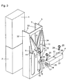
- eine Explosionsdarstellung des Spiegelmoduls und der zweiten Aufnahmevorrichtung aus
Fig. 1 , und - Fig. 4
- eine Explosionsdarstellung des Spiegelmoduls und der zweiten Aufnahmevorrichtung aus
Fig. 1 von unten. - Die
Figuren 1 bis 4 zeigen ein erfindungsgemäßes Spiegelmodul zur Befestigung an einem (in den Figuren nicht dargestellten) Strukturelement eines Raumfahrzeugs. Das Spiegelmodul umfasst eine Spiegelanordnung mit zwei Spiegelstapeln 1, 2. Jeder der Spiegelstapel 1, 2, welche auch als Spiegel-Stacks bezeichnet werden, umfasst z.B. jeweils 45 Einzelspiegel mit einer Porenoptik. Jeder Einzelspiegel und damit der Spiegelstapel 1, 2 sind aus Silizium gefertigt. Die zwei in einem definierten Winkel zueinander orientierten Spiegelstapel 1, 2 sind an einer ersten Aufnahmevorrichtung 3 befestigt. Wie insbesondere aus der Draufsicht ausFig. 2 gut hervorgeht, ist die erste Aufnahmevorrichtung 3 im Querschnitt U-förmig ausgebildet, wobei die Spiegelstapel 1, 2 jeweils an Schenkeln 32, 33 sowie an einem die Schenkel verbindenden Flächenabschnitt 34 anliegen. Eine Verbindung der Spiegelstapel 1, 2 mit der ersten Aufnahmevorrichtung 3 erfolgt im Bereich der Schenkel 32, 33 unter Verwendung eines Klebers. Die erste Aufnahmevorrichtung ist ebenfalls aus Silizium gefertigt, um einen zu dem Material der Spiegelstapel 1, 2 angepassten Wärmeausdehnungskoeffizienten bereitzustellen, so dass eine identische Längenausdehnung dieser beiden Bauteile für alle Temperaturlastfälle gewährleistet ist. Die erste Aufnahmevorrichtung 3 ist aus dem Silizium integralgefräst. - Wie aus den perspektivischen Darstellungen der
Figuren 1 ,3 und4 gut zu erkennen ist, umfasst die erste Aufnahmevorrichtung 3 an dem Flächenabschnitt 34 auf der rückwärtigen Seite eine zentral angeordnete Befestigungsvorrichtung 6 (zentrale Befestigungsvorrichtung), von welcher sich ein Befestigungssteg 7 erstreckt. Quer zu dem Befestigungssteg 7 erstreckt sich eine Anlagefläche 8. An den jeweils äußeren Rändern des Flächenabschnitts 34 sind Abstützungen 9, 10 angeordnet, welche jeweils eine Abstützfläche 11, 12 aufweisen, welche in einer Ebene mit der Anlagefläche 8 liegen. Die Abstützungen 9, 10 sind zumindest teilweise durch einen Schlitz von dem Flächenabschnitt 34 der ersten Aufnahmevorrichtung 3 beabstandet, so dass diese eine gewisse Flexibilität quer zur Ebene des Flächenabschnitts 34 aufweisen. - Die erste Aufnahmevorrichtung 3 mit den daran angeordneten Spiegelstapeln 1, 2 wird an der zentralen Befestigungsvorrichtung, insbesondere dem Befestigungssteg 7, mit einer entsprechend ausgestalteten zweiten Aufnahmevorrichtung 4 verbunden. Die zweite Aufnahmevorrichtung 4 wird aus Invar, einer Eisen-NickelLegierung, gebildet, welche die Eigenschaft besitzt, sehr kleine oder zum Teil negative Wärmeausdehnungskoeffizienten zu haben.
- Die zweite Aufnahmevorrichtung 4 ist hufeisenförmig ausgebildet (vgl. Draufsicht in
Fig. 2 ), wobei die Abmaße der äußeren Aufnahmevorrichtung 4 an die Abmaße der U-förmigen ersten Aufnahmevorrichtung 3 angepasst sind. Ein Schenkel 35, 36 verbindender Steg 37 ist im Querschnitt als geschlossenes Vierkantprofil ausgebildet, wodurch die zweite Aufnahmevorrichtung torsions- und biegesteif ist. Im Bereich des Befestigungsstegs 7 der zentralen Befestigungsvorrichtung der ersten Aufnahmevorrichtung 3 weist der Steg 37 der zweiten Aufnahmevorrichtung 4 eine Nut 13 auf, in welche der Befestigungssteg 7 ragt, so dass nach dem Zusammenfügen von erster und zweiter Aufnahmevorrichtung 3, 4 der Steg 37 an dem Flächenabschnitt 34 zur Anlage gelangt. Eine mechanische Verbindung von erster und zweiter Aufnahmevorrichtung 3, 4 erfolgt zwischen dem Befestigungssteg 7 und der korrespondierenden Nut 13 sowie den Abstützflächen 11, 12 und dem Steg 37. Optional kann auch eine Verbindung zwischen der Anlagefläche 8 und der Oberseite des Stegs 37 hergestellt sein. Die Verbindung erfolgt durch Verklebung. - Die Anlagefläche 8 weist eine Breite von ca. 1,5 cm auf und dient als Anlage- und gegebenenfalls Klebefläche zu der zweiten Aufnahmevorrichtung 4, d.h. dessen Steg 37. Durch die zentrale Verbindung der ersten Aufnahmevorrichtung 3 mit der zweiten Aufnahmevorrichtung 4 mit einer vorzugsweise maximalen Klebelänge von ca. 2 cm ist die Gefahr von zu hohen Schubspannungen, welche durch unterschiedliche Längenausdehnungskoeffizienten zwischen Silizium und Invar bedingt sind, selbst bei hohen Temperaturschwankungen minimiert.
- Die Abstützungen 9, 10 dienen zum Auffangen von Kippmomenten, wobei deren Abstützflächen 11, 12 ebenfalls mit dem Steg 37 der zweiten Aufnahmevorrichtung 34 verklebt sind. Einer unterschiedlichen Längenausdehnung in Querrichtung wird durch entsprechende Biegeweichheit der seitlich geschlitzten Abstützungen 9, 10 Rechnung getragen.
- Die Schenkel 35, 36 der zweiten Aufnahmevorrichtung 4 sind nicht mit den Schenkeln 32, 33 der ersten Aufnahmevorrichtung 3 verbunden. Vielmehr ist zwischen jeweiligen Schenkeln 32, 35 bzw. 33, 36 ein Spalt 30 bzw. 31 gebildet.
- Eine Lastanbindung der ersten Aufnahmevorrichtung mit der zweiten Aufnahmevorrichtung 4 zu der zentralen Befestigungsvorrichtung 6, welche den zentralen Anbindepunkt darstellt, erfolgt lediglich über das geschlossene Vierkantprofil, d.h. den Steg 37, der zweiten Aufnahmevorrichtung 4. Die Anbindung erfolgt hierbei auf der Rückseite der Spiegelstapel 1, 2.
- Die vorgeschlagene Befestigung des Spiegelmoduls an einem Strukturelement eines Raumfahrzeugs stellt eine isostatische, thermostabile Aufhängung mit Zentrum in der Mitte der zweiten Aufnahmevorrichtung 4 dar. Lasten von außen werden dadurch zuverlässig von den Spiegelstapeln 1, 2 entkoppelt.
- Die Anbindung eines derart vorbereiteten Spiegelmoduls erfolgt über an den Schenkeln 35, 36 ausgebildete Befestigungsflansche 14, 15, 16. In jedem der Befestigungflansche 14, 15, 16 ist eine Bohrung 17 bzw. 18 bzw. 19 vorgesehen, so dass die zweite Aufnahmevorrichtung 4 mittels Befestigungsschrauben 23, 24, 25 an dem in den Figuren nicht dargestellten Strukturelement befestigt werden kann. Das Vorsehen zweier Befestigungsflansche 14, 15 an dem Schenkel 35 und eines Befestigungsflansches 16 an dem Schenkel 36 stellt eine sog. 3-Punkt-Lagerung dar.
- Vor der endgültigen Befestigung der Spiegelstapel 1, 2 können diese lateral über die Bohrungen 17, 18, 19 und bezüglich ihrer Winkelausrichtung über Kugeldruck-Feingewindeschrauben ausgerichtet werden. Hierzu sind in den Befestigungsflanschen 14, 15, 16 Feingewindebohrungen 20, 21, 22 vorgesehen, in welche die Kugeldruckschrauben 26, 27, 28 zur Ausrichtung eingedreht werden können.
- Bei dem beschriebenen Spiegelmodul ist eine vollständige Entkopplung der Spiegel-Aufhängung, d.h. der ersten Befestigungsvorrichtung 3, zu dem Strukturelement, wie z.B. CFK, durch das isostatische Zwischenschalten der zweiten Aufnahmevorrichtung aus Invar sichergestellt. Dies gilt sowohl gegenüber thermischen wie auch von außen einwirkenden, mechanischen Lasten. Die Verwendung von identischem Material für die Spiegelstapel 1, 2 und erster Aufnahmevorrichtung 3 sowie Invar als Material für die isostatische Aufhängung vermittels der zweiten Aufnahmevorrichtung 4 gewährleistet eine zuverlässige Kalibration der Optik bei Raumtemperaturumgebung und gleichfalls definierte Bedingungen an deren späterem Einsatzort bei z.B. 60 K. Hierdurch wird eine vollständige Unabhängigkeit der Leistungsfähigkeit der Spiegeistapel 1, 2 für alle auftretenden Temperaturfälle erreicht. Die Verwendung einer zweiten Aufnahmevorrichtung 4 aus Invar als isostatische Aufhängung erlaubt eine risikofreie Befestigung der Spiegelstapel 1, 2 und stellt eine hervorragende Isolierung der Spiegelstapel gegenüber äußeren Kräften dar.
-
- 1
- Spiegelstapel
- 2
- Spiegelstapel
- 3
- erste Aufnahmevorrichtung
- 4
- zweite Aufnahmevorrichtung
- 5
- Seitenwand der ersten Aufnahmevorrichtung
- 6
- zentrale Befestigungsvorrichtung
- 7
- Befestigungssteg
- 8
- Anlagefläche
- 9
- Abstützung
- 10
- Abstützung
- 11
- Abstützfläche
- 12
- Abstützfläche
- 13
- Nut
- 14
- Befestigungsflansch
- 15
- Befestigungsflansch
- 16
- Befestigungsflansch
- 17
- Bohrung
- 18
- Bohrung
- 19
- Bohrung
- 20
- Feingewindebohrung
- 21
- Feingewindebohrung
- 22
- Feingewindebohrung
- 23
- Befestigungsschraube
- 24
- Befestigungsschraube
- 25
- Befestigungsschraube
- 26
- Kugeldruckschraube
- 27
- Kugeldruckschraube
- 28
- Kugeldruckschraube
- 29
- Anlagefläche
- 30
- Spalt
- 31
- Spalt
- 32
- Schenkel
- 33
- Schenkel
- 34
- Flächenabschnitt
- 35
- Schenkel
- 36
- Schenkel
- 37
- Steg
Claims (16)
- Spiegelmodul zur Befestigung an einem Strukturelement mit einer Spiegelanordnung, welche zumindest einen Spiegelstapel (1, 2) aufweist, wobei der zumindest eine Spiegelstapel (1, 2) jeweils zumindest einen Einzelspiegel aus einem ersten Material umfasst, und mit einer ersten Aufnahmevorrichtung (3) zur Halterung der Spiegelanordnung, wobei die erste Aufnahmevorrichtung (3) aus einem zweiten Material gebildet ist, das einen zu dem ersten Material angepassten Wärmeausdehnungskoeffizienten aufweist, und wobei zur Befestigung des Spiegelmoduls an dem Strukturelement eine zweite Aufnahmevorrichtung (4) aus Invar vorgesehen ist, welche die erste Aufnahmevorrichtung (3) des Spiegelmoduls haltert.
- Spiegelmodul nach Anspruch 1, bei dem das erste Material der Spiegelanordnung und das zweite Material der ersten Aufnahmevorrichtung (3) Silizium sind.
- Spiegelmodul nach Anspruch 1 oder 2, bei dem die Spiegelanordnung mit der ersten Aufnahmevorrichtung (3) verklebt ist.
- Spiegelmodul nach einem der vorherigen Ansprüche, bei dem die erste Aufnahmevorrichtung (3) U-förmig ausgebildet ist, wobei die Spiegelanordnung an Schenkeln (32, 33) der ersten Aufnahmevorrichtung (3) und einem die Schenkel (32, 33) verbindenden Flächenabschnitt (34) anliegt.
- Spiegelmodul nach Anspruch 3 und 4, bei dem die Verklebung der Spiegelanordnung mit der ersten Aufnahmevorrichtung (3) nur im Bereich der Schenkel (32, 33) erfolgt.
- Spiegelmodul nach einem der vorherigen Ansprüche, bei dem die zweite Aufnahmevorrichtung (4) mit einer zentral angeordneten Befestigungsvorrichtung (6) der ersten Aufnahmevorrichtung (3) verbunden ist.
- Spiegelmodul nach einem der vorherigen Ansprüche, bei dem die Verbindung der zweiten Aufnahmevorrichtung (4) mit der ersten Aufnahmevorrichtung (3), insbesondere ausschließlich, auf der Rückseite der Spiegelanordnung erfolgt.
- Spiegelmodul nach Anspruch 6 oder 7, bei dem die zentrale Befestigungsvorrichtung (6) einen Befestigungssteg (7) umfasst, der in eine Nut (13) der zweiten Aufnahmevorrichtung (4) ragt, wenn die erste und die zweite Aufnahmevorrichtung (3, 4) miteinander verbunden sind, wobei die erste und die zweite Aufnahmevorrichtung (3, 4) im Bereich dieser Elemente verbunden sind.
- Spiegelmodul nach Anspruch 8, bei dem die zentrale Befestigungsvorrichtung (6) eine Anlagefläche (8) umfasst, welche sich quer zu dem Befestigungssteg (7) erstreckt, mit welchem die zweite Aufnahmevorrichtung (4) verbunden ist.
- Spiegelmodul nach einem der vorherigen Ansprüche, bei dem die erste Aufnahmevorrichtung (3) an dem Flächenabschnitt Abstützungen (9, 10) aufweist, welche an jeweiligen Abstützflächen (11, 12) mit der zweiten Aufnahmevorrichtung (4) verbunden sind.
- Spiegelmodul nach einem der vorherigen Ansprüche, bei dem die erste und die zweite Aufnahmevorrichtung (3, 4) miteinander verklebt sind.
- Spiegelmodul nach einem der vorherigen Ansprüche, bei dem die zweite Aufnahmevorrichtung (4) hufeisenförmig ausgebildet ist und an dem Flächenabschnitt (34) der ersten Aufnahmevorrichtung (3) anliegt, und optional zumindest abschnittsweise mit diesem verbunden ist.
- Spiegelmodul nach einem der Ansprüche 4 bis 12, bei dem zwischen der ersten und der zweiten Aufnahmevorrichtung (3, 4) im Bereich der Schenkel (32, 33; 35, 36) der ersten Aufnahmevorrichtung (3) ein Spalt (30, 31) gebildet ist.
- Spiegelmodul nach einem der vorherigen Ansprüche, bei dem die zweite Aufnahmevorrichtung (4) im Querschnitt als geschlossenes Vierkantprofil ausgebildet ist.
- Spiegelmodul nach einem der vorherigen Ansprüche, bei dem die Spiegelanordnung zwei in einem definierten Winkel zueinander orientierte Spiegelstapel (1, 2) umfasst.
- Spiegelmodul nach einem der vorherigen Ansprüche, bei dem jeder Spiegelstapel (1, 2) 45 Einzelspiegel mit Porenoptik aus Silizium umfasst.
Applications Claiming Priority (1)
| Application Number | Priority Date | Filing Date | Title |
|---|---|---|---|
| DE102008007060A DE102008007060B3 (de) | 2008-01-31 | 2008-01-31 | Spiegelmodul zur Befestigung an einem Strukturelement |
Publications (2)
| Publication Number | Publication Date |
|---|---|
| EP2085803A1 true EP2085803A1 (de) | 2009-08-05 |
| EP2085803B1 EP2085803B1 (de) | 2011-07-20 |
Family
ID=40592080
Family Applications (1)
| Application Number | Title | Priority Date | Filing Date |
|---|---|---|---|
| EP09000745A Not-in-force EP2085803B1 (de) | 2008-01-31 | 2009-01-21 | Temperatur-unempfindliches Spiegelmodul zur Befestigung an einem Strukturelement |
Country Status (5)
| Country | Link |
|---|---|
| US (2) | US20090195899A1 (de) |
| EP (1) | EP2085803B1 (de) |
| AT (1) | ATE517362T1 (de) |
| DE (1) | DE102008007060B3 (de) |
| ES (1) | ES2368977T3 (de) |
Cited By (1)
| Publication number | Priority date | Publication date | Assignee | Title |
|---|---|---|---|---|
| EP2871507A1 (de) * | 2013-11-06 | 2015-05-13 | Airbus DS GmbH | Strahllenkspiegelvorrichtung |
Citations (4)
| Publication number | Priority date | Publication date | Assignee | Title |
|---|---|---|---|---|
| US5162951A (en) * | 1990-07-31 | 1992-11-10 | Eastman Kodak Company | Method for designing an optical system |
| JPH0868898A (ja) * | 1994-08-29 | 1996-03-12 | Nikon Corp | 反射鏡およびその製造方法 |
| US5801891A (en) * | 1997-04-14 | 1998-09-01 | Eastman Kodak Company | Flat mirror mounting flexure |
| JP2004191556A (ja) * | 2002-12-10 | 2004-07-08 | Nikon Corp | 支持装置、ステージ装置及び露光装置 |
Family Cites Families (30)
| Publication number | Priority date | Publication date | Assignee | Title |
|---|---|---|---|---|
| US3121605A (en) * | 1958-09-22 | 1964-02-18 | Nunn Joseph | Tracking and photographic apparatus |
| US3484715A (en) * | 1966-04-21 | 1969-12-16 | Spectra Physics | Temperature compensating mounting for laser reflectors |
| US3588737A (en) * | 1968-04-22 | 1971-06-28 | Electro Nuclear Lab Inc | Thermally stabilized laser |
| US3532408A (en) * | 1968-05-20 | 1970-10-06 | Bulova Watch Co Inc | Resonant torsional oscillators |
| US3574462A (en) * | 1968-09-26 | 1971-04-13 | Nasa | Maksutov spectrograph |
| US3574448A (en) * | 1969-05-13 | 1971-04-13 | Nasa | Adjustable mount for a trihedral mirror |
| US3793595A (en) * | 1971-12-27 | 1974-02-19 | Perkin Elmer Corp | Single frequency stabilized laser |
| DE2414266A1 (de) * | 1974-03-25 | 1975-10-09 | Zeiss Carl Fa | Vorrichtung zur radialen zug-druck- entlastung grosser teleskopspiegel |
| US4044283A (en) * | 1975-10-22 | 1977-08-23 | Schiller Industries, Inc. | Electromechanical resonator |
| DE3018785C2 (de) * | 1980-05-16 | 1982-04-15 | Heraeus Quarzschmelze Gmbh, 6450 Hanau | Leichtgewichtsspiegel, insbesondere für astronomische Zwecke und Verfahren zu seiner Herstellung |
| FR2563017B1 (fr) * | 1984-04-17 | 1987-11-20 | Trt Telecom Radio Electr | Collimateur d'harmonisation entre deux dispositifs optiques |
| US4691323A (en) * | 1984-06-11 | 1987-09-01 | The Singer Company | Path length controller for ring laser gyroscope |
| DD279385A3 (de) * | 1985-02-04 | 1990-06-06 | Zeiss Jena Veb Carl | Spiegelhalterung |
| US4726671A (en) * | 1986-06-19 | 1988-02-23 | The Perkin-Elmer Corporation | High resonance adjustable mirror mount |
| DE3634196A1 (de) * | 1986-10-08 | 1988-04-21 | Zeiss Carl Fa | Einrichtung zur verbindung zweier koerper mit unterschiedlichen thermischen ausdehnungskoeffizienten |
| FR2637379B1 (fr) * | 1988-09-30 | 1990-12-21 | Aerospatiale | Dispositif de fixation d'un organe optique tel qu'un filtre sur un support |
| US4940318A (en) * | 1988-11-03 | 1990-07-10 | Itek Corporation | Gradient membrane deformable mirror having replaceable actuators |
| US4906087A (en) * | 1989-06-16 | 1990-03-06 | Litton Systems, Inc. | Magneto-retractive deformable mirror |
| US4934803A (en) * | 1989-10-12 | 1990-06-19 | Litton Systems, Inc. | Differential pressure deformable mirror |
| IL93738A (en) * | 1990-03-14 | 1994-10-07 | Israel State | Single axis optical system made from a single portion of material |
| US5037190A (en) * | 1990-07-27 | 1991-08-06 | Litton Systems, Inc. | Fusible link actuators for deformable mirrors |
| US5058993A (en) * | 1990-10-01 | 1991-10-22 | Hughes Aircraft Company | Lightweight optical bench and method of fabricating same |
| JPH05288908A (ja) * | 1992-04-09 | 1993-11-05 | Toshiba Corp | 光学系 |
| JP3058000B2 (ja) * | 1994-02-28 | 2000-07-04 | キヤノン株式会社 | ミラー光学装置 |
| US6048070A (en) * | 1996-02-28 | 2000-04-11 | Raytheon Company | Durable large stroke deformable mirror |
| FR2764081B1 (fr) * | 1997-06-03 | 1999-08-20 | Reosc | Systeme catoptrique grand angulaire a miroirs |
| JP2003241049A (ja) * | 2002-02-22 | 2003-08-27 | Nikon Corp | 光学素子保持方法、光学素子研磨加工方法及び光学素子成膜方法 |
| DE10302664A1 (de) * | 2003-01-24 | 2004-07-29 | Carl Zeiss Smt Ag | Verfahren zur Herstellung eines Facettenspiegels |
| US7172299B2 (en) * | 2004-09-08 | 2007-02-06 | Xinetics, Inc. | Integrated wavefront correction module with reduced translation |
| US8092030B2 (en) * | 2006-04-12 | 2012-01-10 | Plx, Inc. | Mount for an optical structure and method of mounting an optical structure using such mount |
-
2008
- 2008-01-31 DE DE102008007060A patent/DE102008007060B3/de not_active Expired - Fee Related
-
2009
- 2009-01-21 AT AT09000745T patent/ATE517362T1/de active
- 2009-01-21 ES ES09000745T patent/ES2368977T3/es active Active
- 2009-01-21 EP EP09000745A patent/EP2085803B1/de not_active Not-in-force
- 2009-01-30 US US12/363,026 patent/US20090195899A1/en not_active Abandoned
-
2011
- 2011-03-03 US US13/039,910 patent/US20110157731A1/en not_active Abandoned
Patent Citations (4)
| Publication number | Priority date | Publication date | Assignee | Title |
|---|---|---|---|---|
| US5162951A (en) * | 1990-07-31 | 1992-11-10 | Eastman Kodak Company | Method for designing an optical system |
| JPH0868898A (ja) * | 1994-08-29 | 1996-03-12 | Nikon Corp | 反射鏡およびその製造方法 |
| US5801891A (en) * | 1997-04-14 | 1998-09-01 | Eastman Kodak Company | Flat mirror mounting flexure |
| JP2004191556A (ja) * | 2002-12-10 | 2004-07-08 | Nikon Corp | 支持装置、ステージ装置及び露光装置 |
Cited By (2)
| Publication number | Priority date | Publication date | Assignee | Title |
|---|---|---|---|---|
| EP2871507A1 (de) * | 2013-11-06 | 2015-05-13 | Airbus DS GmbH | Strahllenkspiegelvorrichtung |
| US9500854B2 (en) | 2013-11-06 | 2016-11-22 | Airbus Ds Gmbh | Beam steering mirror device |
Also Published As
| Publication number | Publication date |
|---|---|
| US20090195899A1 (en) | 2009-08-06 |
| US20110157731A1 (en) | 2011-06-30 |
| ES2368977T3 (es) | 2011-11-24 |
| DE102008007060B3 (de) | 2009-08-06 |
| ATE517362T1 (de) | 2011-08-15 |
| EP2085803B1 (de) | 2011-07-20 |
Similar Documents
| Publication | Publication Date | Title |
|---|---|---|
| EP3026389B1 (de) | Längenmesseinrichtung | |
| WO2001003282A9 (de) | Piezoelektrischer antrieb, insbesondere halterahmen, friktionselement und schaltungsanordnung | |
| DE102018106012B3 (de) | Justierbare Spiegelbaugruppe mit Blattfederelement | |
| WO2000079611A1 (de) | Piezoaktor mit temperaturkompensation | |
| DE102010017140A1 (de) | Vorrichtung zur Positionierung einer Spanneinheit zum positionsgenauen Aufspannen von Werkstücken sowie Aufspannsystem | |
| EP2361443A1 (de) | Elektromechanischer energiewandler zur erzeugung von elektrischer energie aus mechanischen bewegungen | |
| DE102014109681B4 (de) | Faltungsoptik für einen Laserpulskompressor sowie Laserpulsanordnung mit einer Faltungsoptik | |
| EP2085803B1 (de) | Temperatur-unempfindliches Spiegelmodul zur Befestigung an einem Strukturelement | |
| DE60218600T2 (de) | Hochleistungsfassung für optische Elemente unter Wärme- und Schwingungsbeanspruchung | |
| EP0561190A1 (de) | Formeinstellbarer Teleskopspiegel | |
| EP0565069A1 (de) | Verstellbare Blende und Verfahren zu ihrer Herstellung | |
| EP0922981A2 (de) | Verbundener Körper | |
| EP1721056B1 (de) | Klebekonstruktion | |
| EP1894258B1 (de) | Positionierer mit festkörpergelenk | |
| DE102009042985A1 (de) | Anordnung zum Verbinden eines Karosserieteils mit einer Karosseriestruktur eines Fahrzeugs | |
| EP0926525B1 (de) | Positioniertisch | |
| DE102018124483B3 (de) | Optikbaugruppe mit einem Optikelement mit einer planen Montagefläche großer Ausdehnung | |
| DE3711466A1 (de) | Vorrichtung zur verbindung von koerpern | |
| EP1938134A2 (de) | Optischer aufbau mit elastischer aufhängung und verfahren zur herstellung eines solchen | |
| WO2021259858A1 (de) | Verbindung von komponenten einer optischen abbildungseinrichtung | |
| DE10217164B4 (de) | Piezoelektrische Vorrichtung | |
| DE19828526C1 (de) | Montagehilfsvorrichtung zur Justierung und Fixierung zweier aneinanderstoßender Platten | |
| WO2005022231A1 (de) | Vorrichtung zur verhinderung des kriechens eines optischen elementes | |
| DE102011084463A1 (de) | Vorrichtung zum Ausrichten von Teilen eines Türrahmens | |
| DE60305953T2 (de) | Vorrichtung zur zweidimensionalen verschiebung |
Legal Events
| Date | Code | Title | Description |
|---|---|---|---|
| PUAI | Public reference made under article 153(3) epc to a published international application that has entered the european phase |
Free format text: ORIGINAL CODE: 0009012 |
|
| AK | Designated contracting states |
Kind code of ref document: A1 Designated state(s): AT BE BG CH CY CZ DE DK EE ES FI FR GB GR HR HU IE IS IT LI LT LU LV MC MK MT NL NO PL PT RO SE SI SK TR |
|
| AX | Request for extension of the european patent |
Extension state: AL BA RS |
|
| 17P | Request for examination filed |
Effective date: 20100119 |
|
| 17Q | First examination report despatched |
Effective date: 20100216 |
|
| AKX | Designation fees paid |
Designated state(s): AT BE BG CH CY CZ DE DK EE ES FI FR GB GR HR HU IE IS IT LI LT LU LV MC MK MT NL NO PL PT RO SE SI SK TR |
|
| GRAP | Despatch of communication of intention to grant a patent |
Free format text: ORIGINAL CODE: EPIDOSNIGR1 |
|
| GRAS | Grant fee paid |
Free format text: ORIGINAL CODE: EPIDOSNIGR3 |
|
| GRAA | (expected) grant |
Free format text: ORIGINAL CODE: 0009210 |
|
| AK | Designated contracting states |
Kind code of ref document: B1 Designated state(s): AT BE BG CH CY CZ DE DK EE ES FI FR GB GR HR HU IE IS IT LI LT LU LV MC MK MT NL NO PL PT RO SE SI SK TR |
|
| REG | Reference to a national code |
Ref country code: GB Ref legal event code: FG4D Free format text: NOT ENGLISH |
|
| REG | Reference to a national code |
Ref country code: CH Ref legal event code: EP |
|
| REG | Reference to a national code |
Ref country code: DE Ref legal event code: R096 Ref document number: 502009000957 Country of ref document: DE Effective date: 20110915 |
|
| REG | Reference to a national code |
Ref country code: NL Ref legal event code: T3 |
|
| REG | Reference to a national code |
Ref country code: ES Ref legal event code: FG2A Ref document number: 2368977 Country of ref document: ES Kind code of ref document: T3 Effective date: 20111124 |
|
| PG25 | Lapsed in a contracting state [announced via postgrant information from national office to epo] |
Ref country code: LT Free format text: LAPSE BECAUSE OF FAILURE TO SUBMIT A TRANSLATION OF THE DESCRIPTION OR TO PAY THE FEE WITHIN THE PRESCRIBED TIME-LIMIT Effective date: 20110720 Ref country code: SE Free format text: LAPSE BECAUSE OF FAILURE TO SUBMIT A TRANSLATION OF THE DESCRIPTION OR TO PAY THE FEE WITHIN THE PRESCRIBED TIME-LIMIT Effective date: 20110720 Ref country code: IS Free format text: LAPSE BECAUSE OF FAILURE TO SUBMIT A TRANSLATION OF THE DESCRIPTION OR TO PAY THE FEE WITHIN THE PRESCRIBED TIME-LIMIT Effective date: 20111120 Ref country code: FI Free format text: LAPSE BECAUSE OF FAILURE TO SUBMIT A TRANSLATION OF THE DESCRIPTION OR TO PAY THE FEE WITHIN THE PRESCRIBED TIME-LIMIT Effective date: 20110720 Ref country code: PT Free format text: LAPSE BECAUSE OF FAILURE TO SUBMIT A TRANSLATION OF THE DESCRIPTION OR TO PAY THE FEE WITHIN THE PRESCRIBED TIME-LIMIT Effective date: 20111121 Ref country code: NO Free format text: LAPSE BECAUSE OF FAILURE TO SUBMIT A TRANSLATION OF THE DESCRIPTION OR TO PAY THE FEE WITHIN THE PRESCRIBED TIME-LIMIT Effective date: 20111020 Ref country code: HR Free format text: LAPSE BECAUSE OF FAILURE TO SUBMIT A TRANSLATION OF THE DESCRIPTION OR TO PAY THE FEE WITHIN THE PRESCRIBED TIME-LIMIT Effective date: 20110720 |
|
| REG | Reference to a national code |
Ref country code: IE Ref legal event code: FD4D |
|
| PG25 | Lapsed in a contracting state [announced via postgrant information from national office to epo] |
Ref country code: LV Free format text: LAPSE BECAUSE OF FAILURE TO SUBMIT A TRANSLATION OF THE DESCRIPTION OR TO PAY THE FEE WITHIN THE PRESCRIBED TIME-LIMIT Effective date: 20110720 Ref country code: CY Free format text: LAPSE BECAUSE OF FAILURE TO SUBMIT A TRANSLATION OF THE DESCRIPTION OR TO PAY THE FEE WITHIN THE PRESCRIBED TIME-LIMIT Effective date: 20110720 Ref country code: SI Free format text: LAPSE BECAUSE OF FAILURE TO SUBMIT A TRANSLATION OF THE DESCRIPTION OR TO PAY THE FEE WITHIN THE PRESCRIBED TIME-LIMIT Effective date: 20110720 Ref country code: PL Free format text: LAPSE BECAUSE OF FAILURE TO SUBMIT A TRANSLATION OF THE DESCRIPTION OR TO PAY THE FEE WITHIN THE PRESCRIBED TIME-LIMIT Effective date: 20110720 Ref country code: GR Free format text: LAPSE BECAUSE OF FAILURE TO SUBMIT A TRANSLATION OF THE DESCRIPTION OR TO PAY THE FEE WITHIN THE PRESCRIBED TIME-LIMIT Effective date: 20111021 |
|
| PG25 | Lapsed in a contracting state [announced via postgrant information from national office to epo] |
Ref country code: CZ Free format text: LAPSE BECAUSE OF FAILURE TO SUBMIT A TRANSLATION OF THE DESCRIPTION OR TO PAY THE FEE WITHIN THE PRESCRIBED TIME-LIMIT Effective date: 20110720 Ref country code: SK Free format text: LAPSE BECAUSE OF FAILURE TO SUBMIT A TRANSLATION OF THE DESCRIPTION OR TO PAY THE FEE WITHIN THE PRESCRIBED TIME-LIMIT Effective date: 20110720 Ref country code: IE Free format text: LAPSE BECAUSE OF FAILURE TO SUBMIT A TRANSLATION OF THE DESCRIPTION OR TO PAY THE FEE WITHIN THE PRESCRIBED TIME-LIMIT Effective date: 20110720 |
|
| PLBE | No opposition filed within time limit |
Free format text: ORIGINAL CODE: 0009261 |
|
| STAA | Information on the status of an ep patent application or granted ep patent |
Free format text: STATUS: NO OPPOSITION FILED WITHIN TIME LIMIT |
|
| PG25 | Lapsed in a contracting state [announced via postgrant information from national office to epo] |
Ref country code: EE Free format text: LAPSE BECAUSE OF FAILURE TO SUBMIT A TRANSLATION OF THE DESCRIPTION OR TO PAY THE FEE WITHIN THE PRESCRIBED TIME-LIMIT Effective date: 20110720 Ref country code: RO Free format text: LAPSE BECAUSE OF FAILURE TO SUBMIT A TRANSLATION OF THE DESCRIPTION OR TO PAY THE FEE WITHIN THE PRESCRIBED TIME-LIMIT Effective date: 20110720 |
|
| 26N | No opposition filed |
Effective date: 20120423 |
|
| PG25 | Lapsed in a contracting state [announced via postgrant information from national office to epo] |
Ref country code: DK Free format text: LAPSE BECAUSE OF FAILURE TO SUBMIT A TRANSLATION OF THE DESCRIPTION OR TO PAY THE FEE WITHIN THE PRESCRIBED TIME-LIMIT Effective date: 20110720 |
|
| PGFP | Annual fee paid to national office [announced via postgrant information from national office to epo] |
Ref country code: IT Payment date: 20120131 Year of fee payment: 4 |
|
| BERE | Be: lapsed |
Owner name: ASTRIUM G.M.B.H. Effective date: 20120131 |
|
| REG | Reference to a national code |
Ref country code: DE Ref legal event code: R097 Ref document number: 502009000957 Country of ref document: DE Effective date: 20120423 |
|
| PG25 | Lapsed in a contracting state [announced via postgrant information from national office to epo] |
Ref country code: MC Free format text: LAPSE BECAUSE OF NON-PAYMENT OF DUE FEES Effective date: 20120131 |
|
| PG25 | Lapsed in a contracting state [announced via postgrant information from national office to epo] |
Ref country code: BE Free format text: LAPSE BECAUSE OF NON-PAYMENT OF DUE FEES Effective date: 20120131 |
|
| PG25 | Lapsed in a contracting state [announced via postgrant information from national office to epo] |
Ref country code: MK Free format text: LAPSE BECAUSE OF FAILURE TO SUBMIT A TRANSLATION OF THE DESCRIPTION OR TO PAY THE FEE WITHIN THE PRESCRIBED TIME-LIMIT Effective date: 20110720 |
|
| PGFP | Annual fee paid to national office [announced via postgrant information from national office to epo] |
Ref country code: ES Payment date: 20130128 Year of fee payment: 5 Ref country code: GB Payment date: 20130122 Year of fee payment: 5 Ref country code: DE Payment date: 20130122 Year of fee payment: 5 Ref country code: FR Payment date: 20130213 Year of fee payment: 5 |
|
| PGFP | Annual fee paid to national office [announced via postgrant information from national office to epo] |
Ref country code: NL Payment date: 20130122 Year of fee payment: 5 |
|
| PG25 | Lapsed in a contracting state [announced via postgrant information from national office to epo] |
Ref country code: BG Free format text: LAPSE BECAUSE OF FAILURE TO SUBMIT A TRANSLATION OF THE DESCRIPTION OR TO PAY THE FEE WITHIN THE PRESCRIBED TIME-LIMIT Effective date: 20111020 |
|
| PG25 | Lapsed in a contracting state [announced via postgrant information from national office to epo] |
Ref country code: MT Free format text: LAPSE BECAUSE OF FAILURE TO SUBMIT A TRANSLATION OF THE DESCRIPTION OR TO PAY THE FEE WITHIN THE PRESCRIBED TIME-LIMIT Effective date: 20110720 |
|
| REG | Reference to a national code |
Ref country code: CH Ref legal event code: PL |
|
| PG25 | Lapsed in a contracting state [announced via postgrant information from national office to epo] |
Ref country code: LI Free format text: LAPSE BECAUSE OF NON-PAYMENT OF DUE FEES Effective date: 20130131 Ref country code: CH Free format text: LAPSE BECAUSE OF NON-PAYMENT OF DUE FEES Effective date: 20130131 |
|
| PG25 | Lapsed in a contracting state [announced via postgrant information from national office to epo] |
Ref country code: TR Free format text: LAPSE BECAUSE OF FAILURE TO SUBMIT A TRANSLATION OF THE DESCRIPTION OR TO PAY THE FEE WITHIN THE PRESCRIBED TIME-LIMIT Effective date: 20110720 |
|
| PG25 | Lapsed in a contracting state [announced via postgrant information from national office to epo] |
Ref country code: LU Free format text: LAPSE BECAUSE OF NON-PAYMENT OF DUE FEES Effective date: 20120121 |
|
| PG25 | Lapsed in a contracting state [announced via postgrant information from national office to epo] |
Ref country code: HU Free format text: LAPSE BECAUSE OF FAILURE TO SUBMIT A TRANSLATION OF THE DESCRIPTION OR TO PAY THE FEE WITHIN THE PRESCRIBED TIME-LIMIT Effective date: 20090121 |
|
| REG | Reference to a national code |
Ref country code: DE Ref legal event code: R119 Ref document number: 502009000957 Country of ref document: DE |
|
| REG | Reference to a national code |
Ref country code: NL Ref legal event code: V1 Effective date: 20140801 |
|
| GBPC | Gb: european patent ceased through non-payment of renewal fee |
Effective date: 20140121 |
|
| REG | Reference to a national code |
Ref country code: DE Ref legal event code: R119 Ref document number: 502009000957 Country of ref document: DE Effective date: 20140801 |
|
| PG25 | Lapsed in a contracting state [announced via postgrant information from national office to epo] |
Ref country code: NL Free format text: LAPSE BECAUSE OF NON-PAYMENT OF DUE FEES Effective date: 20140801 Ref country code: DE Free format text: LAPSE BECAUSE OF NON-PAYMENT OF DUE FEES Effective date: 20140801 |
|
| REG | Reference to a national code |
Ref country code: FR Ref legal event code: ST Effective date: 20140930 |
|
| PG25 | Lapsed in a contracting state [announced via postgrant information from national office to epo] |
Ref country code: FR Free format text: LAPSE BECAUSE OF NON-PAYMENT OF DUE FEES Effective date: 20140131 Ref country code: GB Free format text: LAPSE BECAUSE OF NON-PAYMENT OF DUE FEES Effective date: 20140121 |
|
| REG | Reference to a national code |
Ref country code: AT Ref legal event code: MM01 Ref document number: 517362 Country of ref document: AT Kind code of ref document: T Effective date: 20140121 |
|
| REG | Reference to a national code |
Ref country code: ES Ref legal event code: FD2A Effective date: 20150327 |
|
| PG25 | Lapsed in a contracting state [announced via postgrant information from national office to epo] |
Ref country code: ES Free format text: LAPSE BECAUSE OF NON-PAYMENT OF DUE FEES Effective date: 20140122 |
|
| PG25 | Lapsed in a contracting state [announced via postgrant information from national office to epo] |
Ref country code: AT Free format text: LAPSE BECAUSE OF NON-PAYMENT OF DUE FEES Effective date: 20140121 |
|
| PG25 | Lapsed in a contracting state [announced via postgrant information from national office to epo] |
Ref country code: IT Free format text: LAPSE BECAUSE OF NON-PAYMENT OF DUE FEES Effective date: 20140121 |