EP2085752B1 - Dispositif optique de mesure de la position - Google Patents
Dispositif optique de mesure de la position Download PDFInfo
- Publication number
- EP2085752B1 EP2085752B1 EP08171105.3A EP08171105A EP2085752B1 EP 2085752 B1 EP2085752 B1 EP 2085752B1 EP 08171105 A EP08171105 A EP 08171105A EP 2085752 B1 EP2085752 B1 EP 2085752B1
- Authority
- EP
- European Patent Office
- Prior art keywords
- grid
- scanning
- measuring device
- different
- position measuring
- Prior art date
- Legal status (The legal status is an assumption and is not a legal conclusion. Google has not performed a legal analysis and makes no representation as to the accuracy of the status listed.)
- Active
Links
- 230000003287 optical effect Effects 0.000 title claims description 35
- 238000001514 detection method Methods 0.000 claims description 30
- 239000000463 material Substances 0.000 claims description 28
- 230000000737 periodic effect Effects 0.000 claims description 13
- 230000001419 dependent effect Effects 0.000 claims description 12
- 230000000694 effects Effects 0.000 claims description 10
- 230000003993 interaction Effects 0.000 claims description 5
- 230000001902 propagating effect Effects 0.000 claims description 5
- 230000005855 radiation Effects 0.000 description 13
- 238000005070 sampling Methods 0.000 description 8
- 230000005484 gravity Effects 0.000 description 7
- 239000003795 chemical substances by application Substances 0.000 description 5
- 238000006073 displacement reaction Methods 0.000 description 3
- 230000010287 polarization Effects 0.000 description 3
- 239000000758 substrate Substances 0.000 description 3
- 238000011109 contamination Methods 0.000 description 2
- 238000011156 evaluation Methods 0.000 description 2
- 230000007274 generation of a signal involved in cell-cell signaling Effects 0.000 description 2
- 238000009434 installation Methods 0.000 description 2
- 238000005259 measurement Methods 0.000 description 2
- 230000035699 permeability Effects 0.000 description 2
- 230000005540 biological transmission Effects 0.000 description 1
- 238000006243 chemical reaction Methods 0.000 description 1
- 239000000356 contaminant Substances 0.000 description 1
- 230000009977 dual effect Effects 0.000 description 1
- 238000000605 extraction Methods 0.000 description 1
- 239000011521 glass Substances 0.000 description 1
- 238000005286 illumination Methods 0.000 description 1
- 238000004519 manufacturing process Methods 0.000 description 1
- 230000035945 sensitivity Effects 0.000 description 1
Images


Classifications
-
- G—PHYSICS
- G01—MEASURING; TESTING
- G01D—MEASURING NOT SPECIALLY ADAPTED FOR A SPECIFIC VARIABLE; ARRANGEMENTS FOR MEASURING TWO OR MORE VARIABLES NOT COVERED IN A SINGLE OTHER SUBCLASS; TARIFF METERING APPARATUS; MEASURING OR TESTING NOT OTHERWISE PROVIDED FOR
- G01D5/00—Mechanical means for transferring the output of a sensing member; Means for converting the output of a sensing member to another variable where the form or nature of the sensing member does not constrain the means for converting; Transducers not specially adapted for a specific variable
- G01D5/26—Mechanical means for transferring the output of a sensing member; Means for converting the output of a sensing member to another variable where the form or nature of the sensing member does not constrain the means for converting; Transducers not specially adapted for a specific variable characterised by optical transfer means, i.e. using infrared, visible, or ultraviolet light
- G01D5/32—Mechanical means for transferring the output of a sensing member; Means for converting the output of a sensing member to another variable where the form or nature of the sensing member does not constrain the means for converting; Transducers not specially adapted for a specific variable characterised by optical transfer means, i.e. using infrared, visible, or ultraviolet light with attenuation or whole or partial obturation of beams of light
- G01D5/34—Mechanical means for transferring the output of a sensing member; Means for converting the output of a sensing member to another variable where the form or nature of the sensing member does not constrain the means for converting; Transducers not specially adapted for a specific variable characterised by optical transfer means, i.e. using infrared, visible, or ultraviolet light with attenuation or whole or partial obturation of beams of light the beams of light being detected by photocells
- G01D5/36—Forming the light into pulses
- G01D5/38—Forming the light into pulses by diffraction gratings
Definitions
- the present invention relates to an optical position measuring device which is suitable for determining the relative position of two mutually movable objects.
- periodic fringe patterns are generated via the interaction of a radiation beam emitted by a light source with a material measure and optionally further gratings in the scanning beam path.
- the material measure and a scanning unit results in an intensity modulation of the fringe pattern, which can be evaluated to generate displacement-dependent incremental signals.
- Such an evaluation can be carried out, for example, via so-called structured photodetectors, which consist of a periodic arrangement of photodiodes. The periodicity of the detector arrangement is matched to the periodicity of the stripe pattern, depending on the number of phase-shifted incremental signals.
- Object of the present invention is to provide an optical position measuring device that allows reliable detection of fine stripe patterns in a scanning plane with high efficiency and the greatest possible insensitivity to contamination of the material measure.
- Each grating section has a periodic grating structure which effects a deflection of the beam propagating through this grating section in a plurality of spatial directions. The resulting spatial directions of the grating sections in a block differ.
- the detection plane lies in an area in which the radiation beams coming from the scanning grating are completely spatially separated.
- the optical position measuring device consists of generating n> 1 phase-shifted, shift-dependent incremental signals with respect to two objects movable in one measuring direction from a material measure and a scanning unit having a scanning grid arranged in a scanning plane and a plurality of detector elements arranged downstream of the scanning grid. wherein a fringe pattern with the fringe pattern periodicity TP S results from the interaction of the radiation beam emitted by a light source with the material measure and optional further gratings in the scanning beam path in the scanning plane.
- Detector elements are arranged in the different spatial directions in a detection plane, wherein the detection plane lies in a region in which the radiation beams coming from the scanning grating are completely spatially separated.
- the grating structures consist of periodically arranged with the grating section periodicity TP G structural elements with alternately different optical properties, which are each arranged within a grating section at the same angle of rotation to an axis perpendicular to the measuring direction.
- n 4 different grid sections in a block
- two or four different angles of rotation for the structural elements of the grid sections can be selected.
- n 3 different grating sections in a block
- two or three different angles of rotation can be selected for the structural elements of the grating sections.
- the grating structures may be formed as phase gratings, in which different structural elements each exert a different phase-shifting effect on the incident radiation beam.
- the grating structures may also be formed as amplitude gratings, in which different structural elements each have a different permeability to the radiation beam incident thereon.
- the detector elements are rectangular in shape and have a greater length in the measuring direction than in the direction perpendicular thereto.
- the different grid sections may have the same grid section periodicity.
- the geometric center of gravity of the detector elements in the detection plane it is possible for the geometric center of gravity of the detector elements in the detection plane to be arranged on a circle with the radius R.
- the geometric centers of gravity of the detector elements in the detection plane can be arranged on two circles with different radii.
- a focusing optics can be arranged between the scanning grating and the downstream detector elements, via which a focusing of the deflected in the different spatial directions partial beams on the detector elements.
- FIGS. 1a-1d a first embodiment of the position-measuring device according to the invention, in particular of the scanning grating used in this case, will be explained.
- the FIGS. 1a and 1b show in each case in schematic form partial scanning beam paths in a lateral view in the xz plane.
- FIG. 1a is the scanning beam from the light source 11 to the impingement of the partial beams on the reflector elements 15.1, 15.2,
- FIG. 1b shows the scanning beam from the impingement of the partial beams on the reflector elements 15.1, 15.2 to the detector elements 16.1 - 16.5.
- the Figures 1c and 1d show partial views of the scanning grating 17 and the detection plane of this embodiment.
- the position measuring device comprises in this example a measuring standard 20, designed as a reflection measuring graduation, and a scanning unit 10 movable relative thereto in at least one measuring direction x.
- the objects are coupled in a known manner to the reflection measuring standard 20 and the scanning unit 10, whose relative position is to be determined by means of the position measuring device. These may be, for example, machine parts whose relative position must be precisely recorded.
- the incremental signals or position data generated by means of the position-measuring device according to the invention are further processed by an electronic follower or evaluation unit (not shown), for example for controlling the machine.
- a position measuring device for detecting linear movements with a linearly extending material measure 20 is shown;
- rotary position measuring devices based on the inventive considerations can be realized.
- the carrier substrate 13.1 is formed as a plane-parallel glass plate. On the top and bottom are different arranged optical elements, their specific function in the scanning beam will be discussed in detail below.
- the measuring graduation 22 consists of a measurement scale x periodic arrangement of structural elements or partial areas 22.1, 22.2 with different optical reflection properties.
- the line-shaped partial areas 22.1, 22.2 extend perpendicular to the measuring direction x in the indicated direction y (also referred to below as the line direction) and are arranged on a carrier body 21 of the reflection measuring graduation 20.
- the measuring graduation 22 is designed as incident-light phase grating, in which the structural elements or partial regions 22.1, 22.2 have a different phase-shifting effect on the radiation beam arriving thereon.
- the division period of the measuring graduation 22 is referred to below as TP M and is defined as the length of two successive partial regions 22.1, 22.2 in the measuring direction x.
- a splitting of the incident beam results in two partial beams reflected back to the scanning unit 10, which correspond to the +/- 1st diffraction orders.
- the back-reflected partial beams first pass through the in FIG. 1a shown gratings 14.1, 14.2 on the underside of the scanning 13.
- the grids 14.1, 14.2 are formed in the present example as a transmission grating.
- the gratings 14.1, 14.2 are the partial beams in a defined manner deflected and then arrive at plane reflector elements 15.1, 15.2. on the upper side of the scanning plate 13.
- the two first traversed gratings 14.1, 14.2 have the same pitch period, which is referred to below as TP G1 .
- the division period TP G1 of the gratings 14.1, 14.2 is selected differently from the graduation period TP M of the measurement graduation 22. Due to this choice of the pitch periods TP G1 , the partial beams do not propagate perpendicularly to the scanning plate 13 after passing through the grids 14.1, 14.2.
- the partial beams travel through the two further gratings 14.3, 14.4, which are shown on the reflector elements 15.1, 15.2 are also arranged on the underside of the scanning 13.
- the transmitted partial beams are deflected again in the direction of the respective second impact location on the material measure 20.
- the two grids 14.3, 14.4 which now pass through have the same graduation period, which is referred to below as TP G2 .
- the gratings 14.1-14.4 have a dual optical function. On the one hand, they act in the measuring direction x like a regularly periodic deflection grating with the division periods TP G1 or TP G2 . On the other hand, in the line direction y in the material scale, they act like cylindrical lenses which focus the incident beams onto the reflector elements 15.1, 15.2 and subsequently collimate again. In the example shown the FIGS. 1a and 1b focus the grids 14.1, 14.2, while the grids 14.3, 14.4 again collimate the exiting beams.
- the combination of reflector element and lens provides - as in the DE 10 2005 029 917.2
- the sampling gratings In order for the sampling gratings to be able to perform all these optical functions at the same time, they have to be formed as grids with curved grating lines, as is mentioned in the above-mentioned DE 10 2005 029 917.2 described and in the following Fig. 1d is indicated schematically; In the following, with regard to such lattice structures, reference will also be made to diffractive deflection / lens elements.
- the structural unit consisting of the scanning 13 with the support substrate 13.1, the gratings 14.1, 14.2, 14.3, 14.4 and the planar reflector elements 15.1, 15.2 acts in the illustrated first embodiment, therefore, as a retroreflector element on the part of the scanning unit 10. About this there is a return deflection the coming of the material measure 20 partial beam in the direction of the material measure 20 to apply this a second time. The retroreflection takes place here in the specified y-direction.
- a shift-dependent modulated stripe pattern having a stripe pattern periodicity TP S In the case of the relative displacement of material measure 20 and scanning unit 10 results due to the interaction of the beam with the material measure and the various grids in the scanning beam in the scanning plane, a shift-dependent modulated stripe pattern having a stripe pattern periodicity TP S.
- the spatially periodic intensity distribution of the fringe pattern in the scanning plane is converted to different locations in the detection plane via the scanning grating 17, for which purpose an additional focusing optical system 18 is provided in the present example.
- an additional focusing optical system 18 is provided in the present example.
- locations in the stripe pattern with the same properties are assigned the same spatial propagation directions.
- the detection plane which lies in an area in which the radiation beams coming from the scanning grating 17 are completely spatially separated, a total of eight detector elements 16.1-16.5 are arranged in the different spatial directions. About the detector elements 16.1 -16.5, the shift-dependent, phase-shifted incremental signals are detected, wherein in FIG. 1b not all detector elements are shown.
- the focusing optics 18 provided in this exemplary embodiment are not fundamentally necessary in this case, but allow the focusing of partial beams of the same direction of propagation from the scanning grating 17 to particularly small detector elements 16.1-16.5. This in turn allows a compact design of the scanning unit 10. Due to the smaller detector element areas, the detector elements also have small capacitances, so that the signal noise is reduced. In addition, due to the focusing optics larger beam cross sections can be used for scanning, without increasing the height of the scanning unit or the capacitance of the detector elements. In turn, larger scanning areas result in more stable incremental signals.
- FIGS. 1a and 1b used sample grid shows Figure 1c in conjunction with a part of the stripe pattern S resulting in the scanning plane, which has the stripe pattern periodicity TP S.
- the stripe pattern periodicity TP S 30 ⁇ m.
- the grating sections 17.1 - 17.4 are each rectangular in shape and extend in the longitudinal direction in the specified y-direction, ie perpendicular to the measuring direction x.
- the sampling grid periodicity TP AG in which the blocks are arranged corresponds to the stripe pattern periodicity TP S.
- the resulting spatial directions of the grating sections 17.1 - 17.4 differ within a block.
- the four differently shaped grating sections 17.1-17.4 cause due to their respective design a different spatial deflection effect on the incident thereon beam.
- the grating sections each have periodic grating structures with periodically arranged structural elements which have different optical properties.
- the different optical properties are, for example, different phase-shifting effects or else different permeabilities.
- the structural elements of an amplitude grating may be periodically arranged, permeable and non-transparent subregions, etc.
- the structural elements are arranged periodically within the respective grid sections, the periodicity of the structural elements in the grid sections being referred to below as the grid section periodicity TP G.
- each grating section 17.1 - 17.4 at least one deflection of the radiation beam impinging thereon takes place in two spatial directions, namely at least one deflection into the +1. and in the -1. Diffraction order. Possibly. Further diffraction orders are not evaluated in the case of the present example for signal extraction.
- the incremental signal S_0 ° is accordingly generated from the grating sections 17.1 of the scanning grating 17, the incremental signal S_90 ° from the grating sections 17.2, the incremental signal S_180 ° from the grating sections 17.3 and the incremental signal S_270 ° from the grating sections 17.4.
- the present first exemplary embodiment thus represents a four-phase system whose four phase-shifted incremental signals S_0 °, S_90 °, S_180 °, S_270 ° can be evaluated in a known manner.
- detector elements 16.1-16.8 are arranged in the different spatial directions, into which a corresponding deflection effect in the +/- 1 .fraction orders results from the grating sections 17.1-17.4, as shown in FIG Figure 1d is shown.
- the described first embodiment of a suitable scanning grid ensures optimum space utilization in the detection plane and reduces the required installation space in the scanning unit.
- further embodiments of scanning gratings are explained for the position measuring device according to the invention, which are optimized with respect to other requirements.
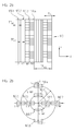
- FIGS. 2a and 2b Let us explain a second variant of a suitable scanning grating 170 for a position-measuring device according to the invention and the resulting arrangement of the detector elements in the detection plane.
- a sampling grid could, for example, be used again in a position-measuring device, as determined by the scanning beam path in the FIGS. 1a and 1b was explained.
- the second exemplary embodiment described below in turn represents a four-phase system in which four phase-shifted, shift-dependent modulated incremental signals S_0 °, S_90 °, S_180 ° and S_270 ° each result in a 90 ° phase offset.
- n 4 grating sections 170.1 - 170.4 are provided in the scanning grating 170, which are arranged block by block in the measuring direction x with the fringe pattern period TP S.
- the grating sections 170.1 and 170.3 have the larger grating section periodicity TP G1 , the grating sections 170.2 and 170.4 the smaller grating section periodicity TP G2 .
- the - again rectangular - detector elements with their geometric centers now on two circles with the radii R1 and R2, with R2 2 * R1, arranged.
- the arrangement of the centers of gravity of the detector elements 160.1, 160.3, 160.5 and 160.7 on the circle with the radius R1 the focal points of the detector elements 160.2, 160.4, 160.6 and 160.8 are arranged in the manner shown on the circle with the radius R2.
- the structural elements of the scanning grating 170 are as shown in FIG. 2a can be seen, all aligned parallel or perpendicular to the other gratings in the position measuring device, in particular for measuring graduation of the material measure whose structural elements also extend in the y direction and are arranged periodically in the measuring direction x.
- Such an embodiment of the scanning grating 170 proves to be advantageous in position measuring devices in which, for example, a so-called.
- VCSEL light source is used (vertical cavity surface emitting laser).
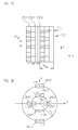
- FIGS. 3a and 3b show partial views of the scanning grid 270 and the detection plane with the there placed detector elements 260.1 - 260.6.
- Such a scanning grating 270 could, for example, also be used again in a position-measuring device, as can be seen from the scanning beam path in FIGS. 1a and 1b was explained.
- the grating sections 270.2 and 270.3 have the larger grating section periodicity TP G1
- the grating section 270.1 has the smaller grating section periodicity TP G2 .
- the arrangement of the geometric centers of gravity of the detector elements 260.2, 260.3, 260.5 and 260.6 on the circle with the radius R1 are arranged in the specified manner on the circle with the radius R2.
- FIGS. 1a and 1b explained scanning beam path for generating a periodic stripe pattern in a scanning plane by no means mandatory for the present invention.
- a striped pattern can also be generated by differently configured material measures and / or scanning units via the interaction of the radiation beam emitted by a light source with the material measure and optional further gratings in the scanning beam path.
- a transmitted-light system with a transmitted-light material measure could also be realized according to the invention.
- a position measuring device for detecting linear movements and a rotary position measuring device can be configured according to the invention, etc.
Landscapes
- Physics & Mathematics (AREA)
- General Physics & Mathematics (AREA)
- Optical Transform (AREA)
- Length Measuring Devices By Optical Means (AREA)
Claims (15)
- Dispositif de mesure de position optique destiné à générer une pluralité de signaux incrémentiels (S_0°, S_90°, S180°, S270° ; S_0°, S_120°, 1_240°) dépendant du déplacement et déphasés par rapport à deux objets mobiles l'un par rapport à l'autre dans une direction de mesure (x), comprenant :- un corps d'étalonnage (20) et- une unité de balayage (10) comportant un réseau de balayage (17 ; 170 ; 270 ; 370) disposé dans un plan de balayage ainsi qu'une pluralité d'éléments détecteurs (16.1 - 16.8 ; 160.1 - 160.8 ; 260.1 - 260.6 ; 360.1 - 360.6), situés en aval du réseau de balayage (17 ; 170 ; 270 ; 370),dans lequel il résulte de l'interaction du faisceau de rayonnement émis par une source de lumière (11) avec le corps d'étalonnage (20) et d'autres réseaux facultatifs sur le chemin du faisceau de balayage dans le plan de balayage, un motif de bandes ayant une périodicité de motif de bande TPS,
caractérisé en ce que- le réseau de balayage (17 ; 170 ; 270 ; 370) destiné à générer tous les signaux incrémentiels (S_0°, S_90°, S180°, S270° ; S_0°, S_120°, 1_240°) est constitué d'une pluralité de blocs disposés périodiquement selon la périodicité de réseau de balayage TPAG = TPS dans la direction de mesure (x), dans lequel chaque bloc n = 3 ou n = 4 comprend des sections de réseau (17.1 - 17.4 ; 170.1 - 170.4 ; 270.1 - 270.3 ; 370.1 - 370.3) agencées dans la direction de mesure (x) de largeur bx = TPAG/n et en ce que chaque section de réseau (17.1 - 17.4 ; 170.1 - 170.4 ; 270.1 - 270.3 ; 370.1 - 370.3) présente une structure de réseau périodique qui produit une déviation dans plusieurs directions spatiales des faisceaux de rayonnement se propageant à travers ladite section de réseau (17.1 - 17.4 ; 170.1 - 170.4 ; 270.1- 270.3 ; 370.1 - 370.3), dans lequel les directions spatiales résultantes des sections de réseaux (17.1 - 17.4 ; 170.1 - 170.4 ; 270.1 - 270.3 ; 370.1 - 370.3) se différencient dans un bloc et- des éléments détecteurs (16.1 - 15.8 ; 160.1 - 160.8 ; 260.1 - 260.6 ; 360.1 - 360.6) sont agencés dans les différentes directions spatiales dans un plan de détection, dans lequel le plan de détection se situe dans une zone dans laquelle les faisceaux de rayonnement provenant du réseau de balayage (17 ; 170 ; 270 ; 370) sont entièrement séparés spatialement. - Dispositif de mesure de position optique selon la revendication 1, caractérisé en ce que les structures de réseaux sont constituées d'éléments structurels ayant des propriétés optiques présentant des différences périodiques agencés périodiquement avec une périodicité de section de réseau TPG, qui sont respectivement disposés à l'intérieur d'une section de réseau (17.1 - 17.4 ; 170.1 - 170.4 ; 270.1 - 270.3 ; 370.1 - 370.3) sous un même angle de torsion (αi) par rapport à un axe (y) perpendiculaire à la direction de mesure (x).
- Dispositif de mesure de position optique selon la revendication 2, caractérisé en ce que pour n=4 sections de réseaux différentes (17.1 - 17.4 ; 170.1 - 170.4) dans un bloc, deux ou quatre angles de torsion différents (αi) sont sélectionnés pour les éléments structurels des sections de réseaux (17.1 - 17.4 ; 170.1 - 170.4 ; 270.1 - 270.3 ; 370.1 - 370.3).
- Dispositif de mesure de position optique selon la revendication 3, caractérisé en ce que
dans le cas de deux angles de torsion différents prévus (αi), ceux-ci sont sélectionnés de manière à ce que α1 = 0°, α2 = 0°, α3 = 90°, α4 = 90°, ou
dans le cas de quatre angles de torsion différents prévus (αi), ceux-ci sont sélectionnés de manière à ce que α1 = 0°, α2 = 30°, α3 = 90°, α4 = -30°. - Dispositif de mesure de position optique selon la revendication 2, caractérisé en ce que pour n = 3 sections de réseaux différentes (270.1 - 270.3 ; 370.1 - 370.3) dans un bloc, deux ou trois angles de torsion différents (αi) sont sélectionnés pour les éléments structurels des sections de réseaux (270.1 - 270.3 ; 370.1 - 370.3).
- Dispositif de mesure de position optique selon la revendication 5, caractérisé en ce que- dans le cas de deux angles de torsion différents prévus (αi), ceux-ci sont sélectionnés de manière à ce que α1 = 90°, α2 = 90°, α3 = 0°, ou- dans le cas de trois angles de torsion différents prévus (αi), ceux-ci sont sélectionnés de manière à ce que α1 = 90°, α2 = 20°, α3 = -20°.
- Dispositif de mesure de position optique selon au moins l'une des revendications précédentes, caractérisé en ce que les structures de réseaux sont réalisées sous la forme de réseaux de phase dans lesquels des éléments structurels différents exercent respectivement un effet de déphasage différent sur les faisceaux de rayonnement incidents.
- Dispositif de mesure de position optique selon au moins l'une des revendications 1-6, caractérisé en ce que les structures de réseaux sont réalisées sous la forme de réseaux d'amplitude dans lesquels des éléments structurels différents possèdent respectivement une transparence différente vis-à-vis des faisceaux de rayonnement incidents sur ceux-ci.
- Dispositif de mesure de position optique selon au moins l'une des revendications précédentes, caractérisé en ce que les éléments détecteurs (16.1 - 16.8 ; 160.1 - 160.8 ; 260.1 - 260.6 ; 360.1 - 360.6) sont réalisés sous forme rectangulaire et possèdent une plus grande longueur dans la direction de mesure (x) que dans une direction (y) perpendiculaire à celle-ci.
- Dispositif de mesure de position optique selon au moins la revendication 2, caractérisé en ce que les différentes sections de réseaux (17.1 - 17.4 ; 370.1 - 370.3) présentent la même périodicité de section de réseau (TPG).
- Dispositif de mesure de position optique selon la revendication 10, caractérisé en ce que les barycentres géométriques des éléments détecteurs (16.1 - 16.8 ; 360.1 - 360.6) sont agencés dans le plan de détection sur un cercle de rayon R.
- Dispositif de mesure de position optique selon la revendication 2, caractérisé en ce que les différentes sections de réseaux (170.1 - 170,4 ; 270.1 - 270.3) présentent deux périodicités de section de réseau différentes (TPG,j).
- Dispositif de mesure de position optique selon la revendication 12, caractérisé en ce que les barycentres géométriques des éléments détecteurs (160.1 - 160.8 ; 260.1 - 260.6) sont agencés dans le plan de détection sur deux cercles de rayons différents (R1, R2).
- Dispositif de mesure de position optique selon au moins l'une des revendications précédentes, caractérisé en ce que l'unité de balayage (10) est conçue de manière à ce que les faisceaux de rayonnement émis par une source de lumière (11)- soient incidents une première fois sur le corps d'étalonnage (20), où il se produit une division en deux faisceaux de rayonnement partiels rétro-réfléchis vers l'unité de balayage (10), ceux-ci correspondant à deux ordres de diffraction différents,- les deux faisceaux de rayonnement partiels rétro-réfléchis sont soumis à une rétro-réflexion dans la direction du corps d'étalonnage (20) dans l'unité de balayage (10) par l'intermédiaire d'un élément rétro-réfléchissant, dans lequel les faisceaux de rayonnement partiels traversent respectivement deux fois les réseaux (14.1, 14.2, 14.3, 14.4),- les faisceaux de rayonnement partiels incidents une deuxième fois sur le corps d'étalonnage (20) sont de nouveau soumis à une diffraction et à une rétro-réflexion dans la direction de l'unité de balayage (10),- au moins une paire de faisceaux de rayonnement partiels rétro-réfléchis dans l'unité de balayage (10) est incidente en un même point sur le réseau balayage (17) sous des angles symétriques (α1, α2) par rapport à l'axe optique (OA).
- Dispositif de mesure de position optique selon au moins l'une des revendications précédentes, caractérisé en ce que, entre le réseau de balayage (17) et les éléments détecteurs disposés en aval (16.1 - 16.8), se trouve une optique de focalisation (18) par l'intermédiaire de laquelle une focalisation des faisceaux de rayonnement partiels déviés dans les différentes directions spatiales est effectuée sur les éléments détecteurs (16.1 - 16.8).
Applications Claiming Priority (1)
| Application Number | Priority Date | Filing Date | Title |
|---|---|---|---|
| DE102008007319A DE102008007319A1 (de) | 2008-02-02 | 2008-02-02 | Optische Positionsmesseinrichtung |
Publications (3)
| Publication Number | Publication Date |
|---|---|
| EP2085752A2 EP2085752A2 (fr) | 2009-08-05 |
| EP2085752A3 EP2085752A3 (fr) | 2013-10-16 |
| EP2085752B1 true EP2085752B1 (fr) | 2014-11-05 |
Family
ID=40668151
Family Applications (1)
| Application Number | Title | Priority Date | Filing Date |
|---|---|---|---|
| EP08171105.3A Active EP2085752B1 (fr) | 2008-02-02 | 2008-12-09 | Dispositif optique de mesure de la position |
Country Status (5)
| Country | Link |
|---|---|
| US (1) | US7872762B2 (fr) |
| EP (1) | EP2085752B1 (fr) |
| JP (1) | JP5710105B2 (fr) |
| DE (1) | DE102008007319A1 (fr) |
| ES (1) | ES2524060T3 (fr) |
Families Citing this family (17)
| Publication number | Priority date | Publication date | Assignee | Title |
|---|---|---|---|---|
| DE102008025870A1 (de) * | 2008-05-31 | 2009-12-03 | Dr. Johannes Heidenhain Gmbh | Optische Positionsmesseinrichtung |
| US8436293B2 (en) * | 2009-02-23 | 2013-05-07 | Christopher C. Chang | Optical encoder and method for measuring displacement information using multiple optical tracks of diffractive optical regions having different periodicities |
| CN102192761B (zh) * | 2010-04-22 | 2013-06-05 | 廊坊开发区莱格光电仪器有限公司 | 敞开式激光限束扫描标尺光栅传感器 |
| DE102010043469A1 (de) * | 2010-11-05 | 2012-05-10 | Dr. Johannes Heidenhain Gmbh | Optische Positionsmesseinrichtung |
| DE102010063253A1 (de) * | 2010-12-16 | 2012-06-21 | Dr. Johannes Heidenhain Gmbh | Optische Positionsmesseinrichtung |
| DE102011076178B4 (de) * | 2011-05-20 | 2022-03-31 | Dr. Johannes Heidenhain Gmbh | Positionsmesseinrichtung |
| DE102011111900A1 (de) | 2011-08-30 | 2013-02-28 | Dr. Johannes Heidenhain Gmbh | Vorrichtung zur interferometrischen Abstandsbestimmung |
| TWI546518B (zh) * | 2012-04-20 | 2016-08-21 | 德律科技股份有限公司 | 三維量測系統與三維量測方法 |
| JP6253929B2 (ja) * | 2013-09-11 | 2017-12-27 | 株式会社オプトニクス精密 | 反射型エンコーダ装置 |
| TWI627379B (zh) * | 2013-10-07 | 2018-06-21 | 德商強那斯海登翰博士有限公司 | 光學位置測量裝置 |
| DE102013220214A1 (de) | 2013-10-07 | 2015-04-09 | Dr. Johannes Heidenhain Gmbh | Anordnung zur Positionierung eines Werkzeugs relativ zu einem Werkstück |
| JP6702666B2 (ja) | 2015-07-28 | 2020-06-03 | 株式会社ミツトヨ | 変位検出装置 |
| JP6400036B2 (ja) * | 2016-03-14 | 2018-10-03 | キヤノン株式会社 | 位置検出装置、工作装置、および、露光装置 |
| CN106971369B (zh) * | 2017-03-02 | 2020-06-12 | 南京师范大学 | 一种基于gpu的地形可视域分析的数据调度与分发方法 |
| DE102018212719A1 (de) * | 2018-07-31 | 2020-02-20 | Dr. Johannes Heidenhain Gesellschaft Mit Beschränkter Haftung | Optische Positionsmesseinrichtung |
| JP7513510B2 (ja) * | 2020-11-24 | 2024-07-09 | 株式会社ミツトヨ | 変位センサ及び形状測定装置 |
| CN115113411B (zh) * | 2022-08-31 | 2022-11-22 | 长春理工大学 | 一种多光束合束装置及方法 |
Family Cites Families (20)
| Publication number | Priority date | Publication date | Assignee | Title |
|---|---|---|---|---|
| CA2073409A1 (fr) * | 1991-10-15 | 1993-04-16 | Paul F. Sullivan | Dispositif utilisant des figures de diffraction pour determiner et commander la position d'un faisceau lumineux |
| JP3198789B2 (ja) * | 1994-04-12 | 2001-08-13 | 松下電器産業株式会社 | 光学式エンコーダ |
| US5497226A (en) * | 1994-08-22 | 1996-03-05 | Polaroid Corporation | Quadrature diffractive encoder |
| DE19511068A1 (de) * | 1995-03-25 | 1996-09-26 | Heidenhain Gmbh Dr Johannes | Lichtelektrische Positionsmeßeinrichtung |
| US5808742A (en) * | 1995-05-31 | 1998-09-15 | Massachusetts Institute Of Technology | Optical alignment apparatus having multiple parallel alignment marks |
| DE19521295C2 (de) * | 1995-06-10 | 2000-07-13 | Heidenhain Gmbh Dr Johannes | Lichtelektrische Positionsmeßeinrichtung |
| DE19748802B4 (de) * | 1996-11-20 | 2010-09-09 | Dr. Johannes Heidenhain Gmbh | Optische Positionsmeßeinrichtung |
| DE19716058B4 (de) * | 1997-04-17 | 2011-03-17 | Dr. Johannes Heidenhain Gmbh | Optische Positionsmeßeinrichtung |
| US6124589A (en) * | 1997-06-16 | 2000-09-26 | West; Donald Lee | Virtual mask encoder |
| US7016025B1 (en) * | 1999-06-24 | 2006-03-21 | Asml Holding N.V. | Method and apparatus for characterization of optical systems |
| DE19962278A1 (de) * | 1999-12-23 | 2001-08-02 | Heidenhain Gmbh Dr Johannes | Positionsmeßeinrichtung |
| US7088458B1 (en) * | 2002-12-23 | 2006-08-08 | Carl Zeiss Smt Ag | Apparatus and method for measuring an optical imaging system, and detector unit |
| US7295315B2 (en) * | 2003-06-30 | 2007-11-13 | Kenneth C. Johnson | Focus and alignment sensors and methods for use with scanning microlens-array printer |
| JP4520121B2 (ja) * | 2003-08-08 | 2010-08-04 | シャープ株式会社 | 光学式エンコーダ |
| DE102005029917A1 (de) | 2005-06-28 | 2007-01-04 | Dr. Johannes Heidenhain Gmbh | Positionsmesseinrichtung |
| DE102005043569A1 (de) * | 2005-09-12 | 2007-03-22 | Dr. Johannes Heidenhain Gmbh | Positionsmesseinrichtung |
| DE102006041357A1 (de) * | 2005-11-09 | 2007-05-10 | Dr. Johannes Heidenhain Gmbh | Positionsmesseinrichtung und Verfahren zum Betrieb einer Positionsmesseinrichtung |
| US7636165B2 (en) * | 2006-03-21 | 2009-12-22 | Asml Netherlands B.V. | Displacement measurement systems lithographic apparatus and device manufacturing method |
| DE102006042743A1 (de) * | 2006-09-12 | 2008-03-27 | Dr. Johannes Heidenhain Gmbh | Positionsmesseinrichtung |
| US7561280B2 (en) * | 2007-03-15 | 2009-07-14 | Agilent Technologies, Inc. | Displacement measurement sensor head and system having measurement sub-beams comprising zeroth order and first order diffraction components |
-
2008
- 2008-02-02 DE DE102008007319A patent/DE102008007319A1/de not_active Withdrawn
- 2008-12-09 ES ES08171105.3T patent/ES2524060T3/es active Active
- 2008-12-09 EP EP08171105.3A patent/EP2085752B1/fr active Active
-
2009
- 2009-01-23 US US12/321,642 patent/US7872762B2/en active Active
- 2009-01-30 JP JP2009019213A patent/JP5710105B2/ja active Active
Also Published As
| Publication number | Publication date |
|---|---|
| EP2085752A3 (fr) | 2013-10-16 |
| ES2524060T3 (es) | 2014-12-03 |
| US7872762B2 (en) | 2011-01-18 |
| US20090195792A1 (en) | 2009-08-06 |
| JP2009186471A (ja) | 2009-08-20 |
| DE102008007319A1 (de) | 2009-08-06 |
| EP2085752A2 (fr) | 2009-08-05 |
| JP5710105B2 (ja) | 2015-04-30 |
Similar Documents
| Publication | Publication Date | Title |
|---|---|---|
| EP2085752B1 (fr) | Dispositif optique de mesure de la position | |
| EP2149036B1 (fr) | Dispositif de mesure de position optique | |
| EP1901041B1 (fr) | Dispositif de mesure de position | |
| EP1739395B1 (fr) | Dispositif de mesure de position | |
| EP1319170B1 (fr) | Dispositif de mesure de position | |
| EP1396704B1 (fr) | Dispositif interferentiel de mesure de position | |
| EP1923673B1 (fr) | Dispositif de mesure de position | |
| DE19830925A1 (de) | Abtasteinheit für eine optische Positionsmeßeinrichtung | |
| EP2450672B1 (fr) | Dispositif de mesure d'angle optique | |
| EP2623937B1 (fr) | Dispositif de mesure de position et agencement à plusieurs dispositifs de mesure de position | |
| EP0669518B1 (fr) | Dispositif pour générer des signaux dépendants de la position | |
| DE10058239B4 (de) | Positionsmeßeinrichtung | |
| EP3258220B1 (fr) | Dispositif optique de mesure de position | |
| DE19938869B4 (de) | Optisches Verschiebungsmeßsystem | |
| DE102011076178A1 (de) | Positionsmesseinrichtung | |
| EP1028309B1 (fr) | Codeur optique | |
| EP3477264B1 (fr) | Dispositif optique de mesure de position | |
| EP0754933B1 (fr) | Dispositif de mesure de positions | |
| EP1085291B1 (fr) | Dispsitif pour la détermination de positions et de défaults de translation | |
| DE102007028943A1 (de) | Abtasteinheit für eine optische Positionsmesseinrichtung | |
| WO2014170066A1 (fr) | Dispositif de mesure de distance interférentielle | |
| EP3936830B1 (fr) | Dispositif optique de mesure de la position | |
| DE19922009B4 (de) | Rotatorische Positionsmeßeinrichtung | |
| EP4170291B1 (fr) | Dispositif optique de mesure de position | |
| DE3928064A1 (de) | Lichtelektrische positionsmesseinrichtung |
Legal Events
| Date | Code | Title | Description |
|---|---|---|---|
| PUAI | Public reference made under article 153(3) epc to a published international application that has entered the european phase |
Free format text: ORIGINAL CODE: 0009012 |
|
| AK | Designated contracting states |
Kind code of ref document: A2 Designated state(s): AT BE BG CH CY CZ DE DK EE ES FI FR GB GR HR HU IE IS IT LI LT LU LV MC MT NL NO PL PT RO SE SI SK TR |
|
| AX | Request for extension of the european patent |
Extension state: AL BA MK RS |
|
| PUAL | Search report despatched |
Free format text: ORIGINAL CODE: 0009013 |
|
| AK | Designated contracting states |
Kind code of ref document: A3 Designated state(s): AT BE BG CH CY CZ DE DK EE ES FI FR GB GR HR HU IE IS IT LI LT LU LV MC MT NL NO PL PT RO SE SI SK TR |
|
| AX | Request for extension of the european patent |
Extension state: AL BA MK RS |
|
| RIC1 | Information provided on ipc code assigned before grant |
Ipc: G01D 5/38 20060101AFI20130910BHEP |
|
| 17P | Request for examination filed |
Effective date: 20140416 |
|
| RBV | Designated contracting states (corrected) |
Designated state(s): AT BE BG CH CY CZ DE DK EE ES FI FR GB GR HR HU IE IS IT LI LT LU LV MC MT NL NO PL PT RO SE SI SK TR |
|
| AKX | Designation fees paid |
Designated state(s): AT BE BG CH CY CZ DE DK EE ES FI FR GB GR HR HU IE IS IT LI LT LU LV MC MT NL NO PL PT RO SE SI SK TR |
|
| GRAP | Despatch of communication of intention to grant a patent |
Free format text: ORIGINAL CODE: EPIDOSNIGR1 |
|
| INTG | Intention to grant announced |
Effective date: 20140723 |
|
| GRAS | Grant fee paid |
Free format text: ORIGINAL CODE: EPIDOSNIGR3 |
|
| GRAA | (expected) grant |
Free format text: ORIGINAL CODE: 0009210 |
|
| AK | Designated contracting states |
Kind code of ref document: B1 Designated state(s): AT BE BG CH CY CZ DE DK EE ES FI FR GB GR HR HU IE IS IT LI LT LU LV MC MT NL NO PL PT RO SE SI SK TR |
|
| REG | Reference to a national code |
Ref country code: GB Ref legal event code: FG4D Free format text: NOT ENGLISH |
|
| REG | Reference to a national code |
Ref country code: CH Ref legal event code: NV Representative=s name: ICB INGENIEURS CONSEILS EN BREVETS SA, CH Ref country code: CH Ref legal event code: EP |
|
| REG | Reference to a national code |
Ref country code: AT Ref legal event code: REF Ref document number: 694870 Country of ref document: AT Kind code of ref document: T Effective date: 20141115 |
|
| REG | Reference to a national code |
Ref country code: IE Ref legal event code: FG4D Free format text: LANGUAGE OF EP DOCUMENT: GERMAN Ref country code: ES Ref legal event code: FG2A Ref document number: 2524060 Country of ref document: ES Kind code of ref document: T3 Effective date: 20141203 |
|
| REG | Reference to a national code |
Ref country code: DE Ref legal event code: R096 Ref document number: 502008012374 Country of ref document: DE Effective date: 20141218 |
|
| REG | Reference to a national code |
Ref country code: NL Ref legal event code: VDEP Effective date: 20141105 |
|
| REG | Reference to a national code |
Ref country code: LT Ref legal event code: MG4D |
|
| PG25 | Lapsed in a contracting state [announced via postgrant information from national office to epo] |
Ref country code: NO Free format text: LAPSE BECAUSE OF FAILURE TO SUBMIT A TRANSLATION OF THE DESCRIPTION OR TO PAY THE FEE WITHIN THE PRESCRIBED TIME-LIMIT Effective date: 20150205 Ref country code: IS Free format text: LAPSE BECAUSE OF FAILURE TO SUBMIT A TRANSLATION OF THE DESCRIPTION OR TO PAY THE FEE WITHIN THE PRESCRIBED TIME-LIMIT Effective date: 20150305 Ref country code: FI Free format text: LAPSE BECAUSE OF FAILURE TO SUBMIT A TRANSLATION OF THE DESCRIPTION OR TO PAY THE FEE WITHIN THE PRESCRIBED TIME-LIMIT Effective date: 20141105 Ref country code: PT Free format text: LAPSE BECAUSE OF FAILURE TO SUBMIT A TRANSLATION OF THE DESCRIPTION OR TO PAY THE FEE WITHIN THE PRESCRIBED TIME-LIMIT Effective date: 20150305 Ref country code: LT Free format text: LAPSE BECAUSE OF FAILURE TO SUBMIT A TRANSLATION OF THE DESCRIPTION OR TO PAY THE FEE WITHIN THE PRESCRIBED TIME-LIMIT Effective date: 20141105 Ref country code: NL Free format text: LAPSE BECAUSE OF FAILURE TO SUBMIT A TRANSLATION OF THE DESCRIPTION OR TO PAY THE FEE WITHIN THE PRESCRIBED TIME-LIMIT Effective date: 20141105 |
|
| PG25 | Lapsed in a contracting state [announced via postgrant information from national office to epo] |
Ref country code: LV Free format text: LAPSE BECAUSE OF FAILURE TO SUBMIT A TRANSLATION OF THE DESCRIPTION OR TO PAY THE FEE WITHIN THE PRESCRIBED TIME-LIMIT Effective date: 20141105 Ref country code: HR Free format text: LAPSE BECAUSE OF FAILURE TO SUBMIT A TRANSLATION OF THE DESCRIPTION OR TO PAY THE FEE WITHIN THE PRESCRIBED TIME-LIMIT Effective date: 20141105 Ref country code: CY Free format text: LAPSE BECAUSE OF FAILURE TO SUBMIT A TRANSLATION OF THE DESCRIPTION OR TO PAY THE FEE WITHIN THE PRESCRIBED TIME-LIMIT Effective date: 20141105 Ref country code: GR Free format text: LAPSE BECAUSE OF FAILURE TO SUBMIT A TRANSLATION OF THE DESCRIPTION OR TO PAY THE FEE WITHIN THE PRESCRIBED TIME-LIMIT Effective date: 20150206 Ref country code: PL Free format text: LAPSE BECAUSE OF FAILURE TO SUBMIT A TRANSLATION OF THE DESCRIPTION OR TO PAY THE FEE WITHIN THE PRESCRIBED TIME-LIMIT Effective date: 20141105 Ref country code: SE Free format text: LAPSE BECAUSE OF FAILURE TO SUBMIT A TRANSLATION OF THE DESCRIPTION OR TO PAY THE FEE WITHIN THE PRESCRIBED TIME-LIMIT Effective date: 20141105 |
|
| PG25 | Lapsed in a contracting state [announced via postgrant information from national office to epo] |
Ref country code: BE Free format text: LAPSE BECAUSE OF NON-PAYMENT OF DUE FEES Effective date: 20141231 |
|
| PG25 | Lapsed in a contracting state [announced via postgrant information from national office to epo] |
Ref country code: RO Free format text: LAPSE BECAUSE OF FAILURE TO SUBMIT A TRANSLATION OF THE DESCRIPTION OR TO PAY THE FEE WITHIN THE PRESCRIBED TIME-LIMIT Effective date: 20141105 Ref country code: CZ Free format text: LAPSE BECAUSE OF FAILURE TO SUBMIT A TRANSLATION OF THE DESCRIPTION OR TO PAY THE FEE WITHIN THE PRESCRIBED TIME-LIMIT Effective date: 20141105 Ref country code: SK Free format text: LAPSE BECAUSE OF FAILURE TO SUBMIT A TRANSLATION OF THE DESCRIPTION OR TO PAY THE FEE WITHIN THE PRESCRIBED TIME-LIMIT Effective date: 20141105 Ref country code: DK Free format text: LAPSE BECAUSE OF FAILURE TO SUBMIT A TRANSLATION OF THE DESCRIPTION OR TO PAY THE FEE WITHIN THE PRESCRIBED TIME-LIMIT Effective date: 20141105 Ref country code: EE Free format text: LAPSE BECAUSE OF FAILURE TO SUBMIT A TRANSLATION OF THE DESCRIPTION OR TO PAY THE FEE WITHIN THE PRESCRIBED TIME-LIMIT Effective date: 20141105 |
|
| REG | Reference to a national code |
Ref country code: DE Ref legal event code: R097 Ref document number: 502008012374 Country of ref document: DE |
|
| PG25 | Lapsed in a contracting state [announced via postgrant information from national office to epo] |
Ref country code: MC Free format text: LAPSE BECAUSE OF FAILURE TO SUBMIT A TRANSLATION OF THE DESCRIPTION OR TO PAY THE FEE WITHIN THE PRESCRIBED TIME-LIMIT Effective date: 20141105 |
|
| PLBE | No opposition filed within time limit |
Free format text: ORIGINAL CODE: 0009261 |
|
| STAA | Information on the status of an ep patent application or granted ep patent |
Free format text: STATUS: NO OPPOSITION FILED WITHIN TIME LIMIT |
|
| REG | Reference to a national code |
Ref country code: IE Ref legal event code: MM4A |
|
| REG | Reference to a national code |
Ref country code: FR Ref legal event code: ST Effective date: 20150831 |
|
| 26N | No opposition filed |
Effective date: 20150806 |
|
| PG25 | Lapsed in a contracting state [announced via postgrant information from national office to epo] |
Ref country code: IE Free format text: LAPSE BECAUSE OF NON-PAYMENT OF DUE FEES Effective date: 20141209 |
|
| PG25 | Lapsed in a contracting state [announced via postgrant information from national office to epo] |
Ref country code: FR Free format text: LAPSE BECAUSE OF NON-PAYMENT OF DUE FEES Effective date: 20150105 |
|
| PG25 | Lapsed in a contracting state [announced via postgrant information from national office to epo] |
Ref country code: IT Free format text: LAPSE BECAUSE OF FAILURE TO SUBMIT A TRANSLATION OF THE DESCRIPTION OR TO PAY THE FEE WITHIN THE PRESCRIBED TIME-LIMIT Effective date: 20141105 |
|
| REG | Reference to a national code |
Ref country code: AT Ref legal event code: MM01 Ref document number: 694870 Country of ref document: AT Kind code of ref document: T Effective date: 20141209 |
|
| PG25 | Lapsed in a contracting state [announced via postgrant information from national office to epo] |
Ref country code: SI Free format text: LAPSE BECAUSE OF FAILURE TO SUBMIT A TRANSLATION OF THE DESCRIPTION OR TO PAY THE FEE WITHIN THE PRESCRIBED TIME-LIMIT Effective date: 20141105 |
|
| PG25 | Lapsed in a contracting state [announced via postgrant information from national office to epo] |
Ref country code: BG Free format text: LAPSE BECAUSE OF FAILURE TO SUBMIT A TRANSLATION OF THE DESCRIPTION OR TO PAY THE FEE WITHIN THE PRESCRIBED TIME-LIMIT Effective date: 20141105 Ref country code: AT Free format text: LAPSE BECAUSE OF NON-PAYMENT OF DUE FEES Effective date: 20141209 |
|
| PG25 | Lapsed in a contracting state [announced via postgrant information from national office to epo] |
Ref country code: MT Free format text: LAPSE BECAUSE OF FAILURE TO SUBMIT A TRANSLATION OF THE DESCRIPTION OR TO PAY THE FEE WITHIN THE PRESCRIBED TIME-LIMIT Effective date: 20141105 Ref country code: LU Free format text: LAPSE BECAUSE OF NON-PAYMENT OF DUE FEES Effective date: 20141209 Ref country code: TR Free format text: LAPSE BECAUSE OF FAILURE TO SUBMIT A TRANSLATION OF THE DESCRIPTION OR TO PAY THE FEE WITHIN THE PRESCRIBED TIME-LIMIT Effective date: 20141105 Ref country code: HU Free format text: LAPSE BECAUSE OF FAILURE TO SUBMIT A TRANSLATION OF THE DESCRIPTION OR TO PAY THE FEE WITHIN THE PRESCRIBED TIME-LIMIT; INVALID AB INITIO Effective date: 20081209 |
|
| PGFP | Annual fee paid to national office [announced via postgrant information from national office to epo] |
Ref country code: CH Payment date: 20221213 Year of fee payment: 15 |
|
| PGFP | Annual fee paid to national office [announced via postgrant information from national office to epo] |
Ref country code: GB Payment date: 20231220 Year of fee payment: 16 |
|
| PGFP | Annual fee paid to national office [announced via postgrant information from national office to epo] |
Ref country code: DE Payment date: 20231214 Year of fee payment: 16 |
|
| PGFP | Annual fee paid to national office [announced via postgrant information from national office to epo] |
Ref country code: ES Payment date: 20240126 Year of fee payment: 16 |
|
| REG | Reference to a national code |
Ref country code: CH Ref legal event code: PL |