EP2085752B1 - Optical positioning device - Google Patents
Optical positioning device Download PDFInfo
- Publication number
- EP2085752B1 EP2085752B1 EP08171105.3A EP08171105A EP2085752B1 EP 2085752 B1 EP2085752 B1 EP 2085752B1 EP 08171105 A EP08171105 A EP 08171105A EP 2085752 B1 EP2085752 B1 EP 2085752B1
- Authority
- EP
- European Patent Office
- Prior art keywords
- grid
- scanning
- measuring device
- different
- position measuring
- Prior art date
- Legal status (The legal status is an assumption and is not a legal conclusion. Google has not performed a legal analysis and makes no representation as to the accuracy of the status listed.)
- Active
Links
- 230000003287 optical effect Effects 0.000 title claims description 35
- 238000001514 detection method Methods 0.000 claims description 30
- 239000000463 material Substances 0.000 claims description 28
- 230000000737 periodic effect Effects 0.000 claims description 13
- 230000001419 dependent effect Effects 0.000 claims description 12
- 230000000694 effects Effects 0.000 claims description 10
- 230000003993 interaction Effects 0.000 claims description 5
- 230000001902 propagating effect Effects 0.000 claims description 5
- 230000005855 radiation Effects 0.000 description 13
- 238000005070 sampling Methods 0.000 description 8
- 230000005484 gravity Effects 0.000 description 7
- 239000003795 chemical substances by application Substances 0.000 description 5
- 238000006073 displacement reaction Methods 0.000 description 3
- 230000010287 polarization Effects 0.000 description 3
- 239000000758 substrate Substances 0.000 description 3
- 238000011109 contamination Methods 0.000 description 2
- 238000011156 evaluation Methods 0.000 description 2
- 230000007274 generation of a signal involved in cell-cell signaling Effects 0.000 description 2
- 238000009434 installation Methods 0.000 description 2
- 238000005259 measurement Methods 0.000 description 2
- 230000035699 permeability Effects 0.000 description 2
- 230000005540 biological transmission Effects 0.000 description 1
- 238000006243 chemical reaction Methods 0.000 description 1
- 239000000356 contaminant Substances 0.000 description 1
- 230000009977 dual effect Effects 0.000 description 1
- 238000000605 extraction Methods 0.000 description 1
- 239000011521 glass Substances 0.000 description 1
- 238000005286 illumination Methods 0.000 description 1
- 238000004519 manufacturing process Methods 0.000 description 1
- 230000035945 sensitivity Effects 0.000 description 1
Images


Classifications
-
- G—PHYSICS
- G01—MEASURING; TESTING
- G01D—MEASURING NOT SPECIALLY ADAPTED FOR A SPECIFIC VARIABLE; ARRANGEMENTS FOR MEASURING TWO OR MORE VARIABLES NOT COVERED IN A SINGLE OTHER SUBCLASS; TARIFF METERING APPARATUS; MEASURING OR TESTING NOT OTHERWISE PROVIDED FOR
- G01D5/00—Mechanical means for transferring the output of a sensing member; Means for converting the output of a sensing member to another variable where the form or nature of the sensing member does not constrain the means for converting; Transducers not specially adapted for a specific variable
- G01D5/26—Mechanical means for transferring the output of a sensing member; Means for converting the output of a sensing member to another variable where the form or nature of the sensing member does not constrain the means for converting; Transducers not specially adapted for a specific variable characterised by optical transfer means, i.e. using infrared, visible, or ultraviolet light
- G01D5/32—Mechanical means for transferring the output of a sensing member; Means for converting the output of a sensing member to another variable where the form or nature of the sensing member does not constrain the means for converting; Transducers not specially adapted for a specific variable characterised by optical transfer means, i.e. using infrared, visible, or ultraviolet light with attenuation or whole or partial obturation of beams of light
- G01D5/34—Mechanical means for transferring the output of a sensing member; Means for converting the output of a sensing member to another variable where the form or nature of the sensing member does not constrain the means for converting; Transducers not specially adapted for a specific variable characterised by optical transfer means, i.e. using infrared, visible, or ultraviolet light with attenuation or whole or partial obturation of beams of light the beams of light being detected by photocells
- G01D5/36—Forming the light into pulses
- G01D5/38—Forming the light into pulses by diffraction gratings
Definitions
- the present invention relates to an optical position measuring device which is suitable for determining the relative position of two mutually movable objects.
- periodic fringe patterns are generated via the interaction of a radiation beam emitted by a light source with a material measure and optionally further gratings in the scanning beam path.
- the material measure and a scanning unit results in an intensity modulation of the fringe pattern, which can be evaluated to generate displacement-dependent incremental signals.
- Such an evaluation can be carried out, for example, via so-called structured photodetectors, which consist of a periodic arrangement of photodiodes. The periodicity of the detector arrangement is matched to the periodicity of the stripe pattern, depending on the number of phase-shifted incremental signals.
- Object of the present invention is to provide an optical position measuring device that allows reliable detection of fine stripe patterns in a scanning plane with high efficiency and the greatest possible insensitivity to contamination of the material measure.
- Each grating section has a periodic grating structure which effects a deflection of the beam propagating through this grating section in a plurality of spatial directions. The resulting spatial directions of the grating sections in a block differ.
- the detection plane lies in an area in which the radiation beams coming from the scanning grating are completely spatially separated.
- the optical position measuring device consists of generating n> 1 phase-shifted, shift-dependent incremental signals with respect to two objects movable in one measuring direction from a material measure and a scanning unit having a scanning grid arranged in a scanning plane and a plurality of detector elements arranged downstream of the scanning grid. wherein a fringe pattern with the fringe pattern periodicity TP S results from the interaction of the radiation beam emitted by a light source with the material measure and optional further gratings in the scanning beam path in the scanning plane.
- Detector elements are arranged in the different spatial directions in a detection plane, wherein the detection plane lies in a region in which the radiation beams coming from the scanning grating are completely spatially separated.
- the grating structures consist of periodically arranged with the grating section periodicity TP G structural elements with alternately different optical properties, which are each arranged within a grating section at the same angle of rotation to an axis perpendicular to the measuring direction.
- n 4 different grid sections in a block
- two or four different angles of rotation for the structural elements of the grid sections can be selected.
- n 3 different grating sections in a block
- two or three different angles of rotation can be selected for the structural elements of the grating sections.
- the grating structures may be formed as phase gratings, in which different structural elements each exert a different phase-shifting effect on the incident radiation beam.
- the grating structures may also be formed as amplitude gratings, in which different structural elements each have a different permeability to the radiation beam incident thereon.
- the detector elements are rectangular in shape and have a greater length in the measuring direction than in the direction perpendicular thereto.
- the different grid sections may have the same grid section periodicity.
- the geometric center of gravity of the detector elements in the detection plane it is possible for the geometric center of gravity of the detector elements in the detection plane to be arranged on a circle with the radius R.
- the geometric centers of gravity of the detector elements in the detection plane can be arranged on two circles with different radii.
- a focusing optics can be arranged between the scanning grating and the downstream detector elements, via which a focusing of the deflected in the different spatial directions partial beams on the detector elements.
- FIGS. 1a-1d a first embodiment of the position-measuring device according to the invention, in particular of the scanning grating used in this case, will be explained.
- the FIGS. 1a and 1b show in each case in schematic form partial scanning beam paths in a lateral view in the xz plane.
- FIG. 1a is the scanning beam from the light source 11 to the impingement of the partial beams on the reflector elements 15.1, 15.2,
- FIG. 1b shows the scanning beam from the impingement of the partial beams on the reflector elements 15.1, 15.2 to the detector elements 16.1 - 16.5.
- the Figures 1c and 1d show partial views of the scanning grating 17 and the detection plane of this embodiment.
- the position measuring device comprises in this example a measuring standard 20, designed as a reflection measuring graduation, and a scanning unit 10 movable relative thereto in at least one measuring direction x.
- the objects are coupled in a known manner to the reflection measuring standard 20 and the scanning unit 10, whose relative position is to be determined by means of the position measuring device. These may be, for example, machine parts whose relative position must be precisely recorded.
- the incremental signals or position data generated by means of the position-measuring device according to the invention are further processed by an electronic follower or evaluation unit (not shown), for example for controlling the machine.
- a position measuring device for detecting linear movements with a linearly extending material measure 20 is shown;
- rotary position measuring devices based on the inventive considerations can be realized.
- the carrier substrate 13.1 is formed as a plane-parallel glass plate. On the top and bottom are different arranged optical elements, their specific function in the scanning beam will be discussed in detail below.
- the measuring graduation 22 consists of a measurement scale x periodic arrangement of structural elements or partial areas 22.1, 22.2 with different optical reflection properties.
- the line-shaped partial areas 22.1, 22.2 extend perpendicular to the measuring direction x in the indicated direction y (also referred to below as the line direction) and are arranged on a carrier body 21 of the reflection measuring graduation 20.
- the measuring graduation 22 is designed as incident-light phase grating, in which the structural elements or partial regions 22.1, 22.2 have a different phase-shifting effect on the radiation beam arriving thereon.
- the division period of the measuring graduation 22 is referred to below as TP M and is defined as the length of two successive partial regions 22.1, 22.2 in the measuring direction x.
- a splitting of the incident beam results in two partial beams reflected back to the scanning unit 10, which correspond to the +/- 1st diffraction orders.
- the back-reflected partial beams first pass through the in FIG. 1a shown gratings 14.1, 14.2 on the underside of the scanning 13.
- the grids 14.1, 14.2 are formed in the present example as a transmission grating.
- the gratings 14.1, 14.2 are the partial beams in a defined manner deflected and then arrive at plane reflector elements 15.1, 15.2. on the upper side of the scanning plate 13.
- the two first traversed gratings 14.1, 14.2 have the same pitch period, which is referred to below as TP G1 .
- the division period TP G1 of the gratings 14.1, 14.2 is selected differently from the graduation period TP M of the measurement graduation 22. Due to this choice of the pitch periods TP G1 , the partial beams do not propagate perpendicularly to the scanning plate 13 after passing through the grids 14.1, 14.2.
- the partial beams travel through the two further gratings 14.3, 14.4, which are shown on the reflector elements 15.1, 15.2 are also arranged on the underside of the scanning 13.
- the transmitted partial beams are deflected again in the direction of the respective second impact location on the material measure 20.
- the two grids 14.3, 14.4 which now pass through have the same graduation period, which is referred to below as TP G2 .
- the gratings 14.1-14.4 have a dual optical function. On the one hand, they act in the measuring direction x like a regularly periodic deflection grating with the division periods TP G1 or TP G2 . On the other hand, in the line direction y in the material scale, they act like cylindrical lenses which focus the incident beams onto the reflector elements 15.1, 15.2 and subsequently collimate again. In the example shown the FIGS. 1a and 1b focus the grids 14.1, 14.2, while the grids 14.3, 14.4 again collimate the exiting beams.
- the combination of reflector element and lens provides - as in the DE 10 2005 029 917.2
- the sampling gratings In order for the sampling gratings to be able to perform all these optical functions at the same time, they have to be formed as grids with curved grating lines, as is mentioned in the above-mentioned DE 10 2005 029 917.2 described and in the following Fig. 1d is indicated schematically; In the following, with regard to such lattice structures, reference will also be made to diffractive deflection / lens elements.
- the structural unit consisting of the scanning 13 with the support substrate 13.1, the gratings 14.1, 14.2, 14.3, 14.4 and the planar reflector elements 15.1, 15.2 acts in the illustrated first embodiment, therefore, as a retroreflector element on the part of the scanning unit 10. About this there is a return deflection the coming of the material measure 20 partial beam in the direction of the material measure 20 to apply this a second time. The retroreflection takes place here in the specified y-direction.
- a shift-dependent modulated stripe pattern having a stripe pattern periodicity TP S In the case of the relative displacement of material measure 20 and scanning unit 10 results due to the interaction of the beam with the material measure and the various grids in the scanning beam in the scanning plane, a shift-dependent modulated stripe pattern having a stripe pattern periodicity TP S.
- the spatially periodic intensity distribution of the fringe pattern in the scanning plane is converted to different locations in the detection plane via the scanning grating 17, for which purpose an additional focusing optical system 18 is provided in the present example.
- an additional focusing optical system 18 is provided in the present example.
- locations in the stripe pattern with the same properties are assigned the same spatial propagation directions.
- the detection plane which lies in an area in which the radiation beams coming from the scanning grating 17 are completely spatially separated, a total of eight detector elements 16.1-16.5 are arranged in the different spatial directions. About the detector elements 16.1 -16.5, the shift-dependent, phase-shifted incremental signals are detected, wherein in FIG. 1b not all detector elements are shown.
- the focusing optics 18 provided in this exemplary embodiment are not fundamentally necessary in this case, but allow the focusing of partial beams of the same direction of propagation from the scanning grating 17 to particularly small detector elements 16.1-16.5. This in turn allows a compact design of the scanning unit 10. Due to the smaller detector element areas, the detector elements also have small capacitances, so that the signal noise is reduced. In addition, due to the focusing optics larger beam cross sections can be used for scanning, without increasing the height of the scanning unit or the capacitance of the detector elements. In turn, larger scanning areas result in more stable incremental signals.
- FIGS. 1a and 1b used sample grid shows Figure 1c in conjunction with a part of the stripe pattern S resulting in the scanning plane, which has the stripe pattern periodicity TP S.
- the stripe pattern periodicity TP S 30 ⁇ m.
- the grating sections 17.1 - 17.4 are each rectangular in shape and extend in the longitudinal direction in the specified y-direction, ie perpendicular to the measuring direction x.
- the sampling grid periodicity TP AG in which the blocks are arranged corresponds to the stripe pattern periodicity TP S.
- the resulting spatial directions of the grating sections 17.1 - 17.4 differ within a block.
- the four differently shaped grating sections 17.1-17.4 cause due to their respective design a different spatial deflection effect on the incident thereon beam.
- the grating sections each have periodic grating structures with periodically arranged structural elements which have different optical properties.
- the different optical properties are, for example, different phase-shifting effects or else different permeabilities.
- the structural elements of an amplitude grating may be periodically arranged, permeable and non-transparent subregions, etc.
- the structural elements are arranged periodically within the respective grid sections, the periodicity of the structural elements in the grid sections being referred to below as the grid section periodicity TP G.
- each grating section 17.1 - 17.4 at least one deflection of the radiation beam impinging thereon takes place in two spatial directions, namely at least one deflection into the +1. and in the -1. Diffraction order. Possibly. Further diffraction orders are not evaluated in the case of the present example for signal extraction.
- the incremental signal S_0 ° is accordingly generated from the grating sections 17.1 of the scanning grating 17, the incremental signal S_90 ° from the grating sections 17.2, the incremental signal S_180 ° from the grating sections 17.3 and the incremental signal S_270 ° from the grating sections 17.4.
- the present first exemplary embodiment thus represents a four-phase system whose four phase-shifted incremental signals S_0 °, S_90 °, S_180 °, S_270 ° can be evaluated in a known manner.
- detector elements 16.1-16.8 are arranged in the different spatial directions, into which a corresponding deflection effect in the +/- 1 .fraction orders results from the grating sections 17.1-17.4, as shown in FIG Figure 1d is shown.
- the described first embodiment of a suitable scanning grid ensures optimum space utilization in the detection plane and reduces the required installation space in the scanning unit.
- further embodiments of scanning gratings are explained for the position measuring device according to the invention, which are optimized with respect to other requirements.
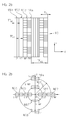
- FIGS. 2a and 2b Let us explain a second variant of a suitable scanning grating 170 for a position-measuring device according to the invention and the resulting arrangement of the detector elements in the detection plane.
- a sampling grid could, for example, be used again in a position-measuring device, as determined by the scanning beam path in the FIGS. 1a and 1b was explained.
- the second exemplary embodiment described below in turn represents a four-phase system in which four phase-shifted, shift-dependent modulated incremental signals S_0 °, S_90 °, S_180 ° and S_270 ° each result in a 90 ° phase offset.
- n 4 grating sections 170.1 - 170.4 are provided in the scanning grating 170, which are arranged block by block in the measuring direction x with the fringe pattern period TP S.
- the grating sections 170.1 and 170.3 have the larger grating section periodicity TP G1 , the grating sections 170.2 and 170.4 the smaller grating section periodicity TP G2 .
- the - again rectangular - detector elements with their geometric centers now on two circles with the radii R1 and R2, with R2 2 * R1, arranged.
- the arrangement of the centers of gravity of the detector elements 160.1, 160.3, 160.5 and 160.7 on the circle with the radius R1 the focal points of the detector elements 160.2, 160.4, 160.6 and 160.8 are arranged in the manner shown on the circle with the radius R2.
- the structural elements of the scanning grating 170 are as shown in FIG. 2a can be seen, all aligned parallel or perpendicular to the other gratings in the position measuring device, in particular for measuring graduation of the material measure whose structural elements also extend in the y direction and are arranged periodically in the measuring direction x.
- Such an embodiment of the scanning grating 170 proves to be advantageous in position measuring devices in which, for example, a so-called.
- VCSEL light source is used (vertical cavity surface emitting laser).
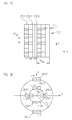
- FIGS. 3a and 3b show partial views of the scanning grid 270 and the detection plane with the there placed detector elements 260.1 - 260.6.
- Such a scanning grating 270 could, for example, also be used again in a position-measuring device, as can be seen from the scanning beam path in FIGS. 1a and 1b was explained.
- the grating sections 270.2 and 270.3 have the larger grating section periodicity TP G1
- the grating section 270.1 has the smaller grating section periodicity TP G2 .
- the arrangement of the geometric centers of gravity of the detector elements 260.2, 260.3, 260.5 and 260.6 on the circle with the radius R1 are arranged in the specified manner on the circle with the radius R2.
- FIGS. 1a and 1b explained scanning beam path for generating a periodic stripe pattern in a scanning plane by no means mandatory for the present invention.
- a striped pattern can also be generated by differently configured material measures and / or scanning units via the interaction of the radiation beam emitted by a light source with the material measure and optional further gratings in the scanning beam path.
- a transmitted-light system with a transmitted-light material measure could also be realized according to the invention.
- a position measuring device for detecting linear movements and a rotary position measuring device can be configured according to the invention, etc.
Description
Die vorliegende Erfindung betrifft eine optische Positionsmesseinrichtung, die zur Bestimmung der Relativposition zweier zueinander beweglicher Objekte geeignet ist.The present invention relates to an optical position measuring device which is suitable for determining the relative position of two mutually movable objects.
In bekannten optischen Positionsmesseinrichtungen werden über die Wechselwirkung eines von einer Lichtquelle emittierten Strahlenbündels mit einer Maßverkörperung und ggf. weiteren Gittern im Abtaststrahlengang periodische Streifenmuster erzeugt. Im Fall der Relativbewegung bestimmter Komponenten der Positionsmesseinrichtung, üblicherweise der Maßverkörperung und einer Abtasteinheit, resultiert eine Intensitätsmodulation des Streifenmusters, die zur Erzeugung verschiebungsabhängiger Inkrementalsignale ausgewertet werden kann. Eine derartige Auswertung kann beispielsweise über sog. strukturierte Photodetektoren erfolgen, die aus einer periodischen Anordnung von Photodioden bestehen. Die Periodizität der Detektor-Anordnung wird je nach Anzahl der phasenverschobenen Inkrementalsignale auf die Periodizität des Streifenmusters abgestimmt. Im Fall höher auflösender optischer Positionsmesseinrichtungen ergeben sich immer feinere Streifenmuster, d.h. die Periodizität derselben verringert sich entsprechend; ebenso verringert sich dann die erforderliche Breite der Photodioden in einem zur Abtastung derartiger Streifenmuster genutzten strukturierten Photodetektor. Aufgrund fertigungsbedingter Einschränkungen kann die Breite der Photodioden in einer solchen Anordnung eine bestimmte Minimalbreite nicht unterschreiten. Ab einer Streifenmusterperiode von etwa 40µm stehen keine geeigneten strukturierten Photodetektoren mehr zur Verfügung.In known optical position-measuring devices, periodic fringe patterns are generated via the interaction of a radiation beam emitted by a light source with a material measure and optionally further gratings in the scanning beam path. In the case of the relative movement of certain components of the position-measuring device, usually the material measure and a scanning unit, results in an intensity modulation of the fringe pattern, which can be evaluated to generate displacement-dependent incremental signals. Such an evaluation can be carried out, for example, via so-called structured photodetectors, which consist of a periodic arrangement of photodiodes. The periodicity of the detector arrangement is matched to the periodicity of the stripe pattern, depending on the number of phase-shifted incremental signals. In the case of higher-resolution optical position-measuring devices, increasingly finer stripe patterns result, ie the periodicity thereof is correspondingly reduced; also reduces the required width of the photodiodes in a for Scanning of such striped pattern used structured photodetector. Due to production-related restrictions, the width of the photodiodes in such an arrangement can not fall below a certain minimum width. From a stripe pattern period of about 40μm, no suitable patterned photodetectors are available.
Es sind daher Lösungen bekannt geworden, bei denen in der Abtastebene, in der das periodische Streifenmuster resultiert, ein Abtastgitter angeordnet wird, das aus mehreren unterschiedlichen Gitterabschnitten besteht. Jeder Gitterabschnitt besitzt ein bestimmte räumliche Ablenkwirkung auf die durch diesen Gitterabschnitt propagierenden Strahlenbündel. Hierbei unterscheiden sich die Ablenkwirkungen unterschiedlicher Gitterabschnitte. Den verschiedenen Gitterabschnitten sind dann in der jeweiligen Ablenk-Raumrichtung in einer Detektionsebene Detektorelemente zugeordnet, über welche die verschiebungsabhängigen Inkrementalsignale erfassbar sind. Im Zusammenhang mit derartigen Lösungen sei etwa auf die
Aufgabe der vorliegenden Erfindung ist es, eine optische Positionsmesseinrichtung anzugeben, die eine zuverlässige Erfassung von feinen Streifenmustern in einer Abtastebene mit einem hohen Wirkungsgrad und einer möglichst großen Unempfindlichkeit gegenüber Verschmutzungen der Maßverkörperung ermöglicht.Object of the present invention is to provide an optical position measuring device that allows reliable detection of fine stripe patterns in a scanning plane with high efficiency and the greatest possible insensitivity to contamination of the material measure.
Diese Aufgabe wird gelöst durch eine Positionsmesseinrichtung mit den Merkmalen des Anspruches 1.This object is achieved by a position-measuring device having the features of claim 1.
Vorteilhafte Ausführungsformen der erfindungsgemäßen Positionsmesseinrichtung ergeben sich aus den Maßnahmen in den abhängigen Ansprüchen. Erfindungsgemäß ist nunmehr zum einen eine besondere Ausgestaltung des Abtastgitters im Abtaststrahlengang der Positionsmesseinrichtung vorgesehen. So besteht das Abtastgitter zur Erzeugung aller Inkrementalsignale aus mehreren, periodisch mit der Abtastgitter-Periodizität TPAG = TPS in Messrichtung angeordneten Blöcken. Jeder Block umfasst n ausschließlich in Messrichtung angeordnete Gitterabschnitte der Breite bx = TPAG/n. Jeder Gitterabschnitt weist eine periodische Gitterstruktur auf, die eine Ablenkung der durch diesen Gitterabschnitt propagierenden Strahlenbündel in mehrere Raumrichtungen bewirkt. Die resultierenden Raumrichtungen der Gitterabschnitte in einem Block unterscheiden sich.Advantageous embodiments of the position-measuring device according to the invention result from the measures in the dependent claims. According to the invention, a special embodiment of the scanning grating in the scanning beam path of the position-measuring device is now provided on the one hand. Thus, to generate all the incremental signals, the scanning grid consists of a plurality of blocks arranged periodically with the scanning grating periodicity TP AG = TP S in the measuring direction. Each block comprises n grating sections of width b x = TP AG / n arranged exclusively in the measuring direction. Each grating section has a periodic grating structure which effects a deflection of the beam propagating through this grating section in a plurality of spatial directions. The resulting spatial directions of the grating sections in a block differ.
Zum anderen ist vorgesehen, in einer Detektionsebene Detektorelemente in den verschiedenen Raumrichtungen anzuordnen. Die Detektionsebene liegt in einem Bereich, in dem die vom Abtastgitter kommenden Strahlenbündel vollständig räumlich getrennt sind.On the other hand, it is provided to arrange detector elements in the different spatial directions in a detection plane. The detection plane lies in an area in which the radiation beams coming from the scanning grating are completely spatially separated.
Als besonders vorteilhaft erweist sich hierbei, dass aufgrund der Anordnung der Gitterabschnitte ausschließlich in Messrichtung eine geringere Verschmutzungsanfälligkeit gegenüber dem bekannten System aus dem Stand der Technik resultiert. Ferner besitzen die erzeugten Inkrementalsignale einen höheren Modulationsgrad aufgrund der vorgesehen Breite der Gitterabschnitte. Außerdem ist anzuführen, dass aufgrund der Verwendung von jeweils in mehreren Raumrichtungen abgelenkten Strahlenbündeln eine hohe Effizienz bei der Signalerzeugung gewährleistet ist.In this case, it proves to be particularly advantageous that due to the arrangement of the grating sections results in a lower susceptibility to soiling compared to the known system of the prior art exclusively in the measuring direction. Furthermore, the generated incremental signals have a higher degree of modulation due to the intended width of the grating sections. In addition, it should be mentioned that a high efficiency in the signal generation is ensured due to the use of radiation beams which are deflected in each case in several spatial directions.
Es lassen sich aufgrund der erfindungsgemäßen Maßnahmen nunmehr auch sehr feine Streifenmuster in einer Abtastebene optischer Positionsmesseinrichtungen zuverlässig mit einem hohen Wirkungsgrad abtasten.It can be due to the measures according to the invention now also very fine stripe pattern in a scanning plane optical position measuring devices reliably scan with a high efficiency.
In einer möglichen Ausführungsform besteht die erfindungsgemäße optische Positionsmesseinrichtung zur Erzeugung von n > 1 phasenverschobenen, verschiebungsabhängigen Inkrementalsignalen bezüglich zweier in einer Messrichtung zueinander beweglichen Objekte aus einer Maßverkörperung und einer Abtasteinheit mit einem in einer Abtastebene angeordneten Abtastgitter sowie mehreren, dem Abtastgitter nachgeordneten Detektorelementen, wobei über die Wechselwirkung der von einer Lichtquelle emittierten Strahlenbündel mit der Maßverkörperung und optionalen weiteren Gittern im Abtaststrahlengang in der Abtastebene ein Streifenmuster mit der Streifenmuster-Periodizität TPS resultiert. Das Abtastgitter besteht zur Erzeugung aller Inkrementalsignale aus mehreren, periodisch mit der Abtastgitter-Periodizität TPAG = TPS in Messrichtung angeordneten Blöcken, wobei jeder Block n ausschließlich in Messrichtung angeordnete Gitterabschnitte der Breite bx = TPAG/n umfasst und jeder Gitterabschnitt eine periodische Gitterstruktur aufweist, die eine Ablenkung der durch diesen Gitterabschnitt propagierenden Strahlenbündel in mehrere Raumrichtungen bewirkt, wobei sich die resultierenden Raumrichtungen der Gitterabschnitte in einem Block unterscheiden. In einer Detektionsebene sind Detektorelemente in den verschiedenen Raumrichtungen angeordnet, wobei die Detektionsebene in einem Bereich liegt, in dem die vom Abtastgitter kommenden Strahlenbündel vollständig räumlich getrennt sind.In one possible embodiment, the optical position measuring device according to the invention consists of generating n> 1 phase-shifted, shift-dependent incremental signals with respect to two objects movable in one measuring direction from a material measure and a scanning unit having a scanning grid arranged in a scanning plane and a plurality of detector elements arranged downstream of the scanning grid. wherein a fringe pattern with the fringe pattern periodicity TP S results from the interaction of the radiation beam emitted by a light source with the material measure and optional further gratings in the scanning beam path in the scanning plane. To generate all the incremental signals, the sampling grid consists of a plurality of blocks arranged periodically with the sampling grating periodicity TP AG = TP S in the measuring direction, each block comprising n grating sections of width b x = TP AG / n arranged exclusively in the measuring direction and each grating section comprising a periodic one Having a grating structure which causes a deflection of the propagating through this grating section beam in several directions in space, the resulting spatial directions of the grating sections differ in a block. Detector elements are arranged in the different spatial directions in a detection plane, wherein the detection plane lies in a region in which the radiation beams coming from the scanning grating are completely spatially separated.
Vorzugsweise bestehen die Gitterstrukturen aus periodisch mit der Gitterabschnitt-Periodizität TPG angeordneten Strukturelementen mit alternierend unterschiedlichen optischen Eigenschaften, die jeweils innerhalb eines Gitterabschnitts unter dem gleichen Verdrehwinkel zu einer Achse senkrecht zur Messrichtung angeordnet sind.Preferably, the grating structures consist of periodically arranged with the grating section periodicity TP G structural elements with alternately different optical properties, which are each arranged within a grating section at the same angle of rotation to an axis perpendicular to the measuring direction.
Hierbei können für n = 4 verschiedene Gitterabschnitte in einem Block zwei oder vier verschiedene Verdrehwinkel für die Strukturelemente der Gitterabschnitte gewählt werden.In this case, for n = 4 different grid sections in a block, two or four different angles of rotation for the structural elements of the grid sections can be selected.
So ist es möglich , dass
- im Fall von zwei vorgesehenen, verschiedenen Verdrehwinkeln diese gemäß α1 = 0°, α2 = 0°, α3 = 90°, α4 = 90°gewählt sind oder
- im Fall von vier vorgesehenen, verschiedenen Verdrehwinkeln diese gemäß α1 = 0°, α2 = 30°, α3 = 90°, α4 = -30° gewählt sind.
- in the case of two provided, different angles of rotation they are selected according to α 1 = 0 °, α 2 = 0 °, α 3 = 90 °, α 4 = 90 ° or
- in the case of four provided, different angles of rotation they are selected according to α 1 = 0 °, α 2 = 30 °, α 3 = 90 °, α 4 = -30 °.
Alternativ können für n = 3 verschiedene Gitterabschnitte in einem Block zwei oder drei verschiedene Verdrehwinkel für die Strukturelemente der Gitterabschnitte gewählt werden.Alternatively, for n = 3 different grating sections in a block, two or three different angles of rotation can be selected for the structural elements of the grating sections.
So ist es dann möglich möglich, dass
- im Fall von zwei vorgesehenen, verschiedenen Verdrehwinkeln diese gemäß α1 = 90°, α2 = 90°, α3 = 0° gewählt sind oder
- im Fall von drei vorgesehenen, verschiedenen Verdrehwinkeln diese gemäß α1 = 90°, α2 = 20°, α3 = -20° gewählt sind.
- in the case of two provided different angles of rotation, these are chosen according to α 1 = 90 °, α 2 = 90 °, α 3 = 0 ° or
- in the case of three provided different angles of rotation, these are chosen according to α 1 = 90 °, α 2 = 20 °, α 3 = -20 °.
Die Gitterstrukturen können als Phasengitter ausgebildet sein, bei denen unterschiedliche Strukturelemente jeweils eine unterschiedliche phasenschiebende Wirkung auf die einfallenden Strahlenbündel ausüben.The grating structures may be formed as phase gratings, in which different structural elements each exert a different phase-shifting effect on the incident radiation beam.
Alternativ können die Gitterstrukturen auch als Amplitudengitter ausgebildet sein, bei denen unterschiedliche Strukturelemente jeweils eine unterschiedliche Durchlässigkeit auf die darauf einfallenden Strahlenbündel besitzen.Alternatively, the grating structures may also be formed as amplitude gratings, in which different structural elements each have a different permeability to the radiation beam incident thereon.
Es ist möglich , dass n = 4 oder n = 3 gewählt wird.It is possible that n = 4 or n = 3 is chosen.
Vorzugsweise sind die Detektorelemente rechteckförmig ausgebildet und besitzen in Messrichtung eine größere Länge als in der hierzu senkrechten Richtung.Preferably, the detector elements are rectangular in shape and have a greater length in the measuring direction than in the direction perpendicular thereto.
Die verschiedenen Gitterabschnitte können die gleiche Gitterabschnitt-Periodizität aufweisen.The different grid sections may have the same grid section periodicity.
Hierbei können ist es möglich, dass die geometrischen Schwerpunkte der Detektorelemente in der Detektionsebene auf einem Kreis mit dem Radius R angeordnet sind.In this case, it is possible for the geometric center of gravity of the detector elements in the detection plane to be arranged on a circle with the radius R.
Es ist jedoch auch möglich, dass verschiedenen Gitterabschnitte zwei unterschiedliche Gitterabschnitt-Periodizitäten aufweisen.However, it is also possible that different grating sections have two different grating section periodicities.
Hierbei können die geometrischen Schwerpunkte der Detektorelemente in der Detektionsebene auf zwei Kreisen mit unterschiedlichen Radien angeordnet werden.In this case, the geometric centers of gravity of the detector elements in the detection plane can be arranged on two circles with different radii.
In einer möglich Ausführungsform der optischen Positionsmesseinrichtung ist die Abtasteinheit dergestalt ausgebildet, dass die von einer Lichtquelle emittierten Strahlenbündel
- ein erstes Mal auf die Maßverkörperung auftreffen, wo eine Aufspaltung in zwei zur Abtasteinheit rückreflektierte Teilstrahlenbündel erfolgt, die zwei unterschiedlichen Beugungsordnungen entsprechen,
- die beiden rückreflektierten Teilstrahlenbündel in der Abtasteinheit über ein Retroreflektorelement eine Rückreflexion in Richtung Maßverkörperung erfahren, wobei die Teilstrahlenbündel je zweimal Gitter durchlaufen,
- die auf die Maßverkörperung ein zweites Mal auftreffenden Teilstrahlenbündel eine erneute Beugung und Rückreflexion in Richtung der Abtasteinheit erfahren,
- in der Abtasteinheit mindestens ein Paar rückreflektierter Teilstrahlenbündel unter symmetrischen Winkeln zur optischen Achse am gleichen Ort auf das Abtastgitter auftrifft.
- impinge on the material measure for the first time, where splitting takes place into two partial beams which are reflected back to the scanning unit and which correspond to two different diffraction orders,
- the two back-reflected partial beams in the scanning unit undergo a return reflection in the direction of the measuring standard via a retroreflector element, the partial beams each passing twice through grids,
- the partial beams impinging a second time on the measuring standard undergo a new diffraction and return reflection in the direction of the scanning unit,
- in the scanning unit, at least one pair of back-reflected partial beams strike the scanning grid at symmetrical angles to the optical axis at the same location.
Zwischen dem Abtastgitter und den nachgeordneten Detektorelementen kann eine Fokussieroptik angeordnet sein, über die eine Fokussierung der in die verschiedenen Raumrichtungen abgelenkten Teilstrahlenbündel auf die Detektorelemente erfolgt.A focusing optics can be arranged between the scanning grating and the downstream detector elements, via which a focusing of the deflected in the different spatial directions partial beams on the detector elements.
Weitere Vorteile sowie Einzelheiten der erfindungsgemäßen Positionsmesseinrichtung ergeben sich aus der nachfolgenden Beschreibung eines Ausführungsbeispiels anhand der beiliegenden Figuren.Further advantages and details of the position measuring device according to the invention will become apparent from the following description of an embodiment with reference to the accompanying figures.
Dabei zeigt
- Figur 1a
- einen ersten Teil des Abtaststrahlengangs eines ersten Ausführungsbeispiels einer erfindungsgemäßen Positionsmesseinrichtung;
- Figur 1b
- einen zweiten Teil des Abtaststrahlengangs des ersten Ausführungsbeispiels einer erfindungsgemäßen Positionsmesseinrichtung;
- Figur 1c
- eine Teilansicht des Abtastgitters aus der Positionsmesseinrichtung gemäß
Fig. 1a ,1b ; - Figur 1d
- eine Teil-Ansicht der Detektionsebene in der Positionsmesseinrichtung gemäß
Fig. 1a ,1b ; - Fig. 2a
- eine Teilansicht einer zweiten Ausführungsform eines geeigneten Abtastgitters;
- Figur 2b
- eine Ansicht der Detektionsebene im Fall der Verwendung eines Abtastgitters gemäß
Fig. 2a ; - Fig. 3a
- eine Teilansicht einer dritten Ausführungsform eines geeigneten Abtastgitters;
- Figur 3b
- eine Ansicht der Detektionsebene im Fall der Verwendung eines Abtastgitters gemäß
Fig. 3a ; - Fig. 4a
- eine Teilansicht einer vierten Ausführungsform eines geeigneten Abtastgitters;
- Figur 4b
- eine Ansicht der Detektionsebene im Fall der Verwendung eines Abtastgitters gemäß
Fig. 4a .
- FIG. 1a
- a first part of the scanning beam path of a first embodiment of a position-measuring device according to the invention;
- FIG. 1b
- a second part of the scanning beam path of the first embodiment of a position-measuring device according to the invention;
- Figure 1c
- a partial view of the Abtastgitters from the position measuring device according to
Fig. 1a .1b ; - Figure 1d
- a partial view of the detection level in the position measuring device according to
Fig. 1a .1b ; - Fig. 2a
- a partial view of a second embodiment of a suitable scanning grating;
- FIG. 2b
- a view of the detection plane in the case of using a sampling grid according to
Fig. 2a ; - Fig. 3a
- a partial view of a third embodiment of a suitable Abtastgitters;
- FIG. 3b
- a view of the detection plane in the case of using a sampling grid according to
Fig. 3a ; - Fig. 4a
- a partial view of a fourth embodiment of a suitable scanning grating;
- FIG. 4b
- a view of the detection plane in the case of using a sampling grid according to
Fig. 4a ,
Anhand der
Die erfindungsgemäße Positionsmesseinrichtung umfasst in diesem Beispiel eine Maßverkörperung 20, ausgebildet als Reflexions-Maßverkörperung, sowie eine relativ hierzu in mindestens einer Messrichtung x bewegliche Abtasteinheit 10. Mit der Reflexions-Maßverkörperung 20 und der Abtasteinheit 10 sind in bekannter Art und Weise die Objekte gekoppelt, deren Relativposition mit Hilfe der Positionsmesseinrichtung zu bestimmen ist. Hierbei kann es sich etwa um Maschinenteile handeln, deren Relativposition präzise erfasst werden muss. Die mittels der erfindungsgemäßen Positionsmesseinrichtung erzeugten Inkrementalsignale bzw. Positionsdaten werden von einer - nicht dargestellten - Folgeelektronik oder Auswerteeinheit beispielsweise zur Steuerung der Maschine weiterverarbeitet.The position measuring device according to the invention comprises in this example a measuring
Im vorliegenden Ausführungsbeispiel ist eine Positionsmesseinrichtung zur Erfassung von Linearbewegungen mit einer sich linear erstreckenden Maßverkörperung 20 dargestellt; selbstverständlich können auch rotatorische Positionsmesseinrichtungen auf Basis der erfindungsgemäßen Überlegungen realisiert werden.In the present embodiment, a position measuring device for detecting linear movements with a linearly extending
Im Folgenden sei der Abtaststrahlengang der ersten Ausführungsform der erfindungsgemäßen Positionsmesseinrichtung anhand der
Das von Lichtquelle 11, z.B. einer Laser-Lichtquelle, emittierte Strahlenbündel wird im dargestellten Beispiel zunächst über eine Kollimatoroptik 12 kollimiert, d.h. in ein paralleles Strahlenbündel umgewandelt. Anschließend durchtritt das kollimierte Strahlenbündel unabgelenkt, das Trägersubstrat 13.1 einer Abtastplatte 13. Das Trägersubstrat 13.1 ist als planparallele Glasplatte ausgebildet. Auf deren Ober- und Unterseite sind verschiedene optische Elemente angeordnet, auf deren konkrete Funktion im Abtaststrahlengang nachfolgend noch im Detail eingegangen wird.The radiation beam emitted by the
Das kollimierte Strahlenbündel trifft nach dem Passieren der Abtastplatte 13 ein erstes Mal auf die Maßverkörperung 20, nämlich auf die sich dort in Messrichtung x erstreckende Messteilung 22. Die Messteilung 22 besteht im vorliegenden Fall einer Reflexions-Maßverkörperung aus einer in Messrichtung x periodischen Anordnung von Strukturelementen bzw. Teilbereichen 22.1, 22.2 mit unterschiedlichen optischen Reflexionseigenschaften. Die strichförmigen Teilbereiche 22.1, 22.2 erstrecken sich senkrecht zur Messrichtung x in der angegebenen Richtung y (nachfolgend auch Strichrichtung genannt) und sind auf einem Trägerkörper 21 der Reflexions-Maßverkörperung 20 angeordnet. Im dargestellten Beispiel ist die Messteilung 22 als Auflicht-Phasengitter ausgebildet, bei dem die Strukturelemente bzw. Teilbereiche 22.1, 22.2 eine unterschiedliche phasenschiebende Wirkung auf die darauf eintreffenden Strahlenbündel besitzen. Vorteilhaft ist ferner eine Auslegung der Messteilung 22 dahingehend, dass die Beugungseffizienz in den ersten Ordnungen maximiert wird. Die Teilungsperiode der Messteilung 22 sei nachfolgend als TPM bezeichnet und ist definiert als die Länge zweier aufeinanderfolgender Teilbereiche 22.1, 22.2 in Messrichtung x. In einer möglichen Ausführungsform wird die Teilungsperiode TPM im Bereich zwischen 1.1 * λ und 10 * λ gewählt, wobei λ die Wellenlänge der verwendeten Lichtquelle 11 ist. Im Fall einer als VCSEL oder LED ausgebildeten Lichtquelle mit λ = 850nm, könnte die Teilungsperiode TPM demzufolge TPM = 2.048µm betragen.After passing through the
Nach dem ersten Auftreffen auf der Maßverkörperung 20 auf einem ersten Auftreffort resultiert eine Aufspaltung des einfallenden Strahlenbündels in zwei zur Abtasteinheit 10 zurückreflektierte Teilstrahlenbündel, die den +/- 1. Beugungsordnungen entsprechen. In der Abtasteinheit 10 durchlaufen die zurückreflektierten Teilstrahlenbündel zunächst die in
Wie in
Wie in der
Die Baueinheit, bestehend aus der Abtastplatte 13 mit dem Trägersubstrat 13.1, den Gittern 14.1, 14.2, 14.3, 14.4 sowie den planen Reflektorelementen 15.1, 15.2 fungiert im dargestellten ersten Ausführungsbeispiel demzufolge als Retroreflektorelement auf Seiten der Abtasteinheit 10. Über dieses erfolgt eine Rück-Umlenkung der von der Maßverkörperung 20 kommenden Teilstrahlenbündel in Richtung der Maßverkörperung 20, um diese ein zweites Mal zu beaufschlagen. Die Retroreflexion erfolgt hierbei in der angegebenen y-Richtung.The structural unit, consisting of the
Auf der Maßverkörperung 20 resultiert im dargestellten ersten Ausführungsbeispiel der
Im Fall der Relativverschiebung von Maßverkörperung 20 und Abtasteinheit 10 resultiert aufgrund der Wechselwirkung der Strahlenbündel mit der Maßverkörperung und den verschiedenen Gittern im Abtaststrahlengang in der Abtastebene ein verschiebungsabhängig moduliertes Streifenmuster, das eine Streifenmuster-Periodizität TPS aufweist. Im vorliegenden Beispiel mit einer Teilungsperiode TPM = 2.048µm der Maßverkörperung 20 und Gitter-Teilungsperioden TPAG1 = 2.194µm, TPAG2 = 1.861µm der Gitter 14.1 - 14.4 resultiert etwa eine Streifenmuster-Periodizität TPS = 30µm.In the case of the relative displacement of
Über das Abtastgitter 17 wird im Fall der erfindungsgemäßen Positionsmesseinrichtung die räumlich periodische Intensitätsverteilung des Streifenmusters in der Abtastebene in verschiedene Orte in der Detektionsebene umgewandelt, wozu im vorliegenden Beispiel noch eine zusätzliche Fokussieroptik 18 vorgesehen ist. Über die Umwandlung der räumlichen Intensitätsverteilung im Streifenmuster der Abtastebene in eine raumrichtungsabhängige Intensitätsverteilung werden Orten im Streifenmuster mit gleichen Eigenschaften gleiche räumliche Ausbreitungsrichtungen zugeordnet. Im Fall des verschiebungsabhängig modulierten, periodischen Streifenmusters in der Abtastebene bedeutet dies, dass Orte aus dem Streifenmuster mit gleichen Phasenlagen über das Abtastgitter 17 jeweils richtungsabhängig identisch abzulenken sind. In der Detektionsebene, die in einem Bereich liegt, in dem die vom Abtastgitter 17 kommenden Strahlenbündel vollständig räumlich getrennt sind, sind in den verschiedenen Raumrichtungen insgesamt acht Detektorelemente 16.1 - 16.5 angeordnet. Über die Detektorelemente 16.1 -16.5 werden die verschiebungsabhängigen, phasenverschobenen Inkrementalsignale detektiert werden, wobei in
Die in diesem Ausführungsbeispiel vorgesehene Fokussierungsoptik 18 ist hierbei nicht grundsätzlich erforderlich, ermöglicht aber die Fokussierung von Teilstrahlenbündeln gleicher Ausbreitungsrichtung ab dem Abtastgitter 17 auf besonders kleine Detektorelemente 16.1 - 16.5. Dies wiederum ermöglicht eine kompakte Ausbildung der Abtasteinheit 10. Aufgrund der kleineren Detektorelement-Flächen weisen die Detektorelemente ferner kleine Kapazitäten auf, so dass sich das Signalrauschen verringert. Zudem können aufgrund der Fokussierungsoptik größere Strahlquerschnitte zur Abtastung genutzt werden, ohne die Bauhöhe der Abtasteinheit oder die Kapazitäten der Detektorelemente zu vergrößern. Größere Abtastflächen wiederum ergeben grundsätzlich stabilere Inkrementalsignale.The focusing
Eine Teilansicht des im Beispiel der
Das zur Umwandlung des Streifenmusters S in eine raumrichtungsabhängige Intensitätsverteilung genutzte Abtastgitter 17 besteht aus einer Vielzahl von Blöcken mit je n = 4, ausschließlich in Messrichtung x angeordneten Gitterabschnitten 17.1 - 17.4. Die Gitterabschnitte 17.1 - 17.4 sind jeweils rechteckförmig ausgebildet und erstrecken sich in Längsrichtung in der angegebenen y-Richtung, d.h. senkrecht zur Messrichtung x. Die Abtastgitter-Periodizität TPAG, in der die Blöcke angeordnet sind, entspricht der Streifenmuster-Periodizität TPS. Innerhalb einer Streifenmuster-Periode TPS sind im vorliegenden Beispiel in Messrichtung x n = 4 unterschiedlich ausgebildete Gitterabschnitte 17.1 - 17.4 angeordnet, die jeweils eine unterschiedliche räumliche Ablenkwirkung auf die durch den jeweiligen Gitterabschnitt 17.1 - 17.4 propagierenden Strahlenbündel bewirken; hierbei unterscheiden sich die resultierenden Raumrichtungen der Gitterabschnitte 17.1 - 17.4 innerhalb eines Blocks. Die Breite bx der verschiedenen Gitterabschnitte 17.1 - 17.4 in Messrichtung x beträgt demnach jeweils bx = TPS/4 bzw. allgemein bx = TPS/n, mit n > 1 bzw. n = 2, 3, 4....The scanning grating 17 used for converting the stripe pattern S into a space-direction-dependent intensity distribution consists of a plurality of blocks each having n = 4, grating sections 17.1 - 17.4 arranged exclusively in the measuring direction x. The grating sections 17.1 - 17.4 are each rectangular in shape and extend in the longitudinal direction in the specified y-direction, ie perpendicular to the measuring direction x. The sampling grid periodicity TP AG in which the blocks are arranged corresponds to the stripe pattern periodicity TP S. Within a strip pattern period TP S , differently shaped grating sections 17.1-17.4 are arranged in the measuring direction xn = 4 in the present example, each effecting a different spatial deflection effect on the beam propagating through the respective grating section 17.1-17.4; Here, the resulting spatial directions of the grating sections 17.1 - 17.4 differ within a block. The width b x of the various grid sections 17.1 - 17.4 in the measuring direction x is in each case therefore b = x TP S / 4 or, in general b x = TP S / n, with n> 1 and n = 2, 3, 4 ... ,
Die vier unterschiedlich ausgebildeten Gitterabschnitte 17.1 - 17.4 bewirken aufgrund ihrer jeweiligen Ausgestaltung eine unterschiedliche räumliche Ablenkwirkung auf die darauf einfallenden Strahlenbündel. Hierzu weisen die Gitterabschnitte jeweils periodische Gitterstrukturen mit periodisch angeordneten Strukturelementen auf, die unterschiedliche optische Eigenschaften besitzen. Je nachdem, ob die Gitterstrukturen in den Gitterabschnitten als Amplitudengitter oder als Phasengitter ausgebildet sind, handelt es sich bei den unterschiedlichen optischen Eigenschaften etwa um unterschiedliche phasenschiebende Wirkungen oder aber um unterschiedliche Durchlässigkeiten. So kann es sich bei den Strukturelementen eines Amplitudengitters etwa um periodisch angeordnete, durchlässige und nicht-duchlässige Teilbereiche handeln etc..The four differently shaped grating sections 17.1-17.4 cause due to their respective design a different spatial deflection effect on the incident thereon beam. For this purpose, the grating sections each have periodic grating structures with periodically arranged structural elements which have different optical properties. Depending on whether the grating structures are formed in the grating sections as an amplitude grating or as a phase grating, the different optical properties are, for example, different phase-shifting effects or else different permeabilities. For example, the structural elements of an amplitude grating may be periodically arranged, permeable and non-transparent subregions, etc.
Die Strukturelemente sind innerhalb der jeweiligen Gitterabschnitte periodisch angeordnet, wobei die Periodizität der Strukturelemente in den Gitterabschnitten nachfolgend als Gitterabschnitt-Periodizität TPG bezeichnet sei. Im Beispiel der
Die vier unterschiedlichen Gitterabschnitte 17.1 - 17.4 innerhalb eines Blocks unterscheiden sich voneinander in der vorliegenden Ausführungsform in Bezug auf den Verdrehwinkel αi (i = 1...4), unter dem die periodischen Strukturelemente zu einer Achse y angeordnet sind, die sich senkrecht zur Messrichtung x erstreckt. In
Aufgrund der Wahl dieser Verdrehwinkel αi (i = 1...4) resultiert eine bestimmte räumliche Ablenkung der den jeweiligen Gitterabschnitten 17.1 - 17.4 zugeordneten Teile des Streifenmusters S, die sich aus der bekannten Gitter-Beugungsgleichung ableiten lässt. In jedem Gitterabschnitt 17.1 - 17.4 erfolgt erfindungsgemäß zumindest eine Ablenkung der darauf auftreffenden Strahlenbündel in zwei Raumrichtungen, nämlich mindestens eine Ablenkung in die +1. und in die -1. Beugungsordnung. Ggf. weitere Beugungsordnungen werden im Fall des vorliegenden Beispiels nicht zur Signalgewinnung ausgewertet.Due to the choice of these twist angles α i (i = 1... 4), a certain spatial deflection results in the parts of the fringe pattern S assigned to the
So resultieren in der Detektionsebene entsprechend der Darstellung der Figur 1d die Ablenkwinkel +/- β in der Detektionsebene für jeden Gitterabschnitt 17.1 - 17.4 gemäß der nachfolgenden Zusammenstellung:
Aus den Gitterabschnitten 17.1 des Abtastgitters 17 wird demzufolge das Inkrementalsignal S_0° erzeugt, aus den Gitterabschnitten 17.2 das Inkrementalsignal S_90°, aus den Gitterabschnitten 17.3 das Inkrementalsignal S_180° und aus den aus den Gitterabschnitten 17.4 das Inkrementalsignal S_270°. Das vorliegende erste Ausführungsbeispiel stellt damit ein Vierphasensystem dar, dessen vier phasenverschobene Inkrementalsignale S_0°, S_90°, S_180°, S_270° in bekannter Art und Weise auswertbar sind.The incremental signal S_0 ° is accordingly generated from the grating sections 17.1 of the scanning grating 17, the incremental signal S_90 ° from the grating sections 17.2, the incremental signal S_180 ° from the grating sections 17.3 and the incremental signal S_270 ° from the grating sections 17.4. The present first exemplary embodiment thus represents a four-phase system whose four phase-shifted incremental signals S_0 °, S_90 °, S_180 °, S_270 ° can be evaluated in a known manner.
In der Detektionsebene sind in den verschiedenen Raumrichtungen, in die aus den Gitterabschnitten 17.1 - 17.4 eine entsprechende Ablenkwirkung in die +/- 1 .Beugungsordnungen resultiert, acht Detektorelemente 16.1 - 16.8 angeordnet, wie dies in
Über die acht Detektorelemente 16.1 -16.8 lassen sich nunmehr vier verschiebungsabhängige, phasenverschobene Inkrementalsignale S_0°, S_90°, S_180° und S_270° erfassen. In
Wie ferner aus
Das erläuterte erste Ausführungsbeispiel eines geeigneten Abtastgitters stellt eine optimale Platzausnutzung in der Detektionsebene sicher und verringert den erforderlichen Bauraum in der Abtasteinheit. Im folgenden werden weitere Ausgestaltungen von Abtastgittern für die erfindungsgemäße Positionsmesseinrichtung erläutert, die in Bezug auf andere Anforderungen optimiert sind.The described first embodiment of a suitable scanning grid ensures optimum space utilization in the detection plane and reduces the required installation space in the scanning unit. In the following, further embodiments of scanning gratings are explained for the position measuring device according to the invention, which are optimized with respect to other requirements.
Anhand der
Vorgesehen sind im Abtastgitter 170 wie oben n = 4 Gitterabschnitte 170.1 - 170.4, die in Messrichtung x blockweise mit der Streifenmusterperiode TPS angeordnet werden. Die Breite bx eines Gitterabschnitts 170.1 -170.2 wird innerhalb eines Blocks jeweils wiederum bx = TPS/4 gewählt.As in the above, n = 4 grating sections 170.1 - 170.4 are provided in the scanning grating 170, which are arranged block by block in the measuring direction x with the fringe pattern period TP S. The width b x of a grating section 170.1 -170.2 is again selected within a block b x = TP S / 4.
Im Unterschied zur vorherigen Variante umfasst das Abtastgitter 170 bzw. die verschiedenen Gitterabschnitte 170.1 - 170.4 nunmehr zwei verschiedene Gitterabschnitt-Periodizitäten TPG1, TPG2, wobei konkret TPG1= 2 * TPG2 gewählt wird. So weisen die Gitterabschnitte 170.1 und 170.3 die größere Gitterabschnitt-Periodizität TPG1 auf, die Gitterabschnitte 170.2 und 170.4 die kleinere Gitterabschnitt-Periodizität TPG2. Weiterhin unterschiedlich zur erläuterten ersten Ausführungsform sind wie aus
In der Detektionsebene ergeben sich hierbei entsprechend der Darstellung der
Wie aus der Zusammenstellung sowie aus der
Im Fall dieses Ausführungsbeispiels sind die Strukturelemente des Abtastgitters 170, wie aus
Ansonsten sei in Bezug auf diese Ausführungsform eines Abtastgitters sowie die Anordnung der Detektorelemente in der Detektionsebene auf die obigen Erläuterungen zur ersten Variante eines geeigneten Abtastgitters verwiesen.Otherwise, with regard to this embodiment of a scanning grating and the arrangement of the detector elements in the detection plane, reference is made to the above explanations for the first variant of a suitable scanning grating.
Eine dritte Ausführungsform eines Abtastgitters 270 sei nachfolgend anhand der
Das Abtastgitter 270 umfasst in dieser Ausführung drei verschiedene Gitterabschnitte 270.1 - 270.3, die blockweise mit der Streifenmusterperiode TPS in Messrichtung x angeordnet sind, wobei die Breite bx eines Gitterabschnitts 270.1 - 270.3 jeweils bx = TPS/3 gewählt wird. Vorgesehen sind wiederum zwei verschiedene Gitterabschnitt-Periodizitäten TPG1, TPG2, mit TPG1= 2 * TPG2. Die Gitterabschnitte 270.2 und 270.3 weisen die größere Gitterabschnitt-Periodizität TPG1 auf, der Gitterabschnitt 270.1 die kleinere Gitterabschnitt-Periodizität TPG2. In Bezug auf die Ausrichtung der Strukturelemente in den Gitterabschnitten 270.1 - 270.3 sind wie aus
In der Detektionsebene ergeben sich hierbei entsprechend der Darstellung der
Wie wiederum aus der Zusammenstellung sowie aus der
In Bezug auf die besonderen Vorteile dieser Variante bei einem Dreiphasensystem sei auf die obigen Erläuterungen bzgl. der Polarisationsproblematik bei VCSEL-Lichtquellen verwiesen.With regard to the particular advantages of this variant in a three-phase system, reference is made to the above explanations regarding the polarization problem with VCSEL light sources.
Abschließend sei anhand der
Das Abtastgitter 370 umfasst wie im vorherigen Beispiel drei verschiedene Gitterabschnitte 370.1 - 370.3, die blockweise mit der Streifenmusterperiode TPS in Messrichtung x angeordnet sind, wobei die Breite bx eines Gitterabschnitts 370.1 - 370.3 jeweils wiederum bx = TPS/3 gewählt wird. Vorgesehen ist im Unterschied zur vorherigen Variante, dass in allen drei unterschiedlichen Gitterabschnitten die gleiche Gitterabschnitt-Periodizität TPG für die Strukturelemente gewählt wird.Scanning grating 370 comprises, as in the previous example, three different grating sections 370.1 - 370.3 which are block by block with the fringe pattern period TP S are arranged in the measuring direction x, wherein the width b x of a grating section 370.1 - 370.3 in each case again b x = TP S / 3 is selected. In contrast to the previous variant, provision is made for the same grating section periodicity TP G to be selected for the structural elements in all three different grating sections.
In Bezug auf die Ausrichtung der Strukturelemente in den Gitterabschnitten 370.1 - 370.3 sind, wie aus
In der Detektionsebene ergeben sich hierbei entsprechend der Darstellung der
Als vorteilhaft an dieser Variante eines Abtastgitters 370 für eine erfindungsgemäße Positionsmesseinrichtung ist anzuführen, dass aufgrund der resultierenden Winkel β für die Ablenkung der +1. und -1. Beugungsordnungen der für die sechs Detektorelemente 360.1 - 360.6 verfügbare Platz in der Detektionsebene optimal ausgenutzt wird. Es ergibt sich ein kompaktes System mit einem relativ geringen Bauraumvolumen für die Abtasteinheit.An advantage of this variant of a
Neben den erläuterten Ausführungsbeispielen gibt es im Rahmen der vorliegenden Erfindung selbstverständlich noch alternative Ausgestaltungsmöglichkeiten.In addition to the illustrated embodiments, there are of course in the context of the present invention still alternative design options.
So sei darauf hingewiesen, dass der anhand der
Desweiteren ist es möglich, anstelle der erläuterten transmittiven Abtastgitter auch reflektive Varianten desselben einzusetzen und eine schräge Beleuchtung desselben in Strichrichtung y vorzusehen. Im Abtaststrahlengang wäre dann zudem noch eine weitere Strahlumlenkung durch entsprechende Reflektorelemente nötig etc..Furthermore, it is possible to use the same instead of the illustrated transmittive Abtastgitter and reflective variants and provide an oblique illumination of the same in the stroke direction y. In the scanning beam would then also still another beam deflection required by appropriate reflector elements etc ..
Claims (15)
- Optical position measuring device for generating a plurality of phase-shifted, shift-dependent incremental signals (S_0°, S_90°, S180°, S270°; S_0°, S_120°, 1_240°) with reference to two objects movable relative to one another in a measuring direction (x), comprising- a material measure (20), and- a scanning unit (10) having a scanning grid (17; 170; 270; 370) arranged in a scanning plane and a plurality of detector elements (16.1 - 16.8; 160.1 - 160.8; 260.1 - 260.6; 360.1 - 360.6) downstream of the scanning grid (17; 170; 270; 370),a stripe pattern with the stripe pattern periodicity TPs resulting via the interaction of the beam emitted by a light source (11) with the material measure (20) and optional further grids in the scanning beam path in the scanning plane,
characterized in that- in order to generate all the incremental signals (S_0°, S_90°, S180°, S270°, S_0°, S_120°, 1_240°) the scanning grid (17; 170; 270; 370) consists of a plurality of blocks arranged periodically with the scanning grid periodicity TPAG = TPs in the measuring direction (x), each block n = 3 or n = 4 comprising grid sections (17.1 - 17.4; 170.1 - 170.4; 270.1 - 270.3; 370.1 - 370.3) arranged exclusively in the measuring direction (x), of width bx = TPAG/n, and each grid section (17.1 - 17.4; 170.1 - 170.4; 270.1 270.3; 370.1 - 370.3) having a periodic grid structure which causes the beam propagating through said grid section (17.1 - 17.4; 170.1 - 170.4; 270.1 - 270.3; 370.1 - 370.3) to be deflected in a plurality of spatial directions, the resulting spatial directions of the grid sections (17.1 - 17.4; 170.1 - 170.4; 270.1 - 270.3; 370.1 - 370.3) differing in a block, and- detector elements (16.1 - 16.8; 160.1 - 160.8; 260.1 - 260.6; 360.1 - 360.6) being arranged in the various spatial directions in a detection plane, the detection plane lying in a region in which the beams coming from the scanning grid (17; 170; 270; 370) are completely spatially separated. - Optical position measuring device according to Claim 1, characterized in that the grid structures consist of structural elements which are arranged periodically with the grid section periodicity TPG, alternately have different optical characteristics and are respectively arranged inside a grid section (17.1 - 17.4; 170.1 - 170.4; 270.1 - 270.3; 370.1 - 370.3) at the same angle of rotation (αi) to an axis (y) perpendicular to the measuring direction (x).
- Optical position measuring device according to Claim 2, characterized in that for n = 4 different grid sections (17.1 - 17.4; 170.1 - 170.4) in a block two or four different angles of rotation (αi) are selected for the structural elements of the grid sections (17.1 - 17.4; 170.1 - 170.4; 270.1 - 270.3; 370.1 - 370.3).
- Optical position measuring device according to Claim 3, characterized in that- in the case of the provision of two different angles of rotation (αi), the latter are selected in accordance with α1 = 0°, α2 = 0°, α3 = 90°, α4 = 90°, or- in the case of the provision of four different angles of rotation (αI), the latter are selected in accordance with α1 = 0°, α2 = 30°, α3 = 90°, α4 = -30°.
- Optical position measuring device according to Claim 2, characterized in that for n = 3 different grid sections (270.1 - 270.3; 370.1 - 370.3) in a block, two or three different angles of rotation (αi) are selected for the structural elements of the grid sections (270.1 - 270.3; 370.1 - 370.3).
- Optical position measuring device according to Claim 5, characterized in that- in the case of the provision of two different angles of rotation (α1), the latter are selected in accordance with α1 = 90°, α2 = 90°, α3 = 0°, or- in the case of the provision of three different angles of rotation (α1), the latter are selected in accordance with α1 = 90°, α2 = 20°, α3 = -20°.
- Optical position measuring device according to at least one of the preceding claims, characterized in that the grid structures are designed as phase grids in the case of which different structural elements respectively exert a different phase-shifting effect on the incident beam.
- Optical measuring device according to at least one of the preceding claims, characterized in that the grid structures are designed as amplitude grids in the case of which different structural elements respectively have a different transmissivity to the beam incident thereon.
- Optical position measuring device according to at least one of the preceding claims, characterized in that the detector elements (16.1 - 16.8; 160.1 - 160.8; 260.1 - 260.6; 360.1 - 360.6) are of rectangular design and have a greater length in the measuring direction (x) than in the direction (y) perpendicular thereto.
- Optical position measuring device according to Claim 2, characterized in that the various grid sections (17.1 - 17.4; 370.1 - 370.3) have the same grid section periodicity (TPG).
- Optical position measuring device according to Claim 10, characterized in that the geometrical centroids of the detector elements (16.1 - 16.8; 360.1 - 360.6) are arranged in the detection plane on a circle of radius R.
- Optical position measuring device according to Claim 2, characterized in that the various grid sections (170.1 - 170.4; 270.1 - 270.3) have two different grid section periodicities (TPg,j).
- Optical position measuring device according to Claim 12, characterized in that the geometrical centroids of the detector elements (160.1 - 160.8; 260.1 - 260.6) are arranged in the detection plane on two circles of different radii (R1, R2).
- Optical position measuring device according to at least one of the preceding claims, characterized in that the scanning unit (10) is designed in such a way that the beams emitted by a light source (11)- strike for a first time on the material measure (20), where splitting into two component beams occurs, said component beams being retroreflected to the scanning unit (10) and corresponding to two different diffraction orders,- the two retroreflected component beams in the scanning unit (10) undergo retroreflection in the direction of the material measure (20) via a retroreflector element, the component beams respectively traversing grids (14.1, 14.2, 14.3, 14.4) twice,- the component beams striking the material measure (20) a second time undergo renewed diffraction and retroreflection in the direction of the scanning unit (10), and- in the scanning unit (10) at least one pair of retroreflected component beams strikes the scanning grid (17) at the same location and at symmetrical angles (α1, α2) with respect to the optical axis (OA).
- Optical position measuring device according to at least one of the preceding claims, characterized in that arranged between the scanning grid (17) and the downstream detector elements (16.1 - 16.8) is a focusing optics (18) via which the component beams deflected in the various spatial directions are focused onto the detector elements (16.1 - 16.8).
Applications Claiming Priority (1)
| Application Number | Priority Date | Filing Date | Title |
|---|---|---|---|
| DE102008007319A DE102008007319A1 (en) | 2008-02-02 | 2008-02-02 | Optical position measuring device |
Publications (3)
| Publication Number | Publication Date |
|---|---|
| EP2085752A2 EP2085752A2 (en) | 2009-08-05 |
| EP2085752A3 EP2085752A3 (en) | 2013-10-16 |
| EP2085752B1 true EP2085752B1 (en) | 2014-11-05 |
Family
ID=40668151
Family Applications (1)
| Application Number | Title | Priority Date | Filing Date |
|---|---|---|---|
| EP08171105.3A Active EP2085752B1 (en) | 2008-02-02 | 2008-12-09 | Optical positioning device |
Country Status (5)
| Country | Link |
|---|---|
| US (1) | US7872762B2 (en) |
| EP (1) | EP2085752B1 (en) |
| JP (1) | JP5710105B2 (en) |
| DE (1) | DE102008007319A1 (en) |
| ES (1) | ES2524060T3 (en) |
Families Citing this family (17)
| Publication number | Priority date | Publication date | Assignee | Title |
|---|---|---|---|---|
| DE102008025870A1 (en) * | 2008-05-31 | 2009-12-03 | Dr. Johannes Heidenhain Gmbh | Optical position measuring device |
| US8436293B2 (en) * | 2009-02-23 | 2013-05-07 | Christopher C. Chang | Optical encoder and method for measuring displacement information using multiple optical tracks of diffractive optical regions having different periodicities |
| CN102192761B (en) * | 2010-04-22 | 2013-06-05 | 廊坊开发区莱格光电仪器有限公司 | Open-type laser beam-limiting scanning staff gauge grating sensor |
| DE102010043469A1 (en) * | 2010-11-05 | 2012-05-10 | Dr. Johannes Heidenhain Gmbh | Optical position measuring device |
| DE102010063253A1 (en) * | 2010-12-16 | 2012-06-21 | Dr. Johannes Heidenhain Gmbh | Optical position measuring device |
| DE102011076178B4 (en) * | 2011-05-20 | 2022-03-31 | Dr. Johannes Heidenhain Gmbh | position measuring device |
| DE102011111900A1 (en) * | 2011-08-30 | 2013-02-28 | Dr. Johannes Heidenhain Gmbh | Apparatus for interferometric distance determination |
| TWI546518B (en) * | 2012-04-20 | 2016-08-21 | 德律科技股份有限公司 | Three dimensional measurement system and three dimensional measurement method |
| JP6253929B2 (en) * | 2013-09-11 | 2017-12-27 | 株式会社オプトニクス精密 | Reflective encoder device |
| DE102013220214A1 (en) | 2013-10-07 | 2015-04-09 | Dr. Johannes Heidenhain Gmbh | Arrangement for positioning a tool relative to a workpiece |
| TWI627379B (en) * | 2013-10-07 | 2018-06-21 | 德商強那斯海登翰博士有限公司 | Optical position-measuring device |
| JP6702666B2 (en) | 2015-07-28 | 2020-06-03 | 株式会社ミツトヨ | Displacement detection device |
| JP6400036B2 (en) * | 2016-03-14 | 2018-10-03 | キヤノン株式会社 | Position detection device, machine tool, and exposure device |
| CN106971369B (en) * | 2017-03-02 | 2020-06-12 | 南京师范大学 | Data scheduling and distributing method based on GPU (graphics processing Unit) for terrain visual field analysis |
| DE102018212719A1 (en) * | 2018-07-31 | 2020-02-20 | Dr. Johannes Heidenhain Gesellschaft Mit Beschränkter Haftung | Optical position measuring device |
| JP2022083072A (en) * | 2020-11-24 | 2022-06-03 | 株式会社ミツトヨ | Displacement sensor and shape measurement apparatus |
| CN115113411B (en) * | 2022-08-31 | 2022-11-22 | 长春理工大学 | Multi-beam combining device and method |
Family Cites Families (20)
| Publication number | Priority date | Publication date | Assignee | Title |
|---|---|---|---|---|
| CA2073409A1 (en) * | 1991-10-15 | 1993-04-16 | Paul F. Sullivan | Light beam position detection and control apparatus employing diffraction patterns |
| JP3198789B2 (en) * | 1994-04-12 | 2001-08-13 | 松下電器産業株式会社 | Optical encoder |
| US5497226A (en) * | 1994-08-22 | 1996-03-05 | Polaroid Corporation | Quadrature diffractive encoder |
| DE19511068A1 (en) * | 1995-03-25 | 1996-09-26 | Heidenhain Gmbh Dr Johannes | Photoelectric position measuring device |
| US5808742A (en) * | 1995-05-31 | 1998-09-15 | Massachusetts Institute Of Technology | Optical alignment apparatus having multiple parallel alignment marks |
| DE19521295C2 (en) * | 1995-06-10 | 2000-07-13 | Heidenhain Gmbh Dr Johannes | Photoelectric position measuring device |
| DE19748802B4 (en) * | 1996-11-20 | 2010-09-09 | Dr. Johannes Heidenhain Gmbh | Optical position measuring device |
| DE19716058B4 (en) * | 1997-04-17 | 2011-03-17 | Dr. Johannes Heidenhain Gmbh | Optical position measuring device |
| US6124589A (en) * | 1997-06-16 | 2000-09-26 | West; Donald Lee | Virtual mask encoder |
| US7016025B1 (en) * | 1999-06-24 | 2006-03-21 | Asml Holding N.V. | Method and apparatus for characterization of optical systems |
| DE19962278A1 (en) * | 1999-12-23 | 2001-08-02 | Heidenhain Gmbh Dr Johannes | Position measuring device |
| US7088458B1 (en) * | 2002-12-23 | 2006-08-08 | Carl Zeiss Smt Ag | Apparatus and method for measuring an optical imaging system, and detector unit |
| US7295315B2 (en) * | 2003-06-30 | 2007-11-13 | Kenneth C. Johnson | Focus and alignment sensors and methods for use with scanning microlens-array printer |
| JP4520121B2 (en) * | 2003-08-08 | 2010-08-04 | シャープ株式会社 | Optical encoder |
| DE102005029917A1 (en) | 2005-06-28 | 2007-01-04 | Dr. Johannes Heidenhain Gmbh | Position measuring device |
| DE102005043569A1 (en) * | 2005-09-12 | 2007-03-22 | Dr. Johannes Heidenhain Gmbh | Position measuring device |
| DE102006041357A1 (en) * | 2005-11-09 | 2007-05-10 | Dr. Johannes Heidenhain Gmbh | Position measuring device and method for operating a position-measuring device |
| US7636165B2 (en) * | 2006-03-21 | 2009-12-22 | Asml Netherlands B.V. | Displacement measurement systems lithographic apparatus and device manufacturing method |
| DE102006042743A1 (en) * | 2006-09-12 | 2008-03-27 | Dr. Johannes Heidenhain Gmbh | Position measuring device |
| US7561280B2 (en) * | 2007-03-15 | 2009-07-14 | Agilent Technologies, Inc. | Displacement measurement sensor head and system having measurement sub-beams comprising zeroth order and first order diffraction components |
-
2008
- 2008-02-02 DE DE102008007319A patent/DE102008007319A1/en not_active Withdrawn
- 2008-12-09 ES ES08171105.3T patent/ES2524060T3/en active Active
- 2008-12-09 EP EP08171105.3A patent/EP2085752B1/en active Active
-
2009
- 2009-01-23 US US12/321,642 patent/US7872762B2/en active Active
- 2009-01-30 JP JP2009019213A patent/JP5710105B2/en active Active
Also Published As
| Publication number | Publication date |
|---|---|
| DE102008007319A1 (en) | 2009-08-06 |
| EP2085752A3 (en) | 2013-10-16 |
| ES2524060T3 (en) | 2014-12-03 |
| JP2009186471A (en) | 2009-08-20 |
| US7872762B2 (en) | 2011-01-18 |
| JP5710105B2 (en) | 2015-04-30 |
| EP2085752A2 (en) | 2009-08-05 |
| US20090195792A1 (en) | 2009-08-06 |
Similar Documents
| Publication | Publication Date | Title |
|---|---|---|
| EP2085752B1 (en) | Optical positioning device | |
| EP2149036B1 (en) | Optical position measuring device | |
| EP1901041B1 (en) | Position measuring device | |
| EP1739395B1 (en) | Position measuring device | |
| EP1319170B1 (en) | Position measuring device | |
| EP1396704B1 (en) | Interferential position measuring device | |
| EP1923673B1 (en) | Position measuring device | |
| DE19830925A1 (en) | Sensing unit for optical position measurement | |
| EP2450672B1 (en) | Optical angle measuring apparatus | |
| EP2623937B1 (en) | Position measuring device and assembly with multiple position measuring devices | |
| EP0669518B1 (en) | Device to generate position dependant signals | |
| DE10058239B4 (en) | A position | |
| EP3258220B1 (en) | Optical positioning device | |
| DE19938869B4 (en) | Optical displacement measuring system | |
| DE102011076178A1 (en) | Position measuring device | |
| EP1028309B1 (en) | Optical encoder | |
| EP3477264B1 (en) | Optical positioning device | |
| EP0754933B1 (en) | Position measuring device | |
| EP1085291B1 (en) | Device for determination of positions and faults in guidance | |
| DE102007028943A1 (en) | Scanning unit for an optical position-measuring device | |
| WO2014170066A1 (en) | Device for an interferential distance measurement | |
| EP3936830B1 (en) | Optical positioning device | |
| DE19922009B4 (en) | Rotary position measuring device | |
| EP4170291B1 (en) | Optical position measuring device | |
| DE3928064A1 (en) | Opto-electric position measuring appts. for two objects - has light source and measuring scale grating producing deflected partial beams for interference by modulation |
Legal Events
| Date | Code | Title | Description |
|---|---|---|---|
| PUAI | Public reference made under article 153(3) epc to a published international application that has entered the european phase |
Free format text: ORIGINAL CODE: 0009012 |
|
| AK | Designated contracting states |
Kind code of ref document: A2 Designated state(s): AT BE BG CH CY CZ DE DK EE ES FI FR GB GR HR HU IE IS IT LI LT LU LV MC MT NL NO PL PT RO SE SI SK TR |
|
| AX | Request for extension of the european patent |
Extension state: AL BA MK RS |
|
| PUAL | Search report despatched |
Free format text: ORIGINAL CODE: 0009013 |
|
| AK | Designated contracting states |
Kind code of ref document: A3 Designated state(s): AT BE BG CH CY CZ DE DK EE ES FI FR GB GR HR HU IE IS IT LI LT LU LV MC MT NL NO PL PT RO SE SI SK TR |
|
| AX | Request for extension of the european patent |
Extension state: AL BA MK RS |
|
| RIC1 | Information provided on ipc code assigned before grant |
Ipc: G01D 5/38 20060101AFI20130910BHEP |
|
| 17P | Request for examination filed |
Effective date: 20140416 |
|
| RBV | Designated contracting states (corrected) |
Designated state(s): AT BE BG CH CY CZ DE DK EE ES FI FR GB GR HR HU IE IS IT LI LT LU LV MC MT NL NO PL PT RO SE SI SK TR |
|
| AKX | Designation fees paid |
Designated state(s): AT BE BG CH CY CZ DE DK EE ES FI FR GB GR HR HU IE IS IT LI LT LU LV MC MT NL NO PL PT RO SE SI SK TR |
|
| GRAP | Despatch of communication of intention to grant a patent |
Free format text: ORIGINAL CODE: EPIDOSNIGR1 |
|
| INTG | Intention to grant announced |
Effective date: 20140723 |
|
| GRAS | Grant fee paid |
Free format text: ORIGINAL CODE: EPIDOSNIGR3 |
|
| GRAA | (expected) grant |
Free format text: ORIGINAL CODE: 0009210 |
|
| AK | Designated contracting states |
Kind code of ref document: B1 Designated state(s): AT BE BG CH CY CZ DE DK EE ES FI FR GB GR HR HU IE IS IT LI LT LU LV MC MT NL NO PL PT RO SE SI SK TR |
|
| REG | Reference to a national code |
Ref country code: GB Ref legal event code: FG4D Free format text: NOT ENGLISH |
|
| REG | Reference to a national code |
Ref country code: CH Ref legal event code: NV Representative=s name: ICB INGENIEURS CONSEILS EN BREVETS SA, CH Ref country code: CH Ref legal event code: EP |
|
| REG | Reference to a national code |
Ref country code: AT Ref legal event code: REF Ref document number: 694870 Country of ref document: AT Kind code of ref document: T Effective date: 20141115 |
|
| REG | Reference to a national code |
Ref country code: IE Ref legal event code: FG4D Free format text: LANGUAGE OF EP DOCUMENT: GERMAN Ref country code: ES Ref legal event code: FG2A Ref document number: 2524060 Country of ref document: ES Kind code of ref document: T3 Effective date: 20141203 |
|
| REG | Reference to a national code |
Ref country code: DE Ref legal event code: R096 Ref document number: 502008012374 Country of ref document: DE Effective date: 20141218 |
|
| REG | Reference to a national code |
Ref country code: NL Ref legal event code: VDEP Effective date: 20141105 |
|
| REG | Reference to a national code |
Ref country code: LT Ref legal event code: MG4D |
|
| PG25 | Lapsed in a contracting state [announced via postgrant information from national office to epo] |
Ref country code: NO Free format text: LAPSE BECAUSE OF FAILURE TO SUBMIT A TRANSLATION OF THE DESCRIPTION OR TO PAY THE FEE WITHIN THE PRESCRIBED TIME-LIMIT Effective date: 20150205 Ref country code: IS Free format text: LAPSE BECAUSE OF FAILURE TO SUBMIT A TRANSLATION OF THE DESCRIPTION OR TO PAY THE FEE WITHIN THE PRESCRIBED TIME-LIMIT Effective date: 20150305 Ref country code: FI Free format text: LAPSE BECAUSE OF FAILURE TO SUBMIT A TRANSLATION OF THE DESCRIPTION OR TO PAY THE FEE WITHIN THE PRESCRIBED TIME-LIMIT Effective date: 20141105 Ref country code: PT Free format text: LAPSE BECAUSE OF FAILURE TO SUBMIT A TRANSLATION OF THE DESCRIPTION OR TO PAY THE FEE WITHIN THE PRESCRIBED TIME-LIMIT Effective date: 20150305 Ref country code: LT Free format text: LAPSE BECAUSE OF FAILURE TO SUBMIT A TRANSLATION OF THE DESCRIPTION OR TO PAY THE FEE WITHIN THE PRESCRIBED TIME-LIMIT Effective date: 20141105 Ref country code: NL Free format text: LAPSE BECAUSE OF FAILURE TO SUBMIT A TRANSLATION OF THE DESCRIPTION OR TO PAY THE FEE WITHIN THE PRESCRIBED TIME-LIMIT Effective date: 20141105 |
|
| PG25 | Lapsed in a contracting state [announced via postgrant information from national office to epo] |
Ref country code: LV Free format text: LAPSE BECAUSE OF FAILURE TO SUBMIT A TRANSLATION OF THE DESCRIPTION OR TO PAY THE FEE WITHIN THE PRESCRIBED TIME-LIMIT Effective date: 20141105 Ref country code: HR Free format text: LAPSE BECAUSE OF FAILURE TO SUBMIT A TRANSLATION OF THE DESCRIPTION OR TO PAY THE FEE WITHIN THE PRESCRIBED TIME-LIMIT Effective date: 20141105 Ref country code: CY Free format text: LAPSE BECAUSE OF FAILURE TO SUBMIT A TRANSLATION OF THE DESCRIPTION OR TO PAY THE FEE WITHIN THE PRESCRIBED TIME-LIMIT Effective date: 20141105 Ref country code: GR Free format text: LAPSE BECAUSE OF FAILURE TO SUBMIT A TRANSLATION OF THE DESCRIPTION OR TO PAY THE FEE WITHIN THE PRESCRIBED TIME-LIMIT Effective date: 20150206 Ref country code: PL Free format text: LAPSE BECAUSE OF FAILURE TO SUBMIT A TRANSLATION OF THE DESCRIPTION OR TO PAY THE FEE WITHIN THE PRESCRIBED TIME-LIMIT Effective date: 20141105 Ref country code: SE Free format text: LAPSE BECAUSE OF FAILURE TO SUBMIT A TRANSLATION OF THE DESCRIPTION OR TO PAY THE FEE WITHIN THE PRESCRIBED TIME-LIMIT Effective date: 20141105 |
|
| PG25 | Lapsed in a contracting state [announced via postgrant information from national office to epo] |
Ref country code: BE Free format text: LAPSE BECAUSE OF NON-PAYMENT OF DUE FEES Effective date: 20141231 |
|
| PG25 | Lapsed in a contracting state [announced via postgrant information from national office to epo] |
Ref country code: RO Free format text: LAPSE BECAUSE OF FAILURE TO SUBMIT A TRANSLATION OF THE DESCRIPTION OR TO PAY THE FEE WITHIN THE PRESCRIBED TIME-LIMIT Effective date: 20141105 Ref country code: CZ Free format text: LAPSE BECAUSE OF FAILURE TO SUBMIT A TRANSLATION OF THE DESCRIPTION OR TO PAY THE FEE WITHIN THE PRESCRIBED TIME-LIMIT Effective date: 20141105 Ref country code: SK Free format text: LAPSE BECAUSE OF FAILURE TO SUBMIT A TRANSLATION OF THE DESCRIPTION OR TO PAY THE FEE WITHIN THE PRESCRIBED TIME-LIMIT Effective date: 20141105 Ref country code: DK Free format text: LAPSE BECAUSE OF FAILURE TO SUBMIT A TRANSLATION OF THE DESCRIPTION OR TO PAY THE FEE WITHIN THE PRESCRIBED TIME-LIMIT Effective date: 20141105 Ref country code: EE Free format text: LAPSE BECAUSE OF FAILURE TO SUBMIT A TRANSLATION OF THE DESCRIPTION OR TO PAY THE FEE WITHIN THE PRESCRIBED TIME-LIMIT Effective date: 20141105 |
|
| REG | Reference to a national code |
Ref country code: DE Ref legal event code: R097 Ref document number: 502008012374 Country of ref document: DE |
|
| PG25 | Lapsed in a contracting state [announced via postgrant information from national office to epo] |
Ref country code: MC Free format text: LAPSE BECAUSE OF FAILURE TO SUBMIT A TRANSLATION OF THE DESCRIPTION OR TO PAY THE FEE WITHIN THE PRESCRIBED TIME-LIMIT Effective date: 20141105 |
|
| PLBE | No opposition filed within time limit |
Free format text: ORIGINAL CODE: 0009261 |
|
| STAA | Information on the status of an ep patent application or granted ep patent |
Free format text: STATUS: NO OPPOSITION FILED WITHIN TIME LIMIT |
|
| REG | Reference to a national code |
Ref country code: IE Ref legal event code: MM4A |
|
| REG | Reference to a national code |
Ref country code: FR Ref legal event code: ST Effective date: 20150831 |
|
| 26N | No opposition filed |
Effective date: 20150806 |
|
| PG25 | Lapsed in a contracting state [announced via postgrant information from national office to epo] |
Ref country code: IE Free format text: LAPSE BECAUSE OF NON-PAYMENT OF DUE FEES Effective date: 20141209 |
|
| PG25 | Lapsed in a contracting state [announced via postgrant information from national office to epo] |
Ref country code: FR Free format text: LAPSE BECAUSE OF NON-PAYMENT OF DUE FEES Effective date: 20150105 |
|
| PG25 | Lapsed in a contracting state [announced via postgrant information from national office to epo] |
Ref country code: IT Free format text: LAPSE BECAUSE OF FAILURE TO SUBMIT A TRANSLATION OF THE DESCRIPTION OR TO PAY THE FEE WITHIN THE PRESCRIBED TIME-LIMIT Effective date: 20141105 |
|
| REG | Reference to a national code |
Ref country code: AT Ref legal event code: MM01 Ref document number: 694870 Country of ref document: AT Kind code of ref document: T Effective date: 20141209 |
|
| PG25 | Lapsed in a contracting state [announced via postgrant information from national office to epo] |
Ref country code: SI Free format text: LAPSE BECAUSE OF FAILURE TO SUBMIT A TRANSLATION OF THE DESCRIPTION OR TO PAY THE FEE WITHIN THE PRESCRIBED TIME-LIMIT Effective date: 20141105 |
|
| PG25 | Lapsed in a contracting state [announced via postgrant information from national office to epo] |
Ref country code: BG Free format text: LAPSE BECAUSE OF FAILURE TO SUBMIT A TRANSLATION OF THE DESCRIPTION OR TO PAY THE FEE WITHIN THE PRESCRIBED TIME-LIMIT Effective date: 20141105 Ref country code: AT Free format text: LAPSE BECAUSE OF NON-PAYMENT OF DUE FEES Effective date: 20141209 |
|
| PG25 | Lapsed in a contracting state [announced via postgrant information from national office to epo] |
Ref country code: MT Free format text: LAPSE BECAUSE OF FAILURE TO SUBMIT A TRANSLATION OF THE DESCRIPTION OR TO PAY THE FEE WITHIN THE PRESCRIBED TIME-LIMIT Effective date: 20141105 Ref country code: LU Free format text: LAPSE BECAUSE OF NON-PAYMENT OF DUE FEES Effective date: 20141209 Ref country code: TR Free format text: LAPSE BECAUSE OF FAILURE TO SUBMIT A TRANSLATION OF THE DESCRIPTION OR TO PAY THE FEE WITHIN THE PRESCRIBED TIME-LIMIT Effective date: 20141105 Ref country code: HU Free format text: LAPSE BECAUSE OF FAILURE TO SUBMIT A TRANSLATION OF THE DESCRIPTION OR TO PAY THE FEE WITHIN THE PRESCRIBED TIME-LIMIT; INVALID AB INITIO Effective date: 20081209 |
|
| PGFP | Annual fee paid to national office [announced via postgrant information from national office to epo] |
Ref country code: ES Payment date: 20230224 Year of fee payment: 15 Ref country code: CH Payment date: 20221213 Year of fee payment: 15 |
|
| PGFP | Annual fee paid to national office [announced via postgrant information from national office to epo] |
Ref country code: GB Payment date: 20231220 Year of fee payment: 16 |
|
| PGFP | Annual fee paid to national office [announced via postgrant information from national office to epo] |
Ref country code: DE Payment date: 20231214 Year of fee payment: 16 |
|
| PGFP | Annual fee paid to national office [announced via postgrant information from national office to epo] |
Ref country code: ES Payment date: 20240126 Year of fee payment: 16 |