EP2085691A1 - Leuchte - Google Patents
Leuchte Download PDFInfo
- Publication number
- EP2085691A1 EP2085691A1 EP09000529A EP09000529A EP2085691A1 EP 2085691 A1 EP2085691 A1 EP 2085691A1 EP 09000529 A EP09000529 A EP 09000529A EP 09000529 A EP09000529 A EP 09000529A EP 2085691 A1 EP2085691 A1 EP 2085691A1
- Authority
- EP
- European Patent Office
- Prior art keywords
- housing
- luminaire according
- flow channel
- air
- container
- Prior art date
- Legal status (The legal status is an assumption and is not a legal conclusion. Google has not performed a legal analysis and makes no representation as to the accuracy of the status listed.)
- Granted
Links
- 230000000694 effects Effects 0.000 claims abstract description 3
- 230000001154 acute effect Effects 0.000 claims description 2
- 238000012216 screening Methods 0.000 abstract 1
- 239000003570 air Substances 0.000 description 74
- 238000001816 cooling Methods 0.000 description 10
- 239000000725 suspension Substances 0.000 description 4
- 238000009825 accumulation Methods 0.000 description 2
- 239000012080 ambient air Substances 0.000 description 2
- 238000010438 heat treatment Methods 0.000 description 2
- 230000003068 static effect Effects 0.000 description 2
- 230000001174 ascending effect Effects 0.000 description 1
- 230000004888 barrier function Effects 0.000 description 1
- 238000010276 construction Methods 0.000 description 1
- 230000006378 damage Effects 0.000 description 1
- 230000001419 dependent effect Effects 0.000 description 1
- 230000017525 heat dissipation Effects 0.000 description 1
- 238000009434 installation Methods 0.000 description 1
- 230000007257 malfunction Effects 0.000 description 1
- 230000001105 regulatory effect Effects 0.000 description 1
- 125000006850 spacer group Chemical group 0.000 description 1
- 229910001220 stainless steel Inorganic materials 0.000 description 1
- 239000010935 stainless steel Substances 0.000 description 1
- XLYOFNOQVPJJNP-UHFFFAOYSA-N water Substances O XLYOFNOQVPJJNP-UHFFFAOYSA-N 0.000 description 1
Images


Classifications
-
- F—MECHANICAL ENGINEERING; LIGHTING; HEATING; WEAPONS; BLASTING
- F21—LIGHTING
- F21V—FUNCTIONAL FEATURES OR DETAILS OF LIGHTING DEVICES OR SYSTEMS THEREOF; STRUCTURAL COMBINATIONS OF LIGHTING DEVICES WITH OTHER ARTICLES, NOT OTHERWISE PROVIDED FOR
- F21V29/00—Protecting lighting devices from thermal damage; Cooling or heating arrangements specially adapted for lighting devices or systems
- F21V29/50—Cooling arrangements
- F21V29/70—Cooling arrangements characterised by passive heat-dissipating elements, e.g. heat-sinks
- F21V29/83—Cooling arrangements characterised by passive heat-dissipating elements, e.g. heat-sinks the elements having apertures, ducts or channels, e.g. heat radiation holes
-
- F—MECHANICAL ENGINEERING; LIGHTING; HEATING; WEAPONS; BLASTING
- F21—LIGHTING
- F21S—NON-PORTABLE LIGHTING DEVICES; SYSTEMS THEREOF; VEHICLE LIGHTING DEVICES SPECIALLY ADAPTED FOR VEHICLE EXTERIORS
- F21S8/00—Lighting devices intended for fixed installation
- F21S8/04—Lighting devices intended for fixed installation intended only for mounting on a ceiling or the like overhead structures
- F21S8/06—Lighting devices intended for fixed installation intended only for mounting on a ceiling or the like overhead structures by suspension
-
- F—MECHANICAL ENGINEERING; LIGHTING; HEATING; WEAPONS; BLASTING
- F21—LIGHTING
- F21V—FUNCTIONAL FEATURES OR DETAILS OF LIGHTING DEVICES OR SYSTEMS THEREOF; STRUCTURAL COMBINATIONS OF LIGHTING DEVICES WITH OTHER ARTICLES, NOT OTHERWISE PROVIDED FOR
- F21V23/00—Arrangement of electric circuit elements in or on lighting devices
- F21V23/02—Arrangement of electric circuit elements in or on lighting devices the elements being transformers, impedances or power supply units, e.g. a transformer with a rectifier
- F21V23/026—Fastening of transformers or ballasts
-
- F—MECHANICAL ENGINEERING; LIGHTING; HEATING; WEAPONS; BLASTING
- F21—LIGHTING
- F21V—FUNCTIONAL FEATURES OR DETAILS OF LIGHTING DEVICES OR SYSTEMS THEREOF; STRUCTURAL COMBINATIONS OF LIGHTING DEVICES WITH OTHER ARTICLES, NOT OTHERWISE PROVIDED FOR
- F21V29/00—Protecting lighting devices from thermal damage; Cooling or heating arrangements specially adapted for lighting devices or systems
- F21V29/15—Thermal insulation
Definitions
- the present invention relates to a luminaire, in particular suspended luminaire, with a reflector forming a receiving space for a luminous means, a bottom part and a housing adjoining the reflector on the bottom side.
- Illuminants of any kind do not convert a considerable part of the power consumed by them into light but into heat, so that the luminaires carrying the illuminants become correspondingly hot.
- the temperature of the housing of the lamp of the type mentioned can reach values that lead to the failure or destruction of housed in the housing temperature-sensitive electronic components.
- such electronic components are therefore arranged at a sufficient distance from the housing. This has an additional installation effort result and also leads to an aesthetically unsatisfactory appearance.
- due to long cable lengths between the electronic components and the lamp it can also lead to malfunction.
- Object of the present invention is to provide a luminaire of the type mentioned, which makes it possible electronic components even when using bulbs of high power in the housing to order.
- This object is essentially achieved by at least partially engaging in the housing an electronic components, in particular a ballast receiving container and at least one the container against disturbing heat shielding Vietnameseleitwandung are provided such that between the housing and the shipsleitwandung in the direction an air outlet opening tapering flow channel is formed, which communicates with at least one formed in the bottom part of the air inlet opening in flow communication with the receiving space.
- a lamp arranged in the reflector heats the air surrounding the luminous means, which presses upward to form a hot air accumulation in the reflector and thus against the bottom part of the luminaire.
- the heated air then passes through preferably a plurality of air inlet openings in the at least one flow channel of the lamp.
- the electronic components receiving container is shielded by the at least one Heilleitwandung against the heated air. The Heilleitwandung thus prevents the heated air to the container in which, for example, an electronic ballast may be able to penetrate.
- the heated air in the flow channel is accelerated due to the tapered cross section of the flow channel.
- the heated air therefore has a low static pressure in the region of the air outlet opening of the flow channel, so that rapid mixing with cooler ambient air can take place in the outflow region of the flow channel.
- two such, diametrically opposite shipsleitwandiers are provided in the housing and the container is held in the space between and at a distance from the two diverging shipsleitwandungen so that the heated air rise on both sides of the then in particular centrally arranged container and past it can.
- the two Heilleitwandungen can be designed as a common Gutleitteil.
- At least one cold air duct is provided between each flow channel and the container receiving the electronic components, whose at least one inlet opening formed in the housing wall and the outlet opening in the outflow of the one Suction effect in the cold air duct causing heated air of the associated flow channel is located.
- this causes a further cooling of the heated air emerging from the flow channel.
- the cold air duct is a kind of cooling jacket for the container receiving space.
- a pendant lamp is shown with a cylindrical housing 11 made of stainless steel, at the lower end of a cup-shaped reflector 13 connects, which forms a receiving space 15 for a non-illustrated illuminant and which is supported on a separately formed bottom plate 17 on the housing 11.
- a bulb holder 19 Through the center of the bottom plate 17 extends through a bulb holder 19, which extends into the receiving space 15 and into which the light source for the lamp, for example, a high-pressure gas discharge lamp, can be screwed.
- the bulb holder 19 is supported on the reflector 13 opposite side of the bottom plate 17 on a housing-fixed support member 55 to which an air guide 21 is fixed, which is formed as a U-shaped angle plate.
- the two with respect to a housing axis 31 ( Fig. 2 ) opposite leg surfaces of the angle plate each form a substantially planar Lucasleitwandung 23 and are connected to each other via a parallel to the bottom plate 17 extending base wall 51.
- the support member 55 is welded to the underside of the base wall 51, holds the bulb holder 19 and is further bolted to the housing 11. In addition, two bolts are attached to the support member 55, which extend in the direction of the reflector 13 and which serve to hold the bottom plate 17.
- the Heilleitwandungen 23 and the base wall 51 abut with their lateral boundary edges respectively on the inner wall of the housing 11. In principle, however, it is also possible that the Heilleitwandungen 23 and / or the base wall 51 are arranged slightly spaced from the inner wall of the housing 11.
- the shipsleitwandungen 23 extend at an acute angle to the housing axis 31 obliquely upward and are inclined towards the outside to the housing 11, so that between the Heilleitwandungen 23 and the housing 11, tapered flow channels 25 are formed.
- the cross section of the flow channels 25 is thereby reduced along the housing axis 31 in the flow direction by more than 50% in each case.
- the two flow channels 25 may be at their lower ends, i. in the region of the bottom plate 17 and the base wall 51, fluidly connected to one another or else be separated from each other.
- the bottom plate 17 has in the region of the flow channels 25 each have a group of air inlet slots 27 ( Fig. 2 ), through which the flow channels 25 are respectively fluidly connected to the receiving space 15 for the lighting means. At their upper end, the flow channels 25 each pass into an air outlet opening 29 (FIG. Fig. 3 ).
- the respective air outlet opening 29 is bounded by the end of the respective Heilleitwandung 23 and the respective Heilleitwandung 23 opposite housing.
- ballast 35 is housed in a container 47 for this purpose.
- the container 47 dives only partially into the free space 33.
- the container 47 is radially beyond the housing 11 with its two lateral ends. This is made possible by two diametrically opposite, formed in the housing 11 recesses into which the container 47 engages without contact. With further miniaturization, a container can be used which finds a total space within the housing.
- the air guide 21 is connected via two support elements 49, of which in Fig. 1 only one is recognizable, connected to the container 47, via which the suspension of the suspension can be done.
- Each of the two support members 49 is formed as a threaded tube, on which a spacer sleeve is pushed, which extends between the container 47 and the base wall 51, wherein the fixation of the container 47 and the shipsleitteils 21 takes place on each other screwed onto the ends of the threaded tube nuts , Within at least one of the threaded tubes run the electrical leads for the lamp.
- the ballast 35 is optimally protected against disturbing heating.
- the pendant lamp according to Fig. 4 is provided in addition to the air guide 21, which is used to form the flow channels 25, which can be regarded as a first cooling stage, another air guide 37 with two leg surfaces or Heilleitwandungen 39 and a base wall 53.
- the further air guide part 37 is formed at least substantially identically to the air guide part 21 and arranged downstream of it in the flow direction.
- the shipsleitwandungen 39 and the base wall 53 of the further Heilteils 37 are located with their lateral boundary edges on the housing inner wall or may be arranged slightly spaced from the housing inner wall.
- the cold air ducts 41 represent a second cooling stage, which is connected downstream of the first cooling stage in a cascade.
- the cold air channels 41 are divided into the housing 11 formed cold air inlet slots 43, which in Fig. 4 can be seen in the form of dashed lines.
- the two cold air channels 41 are connected to one another at their lower ends in the area of the cold air inlet space located between the base wall 51 and the base wall 53. In principle, however, it is also conceivable that at least one separate cold air inlet slot is provided for each of the two cold air ducts 41 and the two cold air ducts 41 are fluidically separated from one another.
- the air inlet slots 27 of the flow channels 25 are in the view in Fig. 4 arranged on both sides of the housing axis 31.
- the cold air inlet slots 43 of the cold air channels 41 are in the view in Fig. 4 arranged in front of the housing axis 31.
- the air inlet slots 27 are therefore offset in the circumferential direction of the housing 11 relative to the cold air inlet slots 43 each by 90 °.
- the cold air ducts 41 each have a cold air outlet opening 45 which lie in the outflow region of the respective associated flow duct 25.
- the cold air outlet opening 45 of each cold air channel 41 is bounded by the end of the Lucasleitwandung 23 of the associated flow channel 25 and the end of the further Dunleitwandung 39 of the cold air duct 41.
- the mutual distance of the ends of the Lucasleitwandungen 23, 39 of the flow channel 25 and cold air channel 41 in the flow direction is greater than the distance between the Lucasleitwandache 23, 39 of the channels 29, 41 in the direction of a normal to the Lucasleitwanditch 23, 39.
- a cold air intake instead of the cold air is heated by the ascending in the flow channels 25 Air in the manner of a Venturi nozzle or water jet pump thereby sucked from outside the housing 11 through the cold air inlet slots 43 and through the cold air channels 41 to be mixed in the outflow of the flow channels 25 with the heated air from the flow channels 25.
- the cold air channels 41 create a barrier of cold air, which effectively prevents heat transfer from the heated air flowing through the flow channels 25 to the ballast 35.
- ballast 35 can be better protected against excessive heating.
Landscapes
- Engineering & Computer Science (AREA)
- General Engineering & Computer Science (AREA)
- Power Engineering (AREA)
- Arrangement Of Elements, Cooling, Sealing, Or The Like Of Lighting Devices (AREA)
- Non-Portable Lighting Devices Or Systems Thereof (AREA)
Abstract
Description
- Die vorliegende Erfindung betrifft eine Leuchte, insbesondere Hängeleuchte, mit einem einen Aufnahmeraum für ein Leuchtmittel bildenden Reflektor, einem Bodenteil und einem sich bodenseitig an den Reflektor anschließenden Gehäuse.
- Leuchtmittel jeder Art setzen einen erheblichen Teil der von ihnen verbrauchten Leistung nicht in Licht sondern in Wärme um, so dass die die Leuchtmittel tragenden Leuchten entsprechend heiß werden. Bei Verwendung von Leuchtmitteln hoher Leistung kann die Temperatur des Gehäuses der Leuchte der eingangs genannten Art Werte erreichen, die zum Ausfall oder zur Zerstörung von im Gehäuse aufgenommenen temperaturempfindlichen elektronischen Komponenten führen. Dies gilt beispielsweise für ein Vorschaltgerät, das die Möglichkeit bietet, eine Hochdruck-Gasentladungslampe zu dimmen oder deren Leistung in Abhängigkeit von der Helligkeit des Umgebungslichts zu regeln. Bei bekannten Leuchten werden derartige elektronische Komponenten daher in einem ausreichenden Abstand zu dem Gehäuse angeordnet. Dies hat einen zusätzlichen Montageaufwand zur Folge und führt überdies zu einem in ästhetischer Hinsicht unbefriedigenden Erscheinungsbild. Des Weiteren kann es aufgrund von großen Leitungslängen zwischen den elektronischen Komponenten und der Leuchte auch zu Funktionsstörungen kommen.
- Aufgabe der vorliegenden Erfindung ist es, eine Leuchte der eingangs genannten Art zu schaffen, die es ermöglicht, elektronische Komponenten auch bei Verwendung von Leuchtmitteln hoher Leistung in dem Gehäuse anzuordnen.
- Diese Aufgabe wird im Wesentlichen dadurch gelöst, dass zumindest zum Teil in das Gehäuse eingreifend ein elektronische Komponenten, insbesondere ein Vorschaltgerät aufnehmendes Behältnis und wenigstens eine das Behältnis gegen störende Wärmeeinwirkung abschirmende Luftleitwandung derart vorgesehen sind, dass zwischen dem Gehäuse und der Luftleitwandung ein sich in Richtung einer Luftaustrittsöffnung verjüngender Strömungskanal gebildet ist, der über zumindest eine im Bodenteil ausgebildete Lufteintrittsöffnung in Strömungsverbindung mit dem Aufnahmeraum steht.
- Im Betrieb erhitzt ein in dem Reflektor angeordnetes Leuchtmittel die das Leuchtmittel umgebende Luft, die unter Ausbildung eines Warmluftstaus in dem Reflektor nach oben und damit gegen das Bodenteil der Leuchte drückt. Die erhitzte Luft gelangt dann durch bevorzugt mehrere Lufteintrittsöffnungen in den wenigstens einen Strömungskanal der Leuchte. Das die elektronischen Komponenten aufnehmende Behältnis ist dabei durch die wenigstens eine Luftleitwandung gegen die erhitzte Luft abgeschirmt. Die Luftleitwandung verhindert also, dass die erhitzte Luft zu dem Behältnis, in dem sich beispielsweise ein elektronisches Vorschaltgerät befinden kann, vordringen kann.
- Darüber hinaus wird die erhitzte Luft im Strömungskanal aufgrund des sich verjüngenden Querschnitts des Strömungskanals beschleunigt. Die erhitzte Luft weist im Bereich der Luftaustrittsöffnung des Strömungskanals daher einen geringen statischen Druck auf, so dass im Ausströmbereich des Strömungskanals eine rasche Durchmischung mit kühlerer Umgebungsluft stattfinden kann.
- Bevorzugt sind in dem Gehäuse zwei derartige, sich diametral gegenüberliegende Luftleitwandungen vorgesehen und das Behältnis ist in dem Freiraum zwischen und mit Abstand zu den beiden divergierenden Luftleitwandungen gehaltert, so dass die erhitzte Luft zu beiden Seiten des dann insbesondere mittig angeordneten Behältnisses und an diesem vorbei aufsteigen kann. Die beiden Luftleitwandungen können dabei als ein gemeinsames Luftleitteil ausgebildet sein.
- Insbesondere für den Fall, dass ein Leuchtmittel mit besonders hoher Leistung verwendet wird, ist es vorteilhaft, wenn zwischen jedem Strömungskanal und dem die Elektronikkomponenten aufnehmenden Behältnis zumindest ein Kaltluftkanal vorgesehen ist, dessen wenigstens eine Eintrittsöffnung in der Gehäusewandung ausgebildet und dessen Austrittsöffnung im Ausströmbereich der eine Saugwirkung im Kaltluftkanal bewirkenden erhitzten Luft des zugeordneten Strömungskanals gelegen ist. Dies bewirkt einerseits eine weitere Abkühlung der aus dem Strömungskanal austretenden erhitzten Luft. Andererseits stellt der Kaltluftkanal eine Art Kühlmantel für den das Behältnis aufnehmenden Freiraum dar.
- Weitere vorteilhafte Ausgestaltungen und Merkmale der Erfindung sind in den Unteransprüchen angegeben und/oder werden nachfolgend im Zusammenhang mit der Beschreibung zweier Ausführungsbeispiele erläutert.
- Es zeigen, jeweils in schematischer Darstellung,
- Fig. 1
- eine aufgebrochene Perspektivansicht einer Hängeleuchte gemäß einer ersten Ausführungsform der Erfindung,
- Fig. 2
- eine Darstellung der Hängeleuchte aus
Fig. 1 von unten, - Fig. 3
- einen Ausschnitt aus einer Draufsicht auf die Hängeleuchte von
Fig. 1 , und - Fig. 4
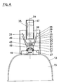
- einen Axialschnitt durch eine Hängeleuchte gemäß einer zweiten Ausführungsform der Erfindung.
- In
Fig. 1 ist eine Hängeleuchte mit einem zylindrischen Gehäuse 11 aus Edelstahl dargestellt, an dessen unterem Ende ein topfförmiger Reflektor 13 anschließt, der einen Aufnahmeraum 15 für ein nicht dargestelltes Leuchtmittel bildet und der über eine separat ausgebildete Bodenplatte 17 an dem Gehäuse 11 gehaltert ist. Durch das Zentrum der Bodenplatte 17 hindurch erstreckt sich eine Leuchtmittelfassung 19, die in den Aufnahmeraum 15 hineinreicht und in die das Leuchtmittel für die Leuchte, beispielsweise eine Hochdruck-Gasentladungslampe, einschraubbar ist. - Die Leuchtmittelfassung 19 ist auf der dem Reflektor 13 gegenüberliegenden Seite der Bodenplatte 17 an einem gehäusefesten Trägerteil 55 gehaltert, an dem ein Luftleitteil 21 befestigt ist, das als U-förmiges Winkelblech ausgebildet ist. Die beiden sich bezüglich einer Gehäuseachse 31 (
Fig. 2 ) gegenüberliegenden Schenkelflächen des Winkelblechs bilden jeweils eine im Wesentlichen ebene Luftleitwandung 23 und sind über eine sich parallel zu der Bodenplatte 17 erstreckende Basiswand 51 miteinander verbunden. - Das Trägerteil 55 ist an der Unterseite der Basiswand 51 angeschweißt, hält die Leuchtmittelfassung 19 und ist ferner mit dem Gehäuse 11 verschraubt. Darüber hinaus sind an dem Trägerteil 55 zwei Bolzen befestigt, die sich in Richtung Reflektor 13 erstrecken und die zur Halterung der Bodenplatte 17 dienen.
- Die Luftleitwandungen 23 und die Basiswand 51 liegen mit ihren seitlichen Begrenzungskanten jeweils an der Innenwand des Gehäuses 11 an. Grundsätzlich ist es jedoch auch möglich, dass die Luftleitwandungen 23 und/oder die Basiswand 51 geringfügig von der Innenwand des Gehäuses 11 beabstandet angeordnet sind.
- Die Luftleitwandungen 23 erstrecken sich unter einem spitzen Winkel zur Gehäuseachse 31 schräg nach oben und sind nach außen zum Gehäuse 11 hin geneigt, so dass zwischen den Luftleitwandungen 23 und dem Gehäuse 11 sich verjüngende Strömungskanäle 25 gebildet sind. Der Querschnitt der Strömungskanäle 25 ist dabei entlang der Gehäuseachse 31 in Strömungsrichtung jeweils um mehr als 50% reduziert. Die beiden Strömungskanäle 25 können an ihren unteren Enden, d.h. im Bereich der Bodenplatte 17 bzw. der Basiswand 51, strömungstechnisch miteinander verbunden oder aber auch voneinander getrennt sein.
- Die Bodenplatte 17 weist im Bereich der Strömungskanäle 25 jeweils eine Gruppe von Lufteintrittsschlitzen 27 auf (
Fig. 2 ), durch die die Strömungskanäle 25 jeweils an den Aufnahmeraum 15 für das Leuchtmittel strömungstechnisch angeschlossen sind. An ihrem oberen Ende gehen die Strömungskanäle 25 jeweils in eine Luftaustrittsöffnung 29 über (Fig. 3 ). Die jeweilige Luftaustrittsöffnung 29 wird dabei von dem Ende der jeweiligen Luftleitwandung 23 und der der jeweiligen Luftleitwandung 23 gegenüberliegenden Gehäusewandung begrenzt. - Zwischen den beiden Strömungskanälen 25 ist ein innerhalb des Gehäuses 11 liegender Freiraum 33 vorgesehen, in den mit Abstand zu den beiden Luftleitwandungen 23 ein insbesondere flachquaderförmiges Vorschaltgerät 35 für eine Hochdruck-Gasentladungslampe aufgenommen ist. Das Vorschaltgerät 35 ist hierzu in einem Behältnis 47 untergebracht. Das Behältnis 47 taucht dabei nur teilweise in den Freiraum 33 ein. Außerdem steht das Behältnis 47 mit seinen beiden seitlichen Enden radial über das Gehäuse 11 hinaus. Dies wird durch zwei diametral gegenüberliegende, in dem Gehäuse 11 ausgebildete Ausnehmungen ermöglicht, in die das Behältnis 47 berührungslos eingreift. Bei weiterer Miniaturisierung kann auch ein Behältnis Verwendung finden, das insgesamt innerhalb des Gehäuses Platz findet.
- Das Luftleitteil 21 ist über zwei Tragelemente 49, von denen in
Fig. 1 nur eines erkennbar ist, mit dem Behältnis 47, über das die Aufhängung der Hängeleuchte erfolgt kann, verbunden. Ein jedes der beiden Tragelemente 49 ist als Gewinderohr ausgebildet, auf das eine Distanzhülse aufgeschoben ist, die sich zwischen dem Behältnis 47 und der Basiswand 51 erstreckt, wobei die Fixierung des Behältnisses 47 und des Luftleitteils 21 aneinander über auf die Enden des Gewinderohrs aufgeschraubte Muttern erfolgt. Innerhalb wenigstens eines der Gewinderohre verlaufen die elektrischen Zuleitungen für das Leuchtmittel. - Die vorstehend anhand der
Fig. 1 bis 3 beschriebene Hängeleuchte ist zumindest im Wesentlichen spiegelsymmetrisch ausgebildet. - Im Betrieb steigt durch das Leuchtmittel in dem Aufnahmeraum 15 des Reflektors 13 erhitzte Luft aufgrund des sich dort bildenden Warmluftstaus durch die Lufteintrittsschlitze 27 in die beiden Strömungskanäle 25. Dort strömt die erhitzte Luft aufgrund des sich nach oben verjüngenden Querschnitts der beiden Strömungskanäle 25 beschleunigt weiter, um die beiden Strömungskanäle 25 durch die beiderseits des Vorschaltgeräts 35 und zu diesem beabstandet angeordneten Luftaustrittsöffnungen 29 wieder zu verlassen. Da die erhitzte Luft aufgrund ihrer Geschwindigkeit einen geringen statischen Druck aufweist, kommt es außerdem zu einer raschen Durchmischung mit kühlerer Umgebungsluft und entsprechender Luftabführung. Da die Luftleitwandungen 23 und die Basiswand 51 an der Innenwand des Gehäuses 11 anliegen oder nur wenig von dieser beabstandet angeordnet sind, dringt keine oder kaum erhitzte Luft in den Freiraum 33 vor, in dem das Vorschaltgerät 35 aufgenommen ist.
- Durch den vorstehend erläuterten Aufbau wird das Vorschaltgerät 35 optimal vor störender Erwärmung geschützt.
- Bei der Hängeleuchte gemäß
Fig. 4 ist neben dem Luftleitteil 21, das zur Ausbildung der Strömungskanäle 25 verwendet wird, die als eine erste Kühlstufe angesehen werden können, ein weiteres Luftleitteil 37 mit zwei Schenkelflächen oder Luftleitwandungen 39 und einer Basiswand 53 vorgesehen. Das weitere Luftleitteil 37 ist zumindest im Wesentlichen identisch zu dem Luftleitteil 21 ausgebildet und diesem in Strömungsrichtung beabstandet nachgeordnet. Auch die Luftleitwandungen 39 und die Basiswand 53 des weiteren Luftleitteils 37 liegen mit ihren seitlichen Begrenzungskanten an der Gehäuseinnenwand an oder können geringfügig von der Gehäuseinnenwand beabstandet angeordnet sein. - Hierdurch werden zwischen dem das Vorschaltgerät 35 aufnehmenden Behältnis 47 und den Strömungskanälen 25 durch das erste Luftleitteil 21 und das weitere Luftleitteil 37 zwei einander diametral gegenüberliegende Kaltluftkanäle 41 geschaffen. Die Kaltluftkanäle 41 stellen eine zweite Kühlstufe dar, die der ersten Kühlstufe kaskadenartig nachgeschaltet ist.
- Die Kaltluftkanäle 41 teilen sich in dem Gehäuse 11 ausgebildete Kaltlufteintrittsschlitze 43, die in
Fig. 4 in Form von gestrichelt gezeichneten Linien erkennbar sind. Die beiden Kaltluftkanäle 41 sind an ihren unteren Enden im Bereich des zwischen der Basiswand 51 und der Basiswand 53 befindlichen Kaltlufteintrittsraums miteinander verbunden. Grundsätzlich ist jedoch auch denkbar, dass für jeden der beiden Kaltluftkanäle 41 wenigstens ein eigener Kaltlufteintrittsschlitz vorgesehen ist und die beiden Kaltluftkanäle 41 strömungstechnisch voneinander getrennt sind. - Die Lufteintrittsschlitze 27 der Strömungskanäle 25 sind in der Ansicht in
Fig. 4 beiderseits der Gehäuseachse 31 angeordnet. Die Kaltlufteintrittsschlitze 43 der Kaltluftkanäle 41 sind in der Ansicht inFig. 4 vor der Gehäuseachse 31 angeordnet. Die Lufteintrittsschlitze 27 sind daher in Umfangsrichtung des Gehäuses 11 gegenüber den Kaltlufteintrittsschlitzen 43 jeweils um 90° versetzt. - Ferner weisen die Kaltluftkanäle 41 jeweils eine Kaltluftaustrittsöffnung 45 auf, die im Ausströmbereich des jeweils zugeordneten Strömungskanals 25 liegen. Die Kaltluftaustrittsöffnung 45 eines jeden Kaltluftkanals 41 ist dabei von dem Ende der Luftleitwandung 23 des zugehörigen Strömungskanals 25 und dem Ende der weiteren Luftleitwandung 39 des Kaltluftkanals 41 begrenzt. Der gegenseitige Abstand der Enden der Luftleitwandungen 23, 39 von Strömungskanal 25 und Kaltluftkanal 41 in Strömungsrichtung ist größer als der Abstand zwischen den Luftleitwandungen 23, 39 der Kanäle 29, 41 in Richtung einer Normalen zu den Luftleitwandungen 23, 39.
- Im Gegensatz zu der Hängeleuchte gemäß den
Fig. 1 bis 3 findet bei der Hängeleuchte gemäßFig. 4 zusätzlich eine Kaltluftansaugung statt. Die Kaltluft wird von der in den Strömungskanälen 25 aufsteigenden erhitzten Luft nach Art einer Venturi-Düse oder Wasserstrahlpumpe dabei von außerhalb des Gehäuses 11 durch die Kaltlufteintrittsschlitze 43 und durch die Kaltluftkanäle 41 hindurch angesaugt, um im Ausströmbereich der Strömungskanäle 25 mit der erhitzten Luft aus den Strömungskanälen 25 vermischt zu werden. Dabei schaffen die Kaltluftkanäle 41 eine Barriere aus kalter Luft, die eine Wärmeübertragung von der durch die Strömungskanäle 25 strömenden erhitzten Luft an das Vorschaltgerät 35 effektiv verhindert. - Durch den weitergebildeten Aufbau gemäß
Fig. 4 kann das Vorschaltgerät 35 noch besser vor übermäßiger Erwärmung geschützt werden. - Grundsätzlich ist es möglich, dass noch weitere Kühlstufen nach Art der zweiten Kühlstufe vorgesehen werden, wobei dann jede weitere Kühlstufe der jeweils vorhergehenden Kühlstufe entsprechend der vorstehend beschriebenen Art nachgeschaltet ist. Dies ist insbesondere bei weiter steigender Leistung der Leuchtmittel und einem damit verbundenen erhöhten Bedarf an Kühlung bzw. Wärmeabfuhr vorteilhaft.
-
- 11
- Gehäuse
- 13
- Reflektor
- 15
- Aufnahmeraum für ein Leuchtmittel
- 17
- Boden
- 19
- Leuchtmittelfassung
- 21
- Luftleitteil
- 23
- Luftleitwandung
- 25
- Strömungskanal
- 27
- Lufteintrittsschlitz
- 29
- Luftaustrittsöffnung
- 31
- Gehäuseachse
- 33
- Freiraum
- 35
- Vorschaltgerät
- 37
- weiteres Luftleitteil
- 39
- weitere Luftleitwandung
- 41
- Kaltluftkanal
- 43
- Kaltlufteintrittsschlitz
- 45
- Kaltluftaustrittsöffnung
- 47
- Behältnis
- 49
- Tragelement
- 51
- Basiswand
- 53
- weitere Basiswand
- 55
- Trägerteil
Claims (15)
- Leuchte, insbesondere Hängeleuchte, mit einem einen Aufnahmeraum (15) für ein Leuchtmittel bildenden Reflektor (13), einem Bodenteil (17) und einem sich bodenseitig an den Reflektor (13) anschließenden Gehäuse (11),
dadurch gekennzeichnet,
dass zumindest zum Teil in das Gehäuse (11) eingreifend ein elektronische Komponenten, insbesondere ein Vorschaltgerät (35) aufnehmendes Behältnis (47) und wenigstens eine das Behältnis (47) gegen störende Wärmeeinwirkung abschirmende Luftleitwandung (23) derart vorgesehen sind, dass zwischen dem Gehäuse (11) und der Luftleitwandung (23) ein sich in Richtung einer Luftaustrittsöffnung (29) verjüngender Strömungskanal (25) gebildet ist, der über zumindest eine im Bodenteil (17) ausgebildete Lufteintrittsöffnung (27) in Strömungsverbindung mit dem Aufnahmeraum (15) steht. - Leuchte nach Anspruch 1,
dadurch gekennzeichnet,
dass in dem Gehäuse (11) zwei derartige, sich diametral gegenüberliegende Luftleitwandungen (23) vorgesehen sind, und dass das Behältnis (47) in dem Freiraum (33) zwischen und mit Abstand zu den beiden divergierenden Luftleitwandungen (23) gehaltert ist. - Leuchte nach Anspruch 2,
dadurch gekennzeichnet,
dass die Luftleitwandungen (23) von den beiden Schenkelflächen eines in einem Axialschnitt zumindest im Wesentlichen U- oder V-förmigen Luftleitteils (21), insbesondere eines Winkelblechs, gebildet werden, wobei die seitlichen Begrenzungskanten dieser Schenkelflächen eng benachbart der Gehäuseinnenwand enden oder an dieser zumindest bereichsweise anliegen. - Leuchte nach Anspruch 3,
dadurch gekennzeichnet,
dass das Behältnis (47) über wenigstens ein Tragelement (49) an einer die beiden Schenkelflächen (23) verbindenden Basiswand (51) fixiert ist, wobei bevorzugt das Tragelement (49) von einem gleichzeitig zur Leitungsführung dienenden Rohrstutzen gebildet ist. - Leuchte nach einem der Ansprüche 3 oder 4,
dadurch gekennzeichnet,
dass mit dem Luftleitteil (21) wenigstens ein am Gehäuse (11) befestigtes Trägerteil (55) verbunden ist. - Leuchte nach Anspruch 5,
dadurch gekennzeichnet,
dass das Trägerteil (55) zur Halterung einer das Bodenteil (17) durchsetzenden Leuchtmittelfassung (19) ausgebildet ist. - Leuchte nach einem der vorstehenden Ansprüche,
dadurch gekennzeichnet,
dass zur Ausbildung des sich verjüngenden Strömungskanals (25) die insbesondere ebene Luftleitwandung (23) unter einem spitzen Winkel zur Gehäuseachse (31) zum insbesondere zylinderförmigen Gehäuse (11) hin geneigt ist. - Leuchte nach einem der vorstehenden Ansprüche,
dadurch gekennzeichnet,
dass die Querschnittsreduzierung des Strömungskanals (25) in Strömungsrichtung wenigstens 50% beträgt. - Leuchte nach einem der vorstehenden Ansprüche,
dadurch gekennzeichnet,
dass zwischen jedem Strömungskanal (25) und dem die Elektronikkomponenten aufnehmenden Behältnis (47) zumindest ein Kaltluftkanal (41) vorgesehen ist, dessen wenigstens eine Eintrittsöffnung (43) in der Gehäusewandung ausgebildet und dessen Austrittsöffnung (45) im Ausströmbereich der eine Saugwirkung im Kaltluftkanal (41) bewirkenden erhitzten Luft des zugeordneten Strömungskanals (25) gelegen ist. - Leuchte nach Anspruch 9,
dadurch gekennzeichnet,
dass jeder Kaltluftkanal (41) von der dem Strömungskanal (25) zugeordneten Luftleitwandung (23) und einer dazu beabstandeten und zumindest im Wesentlichen dazu parallelen weiteren Luftleitwandung (39) gebildet ist. - Leuchte nach Anspruch 10, dadurch gekennzeichnet,
dass die Luftaustrittsöffnung (29) des Strömungskanals (25) von dem Ende der zugeordneten Luftleitwandung (23) und der dieser gegenüberliegenden Gehäusewandung und die Kaltluftaustrittsöffnung (45) von den Enden der Luftleitwandungen (23, 39) von Strömungskanal (25) und Kaltluftkanal (41) begrenzt ist. - Leuchte nach Anspruch 11, dadurch gekennzeichnet,
dass der gegenseitige vertikale Abstand der Enden der Luftleitwandungen (23, 39) von Strömungskanal (25) und Kaltluftkanal (41) größer ist als der Normalenabstand zwischen den Luftleitwandungen (23, 39) der Kanäle (25, 41). - Leuchte nach einem der Ansprüche 9 bis 12,
dadurch gekennzeichnet,
dass die Kaltlufteintrittsöffnung (43) und die Lufteintrittsöffnung (27) des Strömungskanals (25) in Umfangsrichtung des Gehäuses (11) gegeneinander versetzt sind. - Leuchte nach einem der vorstehenden Ansprüche,
dadurch gekennzeichnet,
dass das Bodenteil (17) als ein von dem Reflektor (13) separates Teil und als Reflektorhalter ausgebildet ist. - Leuchte nach einem der vorstehenden Ansprüche,
dadurch gekennzeichnet,
dass das Behältnis (47) berührungsfrei in Ausnehmungen des Gehäuses (11) eingreift und sich über das Gehäuse (11) hinaus erstreckt.
Applications Claiming Priority (1)
| Application Number | Priority Date | Filing Date | Title |
|---|---|---|---|
| DE102008006535A DE102008006535A1 (de) | 2008-01-29 | 2008-01-29 | Leuchte |
Publications (2)
| Publication Number | Publication Date |
|---|---|
| EP2085691A1 true EP2085691A1 (de) | 2009-08-05 |
| EP2085691B1 EP2085691B1 (de) | 2011-08-31 |
Family
ID=40578182
Family Applications (1)
| Application Number | Title | Priority Date | Filing Date |
|---|---|---|---|
| EP09000529A Not-in-force EP2085691B1 (de) | 2008-01-29 | 2009-01-15 | Leuchte |
Country Status (3)
| Country | Link |
|---|---|
| EP (1) | EP2085691B1 (de) |
| AT (1) | ATE522770T1 (de) |
| DE (1) | DE102008006535A1 (de) |
Families Citing this family (1)
| Publication number | Priority date | Publication date | Assignee | Title |
|---|---|---|---|---|
| DE102012222184B4 (de) | 2012-12-04 | 2025-08-14 | Zumtobel Lighting Gmbh | Leuchte mit Luftleitflächen |
Citations (2)
| Publication number | Priority date | Publication date | Assignee | Title |
|---|---|---|---|---|
| WO2004018934A1 (en) | 2002-08-22 | 2004-03-04 | Ian Thomas Craig | A down light protector arrangement |
| US20060232984A1 (en) | 2005-03-08 | 2006-10-19 | Kory Schuknecht | Compact fluorescent lamp fixture ventilation method and apparatus |
Family Cites Families (3)
| Publication number | Priority date | Publication date | Assignee | Title |
|---|---|---|---|---|
| DE8710698U1 (de) * | 1987-08-05 | 1987-09-17 | Korsch, Alfred, 4154 Tönisvorst | Leuchte |
| DE29505278U1 (de) * | 1995-03-30 | 1995-05-24 | Rhönmetall GmbH, 36466 Dermbach | Vorrichtung zur Beleuchtung von Warenauslagen für Eßwaren sowie zur Luftzuführung |
| DE20202558U1 (de) * | 2002-02-19 | 2003-07-03 | Zumtobel Staff GmbH & Co. KG, 32657 Lemgo | Konvektionsreflektor |
-
2008
- 2008-01-29 DE DE102008006535A patent/DE102008006535A1/de not_active Withdrawn
-
2009
- 2009-01-15 EP EP09000529A patent/EP2085691B1/de not_active Not-in-force
- 2009-01-15 AT AT09000529T patent/ATE522770T1/de active
Patent Citations (2)
| Publication number | Priority date | Publication date | Assignee | Title |
|---|---|---|---|---|
| WO2004018934A1 (en) | 2002-08-22 | 2004-03-04 | Ian Thomas Craig | A down light protector arrangement |
| US20060232984A1 (en) | 2005-03-08 | 2006-10-19 | Kory Schuknecht | Compact fluorescent lamp fixture ventilation method and apparatus |
Also Published As
| Publication number | Publication date |
|---|---|
| EP2085691B1 (de) | 2011-08-31 |
| ATE522770T1 (de) | 2011-09-15 |
| DE102008006535A1 (de) | 2009-07-30 |
Similar Documents
| Publication | Publication Date | Title |
|---|---|---|
| EP1461979B1 (de) | Lampe | |
| EP2404110B1 (de) | Beleuchtungsvorrichtung mit mindestens einem kühlkörper | |
| DE102010034996B4 (de) | Leuchtengehäuse | |
| EP2929237A1 (de) | Leuchte mit luftleitflächen | |
| DE202007005003U1 (de) | Leuchte, insbesondere Gefahrenfeuer für Windkraftanlagen | |
| EP2622261B1 (de) | Anordnung zur lichtabgabe | |
| EP0415076A2 (de) | Schmutzsauger | |
| EP2743564B2 (de) | Beleuchtungseinrichtung und Beleuchtungsanordnung zum Beleuchten des Innenraumes eines Turmes oder Tunnels | |
| DE202015100867U1 (de) | Leuchtenanordnung | |
| EP2647907B1 (de) | Leuchteneinsatz mit reflektor | |
| EP2012057B1 (de) | Leuchte | |
| EP2085691B1 (de) | Leuchte | |
| EP2129965B1 (de) | Lampenanordnung mit kühleinrichtung | |
| EP2525137A1 (de) | Leuchte mit einem LED-Modul als Leuchtmittel und einem Gebläse zur Kühlung | |
| CH704544A1 (de) | Leuchteinrichtung mit Wärmeverteiler. | |
| DE102024128942A1 (de) | Induktionskochfeld | |
| EP2426408B1 (de) | Flexible Beleuchtungsanordnung | |
| EP2256404A1 (de) | Anordnung zur Lichtabgabe mit Leuchtelementen | |
| DE102005045203B4 (de) | Modulare Bestrahlungsvorrichtung | |
| DE202017006973U1 (de) | Beleuchtungsvorrichtung | |
| DE102013107395B4 (de) | LED-Hochleistungsspot | |
| DE10257432B4 (de) | Luftgekühlte Bestrahlungsanordnung | |
| WO2020057986A1 (de) | Leuchte zum einbau in eine decke | |
| DE202012100848U1 (de) | LED-Leuchtmittel | |
| DE102005054031B4 (de) | Hochleistungsleuchte mit Kühlmantel |
Legal Events
| Date | Code | Title | Description |
|---|---|---|---|
| PUAI | Public reference made under article 153(3) epc to a published international application that has entered the european phase |
Free format text: ORIGINAL CODE: 0009012 |
|
| AK | Designated contracting states |
Kind code of ref document: A1 Designated state(s): AT BE BG CH CY CZ DE DK EE ES FI FR GB GR HR HU IE IS IT LI LT LU LV MC MK MT NL NO PL PT RO SE SI SK TR |
|
| AX | Request for extension of the european patent |
Extension state: AL BA RS |
|
| 17P | Request for examination filed |
Effective date: 20091016 |
|
| AKX | Designation fees paid |
Designated state(s): AT BE BG CH CY CZ DE DK EE ES FI FR GB GR HR HU IE IS IT LI LT LU LV MC MK MT NL NO PL PT RO SE SI SK TR |
|
| 17Q | First examination report despatched |
Effective date: 20100806 |
|
| GRAP | Despatch of communication of intention to grant a patent |
Free format text: ORIGINAL CODE: EPIDOSNIGR1 |
|
| GRAS | Grant fee paid |
Free format text: ORIGINAL CODE: EPIDOSNIGR3 |
|
| GRAA | (expected) grant |
Free format text: ORIGINAL CODE: 0009210 |
|
| AK | Designated contracting states |
Kind code of ref document: B1 Designated state(s): AT BE BG CH CY CZ DE DK EE ES FI FR GB GR HR HU IE IS IT LI LT LU LV MC MK MT NL NO PL PT RO SE SI SK TR |
|
| REG | Reference to a national code |
Ref country code: CH Ref legal event code: EP Ref country code: GB Ref legal event code: FG4D Free format text: NOT ENGLISH |
|
| REG | Reference to a national code |
Ref country code: IE Ref legal event code: FG4D Free format text: LANGUAGE OF EP DOCUMENT: GERMAN |
|
| REG | Reference to a national code |
Ref country code: DE Ref legal event code: R096 Ref document number: 502009001206 Country of ref document: DE Effective date: 20111103 |
|
| REG | Reference to a national code |
Ref country code: NL Ref legal event code: VDEP Effective date: 20110831 |
|
| LTIE | Lt: invalidation of european patent or patent extension |
Effective date: 20110831 |
|
| REG | Reference to a national code |
Ref country code: DE Ref legal event code: R082 Ref document number: 502009001206 Country of ref document: DE Representative=s name: , |
|
| PG25 | Lapsed in a contracting state [announced via postgrant information from national office to epo] |
Ref country code: HR Free format text: LAPSE BECAUSE OF FAILURE TO SUBMIT A TRANSLATION OF THE DESCRIPTION OR TO PAY THE FEE WITHIN THE PRESCRIBED TIME-LIMIT Effective date: 20110831 Ref country code: FI Free format text: LAPSE BECAUSE OF FAILURE TO SUBMIT A TRANSLATION OF THE DESCRIPTION OR TO PAY THE FEE WITHIN THE PRESCRIBED TIME-LIMIT Effective date: 20110831 Ref country code: SE Free format text: LAPSE BECAUSE OF FAILURE TO SUBMIT A TRANSLATION OF THE DESCRIPTION OR TO PAY THE FEE WITHIN THE PRESCRIBED TIME-LIMIT Effective date: 20110831 Ref country code: NL Free format text: LAPSE BECAUSE OF FAILURE TO SUBMIT A TRANSLATION OF THE DESCRIPTION OR TO PAY THE FEE WITHIN THE PRESCRIBED TIME-LIMIT Effective date: 20110831 Ref country code: NO Free format text: LAPSE BECAUSE OF FAILURE TO SUBMIT A TRANSLATION OF THE DESCRIPTION OR TO PAY THE FEE WITHIN THE PRESCRIBED TIME-LIMIT Effective date: 20111130 Ref country code: IS Free format text: LAPSE BECAUSE OF FAILURE TO SUBMIT A TRANSLATION OF THE DESCRIPTION OR TO PAY THE FEE WITHIN THE PRESCRIBED TIME-LIMIT Effective date: 20111231 Ref country code: LT Free format text: LAPSE BECAUSE OF FAILURE TO SUBMIT A TRANSLATION OF THE DESCRIPTION OR TO PAY THE FEE WITHIN THE PRESCRIBED TIME-LIMIT Effective date: 20110831 |
|
| PG25 | Lapsed in a contracting state [announced via postgrant information from national office to epo] |
Ref country code: SI Free format text: LAPSE BECAUSE OF FAILURE TO SUBMIT A TRANSLATION OF THE DESCRIPTION OR TO PAY THE FEE WITHIN THE PRESCRIBED TIME-LIMIT Effective date: 20110831 Ref country code: LV Free format text: LAPSE BECAUSE OF FAILURE TO SUBMIT A TRANSLATION OF THE DESCRIPTION OR TO PAY THE FEE WITHIN THE PRESCRIBED TIME-LIMIT Effective date: 20110831 Ref country code: CY Free format text: LAPSE BECAUSE OF FAILURE TO SUBMIT A TRANSLATION OF THE DESCRIPTION OR TO PAY THE FEE WITHIN THE PRESCRIBED TIME-LIMIT Effective date: 20110831 Ref country code: GR Free format text: LAPSE BECAUSE OF FAILURE TO SUBMIT A TRANSLATION OF THE DESCRIPTION OR TO PAY THE FEE WITHIN THE PRESCRIBED TIME-LIMIT Effective date: 20111201 |
|
| REG | Reference to a national code |
Ref country code: DE Ref legal event code: R081 Ref document number: 502009001206 Country of ref document: DE Owner name: OSRAM GMBH, DE Free format text: FORMER OWNER: MED LICHT GMBH, 31162 BAD SALZDETFURTH, DE Effective date: 20120126 Ref country code: DE Ref legal event code: R081 Ref document number: 502009001206 Country of ref document: DE Owner name: OSRAM AG, DE Free format text: FORMER OWNER: MED LICHT GMBH, 31162 BAD SALZDETFURTH, DE Effective date: 20120126 |
|
| REG | Reference to a national code |
Ref country code: IE Ref legal event code: FD4D |
|
| RAP2 | Party data changed (patent owner data changed or rights of a patent transferred) |
Owner name: OSRAM AG |
|
| PG25 | Lapsed in a contracting state [announced via postgrant information from national office to epo] |
Ref country code: CZ Free format text: LAPSE BECAUSE OF FAILURE TO SUBMIT A TRANSLATION OF THE DESCRIPTION OR TO PAY THE FEE WITHIN THE PRESCRIBED TIME-LIMIT Effective date: 20110831 Ref country code: IE Free format text: LAPSE BECAUSE OF FAILURE TO SUBMIT A TRANSLATION OF THE DESCRIPTION OR TO PAY THE FEE WITHIN THE PRESCRIBED TIME-LIMIT Effective date: 20110831 Ref country code: SK Free format text: LAPSE BECAUSE OF FAILURE TO SUBMIT A TRANSLATION OF THE DESCRIPTION OR TO PAY THE FEE WITHIN THE PRESCRIBED TIME-LIMIT Effective date: 20110831 |
|
| REG | Reference to a national code |
Ref country code: GB Ref legal event code: 732E Free format text: REGISTERED BETWEEN 20120419 AND 20120425 |
|
| PG25 | Lapsed in a contracting state [announced via postgrant information from national office to epo] |
Ref country code: IT Free format text: LAPSE BECAUSE OF FAILURE TO SUBMIT A TRANSLATION OF THE DESCRIPTION OR TO PAY THE FEE WITHIN THE PRESCRIBED TIME-LIMIT Effective date: 20110831 Ref country code: EE Free format text: LAPSE BECAUSE OF FAILURE TO SUBMIT A TRANSLATION OF THE DESCRIPTION OR TO PAY THE FEE WITHIN THE PRESCRIBED TIME-LIMIT Effective date: 20110831 Ref country code: PL Free format text: LAPSE BECAUSE OF FAILURE TO SUBMIT A TRANSLATION OF THE DESCRIPTION OR TO PAY THE FEE WITHIN THE PRESCRIBED TIME-LIMIT Effective date: 20110831 Ref country code: RO Free format text: LAPSE BECAUSE OF FAILURE TO SUBMIT A TRANSLATION OF THE DESCRIPTION OR TO PAY THE FEE WITHIN THE PRESCRIBED TIME-LIMIT Effective date: 20110831 Ref country code: PT Free format text: LAPSE BECAUSE OF FAILURE TO SUBMIT A TRANSLATION OF THE DESCRIPTION OR TO PAY THE FEE WITHIN THE PRESCRIBED TIME-LIMIT Effective date: 20120102 |
|
| REG | Reference to a national code |
Ref country code: FR Ref legal event code: TP Owner name: OSRAM AG, DE Effective date: 20120522 |
|
| PG25 | Lapsed in a contracting state [announced via postgrant information from national office to epo] |
Ref country code: DK Free format text: LAPSE BECAUSE OF FAILURE TO SUBMIT A TRANSLATION OF THE DESCRIPTION OR TO PAY THE FEE WITHIN THE PRESCRIBED TIME-LIMIT Effective date: 20110831 |
|
| PLBE | No opposition filed within time limit |
Free format text: ORIGINAL CODE: 0009261 |
|
| STAA | Information on the status of an ep patent application or granted ep patent |
Free format text: STATUS: NO OPPOSITION FILED WITHIN TIME LIMIT |
|
| BERE | Be: lapsed |
Owner name: MED LICHT G.M.B.H. Effective date: 20120131 |
|
| 26N | No opposition filed |
Effective date: 20120601 |
|
| PG25 | Lapsed in a contracting state [announced via postgrant information from national office to epo] |
Ref country code: MC Free format text: LAPSE BECAUSE OF NON-PAYMENT OF DUE FEES Effective date: 20120131 |
|
| REG | Reference to a national code |
Ref country code: DE Ref legal event code: R097 Ref document number: 502009001206 Country of ref document: DE Effective date: 20120601 |
|
| PG25 | Lapsed in a contracting state [announced via postgrant information from national office to epo] |
Ref country code: BE Free format text: LAPSE BECAUSE OF NON-PAYMENT OF DUE FEES Effective date: 20120131 |
|
| PG25 | Lapsed in a contracting state [announced via postgrant information from national office to epo] |
Ref country code: MK Free format text: LAPSE BECAUSE OF FAILURE TO SUBMIT A TRANSLATION OF THE DESCRIPTION OR TO PAY THE FEE WITHIN THE PRESCRIBED TIME-LIMIT Effective date: 20110831 |
|
| REG | Reference to a national code |
Ref country code: DE Ref legal event code: R081 Ref document number: 502009001206 Country of ref document: DE Owner name: OSRAM GMBH, DE Free format text: FORMER OWNER: OSRAM AG, 81543 MUENCHEN, DE Effective date: 20130205 |
|
| PG25 | Lapsed in a contracting state [announced via postgrant information from national office to epo] |
Ref country code: ES Free format text: LAPSE BECAUSE OF FAILURE TO SUBMIT A TRANSLATION OF THE DESCRIPTION OR TO PAY THE FEE WITHIN THE PRESCRIBED TIME-LIMIT Effective date: 20111211 |
|
| PG25 | Lapsed in a contracting state [announced via postgrant information from national office to epo] |
Ref country code: BG Free format text: LAPSE BECAUSE OF FAILURE TO SUBMIT A TRANSLATION OF THE DESCRIPTION OR TO PAY THE FEE WITHIN THE PRESCRIBED TIME-LIMIT Effective date: 20111130 |
|
| PG25 | Lapsed in a contracting state [announced via postgrant information from national office to epo] |
Ref country code: MT Free format text: LAPSE BECAUSE OF FAILURE TO SUBMIT A TRANSLATION OF THE DESCRIPTION OR TO PAY THE FEE WITHIN THE PRESCRIBED TIME-LIMIT Effective date: 20110831 |
|
| REG | Reference to a national code |
Ref country code: CH Ref legal event code: PL |
|
| REG | Reference to a national code |
Ref country code: DE Ref legal event code: R081 Ref document number: 502009001206 Country of ref document: DE Owner name: OSRAM GMBH, DE Free format text: FORMER OWNER: OSRAM GMBH, 81543 MUENCHEN, DE Effective date: 20130823 |
|
| PG25 | Lapsed in a contracting state [announced via postgrant information from national office to epo] |
Ref country code: LI Free format text: LAPSE BECAUSE OF NON-PAYMENT OF DUE FEES Effective date: 20130131 Ref country code: CH Free format text: LAPSE BECAUSE OF NON-PAYMENT OF DUE FEES Effective date: 20130131 |
|
| PG25 | Lapsed in a contracting state [announced via postgrant information from national office to epo] |
Ref country code: TR Free format text: LAPSE BECAUSE OF FAILURE TO SUBMIT A TRANSLATION OF THE DESCRIPTION OR TO PAY THE FEE WITHIN THE PRESCRIBED TIME-LIMIT Effective date: 20110831 |
|
| PG25 | Lapsed in a contracting state [announced via postgrant information from national office to epo] |
Ref country code: LU Free format text: LAPSE BECAUSE OF NON-PAYMENT OF DUE FEES Effective date: 20120115 |
|
| PG25 | Lapsed in a contracting state [announced via postgrant information from national office to epo] |
Ref country code: HU Free format text: LAPSE BECAUSE OF FAILURE TO SUBMIT A TRANSLATION OF THE DESCRIPTION OR TO PAY THE FEE WITHIN THE PRESCRIBED TIME-LIMIT Effective date: 20090115 |
|
| REG | Reference to a national code |
Ref country code: AT Ref legal event code: MM01 Ref document number: 522770 Country of ref document: AT Kind code of ref document: T Effective date: 20140115 |
|
| PG25 | Lapsed in a contracting state [announced via postgrant information from national office to epo] |
Ref country code: AT Free format text: LAPSE BECAUSE OF NON-PAYMENT OF DUE FEES Effective date: 20140115 |
|
| REG | Reference to a national code |
Ref country code: FR Ref legal event code: PLFP Year of fee payment: 8 |
|
| REG | Reference to a national code |
Ref country code: FR Ref legal event code: PLFP Year of fee payment: 9 |
|
| REG | Reference to a national code |
Ref country code: FR Ref legal event code: PLFP Year of fee payment: 10 |
|
| PGFP | Annual fee paid to national office [announced via postgrant information from national office to epo] |
Ref country code: DE Payment date: 20180122 Year of fee payment: 10 Ref country code: GB Payment date: 20180119 Year of fee payment: 10 |
|
| PGFP | Annual fee paid to national office [announced via postgrant information from national office to epo] |
Ref country code: FR Payment date: 20180119 Year of fee payment: 10 |
|
| REG | Reference to a national code |
Ref country code: DE Ref legal event code: R119 Ref document number: 502009001206 Country of ref document: DE |
|
| GBPC | Gb: european patent ceased through non-payment of renewal fee |
Effective date: 20190115 |
|
| PG25 | Lapsed in a contracting state [announced via postgrant information from national office to epo] |
Ref country code: DE Free format text: LAPSE BECAUSE OF NON-PAYMENT OF DUE FEES Effective date: 20190801 Ref country code: FR Free format text: LAPSE BECAUSE OF NON-PAYMENT OF DUE FEES Effective date: 20190131 |
|
| PG25 | Lapsed in a contracting state [announced via postgrant information from national office to epo] |
Ref country code: GB Free format text: LAPSE BECAUSE OF NON-PAYMENT OF DUE FEES Effective date: 20190115 |