EP2085543A2 - Serrure - Google Patents
Serrure Download PDFInfo
- Publication number
- EP2085543A2 EP2085543A2 EP08019545A EP08019545A EP2085543A2 EP 2085543 A2 EP2085543 A2 EP 2085543A2 EP 08019545 A EP08019545 A EP 08019545A EP 08019545 A EP08019545 A EP 08019545A EP 2085543 A2 EP2085543 A2 EP 2085543A2
- Authority
- EP
- European Patent Office
- Prior art keywords
- lock
- actuator
- latch
- blocking element
- blocking
- Prior art date
- Legal status (The legal status is an assumption and is not a legal conclusion. Google has not performed a legal analysis and makes no representation as to the accuracy of the status listed.)
- Granted
Links
- 230000000903 blocking effect Effects 0.000 claims abstract description 84
- 230000036316 preload Effects 0.000 claims description 2
- 238000006073 displacement reaction Methods 0.000 description 7
- 230000008878 coupling Effects 0.000 description 5
- 238000010168 coupling process Methods 0.000 description 5
- 238000005859 coupling reaction Methods 0.000 description 5
- 230000007717 exclusion Effects 0.000 description 3
- 238000003780 insertion Methods 0.000 description 2
- 230000037431 insertion Effects 0.000 description 2
- 230000005540 biological transmission Effects 0.000 description 1
- 230000015572 biosynthetic process Effects 0.000 description 1
- 238000010276 construction Methods 0.000 description 1
- 230000000694 effects Effects 0.000 description 1
- 230000035515 penetration Effects 0.000 description 1
Images


Classifications
-
- E—FIXED CONSTRUCTIONS
- E05—LOCKS; KEYS; WINDOW OR DOOR FITTINGS; SAFES
- E05C—BOLTS OR FASTENING DEVICES FOR WINGS, SPECIALLY FOR DOORS OR WINDOWS
- E05C9/00—Arrangements of simultaneously actuated bolts or other securing devices at well-separated positions on the same wing
- E05C9/04—Arrangements of simultaneously actuated bolts or other securing devices at well-separated positions on the same wing with two sliding bars moved in opposite directions when fastening or unfastening
-
- E—FIXED CONSTRUCTIONS
- E05—LOCKS; KEYS; WINDOW OR DOOR FITTINGS; SAFES
- E05B—LOCKS; ACCESSORIES THEREFOR; HANDCUFFS
- E05B17/00—Accessories in connection with locks
- E05B17/0054—Fraction or shear lines; Slip-clutches, resilient parts or the like for preventing damage when forced or slammed
- E05B17/0058—Fraction or shear lines; Slip-clutches, resilient parts or the like for preventing damage when forced or slammed with non-destructive disengagement
-
- E—FIXED CONSTRUCTIONS
- E05—LOCKS; KEYS; WINDOW OR DOOR FITTINGS; SAFES
- E05B—LOCKS; ACCESSORIES THEREFOR; HANDCUFFS
- E05B17/00—Accessories in connection with locks
- E05B17/20—Means independent of the locking mechanism for preventing unauthorised opening, e.g. for securing the bolt in the fastening position
- E05B17/2007—Securing, deadlocking or "dogging" the bolt in the fastening position
- E05B17/2015—Securing, deadlocking or "dogging" the bolt in the fastening position with wedging action
-
- E—FIXED CONSTRUCTIONS
- E05—LOCKS; KEYS; WINDOW OR DOOR FITTINGS; SAFES
- E05B—LOCKS; ACCESSORIES THEREFOR; HANDCUFFS
- E05B17/00—Accessories in connection with locks
- E05B17/20—Means independent of the locking mechanism for preventing unauthorised opening, e.g. for securing the bolt in the fastening position
- E05B17/2007—Securing, deadlocking or "dogging" the bolt in the fastening position
- E05B17/203—Securing, deadlocking or "dogging" the bolt in the fastening position not following the movement of the bolt
- E05B17/2038—Securing, deadlocking or "dogging" the bolt in the fastening position not following the movement of the bolt moving rectilinearly
-
- E—FIXED CONSTRUCTIONS
- E05—LOCKS; KEYS; WINDOW OR DOOR FITTINGS; SAFES
- E05B—LOCKS; ACCESSORIES THEREFOR; HANDCUFFS
- E05B55/00—Locks in which a sliding latch is used also as a locking bolt
-
- E—FIXED CONSTRUCTIONS
- E05—LOCKS; KEYS; WINDOW OR DOOR FITTINGS; SAFES
- E05C—BOLTS OR FASTENING DEVICES FOR WINGS, SPECIALLY FOR DOORS OR WINDOWS
- E05C9/00—Arrangements of simultaneously actuated bolts or other securing devices at well-separated positions on the same wing
- E05C9/18—Details of fastening means or of fixed retaining means for the ends of bars
- E05C9/1825—Fastening means
- E05C9/1833—Fastening means performing sliding movements
- E05C9/1841—Fastening means performing sliding movements perpendicular to actuating bar
Definitions
- the present invention relates to a lock having a latch and an actuator operatively connected to each other such that the latch is movable from an extended position to a retracted position by operation of the actuator and vice versa when the latch is in an unlocked condition.
- a lock having a latch and an actuator operatively connected to each other such that the latch is movable from an extended position to a retracted position by operation of the actuator and vice versa when the latch is in an unlocked condition.
- an actuator by which the lock is switchable between the unlocked state and a locked state
- a blocking element operatively connected to the actuator, by which movement of the lock latch is prevented in the retracted position when the lock is in the locked state.
- Locks of this type are used in particular for doors, but can also be used in windows or the like. Furthermore, these locks can be both conventional one-latch locks and, for example, three-latch locks or the like, which usually comprise a so-called main lock and one or more secondary locks.
- the actuator is usually formed by a pusher, while in a secondary lock, the actuator may be formed for example by a part of a drive rod or coupled to thekulturstrange control member.
- the blocking element prevents the latch from being pressed back when the lock is in its locked state.
- the problem is, however, that the blocking element often can not develop its effect if the engaging in the strike plate lock latch before reaching its fully extended position already abuts the window or door frame and thus can not be fully extended. This case can occur, for example, if the existing in the lock catch area is not big enough. Since in this case the latch and the blocking element can not assume their predetermined position to each other, it is possible that the lock is not completely blocked and the blocking element can not be brought into its blocking effect ensuring position and thus the latch is not secured against pushing back.
- the blocking element comprises a blocking portion which engages when locking the lock in a free space, which partially defined by a provided on the latch or on an element connected to the lock element investment area
- the blocking section comprises an abutment section designed to abut against the abutment region, that the abutment section and the abutment region run obliquely relative to one another, and that at least one part of the blocking section encompassing part of the abutment section can also be inserted into the free space when the lock catch is between the abutment retracted and the extended position is located.
- the abutment portion and / or the abutment region are formed in stages with abutment surfaces formed for abutment against the abutment region or the abutment portion.
- only the contact section, only the contact area or both can be designed in stages.
- at least a portion of the step surfaces extend substantially parallel to the contact portion or the contact area, it is achieved that upon pushing back of the lock latch, the forces occurring are directed substantially perpendicular to the step surfaces and thus no blocking forces the blocking element from its blocking position force components occur.
- at least a part of the step surfaces can also run obliquely to the contact section or the contact region. As a result, or even by a complete unestimated, oblique formation, a substantially continuous contact of the contact section be achieved at the investment area at different intermediate positions of the latch.
- At least a part of the step surfaces are connected to each other by chamfers. Due to the run-on slopes, the lock catch is pushed even further into the extended position during movement of the blocking element, so that the lock catch may possibly assume its fully extended position or at least a further extended position.
- the blocking element is moved together with the actuator when the lock is switched with the lock bolt fully extended from the unlocked to the locked position or vice versa.
- fully extended latch latch thus the blocking element and the actuator are always moved together to achieve a reliable locking of the latch in the locked state and release of the latch in the unlocked state.
- the movement of the blocking element is preferably carried out substantially perpendicular to the direction of displacement of the latch or the element connected to the latch.
- the blocking element and the actuator are held together by a defined predetermined force, wherein upon overcoming the defined predetermined force, the blocking element and the actuator are movable relative to each other.
- the defined predetermined force can be generated for example by a spring preload, by a latching, by a clamping connection or by a frictional connection.
- the blocking element and the actuator are thus not fixed and undetachably connected to each other, but can be moved relative to each other, for example when the lock is locked when the latch is not fully extended, the contact section comes into contact with the contact area and further movement of the blocking element through this contact is prevented.
- the partially introduced into the free space blocking element remains in its position reached, while the actuator is moved in the position required for complete locking of the lock position.
- the blocking element and the actuator are thus in the unlocked position of the lock in a fully coupled position, while the blocking element and the actuator can be brought by the relative movement in a partially coupled position or in a mutually decoupled position.
- the blocking element and the actuator are automatically brought into the fully coupled position when the lock is unlocked.
- an end stop for the blocking element can be provided, by which a movement of the blocking element is limited when unlocking the lock.
- a spring element is provided by which the latch bolt is urged from the retracted position to the extended position.
- a spring element is provided, which acts on the actuator or a latch and actuator connecting gear member, and the latch is moved when moving back the actuator to its initial position by a corresponding mechanical coupling in the extended position.
- Fig. 1 shows a door 1 with a three-trap lock 2, which includes a main lock 3 and two secondary locks 4, which may be identical.
- the main lock 3 comprises a pusher 5, via which in the usual way a latch 6 of a in Fig. 1 shown extended position can be moved to a retracted position by the pusher 5 is pivoted about a pusher 7 down.
- the latch bolt 6 is moved in a known manner by spring force support again in the extended position.
- the movement of the pusher 5 is transmitted in each case via a drive rod 8 to the secondary locks 4, the lock latches 9 have.
- the lock latches 9 are coupled via the drive rods 8 with the pusher 5 so that it moves in parallel with the latch bolt 6, that can be changed between a retracted position and an extended position.
- the main lock 3 further comprises a lock cylinder 10, via which the three-latch lock 2 can be locked.
- a lock cylinder 10 via which the three-latch lock 2 can be locked.
- both the main lock 3 as also the secondary locks 4 locked.
- the lock traps 6, 9 are each arranged in the extended position and blocked against pushing back into the retracted position.
- locking bolt 12 or other locking elements may be provided.
- the control of the locking elements, that is the blocking of the lock latch 6, 9 and the extension of the locking bolt 12 and the rod exclusions 11 takes place in the usual way via locking bars 13 and provided within the main lock 3 and the secondary locks 4 lock transmission elements.
- the invention will be described in more detail with reference to an embodiment which show the construction of a secondary lock.
- the invention can also be applied analogously to a main lock.
- the main difference lies in the fact that in a main lock a lock cylinder is present, via which the locking of the main lock is made directly, while the secondary locks starting from the lock cylinder of the main lock the locking takes place respectively via the locking bars.
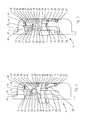
- a lock 14 according to the invention is shown in six different positions.
- the lock 14 has a lock housing 15, of which only a lock cover 16 is shown in the figures, which is located in the lowest level of the drawing plane.
- the lock cover 16 comprises on its longitudinal side a perpendicular to the plane of the lock cover extending portion which forms a rear wall 17 of the lock housing 15.
- a lock lid 16 corresponding, not shown in the figures, further counter lock cover provided, which can be connected to the lock cover 16 so that the individual subsequently described lock elements are arranged between the two lock covers.
- the lock catch 9 is arranged, which by two guide portions 18, 19, which are formed for example of characteristics in the lock cover 16, for moving according to a double arrow 20 of the in Fig. 2 illustrated fully extended position in the in Fig. 3 shown retracted position is performed.
- the guide portion 19 has at its rear end a 90 ° angled portion 21 which forms a rear end stop for the latch 9.
- a pin 22 is fixed, on which a trained as a spiral spring spring element 23 is attached. While a free end 24 of the spring element 23 is supported on the rear wall 17, the other free end 25 is formed longer and is located at a rear abutment portion 26 of the latch 9 so that it from the in Fig. 3 shown retracted position in the in Fig. 2 shown fully extended position is urged.
- the displacement of the latch 9 according to the double arrow 20 is effected by control members, not shown, which can be actuated via the door handle 5 and the drive rods 8 coupled thereto.
- an edge 27 facing the front end of the lock catch 9 is formed, which, when the lock catch 9 is extended, is arranged on a longitudinal side 28 of a flat, elongated actuator between the lock catch 9 and the lock cover 16 29 comes to the plant, whereby the extension of the lock latch 9 is limited.
- the actuator 29 is mounted longitudinally displaceable in accordance with a double arrow 30 and acts on the one hand with provided on the lock cover 16, not shown guide elements together.
- the actuator 29 has a slot 31 into which engages a pin 32 fixed to the lock cover 16 and the counter lock cover for guiding the actuator 29.
- a blocking element 35 is attached to the upper end of the actuator 29, which comprises a blocking portion 48 with a contact portion 49.
- a guide portion 36 is further provided in the form of a groove which cooperates with a formed on the lock cover 16 guide member 37 and upon movement of the actuator 29 according to the double arrow 30 a guided displacement of the blocking element 35 together ensured with the actuator 29.
- connection between the blocking element 35 and the actuator 29 via a trained as a leaf spring spring element 38 which is fixed with one end 39 in an opening 40 of the blocking element 35 and the other, free end 41 comprises a latching nose 42.
- the locking lug 42 engages behind a locking edge 43 formed on the longitudinal side 28 of the actuator 29, so that upon movement of the actuator 29 according to the lower half of the double arrow 30, the blocking element 35 is displaced together with the actuator 29.
- the actuator 29 and the blocking element 35 are in a completely coupled position.
- the blocking element 35 has a stop 44 on which an end edge 45 of the actuator 29 comes into contact with a movement in accordance with the upper half of the double arrow 30, so that even with such a displacement of the actuator 29, the blocking element 35 together with the actuator 29th is moved.
- a pin 46 is provided which forms an upper stop for the blocking element 35.
- Both the pin 46 and the pin 32 each have a threaded bore, can be screwed into the screws for fastening the counter lock cover, not shown. Another attachment, such as a rivet connection is possible.
- further connecting elements for example, further pins may be provided.
- FIGS Fig. 2 to 7 shown different states of the lock 14 described in more detail.
- Fig. 2 shows the unlocked state of the lock 14, wherein the pusher 5 is in its horizontal position and the latch 9 is arranged in the fully extended position.
- the latch 9 When returning the pusher 5 to its original position, the latch 9 is in its in. Due to the spring force of the spring element 23 Fig. 2 shown completely extended position shifted until the formed in the rear region of the latch 9 edge 27 again comes to rest on the longitudinal side 28 of the control member 29.
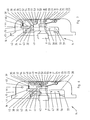
- the abutment section 49 is of stepped design and comprises three step surfaces 50, 51, 52, which are connected to each other by run-on slopes 53, 54, so that the abutment section 49 in its entirety extends obliquely to the abutment region 26 of the lock catch 9. Due to the oblique course of the contact section 49, the blocking section 48 has a smaller width on its side facing the free space 55 than on its side facing away from the free space 55. While the two step surfaces 50, 51 run parallel to the contact region 26 of the latch 9, the step surface 52 is formed to extend obliquely thereto, but with a smaller pitch than the run-on slopes 53, 54.
- the free space 55 in the extension direction has a reduced inside width, as in FIG Fig. 5 is shown. Since the blocking portion 48 at the lower end due to the oblique course of the abutment portion 49 has a reduced width, despite the reduced clearance of the free space 55, a partial penetration of the blocking portion 48 in the free space 55 is possible. According to Fig. 5 For example, the blocking portion 48 can penetrate into the free space 55 until the rear upper edge of the latch 9 forming the upper end of the abutment region 26 comes into contact with the run-on slope 52.
- the actuator 29 is moved further in the direction of the arrow 47. Since a further displacement of the blocking element 35 is not possible, the latching lug 42 of the spring element 38 is pushed back by the obliquely extending latching edge 43 against the spring bias, so that the actuator 29 moves relative to the blocking element 35 in the direction of the arrow 47 until it the in Fig. 6 achieved shown position corresponding to the locked position of the lock 14. Since in this position, the locking edge 43 is no longer engaged behind by the locking lug 42, the actuator 29 and the blocking element 35 are in a partially coupled position.
- the actuator 29 is moved further in the direction of arrow 56 until it is in Fig. 2 reached shown position.
- the locking lug 42 of the spring element 38 engages behind the latching edge 43 of the actuator 29 automatically again, so that after the complete unlocking of the lock 14 again in Fig. 2 shown initial state is reached and the actuator 29 and the blocking element 35 are again in their fully coupled position.
Priority Applications (1)
| Application Number | Priority Date | Filing Date | Title |
|---|---|---|---|
| PL08019545T PL2085543T3 (pl) | 2008-01-17 | 2008-11-07 | Zamek do drzwi |
Applications Claiming Priority (1)
| Application Number | Priority Date | Filing Date | Title |
|---|---|---|---|
| DE202008000676U DE202008000676U1 (de) | 2008-01-17 | 2008-01-17 | Schloss |
Publications (3)
| Publication Number | Publication Date |
|---|---|
| EP2085543A2 true EP2085543A2 (fr) | 2009-08-05 |
| EP2085543A3 EP2085543A3 (fr) | 2013-05-01 |
| EP2085543B1 EP2085543B1 (fr) | 2015-01-07 |
Family
ID=40691077
Family Applications (1)
| Application Number | Title | Priority Date | Filing Date |
|---|---|---|---|
| EP08019545.6A Active EP2085543B1 (fr) | 2008-01-17 | 2008-11-07 | Serrure |
Country Status (3)
| Country | Link |
|---|---|
| EP (1) | EP2085543B1 (fr) |
| DE (1) | DE202008000676U1 (fr) |
| PL (1) | PL2085543T3 (fr) |
Families Citing this family (1)
| Publication number | Priority date | Publication date | Assignee | Title |
|---|---|---|---|---|
| DE102010012736A1 (de) * | 2010-03-05 | 2011-09-08 | Assa Abloy Sicherheitstechnik Gmbh | Verriegelungseinrichtung für eine Tür und/oder Fenster mit zentraler Betätigungseinrichtung der Türöffner |
Citations (10)
| Publication number | Priority date | Publication date | Assignee | Title |
|---|---|---|---|---|
| DE209718C (fr) * | ||||
| US1842079A (en) * | 1928-02-24 | 1932-01-19 | Sargent & Co | Lock |
| AU556131B2 (en) * | 1982-03-17 | 1986-10-23 | Lane Hardware Pty. Ltd. | Lock |
| US4691543A (en) * | 1985-03-18 | 1987-09-08 | Watts John R | Deadlock with key operated locking cylinder |
| US4754624A (en) * | 1987-01-23 | 1988-07-05 | W&F Manufacturing | Lock assembly for sliding doors |
| EP0466677A2 (fr) * | 1990-06-27 | 1992-01-15 | Roto Frank Eisenwarenfabrik Aktiengesellschaft | Fermeture à plusieurs verrous |
| WO1998032940A1 (fr) * | 1997-01-22 | 1998-07-30 | Ferco International Ferrures Et Serrures De Batiment | Serrure a pene demi-tour pour porte ou fenetre |
| EP1020597A1 (fr) * | 1999-01-14 | 2000-07-19 | Karl Fliether GmbH & Co. | Serrure à crémone avec une serrure principal et une serrure complémentaire |
| EP1020594A2 (fr) * | 1999-01-18 | 2000-07-19 | Karl Fliether GmbH & Co. | Crémone |
| JP2005120703A (ja) * | 2003-10-16 | 2005-05-12 | Hinaka Seisakusho:Kk | ドアのラッチ装置 |
Family Cites Families (5)
| Publication number | Priority date | Publication date | Assignee | Title |
|---|---|---|---|---|
| AT366750B (de) * | 1980-11-13 | 1982-05-10 | Grundmann Rohrbacher Schlosser | Tuerverschluss |
| EP0653535B1 (fr) * | 1993-11-15 | 1997-03-26 | Schloss- und Beschlägefabrik AG | Serrure |
| DE29605517U1 (de) * | 1996-03-26 | 1997-07-24 | Gretsch Unitas Gmbh | Verriegelungseinrichtung |
| DE29916887U1 (de) * | 1999-09-25 | 2001-02-08 | Fliether Karl Gmbh & Co | Schloß |
| DE10341440A1 (de) * | 2003-09-09 | 2005-03-31 | Aug. Winkhaus Gmbh & Co. Kg | Treibstangenschloss |
-
2008
- 2008-01-17 DE DE202008000676U patent/DE202008000676U1/de not_active Expired - Lifetime
- 2008-11-07 EP EP08019545.6A patent/EP2085543B1/fr active Active
- 2008-11-07 PL PL08019545T patent/PL2085543T3/pl unknown
Patent Citations (10)
| Publication number | Priority date | Publication date | Assignee | Title |
|---|---|---|---|---|
| DE209718C (fr) * | ||||
| US1842079A (en) * | 1928-02-24 | 1932-01-19 | Sargent & Co | Lock |
| AU556131B2 (en) * | 1982-03-17 | 1986-10-23 | Lane Hardware Pty. Ltd. | Lock |
| US4691543A (en) * | 1985-03-18 | 1987-09-08 | Watts John R | Deadlock with key operated locking cylinder |
| US4754624A (en) * | 1987-01-23 | 1988-07-05 | W&F Manufacturing | Lock assembly for sliding doors |
| EP0466677A2 (fr) * | 1990-06-27 | 1992-01-15 | Roto Frank Eisenwarenfabrik Aktiengesellschaft | Fermeture à plusieurs verrous |
| WO1998032940A1 (fr) * | 1997-01-22 | 1998-07-30 | Ferco International Ferrures Et Serrures De Batiment | Serrure a pene demi-tour pour porte ou fenetre |
| EP1020597A1 (fr) * | 1999-01-14 | 2000-07-19 | Karl Fliether GmbH & Co. | Serrure à crémone avec une serrure principal et une serrure complémentaire |
| EP1020594A2 (fr) * | 1999-01-18 | 2000-07-19 | Karl Fliether GmbH & Co. | Crémone |
| JP2005120703A (ja) * | 2003-10-16 | 2005-05-12 | Hinaka Seisakusho:Kk | ドアのラッチ装置 |
Also Published As
| Publication number | Publication date |
|---|---|
| EP2085543A3 (fr) | 2013-05-01 |
| DE202008000676U1 (de) | 2009-05-28 |
| EP2085543B1 (fr) | 2015-01-07 |
| PL2085543T3 (pl) | 2015-06-30 |
Similar Documents
| Publication | Publication Date | Title |
|---|---|---|
| EP2860332B1 (fr) | Serrure à verrouillage automatique actionée par une poignée | |
| EP3372757A1 (fr) | Unité de verrouillage pour une installation de verrouillage d'une porte | |
| DE202008004173U1 (de) | Verriegelungsvorrichtung | |
| EP1739257B1 (fr) | Serrure | |
| DE102004013646A1 (de) | Panikschloss | |
| WO2012049127A1 (fr) | Serrure | |
| EP2085543B1 (fr) | Serrure | |
| DE102015000606A1 (de) | Verriegelungsvorrichtung für einen schwenkbar gelagerten Flügel | |
| EP3628801B1 (fr) | Dispositif de fermeture pour une porte et procédé pour ouvrir une porte | |
| EP2808468B1 (fr) | Dispositif de verrouillage pour un système de fermeture | |
| EP3112564A1 (fr) | Serrure à loquet à verrouillage automatique | |
| AT390989B (de) | Tuerschloss mit verschiebbarem riegel und falle | |
| EP2317047A2 (fr) | Agencement de ferrure | |
| EP3243981B1 (fr) | Serrure | |
| EP2746506B1 (fr) | Serrure de déclenchement | |
| EP2719850B1 (fr) | Serrure à mortaiser | |
| DE102017000346B4 (de) | Schloss mit Fallensperre | |
| DE202012012085U1 (de) | Schaltschloss | |
| WO1993004253A1 (fr) | Porte de securite et dispositif de securite pour le montage dans une porte | |
| DE102008016317B4 (de) | Schloss mit einer Anordnung zur Fallendrehung | |
| EP1790805A2 (fr) | Mécanisme d'actionnement à levier pour une crémone | |
| EP2865831B1 (fr) | Serrure | |
| EP1340873B1 (fr) | Dispositif de verrouillage | |
| EP2072726B1 (fr) | Serrure | |
| EP3907356A1 (fr) | Serrure à verrouillage automatique |
Legal Events
| Date | Code | Title | Description |
|---|---|---|---|
| PUAI | Public reference made under article 153(3) epc to a published international application that has entered the european phase |
Free format text: ORIGINAL CODE: 0009012 |
|
| AK | Designated contracting states |
Kind code of ref document: A2 Designated state(s): AT BE BG CH CY CZ DE DK EE ES FI FR GB GR HR HU IE IS IT LI LT LU LV MC MT NL NO PL PT RO SE SI SK TR |
|
| AX | Request for extension of the european patent |
Extension state: AL BA MK RS |
|
| RAP1 | Party data changed (applicant data changed or rights of an application transferred) |
Owner name: MACO VERMOEGENSVERWALTUNG GMBH |
|
| RAP1 | Party data changed (applicant data changed or rights of an application transferred) |
Owner name: MACO TECHNOLOGIE GMBH |
|
| PUAL | Search report despatched |
Free format text: ORIGINAL CODE: 0009013 |
|
| AK | Designated contracting states |
Kind code of ref document: A3 Designated state(s): AT BE BG CH CY CZ DE DK EE ES FI FR GB GR HR HU IE IS IT LI LT LU LV MC MT NL NO PL PT RO SE SI SK TR |
|
| AX | Request for extension of the european patent |
Extension state: AL BA MK RS |
|
| RIC1 | Information provided on ipc code assigned before grant |
Ipc: E05B 17/20 20060101ALI20130327BHEP Ipc: E05B 17/00 20060101ALI20130327BHEP Ipc: E05C 9/18 20060101ALI20130327BHEP Ipc: E05B 55/00 20060101AFI20130327BHEP |
|
| 17P | Request for examination filed |
Effective date: 20131002 |
|
| RBV | Designated contracting states (corrected) |
Designated state(s): AT BE BG CH CY CZ DE DK EE ES FI FR GB GR HR HU IE IS IT LI LT LU LV MC MT NL NO PL PT RO SE SI SK TR |
|
| AKX | Designation fees paid |
Designated state(s): AT DE FR IT PL SK |
|
| GRAP | Despatch of communication of intention to grant a patent |
Free format text: ORIGINAL CODE: EPIDOSNIGR1 |
|
| INTG | Intention to grant announced |
Effective date: 20140620 |
|
| GRAS | Grant fee paid |
Free format text: ORIGINAL CODE: EPIDOSNIGR3 |
|
| GRAP | Despatch of communication of intention to grant a patent |
Free format text: ORIGINAL CODE: EPIDOSNIGR1 |
|
| INTG | Intention to grant announced |
Effective date: 20140930 |
|
| GRAA | (expected) grant |
Free format text: ORIGINAL CODE: 0009210 |
|
| AK | Designated contracting states |
Kind code of ref document: B1 Designated state(s): AT DE FR IT PL SK |
|
| REG | Reference to a national code |
Ref country code: AT Ref legal event code: REF Ref document number: 705868 Country of ref document: AT Kind code of ref document: T Effective date: 20150215 |
|
| REG | Reference to a national code |
Ref country code: DE Ref legal event code: R096 Ref document number: 502008012582 Country of ref document: DE Effective date: 20150226 |
|
| REG | Reference to a national code |
Ref country code: PL Ref legal event code: T3 |
|
| REG | Reference to a national code |
Ref country code: SK Ref legal event code: T3 Ref document number: E 18451 Country of ref document: SK |
|
| REG | Reference to a national code |
Ref country code: DE Ref legal event code: R097 Ref document number: 502008012582 Country of ref document: DE |
|
| PLBE | No opposition filed within time limit |
Free format text: ORIGINAL CODE: 0009261 |
|
| STAA | Information on the status of an ep patent application or granted ep patent |
Free format text: STATUS: NO OPPOSITION FILED WITHIN TIME LIMIT |
|
| REG | Reference to a national code |
Ref country code: FR Ref legal event code: PLFP Year of fee payment: 8 |
|
| 26N | No opposition filed |
Effective date: 20151008 |
|
| REG | Reference to a national code |
Ref country code: FR Ref legal event code: PLFP Year of fee payment: 9 |
|
| REG | Reference to a national code |
Ref country code: FR Ref legal event code: PLFP Year of fee payment: 10 |
|
| PGFP | Annual fee paid to national office [announced via postgrant information from national office to epo] |
Ref country code: SK Payment date: 20171228 Year of fee payment: 10 |
|
| PGFP | Annual fee paid to national office [announced via postgrant information from national office to epo] |
Ref country code: AT Payment date: 20171221 Year of fee payment: 10 |
|
| REG | Reference to a national code |
Ref country code: AT Ref legal event code: MM01 Ref document number: 705868 Country of ref document: AT Kind code of ref document: T Effective date: 20181107 |
|
| REG | Reference to a national code |
Ref country code: SK Ref legal event code: MM4A Ref document number: E 18451 Country of ref document: SK Effective date: 20181107 |
|
| PG25 | Lapsed in a contracting state [announced via postgrant information from national office to epo] |
Ref country code: SK Free format text: LAPSE BECAUSE OF NON-PAYMENT OF DUE FEES Effective date: 20181107 |
|
| PG25 | Lapsed in a contracting state [announced via postgrant information from national office to epo] |
Ref country code: AT Free format text: LAPSE BECAUSE OF NON-PAYMENT OF DUE FEES Effective date: 20181107 |
|
| PGFP | Annual fee paid to national office [announced via postgrant information from national office to epo] |
Ref country code: IT Payment date: 20231124 Year of fee payment: 16 Ref country code: FR Payment date: 20231120 Year of fee payment: 16 Ref country code: DE Payment date: 20231121 Year of fee payment: 16 |
|
| PGFP | Annual fee paid to national office [announced via postgrant information from national office to epo] |
Ref country code: PL Payment date: 20231026 Year of fee payment: 16 |