EP2085155A1 - Verfahren und Vorrichtung zur Überprüfung der Unversehrtheit von Rohrleitungswänden - Google Patents
Verfahren und Vorrichtung zur Überprüfung der Unversehrtheit von Rohrleitungswänden Download PDFInfo
- Publication number
- EP2085155A1 EP2085155A1 EP08001849A EP08001849A EP2085155A1 EP 2085155 A1 EP2085155 A1 EP 2085155A1 EP 08001849 A EP08001849 A EP 08001849A EP 08001849 A EP08001849 A EP 08001849A EP 2085155 A1 EP2085155 A1 EP 2085155A1
- Authority
- EP
- European Patent Office
- Prior art keywords
- pipeline
- inspection tool
- wall
- brake wheel
- brake
- Prior art date
- Legal status (The legal status is an assumption and is not a legal conclusion. Google has not performed a legal analysis and makes no representation as to the accuracy of the status listed.)
- Withdrawn
Links
Images


Classifications
-
- G—PHYSICS
- G01—MEASURING; TESTING
- G01N—INVESTIGATING OR ANALYSING MATERIALS BY DETERMINING THEIR CHEMICAL OR PHYSICAL PROPERTIES
- G01N29/00—Investigating or analysing materials by the use of ultrasonic, sonic or infrasonic waves; Visualisation of the interior of objects by transmitting ultrasonic or sonic waves through the object
- G01N29/22—Details, e.g. general constructional or apparatus details
- G01N29/26—Arrangements for orientation or scanning by relative movement of the head and the sensor
- G01N29/265—Arrangements for orientation or scanning by relative movement of the head and the sensor by moving the sensor relative to a stationary material
-
- F—MECHANICAL ENGINEERING; LIGHTING; HEATING; WEAPONS; BLASTING
- F16—ENGINEERING ELEMENTS AND UNITS; GENERAL MEASURES FOR PRODUCING AND MAINTAINING EFFECTIVE FUNCTIONING OF MACHINES OR INSTALLATIONS; THERMAL INSULATION IN GENERAL
- F16L—PIPES; JOINTS OR FITTINGS FOR PIPES; SUPPORTS FOR PIPES, CABLES OR PROTECTIVE TUBING; MEANS FOR THERMAL INSULATION IN GENERAL
- F16L55/00—Devices or appurtenances for use in, or in connection with, pipes or pipe systems
- F16L55/26—Pigs or moles, i.e. devices movable in a pipe or conduit with or without self-contained propulsion means
- F16L55/28—Constructional aspects
- F16L55/30—Constructional aspects of the propulsion means, e.g. towed by cables
- F16L55/38—Constructional aspects of the propulsion means, e.g. towed by cables driven by fluid pressure
-
- G—PHYSICS
- G01—MEASURING; TESTING
- G01N—INVESTIGATING OR ANALYSING MATERIALS BY DETERMINING THEIR CHEMICAL OR PHYSICAL PROPERTIES
- G01N29/00—Investigating or analysing materials by the use of ultrasonic, sonic or infrasonic waves; Visualisation of the interior of objects by transmitting ultrasonic or sonic waves through the object
- G01N29/22—Details, e.g. general constructional or apparatus details
- G01N29/225—Supports, positioning or alignment in moving situation
-
- G—PHYSICS
- G01—MEASURING; TESTING
- G01N—INVESTIGATING OR ANALYSING MATERIALS BY DETERMINING THEIR CHEMICAL OR PHYSICAL PROPERTIES
- G01N29/00—Investigating or analysing materials by the use of ultrasonic, sonic or infrasonic waves; Visualisation of the interior of objects by transmitting ultrasonic or sonic waves through the object
- G01N29/22—Details, e.g. general constructional or apparatus details
- G01N29/24—Probes
- G01N29/2412—Probes using the magnetostrictive properties of the material to be examined, e.g. electromagnetic acoustic transducers [EMAT]
-
- F—MECHANICAL ENGINEERING; LIGHTING; HEATING; WEAPONS; BLASTING
- F16—ENGINEERING ELEMENTS AND UNITS; GENERAL MEASURES FOR PRODUCING AND MAINTAINING EFFECTIVE FUNCTIONING OF MACHINES OR INSTALLATIONS; THERMAL INSULATION IN GENERAL
- F16L—PIPES; JOINTS OR FITTINGS FOR PIPES; SUPPORTS FOR PIPES, CABLES OR PROTECTIVE TUBING; MEANS FOR THERMAL INSULATION IN GENERAL
- F16L2101/00—Uses or applications of pigs or moles
- F16L2101/30—Inspecting, measuring or testing
-
- G—PHYSICS
- G01—MEASURING; TESTING
- G01N—INVESTIGATING OR ANALYSING MATERIALS BY DETERMINING THEIR CHEMICAL OR PHYSICAL PROPERTIES
- G01N2291/00—Indexing codes associated with group G01N29/00
- G01N2291/26—Scanned objects
- G01N2291/263—Surfaces
- G01N2291/2636—Surfaces cylindrical from inside
Definitions
- the present invention relates to a method and an apparatus for inspecting the integrity of the wall of a pipeline, in particular a gas pipeline.
- Pipelines are used all around the world for transporting different kinds of media like natural gas, crude oil and refined products. From time to time the integrity of the pipeline wall has to be inspected. This includes geometric inspections like gauging the internal bore and the wall thickness and is in particular directed to detecting any cracks in the wall or other signs of wall fatigue.
- Known devices for such testings include a variety of techniques known as magnetic flux leakage (MFL), axial flow detection (AFD), electro-magnetic acoustic transducers (EMAT) and ultrasonic testing. While traveling along the pipeline, inspection data are collected. At the end of the journey, the collected inspection data will be analysed.
- the inspection tool should move at a moderate constant speed between 0.5 and 5 m/s.
- MFL inspection tools the build up of magnetic field in the pipeline wall is directly dependent upon the travel speed of the MFL inspection tool.
- ultrasonic inspection tools the resolution of the scanning of the pipeline wall becomes unsatisfactory above a certain travel speed.
- the maximum allowable travel speed might be increased, but there will always be a certain upper limit.
- a problem with this kind of active speed control consists in the complex electronic control needed to open and close the bypass according to the travel speed and the fact that such system naturally suffers from a minimum reaction time. That is, sudden changes of travel speed can not always be appropriately handled. For instance, the change of travel speed does not only depend on the reduction of throughput at take offs or increase of throughput at a tie in. It may well be that the inspection tool slows down or even gets stuck in a pipeline section due to increased frictional resistance in the pipeline or that due to changes in the pipeline inclination the weight of the inspection tool accelerates or slows down the inspection tool, which changes can occur relatively sudden.
- the control of the travel speed of the inspection tool within a pipeline is a particular problem when gas pipelines are inspected, because the gas column behind the inspection tool is pushing the inspection tool through the pipeline with a fair amount of pressure and, due to the compressibility of gas, at the same time is acting like a gas spring. That is, sudden changes occurring due to the overcoming of sections of increased frictional resistance will cause enormous acceleration of the inspection tool followed by a deceleration, sometimes up to a complete halt again.
- the liquid batch in which the ultrasonic inspection tool is contained is usually a water batch with a length of sometimes more than 1000 meters.
- the water batch is sealed with front and rear shields against any leakage to the front and rear.
- the length of the water column transported with the liquid batch between the front and rear shield is needed in order to compensate the loss of liquid, such as at take offs and tie ins.
- the present invention envisages a hydromechanical solution. More specifically, a brake unit is moved along the pipeline section together with the inspection tool in order to control the travel speed of the inspection tool.
- the brake unit comprises at least one brake wheel and preferably a plurality of brake wheels distributed over the circumference of the brake unit so as to come into contact with the pipeline wall. More specifically, the brake wheel is urged against the pipeline wall so as to enable the brake wheel to roll on the wall.
- a fluid is pumped through a throttle.
- a fluid pressure builds up in front of the throttle. The pressure drop over the throttle has to be overcome by action of the brake wheel, this creating a counterforce on the brake wheel rotation.
- This counterforce is transferred onto the pipeline wall as a frictional force, provided that the force with which the brake wheel is urged against the pipeline wall is sufficiently high. If such urging force is not enough to transmit a frictional force on the pipeline wall that exceeds the counterforce acting on the brake wheel, then the brake wheel will partly slide along the pipeline wall.
- the counterforce created on the brake wheel by the pressure drop over the throttle is transformed into a corresponding frictional force acting on the pipeline wall, and said frictional force basically corresponds to the braking force with which the inspection tool resists the driving pressure resulting from the products, such as gas, transported through the pipeline.
- gravitational driving forces caused by the weight of the overall apparatus must be considered. The gravitational driving force depends on the pipeline inclination angle and must also be compensated by the brake unit.
- a method and apparatus as described before is both reliable and not very complex. Sensors to determine the actual travel speed and any electric control logic can be dispensed with (but are not excluded).
- the solution is mainly mechanical and, if a liquid such as oil is used as the fluid to be pumped through the throttle, is hydromechanical.
- the hydromechanical apparatus is most responsive on any travel speed changes since the liquid is substantially incompressible so that pressure changes are transmitted instantaneously.
- the brake unit is configured such that the fluid pressure building up in front of the throttle increases progressively, more preferably exponentially, with an increase of the rotational speed of the brake wheel.
- the total brake force which is a function of the travel speed, first builds up moderately and then more and more aggressively.
- the operating point of the travel speed can be appropriately chosen so that it can be reached by slowly increasing the travel speed of the inspection tool, whereas above the operating point further acceleration of the inspection tool will very soon result in extremely high brake forces.
- the force with which the brake wheel is urged against the pipeline wall is increased with an increase of the travel speed. This is achieved by generating at least a part of such force with the pressure building up in front of the throttle.
- the fluid pressure building up in front of the throttle is, directly or indirectly, transmitted onto a brake wheel fixture on which the brake wheel is rotatably mounted.
- a brake wheel fixture on which the brake wheel is rotatably mounted.
- the brake wheel fixture with the brake wheel can be urged radially outwardly against the pipeline wall.
- a movable piston may be arranged between the brake wheel fixture and a body centrally arranged in the brake unit, the piston being so arranged that it urges apart the brake wheel fixture and the centrally arranged body when the fluid pressure from in front of the throttle is transmitted onto the brake wheel fixture.
- one end of the movable piston is supported on the centrally arranged body and the other end is arranged in a fluid chamber which is integrally connected to the brake wheel fixture.
- the fluid pressure transmitted from the throttle to the brake wheel fixture is then transmitted to said fluid chamber of the brake wheel fixture.
- the brake unit does not create any brake force unless the brake wheel rotates. Therefore, when the apparatus starts travelling, there is a likelihood that the brake wheel will not start rotating due to a lack of friction between the brake wheel and the pipeline wall. It is therefore preferred to always apply on the brake wheel a predetermined minimum force urging the brake wheel against the pipeline wall. Most preferably, such predetermined minimum force is provided from a pressure reservoir, such as a pneumatic pressure reservoir.
- two or more of the brake wheels are spaced apart in an axial direction, i.e. in a direction of movement of the brake unit. More specifically, if the brake unit has e.g. 16 brake wheels, 8 brake wheels may be distributed uniformly over the circumference of the brake unit, with always two brake wheels aligned in an axial direction. This way, the brake unit is stably held in the pipeline relative to the direction of movement. Also, due to the distance between the axially spaced apart brake wheels, the brake unit can easily pass take offs and tie ins in the pipeline.
- the outer contour of the brake unit may be made concave in an area between the two axially spaced apart brake wheels so as to enable the brake unit to be moved through curved pipeline sections.
- the afore described movable piston is advantageous as it allows the brake unit to conform to pipeline diameter changes during the travel through curved pipeline sections.
- the movable piston makes it possible to use the brake unit in pipelines of different diameter. The movable piston will then simply spread apart the brake wheel fixture and the centrally arranged body when the brake unit is used in a pipeline with an increased diameter.
- the inspection tool equipped with the afore described brake unit for the purpose of non-destructive inspection of the pipeline's wall integrity can be of many different types, known as magnetic flux leakage (MFL), axial flow detection (AFD) or electro-magnetic acoustic transducer (EMAT). Inspection tools of these types do not need to be placed in a liquid batch, unlike the previously mentioned ultrasonic inspection tools which need a liquid, typically water, to guide the ultrasonic waves between the ultrasonic head and the pipeline wall.
- MFL magnetic flux leakage
- ALD axial flow detection
- EMAT electro-magnetic acoustic transducer
- a shield may be provided which completely seals against the pipeline wall so as to prevent any by-passing of fluid that is advanced through the pipeline. This ensures that the maximum driving force is available at all times which allows the inspection tool to overcome even sections of strong resistance and/or with an extreme positive inclination.
- the inspection tool is actively slowed down solely by the brake unit, which is fixedly connected to the inspection tool either directly or indirectly and which may be placed in front of the shield or behind the shield.
- a second shield is needed so as to completely seal the liquid batch at a front and rear end thereof, in order to prevent any leakage of liquid from the liquid batch.
- the liquid is thus contained between the front and rear shields and the surrounding pipeline wall.
- the length of the liquid batch is chosen such that any loss of liquid in a radial direction, such as at take offs and tie ins, may be compensated.
- the weight of the overall inspecting system including the inspection tool and the water batch is, thus, enormous. It is therefore preferred to move a messenger liquid batch through the pipeline section prior to moving the overall inspecting system through the pipeline.
- the messenger liquid batch comprises a sufficient amount of liquid which may leak radially from the messenger liquid batch into gaps in the wall of the pipeline section as the messenger liquid batch is moved along the pipeline. This way, tie ins and take offs can be filled in advance, at least partly. Accordingly, the length and the weight of the liquid batch actually containing the inspection tool can be substantially reduced. Accordingly, since by the action of the brake unit less weight will have to be slowed down, the brake unit will be more effective and can be reduced in size.
- Figure 1 schematically shows the typical arrangement of a water batch comprising an ultrasonic inspection tool in a gas pipeline with its effective forces.
- typical driving forces there are to be considered the driving force F D of the gas pressure and the driving force F G through gravitation.
- the frictional resistance F R is to be considered.
- FIG. 2 shows the water batch 1 with the ultrasonic inspection tool 10 and a brake unit 100 in somewhat more detail.
- the ultrasonic inspection tool 10 is contained in the water column 2 of the water batch 1 and travels along the pipeline section 20 together with the water batch 1 due to a gas pressure excepted on a rear shield 3a by gas 21 advancing through the pipeline 20.
- Brake unit 100 is fixedly connected to a front shield 2 so as to slow down the front shield 3b, thereby slowing down the entire water batch 1.
- the water batch 1 can have an enormous length of several hundred meters and, thus, can have an enormous weight.
- a plurality of brake units 100 can be provided, should need arise.
- brake unit in the embodiment shown in figure 2 is contained inside the water batch 1 and connected to the front shield 2, it may well be connected to the ultrasonic tool 10 or to the rear shield 3, and it may also be placed in front of or behind the front or rear shields 2, 3 outside the water batch 1.
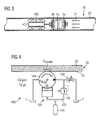
- Figure 3 shows a pipeline inspection apparatus comprising an MFL inspection tool rather than an ultrasonic tool. Accordingly, it is not necessary that the inspection tool 10 travels inside a water batch.
- the brake unit 100 is directly connected to the inspection tool 10 in front thereof (in the direction of travel through the gas pipeline), but could as well be placed behind the inspection tool 10.
- the inspection tool 10 comprises a front shield 2 and a rear shield 3 having the function of stabilizing the orientation of the inspection tool 10 inside the gas pipeline, with the rear shield 3 having the further function of sealing the gas pipeline's cross section so as to take up the complete pressure provided by the gas 21 which is advanced through the pipeline 20.
- MFL tools and other wall inspection tools can easily be equipped with a by-pass to maintain a high product flow rate in the pipeline.
- the brake wheel 101 of the brake unit 100 rolls over the inner surface 23 of the wall 22 of the pipeline section 20, it's rotational force is used to pump a fluid through a throttle 102.
- the throttle 102 is adjustable so as to accommodate for varying applications. It may be electronically adjustable, possibly by remote control.
- the brake wheel 101 constitutes a rotational pump, and there are many technical ways of transforming the rotational movement of the brake wheel 101 into pumping action. Due to the fluid pumped from a reservoir or tank T through the throttle 102 back into the reservoir T, pressure will build up in front of the throttle 102 and has to be overcome by the action of the brake wheel 101.
- the rotation of the brake wheel 101 is slowed down proportionally to the pressure building up in front of the throttle 102 and, furthermore, the higher the brake wheel rotation is, the higher is the pressure building up in front of the throttle 102 and, accordingly, the higher is the resulting force counteracting the brake wheel rotation.
- the brake wheel 101 actually rolls and does not slide over the inner surface 23 of the pipeline wall 22, such brake wheel rotation resistance force will be transferred onto the pipeline wall through frictional forces as a brake force F R, brake .
- the overall apparatus and, in particular, the brake unit 100 will have to be adjusted such that it travels with a predetermined speed under predetermined conditions (fluid pressure in the pipeline, inclination of the pipeline, etc.).
- the inspection apparatus only provides static frictions against the driving fluid pressure. Once the static frictions are overcome, the apparatus starts to move.
- the brake unit 100 builds up brake force which together with the dynamic friction of the apparatus provides the counterforce of the driving fluid pressure.
- the travel speed slowly increases until the driving force of the fluid pressure behind the apparatus equals the total forces provided by the brake unit and the dynamic friction of the entire unit.
- this equilibrium of forces should be obtained at the desired travel speed for the unit, e.g. 2 m/s. Accordingly, the throttle parameters have to be set appropriately to adjust this point of operation.
- the apparatus travels in a horizontal and friction wise undisturbed pipeline section. If the line remains horizontal and the frictional resistance of the apparatus does not change, the travel speed will not change either. In reality, however, both criteria do change and will disturb the equilibrium of forces. In the case of travel speed deceleration, the brake unit instantly reduces its brake force, as explained before. Ideally, the brake force decreases for exactly the same amount as the additional counterforce. This means that the original equilibrium of forces remains in place but the brake has changed its operating point, respectively the travel speed has lowered.
- the brake ceases to create brake forces at all and the driving fluid pressure entirely works only against the static frictional counterforce, so that the brake remains ineffective until the apparatus starts moving again. Then it controls the restart acceleration as described before.
- the brake unit increases its brake force immediately.
- the brake force decreases for exactly the same amount as the additional driving force. This means that the original equilibrium of forces remains in place but the brake has changed its operating point, respectively the travel speed has increased.
- a pressurized oil reservoir 105 is provided in the fluid line 103 behind a pressure relief valve 106.
- the pressure relief valve 106 is arranged in the fluid line 103 to ensure that the pressure in the fluid line 103 never decreases below the predetermined minimum pressure provided by the pressure reservoir 105. That is, when the brake wheel 101 does not rotate and, therefore, no pressure is built up before the throttle 102, the pressure relief valve ensures that the pressure of the pressure reservoir does not escape through the throttle 102.
- the tank T is itself pressurized and, thus, forms a pressure reservoir, then the specific pressurized oil reservoir 105 can be dispensed with.
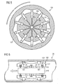
- the brake wheel 101 comprises a rotor 107 coming into contact with the inner surface 23 of the pipeline wall 22 and a stator 108 fixedly mounted on the brake unit 100.
- Hydraulic cylinders 109 are equally distributed over the circumference of the stator, in the present case ten hydraulic cylinders 109 are provided.
- One end of each hydraulic cylinder runs over a cam surface 110 of the rotor 107, whereas the respective other end of the hydraulic cylinder 109 defines an end wall 111 of a fluid chamber 112. Accordingly, the volume in the fluid chamber 112 changes depending upon the position of the hydraulic cylinder 109 relative to the cam surface 110 of the rotor 107.
- the fluid chamber 112 is connected to both a fluid line 113 of low pressure and a fluid line 114 of high pressure.
- the arrangement is such that by means of the hydraulic cylinders 109 the fluid, which is to be pumped through the throttle 102, is pumped from the low pressure line 113 into the high pressure line 114 leading to the throttle 102.
- Figure 6 shows the brake unit 100 of figures 2 and 3 in the pipeline section 20 in greater detail.
- at least four brake wheels 101 are symmetrically arranged with always two brake wheels 101 being aligned in the direction of travel.
- Figure 7 is a cross sectional view of pipeline 20 and brake unit 100 shown in figure 6 .
- 12 brake wheels 101 are distributed and equally spaced apart over the circumference of the pipeline wall 22.
- Each of the brake wheels 101 cooperates with a piston-cylinder-arrangement 104.
- the piston-cylinder-arrangement 104 comprises a movable piston 115, of which one end is supported on a centrally arranged, rod-like body 116 and the other end is arranged in a fluid chamber which is integrally connected to a fixture 117 housing the brake wheels 101.
- the fixture 117 and centrally arranged body 116 are displaceable relative to each other in a radial direction.
- the hydraulic cylinder 104 can force apart the brake wheel fixture 117 and the centrally arranged body 116, thereby allowing the brake unit to be used in pipelines with varying size or in differently sized pipelines.
- figure 8 shows the same brake unit 100 in a smaller sized pipeline 20 with a cross sectional diameter of 30 inch. Accordingly, the brake wheel fixture 117 and the centrally arranged body 116 are closer together as compared to figure 6 .
- the flexibility of the brake unit 100 to adapt to pipeline cross sections of different size is likewise advantageous to maintain proper contact with the pipeline wall when travelling through curved pipeline sections. This is shown in figures 9 and 10 for pipelines of smaller and larger diameter, respectively.
- the outer surface 118 of the brake unit is concave in the area between the axially spaced apart brake wheels 101.
Landscapes
- Physics & Mathematics (AREA)
- Chemical & Material Sciences (AREA)
- Engineering & Computer Science (AREA)
- General Health & Medical Sciences (AREA)
- General Physics & Mathematics (AREA)
- Pathology (AREA)
- Immunology (AREA)
- Biochemistry (AREA)
- Health & Medical Sciences (AREA)
- Life Sciences & Earth Sciences (AREA)
- Analytical Chemistry (AREA)
- Combustion & Propulsion (AREA)
- General Engineering & Computer Science (AREA)
- Electromagnetism (AREA)
- Fluid Mechanics (AREA)
- Mechanical Engineering (AREA)
- Investigating Or Analyzing Materials By The Use Of Ultrasonic Waves (AREA)
Priority Applications (1)
| Application Number | Priority Date | Filing Date | Title |
|---|---|---|---|
| EP08001849A EP2085155A1 (de) | 2008-01-31 | 2008-01-31 | Verfahren und Vorrichtung zur Überprüfung der Unversehrtheit von Rohrleitungswänden |
Applications Claiming Priority (1)
| Application Number | Priority Date | Filing Date | Title |
|---|---|---|---|
| EP08001849A EP2085155A1 (de) | 2008-01-31 | 2008-01-31 | Verfahren und Vorrichtung zur Überprüfung der Unversehrtheit von Rohrleitungswänden |
Publications (1)
| Publication Number | Publication Date |
|---|---|
| EP2085155A1 true EP2085155A1 (de) | 2009-08-05 |
Family
ID=39512562
Family Applications (1)
| Application Number | Title | Priority Date | Filing Date |
|---|---|---|---|
| EP08001849A Withdrawn EP2085155A1 (de) | 2008-01-31 | 2008-01-31 | Verfahren und Vorrichtung zur Überprüfung der Unversehrtheit von Rohrleitungswänden |
Country Status (1)
| Country | Link |
|---|---|
| EP (1) | EP2085155A1 (de) |
Cited By (14)
| Publication number | Priority date | Publication date | Assignee | Title |
|---|---|---|---|---|
| EP2315018A1 (de) * | 2009-10-20 | 2011-04-27 | Westinghouse Electric Company LLC | Wirbelstromprüfsonde |
| CN102809608A (zh) * | 2012-07-30 | 2012-12-05 | 燕山大学 | 内置机器人小车式大型筒节类件超声波自动探伤机 |
| CN103042017A (zh) * | 2011-10-17 | 2013-04-17 | 中国石油天然气集团公司 | 一种管道清管检测设备用速度控制系统执行机构 |
| CN103721986A (zh) * | 2014-01-02 | 2014-04-16 | 西南石油大学 | 一种带刹车片的清管器速度控制器 |
| NL2012839A (en) * | 2014-05-19 | 2014-06-26 | Röntgen Tech Dienst B V | Tool, method, and system for in-line inspection or treatment of a pipeline. |
| WO2014105438A1 (en) * | 2012-12-31 | 2014-07-03 | General Electric Company | Reference speed measurement for a non-destructive testing system |
| CN106870871A (zh) * | 2017-04-20 | 2017-06-20 | 温州市龙湾区市政工程公司 | 一种管道非开挖修复用爬行器 |
| CN106890748A (zh) * | 2017-04-19 | 2017-06-27 | 西南石油大学 | 一种带有紧急启动系统的涂膜清管器 |
| CN111530865A (zh) * | 2020-05-10 | 2020-08-14 | 贾小帅 | 一种基于反作用力原理的管道内壁用清洗装置 |
| JP2020148753A (ja) * | 2019-03-15 | 2020-09-17 | 株式会社デンロコーポレーション | 鋼管鉄塔部材内面の調査装置に用いられる保持治具 |
| CN112170395A (zh) * | 2020-09-26 | 2021-01-05 | 宜宾学院 | 一种清管器液控加速度控制器 |
| CN112338663A (zh) * | 2020-11-05 | 2021-02-09 | 张秀华 | 一种细长钢管内壁除锈装置 |
| CN112428037A (zh) * | 2020-11-05 | 2021-03-02 | 张秀华 | 一种钢管内壁清理装置 |
| CN114354740A (zh) * | 2022-03-09 | 2022-04-15 | 成都熊谷油气科技有限公司 | 一种管道检测系统 |
Citations (6)
| Publication number | Priority date | Publication date | Assignee | Title |
|---|---|---|---|---|
| US3058137A (en) * | 1960-01-13 | 1962-10-16 | Earl N Doyle | Pipe line treating apparatus |
| US4170902A (en) * | 1978-05-18 | 1979-10-16 | British Gas Corporation | Pipeline inspection vehicles |
| US4388871A (en) * | 1977-07-27 | 1983-06-21 | British Gas Corporation | Speed control system for a pipeline inspection vehicle |
| WO1986001751A1 (en) * | 1984-09-17 | 1986-03-27 | Per Storesund | Pipeline pig |
| US4769598A (en) * | 1985-03-27 | 1988-09-06 | Kopp Ag International Pipeline Services | Apparatus for electromagnetically testing the walls of pipelines |
| US5648613A (en) * | 1994-04-05 | 1997-07-15 | Gas Research Institute | Scan assembly and method for signal discrimination |
-
2008
- 2008-01-31 EP EP08001849A patent/EP2085155A1/de not_active Withdrawn
Patent Citations (6)
| Publication number | Priority date | Publication date | Assignee | Title |
|---|---|---|---|---|
| US3058137A (en) * | 1960-01-13 | 1962-10-16 | Earl N Doyle | Pipe line treating apparatus |
| US4388871A (en) * | 1977-07-27 | 1983-06-21 | British Gas Corporation | Speed control system for a pipeline inspection vehicle |
| US4170902A (en) * | 1978-05-18 | 1979-10-16 | British Gas Corporation | Pipeline inspection vehicles |
| WO1986001751A1 (en) * | 1984-09-17 | 1986-03-27 | Per Storesund | Pipeline pig |
| US4769598A (en) * | 1985-03-27 | 1988-09-06 | Kopp Ag International Pipeline Services | Apparatus for electromagnetically testing the walls of pipelines |
| US5648613A (en) * | 1994-04-05 | 1997-07-15 | Gas Research Institute | Scan assembly and method for signal discrimination |
Non-Patent Citations (1)
| Title |
|---|
| "The Australian Pipeliner", APIA COMPANY MEMBER NEWS, August 2003 (2003-08-01), pages 24 |
Cited By (23)
| Publication number | Priority date | Publication date | Assignee | Title |
|---|---|---|---|---|
| EP2315018A1 (de) * | 2009-10-20 | 2011-04-27 | Westinghouse Electric Company LLC | Wirbelstromprüfsonde |
| CN103042017A (zh) * | 2011-10-17 | 2013-04-17 | 中国石油天然气集团公司 | 一种管道清管检测设备用速度控制系统执行机构 |
| CN103042017B (zh) * | 2011-10-17 | 2015-06-10 | 中国石油天然气集团公司 | 一种管道清管检测设备用速度控制系统执行机构 |
| CN102809608B (zh) * | 2012-07-30 | 2014-11-12 | 燕山大学 | 内置机器人小车式大型筒节类件超声波自动探伤机 |
| CN102809608A (zh) * | 2012-07-30 | 2012-12-05 | 燕山大学 | 内置机器人小车式大型筒节类件超声波自动探伤机 |
| CN105074453A (zh) * | 2012-12-31 | 2015-11-18 | 通用电气公司 | 用于无损测试系统的参考速度测量 |
| WO2014105438A1 (en) * | 2012-12-31 | 2014-07-03 | General Electric Company | Reference speed measurement for a non-destructive testing system |
| US9003880B2 (en) | 2012-12-31 | 2015-04-14 | General Electric Company | Reference speed measurement for a non-destructive testing system |
| CN105074453B (zh) * | 2012-12-31 | 2018-12-14 | 通用电气公司 | 用于无损测试系统的参考速度测量 |
| CN103721986A (zh) * | 2014-01-02 | 2014-04-16 | 西南石油大学 | 一种带刹车片的清管器速度控制器 |
| NL2012839A (en) * | 2014-05-19 | 2014-06-26 | Röntgen Tech Dienst B V | Tool, method, and system for in-line inspection or treatment of a pipeline. |
| US10060567B2 (en) | 2014-05-19 | 2018-08-28 | Rontgen Technische Dienst B.V. | Tool, method, and system for in-line inspection or treatment of a pipeline |
| CN106890748B (zh) * | 2017-04-19 | 2023-03-31 | 西南石油大学 | 一种带有紧急启动系统的涂膜清管器及其使用方法 |
| CN106890748A (zh) * | 2017-04-19 | 2017-06-27 | 西南石油大学 | 一种带有紧急启动系统的涂膜清管器 |
| CN106870871A (zh) * | 2017-04-20 | 2017-06-20 | 温州市龙湾区市政工程公司 | 一种管道非开挖修复用爬行器 |
| JP2020148753A (ja) * | 2019-03-15 | 2020-09-17 | 株式会社デンロコーポレーション | 鋼管鉄塔部材内面の調査装置に用いられる保持治具 |
| JP7302138B2 (ja) | 2019-03-15 | 2023-07-04 | 株式会社デンロコーポレーション | 鋼管鉄塔部材内面の調査装置に用いられる保持治具 |
| CN111530865A (zh) * | 2020-05-10 | 2020-08-14 | 贾小帅 | 一种基于反作用力原理的管道内壁用清洗装置 |
| CN112170395A (zh) * | 2020-09-26 | 2021-01-05 | 宜宾学院 | 一种清管器液控加速度控制器 |
| CN112338663A (zh) * | 2020-11-05 | 2021-02-09 | 张秀华 | 一种细长钢管内壁除锈装置 |
| CN112428037A (zh) * | 2020-11-05 | 2021-03-02 | 张秀华 | 一种钢管内壁清理装置 |
| CN114354740A (zh) * | 2022-03-09 | 2022-04-15 | 成都熊谷油气科技有限公司 | 一种管道检测系统 |
| CN114354740B (zh) * | 2022-03-09 | 2022-05-31 | 成都熊谷油气科技有限公司 | 一种管道检测系统 |
Similar Documents
| Publication | Publication Date | Title |
|---|---|---|
| EP2085155A1 (de) | Verfahren und Vorrichtung zur Überprüfung der Unversehrtheit von Rohrleitungswänden | |
| CN100565169C (zh) | 检测海底直铺管道侧向稳定性的模拟方法及其模拟装置 | |
| CA2791775C (fr) | Procede et dispositif de detection de defaillance d'une servovalve | |
| EP0475923B1 (de) | Vorrichtung zur Kraftregulierung der Niederhalter einer Presse | |
| CN111512085B (zh) | 管道检查装置及其操作方法 | |
| US4170902A (en) | Pipeline inspection vehicles | |
| EP2423560A1 (de) | Rohrleitungsvorrichtung und Verfahren | |
| CN106442729A (zh) | 管外环焊缝扫查器 | |
| EP2841914B1 (de) | Testvorrichtung zur simulation von kraftfahrzeugzusammenstössen und verfahren zum betrieb einer testvorrichtung | |
| EP3682215B1 (de) | Geschwindigkeitsregelungsvorrichtung für ein intelligentes rohrleitungsinspektionsmessgerät | |
| JPS6145109A (ja) | 回転部材を孔内に取付ける装置 | |
| CA3037781C (fr) | Procede d'engagement de deux elements engrenage et dispositif d'entrainement mettant en oeuvre un tel procede | |
| EP3012614B1 (de) | Reibungsprüfer | |
| CN106092533B (zh) | 一种平衡式单金属密封试验装置 | |
| JPS62259784A (ja) | 掘削機の軸線方向ベアリングのための装置 | |
| CN106716092A (zh) | 液压扭矩计 | |
| EP3546792B1 (de) | Verfahren zum eingriff zweier zahnräder und antriebsvorrichtung zur durchführung eines derartigen verfahrens | |
| EP2985199A1 (de) | Bremssystem für ein fahrzeug | |
| US5477733A (en) | Projectile recovery device | |
| FR3107388B1 (fr) | Procédé et système d’aide à la navigation pour un aéronef par détection d’objets maritimes en vue d’un vol d’approche, d’une mise en vol stationnaire ou d’un atterrissage | |
| EP3620687A1 (de) | Verbindungsverfahren von zwei verzahnungselementen, und antriebsvorrichtung, bei der dieses verfahren angewandt wird | |
| CN116772035B (zh) | 可制动的控速管道内检测器载体 | |
| CA3022574A1 (en) | Method for testing operation of parking brake systems of machines | |
| RU2008103867A (ru) | Способ регулирования скорости и внутритрубный снаряд-дефектоскоп с регулируемой скоростью движения | |
| CN105492275A (zh) | 制动装置、制动方法及利用该装置或方法的车辆 |
Legal Events
| Date | Code | Title | Description |
|---|---|---|---|
| PUAI | Public reference made under article 153(3) epc to a published international application that has entered the european phase |
Free format text: ORIGINAL CODE: 0009012 |
|
| AK | Designated contracting states |
Kind code of ref document: A1 Designated state(s): AT BE BG CH CY CZ DE DK EE ES FI FR GB GR HR HU IE IS IT LI LT LU LV MC MT NL NO PL PT RO SE SI SK TR |
|
| AX | Request for extension of the european patent |
Extension state: AL BA MK RS |
|
| AKX | Designation fees paid | ||
| STAA | Information on the status of an ep patent application or granted ep patent |
Free format text: STATUS: THE APPLICATION IS DEEMED TO BE WITHDRAWN |
|
| 18D | Application deemed to be withdrawn |
Effective date: 20100206 |
|
| REG | Reference to a national code |
Ref country code: DE Ref legal event code: 8566 |