EP2084939B1 - Verfahren und einrichtung zum entfernen von beschichtungen auf einer metallstruktur - Google Patents
Verfahren und einrichtung zum entfernen von beschichtungen auf einer metallstruktur Download PDFInfo
- Publication number
- EP2084939B1 EP2084939B1 EP07834781A EP07834781A EP2084939B1 EP 2084939 B1 EP2084939 B1 EP 2084939B1 EP 07834781 A EP07834781 A EP 07834781A EP 07834781 A EP07834781 A EP 07834781A EP 2084939 B1 EP2084939 B1 EP 2084939B1
- Authority
- EP
- European Patent Office
- Prior art keywords
- temperature
- metal structure
- control unit
- oscillator
- coil
- Prior art date
- Legal status (The legal status is an assumption and is not a legal conclusion. Google has not performed a legal analysis and makes no representation as to the accuracy of the status listed.)
- Active
Links
Images

Classifications
-
- H—ELECTRICITY
- H05—ELECTRIC TECHNIQUES NOT OTHERWISE PROVIDED FOR
- H05B—ELECTRIC HEATING; ELECTRIC LIGHT SOURCES NOT OTHERWISE PROVIDED FOR; CIRCUIT ARRANGEMENTS FOR ELECTRIC LIGHT SOURCES, IN GENERAL
- H05B6/00—Heating by electric, magnetic or electromagnetic fields
- H05B6/02—Induction heating
- H05B6/10—Induction heating apparatus, other than furnaces, for specific applications
- H05B6/101—Induction heating apparatus, other than furnaces, for specific applications for local heating of metal pieces
-
- B—PERFORMING OPERATIONS; TRANSPORTING
- B08—CLEANING
- B08B—CLEANING IN GENERAL; PREVENTION OF FOULING IN GENERAL
- B08B7/00—Cleaning by methods not provided for in a single other subclass or a single group in this subclass
- B08B7/0064—Cleaning by methods not provided for in a single other subclass or a single group in this subclass by temperature changes
- B08B7/0071—Cleaning by methods not provided for in a single other subclass or a single group in this subclass by temperature changes by heating
-
- B—PERFORMING OPERATIONS; TRANSPORTING
- B44—DECORATIVE ARTS
- B44D—PAINTING OR ARTISTIC DRAWING, NOT OTHERWISE PROVIDED FOR; PRESERVING PAINTINGS; SURFACE TREATMENT TO OBTAIN SPECIAL ARTISTIC SURFACE EFFECTS OR FINISHES
- B44D3/00—Accessories or implements for use in connection with painting or artistic drawing, not otherwise provided for; Methods or devices for colour determination, selection, or synthesis, e.g. use of colour tables
- B44D3/16—Implements or apparatus for removing dry paint from surfaces, e.g. by scraping, by burning
- B44D3/166—Implements or apparatus for removing dry paint from surfaces, e.g. by scraping, by burning by heating, e.g. by burning
- B44D3/168—Implements or apparatus for removing dry paint from surfaces, e.g. by scraping, by burning by heating, e.g. by burning by electrically heating
-
- C—CHEMISTRY; METALLURGY
- C23—COATING METALLIC MATERIAL; COATING MATERIAL WITH METALLIC MATERIAL; CHEMICAL SURFACE TREATMENT; DIFFUSION TREATMENT OF METALLIC MATERIAL; COATING BY VACUUM EVAPORATION, BY SPUTTERING, BY ION IMPLANTATION OR BY CHEMICAL VAPOUR DEPOSITION, IN GENERAL; INHIBITING CORROSION OF METALLIC MATERIAL OR INCRUSTATION IN GENERAL
- C23G—CLEANING OR DE-GREASING OF METALLIC MATERIAL BY CHEMICAL METHODS OTHER THAN ELECTROLYSIS
- C23G5/00—Cleaning or de-greasing metallic material by other methods; Apparatus for cleaning or de-greasing metallic material with organic solvents
-
- H—ELECTRICITY
- H05—ELECTRIC TECHNIQUES NOT OTHERWISE PROVIDED FOR
- H05B—ELECTRIC HEATING; ELECTRIC LIGHT SOURCES NOT OTHERWISE PROVIDED FOR; CIRCUIT ARRANGEMENTS FOR ELECTRIC LIGHT SOURCES, IN GENERAL
- H05B6/00—Heating by electric, magnetic or electromagnetic fields
- H05B6/02—Induction heating
- H05B6/06—Control, e.g. of temperature, of power
-
- H—ELECTRICITY
- H05—ELECTRIC TECHNIQUES NOT OTHERWISE PROVIDED FOR
- H05B—ELECTRIC HEATING; ELECTRIC LIGHT SOURCES NOT OTHERWISE PROVIDED FOR; CIRCUIT ARRANGEMENTS FOR ELECTRIC LIGHT SOURCES, IN GENERAL
- H05B2213/00—Aspects relating both to resistive heating and to induction heating, covered by H05B3/00 and H05B6/00
- H05B2213/07—Heating plates with temperature control means
Definitions
- the present invention relates to a device and method for removing rust and coatings from the surface of metal structures.
- the invention may find applications in the oil and gas industry for the maintenance of pipelines, offshore oil platforms and chemical and petroleum tanks, in civil engineering for removing rust on bridges or other large metal structures, or in the maritime sector, e.g. on ships.
- a portable induction heater unit is placed on the hull plate.
- Said unit includes an induction coil driven by a powerful signal generator.
- the magnetic field from the induction coil will set up eddy currents in the steel plate, which will be transformed to heat by the ohmic losses in the steel.
- the heat will lift the paint layers and rust due both to the temperature and differences in expansion coefficients.
- the supplied heat should be sufficient to lift the paint.
- overheating must be avoided to prevent scorching of the paint and the emission of unpleasant and unhealthy gases.
- Overheating may also be harmful for objects on the inside of the plates, in particular if there are any inflammable gases present, and may even anneal the steel and change its properties in a undesirable way. Thus, it is very important to accurately control the supplied heat.
- the unit disclosed in NO 314296 is moved manually over the hull, and will naturally be moved with an uneven speed.
- a tachometer wheel is mounted on the unit. The wheel traces the movement and controls the induction field, i.e. the unit is adapted to supply a controlled amount of energy per area.
- the prior art system will control the supplied heat in a proper way under ideal conditions, it has a couple of shortcomings. Initially, the system must be manually set to the conditions prevailing on the ship in question, i.e. a mean value must be set that is adapted to the mean thickness of the paint layer. As the workers move to another part of the ship, these conditions may change due to changes in the thickness of the rust and paint, the thickness and the conductivity of the steel.
- the invention relates to a device for removing coatings from a metal structure, said device including a signal generator driving an induction coil that is adapted to be positioned on the structure and a control unit including a temperature sensor and which is adapted to control the power output of the signal generator in accordance with the sensed temperature.
- a control unit including a temperature sensor and which is adapted to control the power output of the signal generator in accordance with the sensed temperature.
- the temperature sensor is adapted to measure the temperature in the metal structure beneath layers of corrosion and the other coatings and the power output of the signal generator is a function of the temperature in the metal structure
- the invention relates to a method for removing coatings on a metal structure.
- Said method includes inducing alternating currents in the structure, determining a temperature and controlling the power of the induced current in accordance with said temperature. Further the method includes measuring the temperature in the metal structure beneath layers of corrosion and the other coatings, and controlling the power output of the signal generator (201) as a function of the temperature in the metal structure beneath the layers of corrosion and the other coatings.
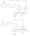
- Fig. 1 is a schematic block diagram showing the main components of a prior art device for removal of rust and coatings
- Fig. 2 is a schematic diagram over a corresponding device according to the present invention
- Fig. 3 is a diagram showing a temperature sensor for use in the device in Fig. 2 .
- Fig. 4 is an alternative embodiment of the temperature sensor in Fig. 3 .
- Fig. 5 is an alternative temperature sensor for use in the device illustrated in Fig. 2 .
- a prior art device for removing rust and paint is shown in Fig. 1 .
- the device is positioned on a metal surface that is coated with a layer of paint and rust 107.
- This layer may of course include other coatings as well, such as epoxy coatings, rubber, fire-retardant and other various coatings for preventing fouling of ships hulls, etc.
- a power supply unit 101 drives a coil 102.
- the power supply unit 101 acts as a power signal generator delivering a strong AC signal.
- the coil 102 will set up an alternating magnetic field in the metal structure.
- the magnetic field will induce an eddy current in the metal sheet 106 which will heat the metal.
- To control the heat induced in the steel e.g.
- a tachometer 104 or other motion sensor measures the rate of displacement of the device.
- a logic unit 105 reads the output from the tachometer 104 and the power delivered from the power supply unit 101.
- a control signal is produced and sent to the power supply unit. 101.
- This prior art device is adapted to supply a constant amount of heat per area of the metal surface.
- Fig. 2 shows a corresponding device designed according to the present invention.
- the device includes a power supply unit 201 driving a coil 202, as in the prior art device.
- this device includes a temperature sensor 208 that senses the temperature in the metal sheet 206 beneath the device.
- a microcontroller 209 reads the output from the temperature sensor 208 and the power delivered from the power supply unit 201.
- An algorithm is used to find the appropriate power required, which is compared with the actual power output.
- a control signal is produced and sent to the power supply unit 201. Then the temperature in the plate always may be held within a window of acceptable values, irrespective of local variables such as the thickness of the plate or the presence of objects at the inside of the sheet.
- the temperature sensor 208 must be able to measure the temperature in the metal sheet 206 beneath the coating 207. This precludes the use of devices based on measuring temperatures on the surface, such as off the shelf infrared ray detectors. This requirement has dictated the development of temperature sensors suited for this application.
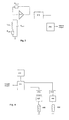
- Fig. 3 illustrates an inductive temperature sensor circuit.
- the sensor includes an oscillator circuit whose frequency is determined by a resonant circuit made of a coil L COIL and a parallel capacitance Cosc.
- the oscillator circuit is connected to the microcontroller 312.
- the coil L COIL is a conventional air-cored inductor, which when driven by a signal, couples electromagnetically to the sheet of metal. If the sensor is placed in close proximity of a steel structure, the oscillator coils will be affected by the steel corresponding to an iron core in a common resonator coil, increasing their inductivity.
- the invention is applicable for other metals as well provided they have magnetic properties.
- the oscillator circuit consists of the corresponding coil L COIL , connected via shielded cable to a parallel capacitance Cosc and a very high gain noninverting amplifier 310.
- the circuit oscillates at the natural resonant frequency of the LC combination, where the loop phase shift is zero and thus positive feedback occurs.
- the output of the oscillator is nominally a digital square wave with frequency:
- L COIL is the inductance of the coil
- R COIL is the loss in the circuit
- Cosc is the capacitance of the external capacitor. Cosc has of course also some internal losses, but they are generally negligible compared with the losses in the coil and is not included in the formula.
- L COIL is affected by the metal sheet, as is R COIL .
- the oscillator will induce a weak eddy current in the metal and the losses in this circuit are also included in R COIL .
- the losses in the metal sheet are dependent on temperature, and therefore the actual frequency of the oscillator will change in response to the temperature.
- the proximity of the metal sheet will also affect the inductance of the coil and thus the frequency of the oscillator, but the distance to the metal is here assumed to be constant, why this parameter may be ignored.
- inductance also is dependent on the proximity to the metal implies that this circuit may also be used to measure the distance to the metal sheet, provided that the temperature is held constant.
- C OSC should have a small temperature coefficient.
- the resistance R LOOP in the feedback loop is ideally set such that it is equal to the impedance of the LC tank at resonance, thus giving the largest possible signal at the amplifier input and thereby minimising the effect of noise.
- the microcontroller 312 observes the outputs from the PLL 313.
- the microcontroller is adapted to calculate the temperature of the metal from these data.
- the microcontroller may average several temperature readings.
- a reference oscillator may be incorporated in the circuit, as illustrated in Fig. 4 .
- This circuit includes a first oscillator 407 and a second oscillator 410 with resonance circuits 406 and 409, respectively.
- the oscillators are positioned on the metal; the first oscillator is placed in the hot zone beneath or near the induction heater, while the second oscillator is placed in the cold zone outside the area affected by the induction heater.
- the signal from each oscillator is sent to a microcontroller unit 412 that counts and compares the frequencies of the oscillators. For each signal it measures the time required for 200 oscillations to occur. The time is measured in processor clock cycles.
- the microcontroller 412 displays these data on a display device 414.
- the microcontroller is adapted to produce an output signal that is used to control the signal generator in the induction unit, as explained above.
- the circuit may include phase locked loops 413 a, b for removing jitter.
- FIG. 5 An alternative method for measuring the temperature in the metal is illustrated in Fig. 5 .
- the method is based on measuring the propagation speed of ultrasonic waves in the metal.
- the applied signal at the transducer A is creating an ultrasound wave travelling from A to the detector at point B.
- the applied signal could either be a single pulse or a signal with a frequency swept between the two frequencies fa 1 and fa 2 .
- This ultrasound wave is passing under the heating coil which is creating the temperature T.
- the detected signal at B is measured either in the time domain as a time delay from A to B or in the frequency domain.
- the delay or the measured frequency spectrum will be an unambiguous function of the average temperature T in the heated area under the coil.
- the methods used for determining the temperature in the metal sheet may find other applications than in devices for removing coating on metal.
Landscapes
- Chemical & Material Sciences (AREA)
- Engineering & Computer Science (AREA)
- Electromagnetism (AREA)
- Mechanical Engineering (AREA)
- Physics & Mathematics (AREA)
- Materials Engineering (AREA)
- General Chemical & Material Sciences (AREA)
- Chemical Kinetics & Catalysis (AREA)
- Metallurgy (AREA)
- Organic Chemistry (AREA)
- General Induction Heating (AREA)
- Application Of Or Painting With Fluid Materials (AREA)
- Manufacturing Of Printed Wiring (AREA)
Claims (11)
- Vorrichtung zur Entfernung von Beschichtungen (207) von einer Metallstruktur (206), welche Vorrichtung umfaßt: einen Signalgenerator (201), der eine Induktionsspule (202) treibt, welche dazu eingerichtet ist, an der Struktur (206) positioniert zu werden,
eine Steuereinheit (209, 312, 412) mit einem Temperaturfühler (208), dadurch gekennzeichnet, daß der Temperaturfühler einen Oszillator (307) mit einem Resonanzkreis (306) mit einer Spule und einem Kondensator umfaßt, wo der Resonanzkreis an einem geheizten Teil der Metallstruktur positioniert wird, wo die Steuereinheit (312) dazu eingerichtet ist, die Oszillationsfrequenz des Oszillators zu ermitteln und die Temperatur in der Metallstruktur unter Schichten von Korrosion und andreren Beschichtungen zu ermitteln, wo die Steuereinheit (209, 312, 412) ferner dazu eingerichtet ist, den Effektausgang des Signalgenerators (201) als Funktion der ermittelten Temperatur zu steuern. - Vorrichtung zur Entfernung von Beschichtungen (207) von einer Metallstruktur (206), welche Vorrichtung umfaßt: einen Signalgenerator (201), der eine Induktionsspule (202) treibt, welche dazu eingerichtet ist, an der Struktur (206) positioniert zu werden,
eine Steuereinheit (209, 312, 412) mit einem Temperaturfühler (208), dadurch gekennzeichnet, daß der Temperaturfühler umfaßt:einen ersten Oszillator (407) mit einem ersten Resonanzkreis (406) mit einer ersten Spule und einem ersten Kondensator, wo der erste Resonanzkreis an einem geheizten Teil der Metallstruktur positioniert wird,einen zweiten Oszillator (410) mit einem zweiten Resonanzkreis (409) mit einer zweiten Spule und einem zweiten Kondensator, wo der zweite Resonanzkreis an einem nicht geheizten Teil der Metallstruktur positioniert wird,wo die Steuereinheit (412) dazu eingerichtet ist, die Differenz der Frequenzen des ersten und des zweiten Oszillators zu ermitteln, um die Temperatur in der Metallstruktur unter Schichten von Korrosion und anderen Beschichtungen zu ermitteln, undwo die Steuereinheit (209, 312, 412) ferner dazu eingerichtet ist, den Effektausgang des Signalgenerators (201) als Funktion der ermittelten Temperatur zu steuern. - Vorrichtung gemäß Anspruch 2, in welcher die Steuereinheit (412) dazu eingerichtet ist, ein Steuersignal zu produzieren, das eine Funktion der Differenz zwischen den Frequenzwerten ist.
- Vorrichtung gemäß Anspruch 3, in welcher die Steuereinheit (412) eine Uhr umfaßt und dazu eingerichtet ist, die Frequenzen durch Zählen einer vordefinierten Anzahl von Oszillatorperioden in Taktzyklen zu ästimieren.
- Vorrichtung gemäß Anspruch 4, welche Vorrichtung erste und zweite phasengeschlossene Schleifen umfaßt, die dazu eingerichtet sind, ein Ausgangsignal aus dem ersten bzw. zweiten Oszillator zu empfangen und gesäuberte Versionen der Signale an die Steuereinheit zu liefern.
- Vorrichtung gemäß Anspruch 5, in welcher die Steuereinheit dazu eingerichtet ist, eine Anzahl von Ablesungen von Frequenzdifferenzen zu summieren und einen Mittelwert der Frequenzdifferenzen zu berechnen.
- Vorrichtung zur Entfernung von Beschichtungen (207) von einer Metallstruktur (206), welche Vorrichtung umfaßt:einen Signalgenerator (201), die eine Induktionsspule (202) treibt, die dazu eingerichtet ist, an der Struktur (206) positioniert zu werden,eine Steuereinheit (209, 312, 412) mit einem Temperaturfühler (208),dadurch gekennzeichnet, daß der Temperaturfühler umfaßt: einen ersten Wandler (A), der dazu eingerichtet ist, ein Ultraschallsignal in die Metallstruktur zu übertragen, einen zweiten Wandler (B), der dazu eingerichtet ist, das Ultraschallsignal zu empfangen, eine Prozessoreinheit, welche an den ersten und den zweiten Wandler verbunden ist und dazu eingerichtet ist, die Temperatur in der Metallstruktur unter Schichten von Korrosion und anderen Beschichtungen zu ermitteln, wo die Steuereinheit (209, 312, 412) ferner dazu eingerichtet ist, den Effektausgang des Signalgenerators (201) als Funktion der ermittelten Temperatur zu steuern.
- Verfahren zur Entfernung von Beschichtungen (207) von einer Metallstruktur (206), welches Verfahren umfaßt: Wechselstrom in der Struktur (206) zu induzieren und eine Temperatur zu ermitteln und den Effekt des induzierten Stromes nach der Temperatur zu steuern,
dadurch gekennzeichnet, daß die Temperatur ermittelt wird, indem eine erste Spule eines ersten Resonanzkreises an ein geheiztes Teil der Metallstruktur positioniert wird, wo der erste Resonanzkreis einen ersten Oszillator steuert, eine zweite Spule eines zweiten Resonanzkreises an ein nicht geheiztes Teil der Metallstruktur positioniert wird, wo der zweite Resonanzkreis einen zweiten Oszillator steuert,
die Differenz zwischen den Frequenzen des ersten und des zweiten Oszillators ermittelt wird, und die Temperatur in der Metallstruktur unter Schichten von Korrosion und anderen Beschichtungen als Funktion der Frequenzdifferenz ermittelt wird, und
der Effekt des induzierten Stromes als Funktion der Temperatur gesteuert wird. - Verfahren gemäß Anspruch 8, welches Verfahren die Säuberung von Signalen aus dem ersten bzw. zweiten Oszillator mit der ersten bzw. zweiten phasengeschlossenen Schleife umfaßt.
- Verfahren gemäß Anspruch 8, welches Verfahren umfaßt, eine Anzahl von Ablesungen von Frequenzdifferenzen zu summieren und einen Mittelwert der Frequenzdifferenzen zu berechnen.
- Verfahren zur Entfernung von Beschichtungen (207) von einer Metallstruktur (206), welches Verfahren umfaßt, Wechselstrom in der Struktur (206) zu induzieren und eine Temperatur zu ermitteln und den Effekt des induzierten Stromes nach dieser Temperatur zu steuern,
dadurch gekennzeichnet, daß die Temperatur bestimmt wird, indem ein erster Wandler an der Metallstruktur positioniert wird, ein zweiter Wandler an der Metallstruktur positioniert wird, ein Ultraschallsignal zwischen dem ersten und dem zweiten Wandler übertragen wird, die Temperatur in der Metallstruktur unter solchen Schichten als Funktion der Ausbreitungsgeschwindigkeit des Ultraschallsignals bestimmt wird, und der Effekt des induzierten Stromes als Funktion der Temperatur gesteuert wird.
Priority Applications (1)
| Application Number | Priority Date | Filing Date | Title |
|---|---|---|---|
| PL07834781T PL2084939T3 (pl) | 2006-10-19 | 2007-10-19 | Sposób i urządzenie do usuwania powłok z metalowej konstrukcji |
Applications Claiming Priority (2)
| Application Number | Priority Date | Filing Date | Title |
|---|---|---|---|
| NO20064745A NO333020B1 (no) | 2006-10-19 | 2006-10-19 | Innretning for a fjerne belegg pa en metallstruktur, samt en fremgangsmate for det samme. |
| PCT/NO2007/000372 WO2008048111A1 (en) | 2006-10-19 | 2007-10-19 | A method and device for removing coatings on a metal structure |
Publications (2)
| Publication Number | Publication Date |
|---|---|
| EP2084939A1 EP2084939A1 (de) | 2009-08-05 |
| EP2084939B1 true EP2084939B1 (de) | 2010-05-05 |
Family
ID=38983899
Family Applications (1)
| Application Number | Title | Priority Date | Filing Date |
|---|---|---|---|
| EP07834781A Active EP2084939B1 (de) | 2006-10-19 | 2007-10-19 | Verfahren und einrichtung zum entfernen von beschichtungen auf einer metallstruktur |
Country Status (13)
| Country | Link |
|---|---|
| US (1) | US7857914B2 (de) |
| EP (1) | EP2084939B1 (de) |
| CN (1) | CN101574015B (de) |
| AT (1) | ATE467330T1 (de) |
| CA (1) | CA2666812C (de) |
| DE (1) | DE602007006338D1 (de) |
| DK (1) | DK2084939T3 (de) |
| ES (1) | ES2345737T3 (de) |
| NO (1) | NO333020B1 (de) |
| PL (1) | PL2084939T3 (de) |
| PT (1) | PT2084939E (de) |
| WO (1) | WO2008048111A1 (de) |
| ZA (1) | ZA200903297B (de) |
Families Citing this family (9)
| Publication number | Priority date | Publication date | Assignee | Title |
|---|---|---|---|---|
| DE102008028272B4 (de) * | 2008-06-16 | 2016-07-28 | Trumpf Laser- Und Systemtechnik Gmbh | Verfahren und Vorrichtung zum induktiven Reinigen und Entschichten einer metallischen Werkstücksoberfläche |
| CN102573158B (zh) * | 2012-01-05 | 2014-04-09 | 江苏舾普泰克自动化科技有限公司 | 一种电磁感应式金属表面涂层去除方法及其设备 |
| NO338187B1 (no) * | 2014-09-19 | 2016-08-01 | Brynsloekken As | Antigroe ved hjelp av induksjon |
| CN105173033A (zh) * | 2015-09-30 | 2015-12-23 | 江苏天宝利自动化科技有限公司 | 一种对船舶除漆加热装置以及船舶除漆方法 |
| WO2018050550A1 (en) * | 2016-09-13 | 2018-03-22 | Ralph Meichtry | A method and device for removing dents |
| WO2018061091A1 (ja) * | 2016-09-27 | 2018-04-05 | 第一高周波工業株式会社 | 塗膜除去用加熱装置 |
| CN111669853A (zh) * | 2019-03-06 | 2020-09-15 | 南京航景信息科技有限公司 | 电磁感应式金属表面附着物去除设备的温度控制系统 |
| CN113514539B (zh) * | 2021-04-12 | 2024-09-17 | 爱德森(厦门)电子有限公司 | 一种金属表面覆层耐温与相对膨胀系数的检测方法和装置 |
| CN115254800B (zh) * | 2022-07-15 | 2023-06-13 | 业泓科技(成都)有限公司 | 探针清洁装置及探针清洁方法 |
Family Cites Families (13)
| Publication number | Priority date | Publication date | Assignee | Title |
|---|---|---|---|---|
| US3345874A (en) * | 1964-01-17 | 1967-10-10 | Tesla Np | Circuit arrangement for accurate measurement of temperatures or small temperature changes |
| US3743808A (en) | 1972-03-27 | 1973-07-03 | Growth International Inc | Method of controlling the induction heating of an elongated workpiece |
| CH637474A5 (fr) * | 1979-06-07 | 1983-07-29 | Bioself Int Inc | Thermometre electronique. |
| US4845332A (en) * | 1987-09-16 | 1989-07-04 | National Steel Corp. | Galvanneal induction furnace temperature control system |
| US5250776A (en) * | 1991-09-30 | 1993-10-05 | Tocco, Inc. | Apparatus and method of measuring temperature |
| BR9701473A (pt) | 1996-04-22 | 1998-09-08 | Illinois Tool Works | Sistema e método para o aquecimento indutivo de uma peça de trabalho e sistema para a aquecimento indutivo segmentado contínuo de uma peça de trabalho |
| GB9623139D0 (en) * | 1996-11-06 | 1997-01-08 | Euratom | A temperature sensor |
| CN1214534C (zh) * | 1997-04-07 | 2005-08-10 | 西门子公司 | 通过相关dds的数字afc调整电路 |
| US5938965A (en) | 1998-04-01 | 1999-08-17 | Tocco, Inc. | Inductor for removing paint from wire hooks |
| DE19940732B4 (de) | 1999-08-27 | 2009-07-09 | Starkstrom-Anlagen-Gesellschaft Mbh | Verfahren zum Entfernen von auf Stahlgittermasten von Hochspannungsfreileitungen befindlichen Farbbeschichtungen |
| NO314296B1 (no) * | 1999-11-02 | 2003-03-03 | Jak J Alveberg As | Fremgangsmåte og anordning ved fjerning av rust og maling fra en metallflate ved hjelp av induksjonsvarme |
| US6759910B2 (en) * | 2002-05-29 | 2004-07-06 | Xytrans, Inc. | Phase locked loop (PLL) frequency synthesizer and method |
| FR2843316B1 (fr) | 2002-08-12 | 2006-04-28 | Renault Sa | Procede de chauffage d'un produit de protection anticorrosion dispose sur un element de structure metallique ou electromagnetiquement susceptible et procede de protection associe |
-
2006
- 2006-10-19 NO NO20064745A patent/NO333020B1/no unknown
- 2006-12-14 US US11/639,501 patent/US7857914B2/en active Active
-
2007
- 2007-10-19 CA CA2666812A patent/CA2666812C/en active Active
- 2007-10-19 DE DE602007006338T patent/DE602007006338D1/de active Active
- 2007-10-19 WO PCT/NO2007/000372 patent/WO2008048111A1/en not_active Ceased
- 2007-10-19 EP EP07834781A patent/EP2084939B1/de active Active
- 2007-10-19 PT PT07834781T patent/PT2084939E/pt unknown
- 2007-10-19 AT AT07834781T patent/ATE467330T1/de active
- 2007-10-19 CN CN2007800472299A patent/CN101574015B/zh active Active
- 2007-10-19 DK DK07834781.2T patent/DK2084939T3/da active
- 2007-10-19 ES ES07834781T patent/ES2345737T3/es active Active
- 2007-10-19 PL PL07834781T patent/PL2084939T3/pl unknown
-
2009
- 2009-05-13 ZA ZA2009/03297A patent/ZA200903297B/en unknown
Also Published As
| Publication number | Publication date |
|---|---|
| DK2084939T3 (da) | 2010-08-30 |
| US20080092919A1 (en) | 2008-04-24 |
| ZA200903297B (en) | 2009-12-30 |
| WO2008048111A1 (en) | 2008-04-24 |
| CN101574015A (zh) | 2009-11-04 |
| ES2345737T3 (es) | 2010-09-30 |
| PL2084939T3 (pl) | 2010-12-31 |
| DE602007006338D1 (de) | 2010-06-17 |
| CA2666812A1 (en) | 2008-04-24 |
| ATE467330T1 (de) | 2010-05-15 |
| NO20064745L (no) | 2008-04-22 |
| US7857914B2 (en) | 2010-12-28 |
| CN101574015B (zh) | 2012-02-22 |
| PT2084939E (pt) | 2010-08-11 |
| NO333020B1 (no) | 2013-02-18 |
| CA2666812C (en) | 2013-11-19 |
| EP2084939A1 (de) | 2009-08-05 |
Similar Documents
| Publication | Publication Date | Title |
|---|---|---|
| EP2084939B1 (de) | Verfahren und einrichtung zum entfernen von beschichtungen auf einer metallstruktur | |
| US7673525B2 (en) | Sensor system for pipe and flow condition monitoring of a pipeline configured for flowing hydrocarbon mixtures | |
| MX2011007904A (es) | Metodo y dispositivo para medir el espesor de cualquier deposito de material en una pared interna de una estructura. | |
| US20080163692A1 (en) | System and method for using one or more thermal sensor probes for flow analysis, flow assurance and pipe condition monitoring of a pipeline for flowing hydrocarbons | |
| JP5866680B2 (ja) | 部分放電位置標定方法及び部分放電位置標定装置 | |
| US20040173021A1 (en) | Ultrasonic liquid level monitor | |
| CN104964659B (zh) | 耐高温型凝固坯壳厚度电磁超声扫频检测方法及装置 | |
| JP2024073506A (ja) | 冶金炉の耐火材料の厚さと摩耗状態との両方を推定するためのシステムおよび方法 | |
| US6363787B1 (en) | Apparatus and method for measuring the thickness of a coating | |
| CN108072868A (zh) | 一种基于fmcw雷达信号频率细化的高精度测距方法 | |
| CN103941261B (zh) | 相位敏感式定点测冰系统 | |
| JP2001281228A (ja) | 電磁超音波計測方法 | |
| JP2008070340A (ja) | 超音波を用いた温度測定方法 | |
| JP4411734B2 (ja) | 熱間超音波厚さ計及び厚さ計測方法 | |
| JP2772481B2 (ja) | 超音波測定方法及び超音波測定装置 | |
| JP2011232281A (ja) | 導電体の温度測定方法および温度測定装置 | |
| JP4674007B2 (ja) | 配管内の液位測定装置及び液位測定方法 | |
| Shi et al. | Non-contact and non-invasive water level measurement outside metal pipes with electromagnetic acoustic resonance | |
| JP7065304B2 (ja) | 水位検知装置および誘導加熱機器、ならびに、これらを備えた水位検知システム | |
| Wang et al. | A theoretical computation model of magnetostrictive guided waves NDT output signals in ferromagnetic cylinder | |
| RU2549614C1 (ru) | Способ возбуждения акустических колебаний в электропроводящих материалах | |
| Zhang et al. | A Novel Detection of Vessel Liquid Level Based on Echo Identification | |
| Sablik et al. | Evaluation of electromagnetic radiative noise magnetostrictively coupled to elastic vibrations in steel pipes | |
| CHO et al. | A STUDY OF GUIDED ULTRASONIC WAVE APPLICATION FOR HEAT EXCHANGER PERFORMANCE IMPROVEMENT | |
| JP2001153733A (ja) | 音響式温度測定装置及び方法 |
Legal Events
| Date | Code | Title | Description |
|---|---|---|---|
| PUAI | Public reference made under article 153(3) epc to a published international application that has entered the european phase |
Free format text: ORIGINAL CODE: 0009012 |
|
| 17P | Request for examination filed |
Effective date: 20090518 |
|
| AK | Designated contracting states |
Kind code of ref document: A1 Designated state(s): AT BE BG CH CY CZ DE DK EE ES FI FR GB GR HU IE IS IT LI LT LU LV MC MT NL PL PT RO SE SI SK TR |
|
| GRAP | Despatch of communication of intention to grant a patent |
Free format text: ORIGINAL CODE: EPIDOSNIGR1 |
|
| DAX | Request for extension of the european patent (deleted) | ||
| GRAS | Grant fee paid |
Free format text: ORIGINAL CODE: EPIDOSNIGR3 |
|
| GRAA | (expected) grant |
Free format text: ORIGINAL CODE: 0009210 |
|
| AK | Designated contracting states |
Kind code of ref document: B1 Designated state(s): AT BE BG CH CY CZ DE DK EE ES FI FR GB GR HU IE IS IT LI LT LU LV MC MT NL PL PT RO SE SI SK TR |
|
| REG | Reference to a national code |
Ref country code: GB Ref legal event code: FG4D |
|
| REG | Reference to a national code |
Ref country code: CH Ref legal event code: EP |
|
| REG | Reference to a national code |
Ref country code: IE Ref legal event code: FG4D |
|
| REF | Corresponds to: |
Ref document number: 602007006338 Country of ref document: DE Date of ref document: 20100617 Kind code of ref document: P |
|
| REG | Reference to a national code |
Ref country code: RO Ref legal event code: EPE |
|
| REG | Reference to a national code |
Ref country code: PT Ref legal event code: SC4A Free format text: AVAILABILITY OF NATIONAL TRANSLATION Effective date: 20100804 |
|
| REG | Reference to a national code |
Ref country code: NL Ref legal event code: T3 Ref country code: SE Ref legal event code: TRGR |
|
| REG | Reference to a national code |
Ref country code: DK Ref legal event code: T3 |
|
| REG | Reference to a national code |
Ref country code: CH Ref legal event code: NV Representative=s name: PATENTANWAELTE SCHAAD, BALASS, MENZL & PARTNER AG |
|
| REG | Reference to a national code |
Ref country code: ES Ref legal event code: FG2A Ref document number: 2345737 Country of ref document: ES Kind code of ref document: T3 |
|
| LTIE | Lt: invalidation of european patent or patent extension |
Effective date: 20100505 |
|
| PG25 | Lapsed in a contracting state [announced via postgrant information from national office to epo] |
Ref country code: LT Free format text: LAPSE BECAUSE OF FAILURE TO SUBMIT A TRANSLATION OF THE DESCRIPTION OR TO PAY THE FEE WITHIN THE PRESCRIBED TIME-LIMIT Effective date: 20100505 |
|
| PG25 | Lapsed in a contracting state [announced via postgrant information from national office to epo] |
Ref country code: LV Free format text: LAPSE BECAUSE OF FAILURE TO SUBMIT A TRANSLATION OF THE DESCRIPTION OR TO PAY THE FEE WITHIN THE PRESCRIBED TIME-LIMIT Effective date: 20100505 Ref country code: IS Free format text: LAPSE BECAUSE OF FAILURE TO SUBMIT A TRANSLATION OF THE DESCRIPTION OR TO PAY THE FEE WITHIN THE PRESCRIBED TIME-LIMIT Effective date: 20100905 Ref country code: SI Free format text: LAPSE BECAUSE OF FAILURE TO SUBMIT A TRANSLATION OF THE DESCRIPTION OR TO PAY THE FEE WITHIN THE PRESCRIBED TIME-LIMIT Effective date: 20100505 |
|
| PG25 | Lapsed in a contracting state [announced via postgrant information from national office to epo] |
Ref country code: CY Free format text: LAPSE BECAUSE OF FAILURE TO SUBMIT A TRANSLATION OF THE DESCRIPTION OR TO PAY THE FEE WITHIN THE PRESCRIBED TIME-LIMIT Effective date: 20100616 |
|
| REG | Reference to a national code |
Ref country code: PL Ref legal event code: T3 |
|
| PG25 | Lapsed in a contracting state [announced via postgrant information from national office to epo] |
Ref country code: EE Free format text: LAPSE BECAUSE OF FAILURE TO SUBMIT A TRANSLATION OF THE DESCRIPTION OR TO PAY THE FEE WITHIN THE PRESCRIBED TIME-LIMIT Effective date: 20100505 |
|
| PG25 | Lapsed in a contracting state [announced via postgrant information from national office to epo] |
Ref country code: SK Free format text: LAPSE BECAUSE OF FAILURE TO SUBMIT A TRANSLATION OF THE DESCRIPTION OR TO PAY THE FEE WITHIN THE PRESCRIBED TIME-LIMIT Effective date: 20100505 |
|
| PLBE | No opposition filed within time limit |
Free format text: ORIGINAL CODE: 0009261 |
|
| STAA | Information on the status of an ep patent application or granted ep patent |
Free format text: STATUS: NO OPPOSITION FILED WITHIN TIME LIMIT |
|
| 26N | No opposition filed |
Effective date: 20110208 |
|
| REG | Reference to a national code |
Ref country code: DE Ref legal event code: R097 Ref document number: 602007006338 Country of ref document: DE Effective date: 20110207 |
|
| PG25 | Lapsed in a contracting state [announced via postgrant information from national office to epo] |
Ref country code: MC Free format text: LAPSE BECAUSE OF NON-PAYMENT OF DUE FEES Effective date: 20101031 Ref country code: GR Free format text: LAPSE BECAUSE OF FAILURE TO SUBMIT A TRANSLATION OF THE DESCRIPTION OR TO PAY THE FEE WITHIN THE PRESCRIBED TIME-LIMIT Effective date: 20100806 |
|
| PG25 | Lapsed in a contracting state [announced via postgrant information from national office to epo] |
Ref country code: IE Free format text: LAPSE BECAUSE OF NON-PAYMENT OF DUE FEES Effective date: 20101019 |
|
| PG25 | Lapsed in a contracting state [announced via postgrant information from national office to epo] |
Ref country code: MT Free format text: LAPSE BECAUSE OF FAILURE TO SUBMIT A TRANSLATION OF THE DESCRIPTION OR TO PAY THE FEE WITHIN THE PRESCRIBED TIME-LIMIT Effective date: 20100505 Ref country code: IT Free format text: LAPSE BECAUSE OF NON-PAYMENT OF DUE FEES Effective date: 20101019 |
|
| PG25 | Lapsed in a contracting state [announced via postgrant information from national office to epo] |
Ref country code: HU Free format text: LAPSE BECAUSE OF FAILURE TO SUBMIT A TRANSLATION OF THE DESCRIPTION OR TO PAY THE FEE WITHIN THE PRESCRIBED TIME-LIMIT Effective date: 20101106 Ref country code: BG Free format text: LAPSE BECAUSE OF FAILURE TO SUBMIT A TRANSLATION OF THE DESCRIPTION OR TO PAY THE FEE WITHIN THE PRESCRIBED TIME-LIMIT Effective date: 20100505 Ref country code: LU Free format text: LAPSE BECAUSE OF NON-PAYMENT OF DUE FEES Effective date: 20101019 |
|
| PG25 | Lapsed in a contracting state [announced via postgrant information from national office to epo] |
Ref country code: BG Free format text: LAPSE BECAUSE OF FAILURE TO SUBMIT A TRANSLATION OF THE DESCRIPTION OR TO PAY THE FEE WITHIN THE PRESCRIBED TIME-LIMIT Effective date: 20100805 |
|
| REG | Reference to a national code |
Ref country code: FR Ref legal event code: PLFP Year of fee payment: 9 |
|
| REG | Reference to a national code |
Ref country code: FR Ref legal event code: PLFP Year of fee payment: 10 |
|
| REG | Reference to a national code |
Ref country code: FR Ref legal event code: PLFP Year of fee payment: 11 |
|
| REG | Reference to a national code |
Ref country code: FR Ref legal event code: PLFP Year of fee payment: 12 |
|
| PGFP | Annual fee paid to national office [announced via postgrant information from national office to epo] |
Ref country code: PT Payment date: 20250930 Year of fee payment: 19 |
|
| PGFP | Annual fee paid to national office [announced via postgrant information from national office to epo] |
Ref country code: TR Payment date: 20250930 Year of fee payment: 19 |
|
| REG | Reference to a national code |
Ref country code: CH Ref legal event code: U11 Free format text: ST27 STATUS EVENT CODE: U-0-0-U10-U11 (AS PROVIDED BY THE NATIONAL OFFICE) Effective date: 20251101 |
|
| PGFP | Annual fee paid to national office [announced via postgrant information from national office to epo] |
Ref country code: NL Payment date: 20251027 Year of fee payment: 19 |
|
| PGFP | Annual fee paid to national office [announced via postgrant information from national office to epo] |
Ref country code: DE Payment date: 20251028 Year of fee payment: 19 |
|
| PGFP | Annual fee paid to national office [announced via postgrant information from national office to epo] |
Ref country code: GB Payment date: 20251021 Year of fee payment: 19 |
|
| PGFP | Annual fee paid to national office [announced via postgrant information from national office to epo] |
Ref country code: AT Payment date: 20250917 Year of fee payment: 19 |
|
| PGFP | Annual fee paid to national office [announced via postgrant information from national office to epo] |
Ref country code: FI Payment date: 20251027 Year of fee payment: 19 Ref country code: DK Payment date: 20251024 Year of fee payment: 19 Ref country code: IT Payment date: 20251024 Year of fee payment: 19 |
|
| PGFP | Annual fee paid to national office [announced via postgrant information from national office to epo] |
Ref country code: FR Payment date: 20251027 Year of fee payment: 19 |
|
| PGFP | Annual fee paid to national office [announced via postgrant information from national office to epo] |
Ref country code: BE Payment date: 20251027 Year of fee payment: 19 |
|
| PGFP | Annual fee paid to national office [announced via postgrant information from national office to epo] |
Ref country code: SE Payment date: 20251024 Year of fee payment: 19 Ref country code: CH Payment date: 20251101 Year of fee payment: 19 |
|
| PGFP | Annual fee paid to national office [announced via postgrant information from national office to epo] |
Ref country code: CZ Payment date: 20251002 Year of fee payment: 19 |
|
| PGFP | Annual fee paid to national office [announced via postgrant information from national office to epo] |
Ref country code: PL Payment date: 20251006 Year of fee payment: 19 |
|
| PGFP | Annual fee paid to national office [announced via postgrant information from national office to epo] |
Ref country code: RO Payment date: 20251007 Year of fee payment: 19 |
|
| PGFP | Annual fee paid to national office [announced via postgrant information from national office to epo] |
Ref country code: ES Payment date: 20251118 Year of fee payment: 19 |