EP2083971B1 - Autonomer mobiler roboter, der hindernisse umgehen kann, und verfahren dafür - Google Patents
Autonomer mobiler roboter, der hindernisse umgehen kann, und verfahren dafür Download PDFInfo
- Publication number
- EP2083971B1 EP2083971B1 EP07708566A EP07708566A EP2083971B1 EP 2083971 B1 EP2083971 B1 EP 2083971B1 EP 07708566 A EP07708566 A EP 07708566A EP 07708566 A EP07708566 A EP 07708566A EP 2083971 B1 EP2083971 B1 EP 2083971B1
- Authority
- EP
- European Patent Office
- Prior art keywords
- mobile robot
- autonomous mobile
- unit
- moving object
- obstacle
- Prior art date
- Legal status (The legal status is an assumption and is not a legal conclusion. Google has not performed a legal analysis and makes no representation as to the accuracy of the status listed.)
- Not-in-force
Links
Images



Classifications
-
- G—PHYSICS
- G05—CONTROLLING; REGULATING
- G05D—SYSTEMS FOR CONTROLLING OR REGULATING NON-ELECTRIC VARIABLES
- G05D1/00—Control of position, course, altitude or attitude of land, water, air or space vehicles, e.g. using automatic pilots
- G05D1/02—Control of position or course in two dimensions
- G05D1/021—Control of position or course in two dimensions specially adapted to land vehicles
- G05D1/0227—Control of position or course in two dimensions specially adapted to land vehicles using mechanical sensing means, e.g. for sensing treated area
-
- B—PERFORMING OPERATIONS; TRANSPORTING
- B25—HAND TOOLS; PORTABLE POWER-DRIVEN TOOLS; MANIPULATORS
- B25J—MANIPULATORS; CHAMBERS PROVIDED WITH MANIPULATION DEVICES
- B25J9/00—Program-controlled manipulators
- B25J9/16—Program controls
- B25J9/1656—Program controls characterised by programming, planning systems for manipulators
- B25J9/1664—Program controls characterised by programming, planning systems for manipulators characterised by motion, path, trajectory planning
- B25J9/1666—Avoiding collision or forbidden zones
-
- B—PERFORMING OPERATIONS; TRANSPORTING
- B25—HAND TOOLS; PORTABLE POWER-DRIVEN TOOLS; MANIPULATORS
- B25J—MANIPULATORS; CHAMBERS PROVIDED WITH MANIPULATION DEVICES
- B25J19/00—Accessories fitted to manipulators, e.g. for monitoring, for viewing; Safety devices combined with or specially adapted for use in connection with manipulators
- B25J19/02—Sensing devices
-
- G—PHYSICS
- G05—CONTROLLING; REGULATING
- G05D—SYSTEMS FOR CONTROLLING OR REGULATING NON-ELECTRIC VARIABLES
- G05D1/00—Control of position, course, altitude or attitude of land, water, air or space vehicles, e.g. using automatic pilots
- G05D1/02—Control of position or course in two dimensions
- G05D1/021—Control of position or course in two dimensions specially adapted to land vehicles
- G05D1/0212—Control of position or course in two dimensions specially adapted to land vehicles with means for defining a desired trajectory
-
- G—PHYSICS
- G05—CONTROLLING; REGULATING
- G05D—SYSTEMS FOR CONTROLLING OR REGULATING NON-ELECTRIC VARIABLES
- G05D1/00—Control of position, course, altitude or attitude of land, water, air or space vehicles, e.g. using automatic pilots
- G05D1/02—Control of position or course in two dimensions
- G05D1/021—Control of position or course in two dimensions specially adapted to land vehicles
- G05D1/0231—Control of position or course in two dimensions specially adapted to land vehicles using optical position detecting means
- G05D1/0238—Control of position or course in two dimensions specially adapted to land vehicles using optical position detecting means using obstacle or wall sensors
-
- Y—GENERAL TAGGING OF NEW TECHNOLOGICAL DEVELOPMENTS; GENERAL TAGGING OF CROSS-SECTIONAL TECHNOLOGIES SPANNING OVER SEVERAL SECTIONS OF THE IPC; TECHNICAL SUBJECTS COVERED BY FORMER USPC CROSS-REFERENCE ART COLLECTIONS [XRACs] AND DIGESTS
- Y10—TECHNICAL SUBJECTS COVERED BY FORMER USPC
- Y10S—TECHNICAL SUBJECTS COVERED BY FORMER USPC CROSS-REFERENCE ART COLLECTIONS [XRACs] AND DIGESTS
- Y10S901/00—Robots
- Y10S901/01—Mobile robot
Definitions
- the present invention relates to a method of controlling a movement of an autonomous mobile robot, and more particularly to an autonomous mobile robot detouring an obstacle existing in a moving direction of the autonomous mobile robot when moving by being led by a moving object connected thereto, and a method of detouring an obstacle using the same.
- an autonomous mobile robot have been developed to be able to cope with an unknown environment without previous knowledge.
- This autonomous mobile robot is used in various fields.
- the autonomous mobile robot is used to help the handicapped, convey products in a factory, perform space exploration, substitute human labor in a dangerous environment such as a nuclear waste dump site and the deep sea.
- the autonomous mobile robot may be used as an automatic robot cleaner or an automatic lawn mower.
- the autonomous mobile robot having various functions are expected to provide comfortable living environments to individuals and also provide a higher-value added market based on industrialization of various fields to enterprises.
- a method of controlling the mobile system at a speed corresponding to an extent, direction and length that an attached connection unit is pulled has been proposed.
- the direction that the connection unit is pulled is measured, and thus moving of the mobile system can be controlled in a direction corresponding to the measured direction.
- the user can easily control the movement of the mobile system simply by pulling the connection unit of a naviguide attached to the mobile system.
- This method is advantageous in that the user can easily control the mobile system as if he/she guides a movement of a dog using a leash.
- connection unit may have a long length since the mobile system is controlled by measuring a length and direction that the attached connection unit is pulled.
- the present device does not provide a structure that allows the mobile system to follow a route of the user who is moving detouring an obstacle, but provides a structure where the length and direction that the user pulls the connection unit at a current location are measured and the mobile system is moved in the measured direction at the measured speed.
- the mobile system following the user may encounter the obstacle. Since the mobile system (i.e., autonomous mobile robot) moves on the basis of a command to move to a current location of the user, not a command to detour the obstacle, the risk of collision with the obstacle increases. For this reason, when the autonomous mobile robot is operated in an environment where an obstacle exists, the user must experience inconveniences of pulling and manipulating the connection unit attached to the autonomous mobile robot such that the autonomous mobile robot can detour the obstacle.
- the mobile system i.e., autonomous mobile robot
- this method also has the following problems.
- the autonomous mobile robot When an obstacle exists in the middle of a path of the autonomous mobile robot, the autonomous mobile robot must determine which direction the autonomous mobile robot rotates in to detour the obstacle. Also, since the autonomous mobile robot cannot detect the size and location of the obstacle detected by the distance sensor, it is impossible for the autonomous mobile robot to automatically move along an outer edge of the obstacle to detour the obstacle.
- the autonomous mobile robot rotates toward a direction that the obstacle does not exist until the obstacle is no longer detected.
- the autonomous mobile robot moves back toward the initial path, that is, toward the obstacle.
- Prior art document EP 0847958 A1 discloses a cargo handling path setting method and apparatus for a crane.
- a cargo handling path setting method and apparatus determine arbitrary hoisting and lowering speeds of a suspended load and the times required for hoisting and lowering to set hoisting and lowering speed patterns, determine an arbitrary traversing speed of the suspended load and the time required for traversing to set a traversing speed pattern, set the positions and heights of obstacles present around the cargo handling path based on data from stacked load sensors, and further set an arbitrary waiting time for traversing and an arbitrary waiting time for lowering; then conduct a theoretical simulation test based on these set conditions to compute a cargo handling path, and if it is determined that the suspended load passing along the cargo handling path will collide with the obstacles, repeat the procedure of revising the set conditions and conducting a theoretical simulation test again.
- an optimum cargo handling path is set by which the suspended load can be carried to a predetermined place in the shortest time required by its simultaneous winding/traversing operation without its collision with the obstacles.
- JP 61245213 A As further prior art, reference can be made to JP 61245213 A , to JP 06144247 A and to US 20061106496 A1 .
- the present invention has been made to solve the foregoing problems of the prior art and it is therefore an aspect of the present invention is to provide an autonomous mobile robot capable of detouring an obstacle existing in a direction that the autonomous mobile robot moves while moving by being led by a moving object connected thereto, and a method of detouring an object using the same.
- Another aspect of the invention is to provide an autonomous mobile robot capable of detouring an obstacle that the autonomous mobile robot encounters while moving by being led by a moving object connected thereto through a connection unit such as a naviguide, and a method of detouring an obstacle using the same.
- the autonomous mobile robot includes an extension unit connected to a moving object and extending in proportion to a pulling force of the moving object; a drive unit moving the autonomous mobile robot toward the moving object corresponding to the pulling force of the object connected to the extension unit; a route information obtaining unit obtaining route information according to an extension length to which the extension unit extends corresponding to the pulling force of the moving object; an obstacle detecting unit detecting presence of an obstacle placed within a predetermined distance in a moving direction of the autonomous mobile robot that is being led by the moving object; and a control unit controlling the drive unit such that the autonomous mobile robot moves along a route based on the route information.
- the route information obtaining unit includes: a location calculating unit calculating location information of the moving object connected to the extension unit; and a route calculating unit calculating a route of the drive unit according to the extension length of the extension unit on the basis of the calculated location information of the moving object.
- the location calculating unit calculates location information of the moving object using information on the extension length and direction that the extension unit extends corresponding to the pulling force of the moving object.
- the location calculating unit obtains the information on the extension length and direction of the extension unit using a naviguide.
- the obstacle detecting unit detects presence of the obstacle using a distance sensor
- the autonomous mobile robot further includes a storage unit storing the obtained route information.
- the control unit controls a movement of the drive unit on the basis of the route information stored in the storage unit when the obstacle is present.
- a method of detouring an obstacle of an autonomous mobile robot includes moving the autonomous mobile robot toward a moving object connected to an extension unit connected to a main body, corresponding to a pulling force of the moving object; obtaining route information according to an extension length to which the extension unit extends corresponding to the pulling force of the moving object; detecting presence of an obstacle placed within a predetermined distance in a moving direction of the autonomous mobile robot that is being led by the moving object; and moving the autonomous mobile robot along a route based on the route information when the obstacle exists.
- the step of obtaining the route information includes: calculating location information of the moving object connected to the extension unit; and calculating a route of the autonomous mobile robot corresponding to an extension length of the extension unit on the basis of the calculated location information of the moving object
- the location information of the moving object is calculated using information on an extension length and direction that the extension unit extends corresponding to the pulling force of the moving object.
- the information on the extension length and direction of the extension unit is obtained using a naviguide.
- the presence of the obstacle is detected using a distance sensor.
- a route of the autonomous mobile robot is calculated on the basis of an extension length and direction that the extension unit extends as a moving object connected to an autonomous mobile robot through an extension unit moves.
- the movement of the autonomous mobile robot is controlled along the calculated route, thereby preventing collision between the autonomous mobile robot and the obstacle caused by moving time delay between the moving object and the autonomous mobile robot due to the extension unit.
- FIG. 1 is a block diagram of an autonomous mobile robot capable of detouring an obstacle according to an embodiment of the present invention
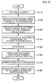
- FIG. 2 is a flow chart of a method of detouring an obstacle using an autonomous mobile robot according to an embodiment of the present invention
- FIG. 3 is a view for describing a process of calculating location information of a moving object according to an embodiment of the present invention
- FIG. 4 is a view showing an autonomous mobile robot and a user, a moving object, in a 2D space according to an embodiment of the present invention
- FIG. 5 is a view showing collision between an autonomous mobile robot and an obstacle when a user moves the autonomous mobile robot using a naviguide according to an embodiment of the present invention.
- FIG. 6 is a view for describing a method of detouring an obstacle to avoid collision occurring between the user and the autonomous mobile robot of FIG. 5 because of a moving time delay therebetween.
- FIG. 1 is a block diagram of an autonomous mobile robot capable of detouring an obstacle according to an embodiment of the present invention.
- the autonomous mobile robot includes a control unit 610, a storage unit 620, a drive unit 630, a location calculating unit 640, an extension unit 650, a route calculating unit 660, and an obstacle detecting unit 770.
- the extension unit 650 is connected to a moving object 690, and guides a movement of the autonomous mobile robot.
- the extension unit 650 in the present embodiment characteristically extends corresponding to a pulling force of the moving object 690.
- the moving object 690 in the present embodiment is a user.
- the control unit 610 controls an overall operation of the autonomous mobile robot. According to an embodiment of the present invention, the control unit 610 controls calculation of a route of the autonomous mobile robot led by the moving object 690, and a direction that the autonomous mobile robot moves when it encounters an obstacle.
- the storage unit 620 stores programs necessary for operations of the autonomous mobile robot. According to an embodiment of the present invention, the storage unit 620 stores a program necessary to calculate the route of the autonomous mobile robot and to detect presence of an obstacle.
- the drive unit 630 performs operations necessary for traveling of the autonomous mobile robot under control of the control unit 110.
- the control unit 610 controls the drive unit 630 such that the autonomous mobile robot moves in a direction corresponding to a direction that the moving object connected to the extension unit 650 moves.
- the location calculating unit 640 calculates a location of the moving object 690 on the basis of the length and direction that the extension unit 650 connected to the moving object 690 is pulled.
- the moving object 690 is a user.
- the location calculating unit 640 may employ a naviguide to obtain information about the length and direction that the extension unit 650 connected to the moving object 690 is pulled.
- the route calculating unit 660 calculates a route of the autonomous mobile robot on the basis of the location information of the moving object 690 calculated by the location calculating unit 640.
- the control unit 610 stores in the storage unit 620 the calculated route information based on the location information of the moving object 690.
- the obstacle detecting unit 670 detects an obstacle placed within a certain distance in a moving direction of the autonomous mobile robot while the autonomous mobile robot is being led by the moving object 690.
- the obstacle detecting unit 670 detects presence of an obstacle using a distance sensor mounted to the autonomous mobile robot.
- the control unit 610 controls the drive unit 630 such that the autonomous mobile robot ignores a move command made by pulling of the moving object 690, but travels on the basis of the stored route information.
- the autonomous mobile robot connected to the moving object manipulating a moving direction when moved to a desired location, the autonomous mobile robot does not collide with an obstacle, thereby preventing damage to a device. Also, since the autonomous mobile robot does not collide with a user, the user does not get hurt. Also, since the collision is prevented, the user can easily manipulate the movement of the autonomous mobile robot.
- FIG. 2 is a flow chart showing a method of detouring an obstacle using an autonomous mobile robot according to an embodiment of the present invention.
- control unit 610 inputs, to the drive unit 630, a move command for the autonomous mobile robot made as the moving object 690 pulls the extension unit 650 S 110. Accordingly, the autonomous mobile robot moves by being led by the moving object 690 connected through the extension unit 650 S120.
- the control unit 610 controls the location calculating unit 640 to calculate location information of the moving object 690 on the basis of the length and direction that the extension unit 650 extends S130. That is, the location calculating unit 640 obtains information on the length and direction that the extension unit 650 extends using a naviguide, and calculates the location information of the moving object 690 on the basis of the obtained information.
- control unit 610 controls the route calculating unit 660 to calculate a route of the autonomous mobile robot on the basis of the location information of the moving object 690 S140. Then, the control unit 610 stores the route information based on the calculated location information of the moving object 690 in the storage unit 620 S150.
- the control unit 610 controls the obstacle detecting unit 670 to detect an object placed within a predetermined distance in a moving direction while the autonomous mobile robot is moving by manipulation of the moving object 690 S 160.
- the control unit 610 When an obstacle is detected by the obstacle detecting unit 670, the control unit 610 extracts the route information of the moving object 690 from the storage unit 620, without following a move command received from the moving object 690 S170. Accordingly, the control unit 610 controls the drive unit 630 to move the autonomous mobile robot on the basis of the extracted route information S 180.
- FIG. 3 is a view for describing a process of calculating location information of the moving object according to an embodiment of the present invention.
- the location calculating unit 640 employs a naviguide. Since a specific structure and principle of the naviguide have been well known, the detailed description thereof will be omitted.
- the location calculating unit 640 detects and calculates an extension length (L) 140 and a direction ⁇ 130 of a rope (i.e., extension unit 650) pulled by the moving object 690 (user 110 in the drawing) using a provided naviguide 150, and provides information on the calculated length and distance to the control unit 610.
- L extension length
- ⁇ 130 of a rope i.e., extension unit 650
- the control unit 610 receives information on the length L and direction ⁇ that the extension unit 650 extends, and controls a moving speed and a moving direction of the autonomous robot, using the received data.
- the controller 610 expresses information on the distance L and direction ⁇ with respect to the moving object 110 into 2D spatial coordinates in an environment that the autonomous mobile robot moves.
- the naviguide 150 of the location calculating unit 640 is set to the origin (0, 0) of the 2D coordinates. Then, the 2D coordinates (x, y) of the user 110 can be easily obtained on the basis of the origin. Since the information on a length L 140 and a direction ⁇ 130 of the rope pulled by the user 110 has already been known, the location calculating unit 640 can express the location information of the user 110, which is calculated on the basis of the naviguide 150, as 2D coordinates (Lcos ⁇ , L sin ⁇ ).
- FIG. 4 is a view showing an autonomous mobile robot and a moving object, a user, on a 2D space according to an embodiment of the present invention.
- an X axis of an environment where an autonomous mobile robot 220 exists is Gx
- a Y axis is Gy.
- the absolute coordinates and a heading angle 260 of the autonomous mobile robot 220 moving on a space defined by the Gx axis and the Gy axis may be calculated using a positioning system installed in the space, and the odo-metry information of the autonomous mobile robot 220.
- the calculated 2D coordinates of the center of the autonomous mobile robot 220 are (Tx, Ty), and the heading angle is ⁇ 260.
- a state is illustrated where the rope connected to the naviguide of the location calculating unit 640 is pulled from a position distanced from the center (Tx, Ty) of the autonomous mobile robot 220 at a distance B 270.
- 2D coordinates (x, y) of the user on the space defined by the Gx axis and the Gy axis may be obtained using Equation 1 below.
- x y 1 cos ⁇ - sin ⁇ T x sin ⁇ cos ⁇ T y 0 0 1 ⁇ 1 0 B 0 1 0 0 0 1 ⁇ cos ⁇ - sin ⁇ L ⁇ cos ⁇ sin ⁇ cos ⁇ L ⁇ sin ⁇ 0 0 0
- FIG. 5 is an exemplary view showing collision between an autonomous mobile robot and an obstacle when a user moves the autonomous mobile robot using a naviguide according to an embodiment of the present invention.
- a user 320 moves an autonomous mobile robot 340 by pulling a rope connected to a naviguide of the location calculating unit 640. For this reason, a moving time delay between the user 320 and the autonomous mobile robot 340 occurs corresponding to an extension length of a rope connected to a naviguide.
- the autonomous mobile robot 350 has not yet detoured the obstacle 310.
- a move command of the naviguide controls the autonomous mobile robot 350 to move toward a current location of the user 330, collision between the obstacle 310 and the autonomous mobile robot 350 occurs. Therefore, the present invention can serve to address this problem caused by the moving time delay between the autonomous mobile robot 350 and the user 330.
- FIG. 6 is a view for describing a method of preventing collision between an obstacle and an autonomous mobile robot, which occurs due to the moving time delay between the user and the autonomous mobile robot of FIG. 5 .
- an embodiment of the present invention proposes a method of preventing collision between an obstacle and an autonomous robot 420 by a movement control command for an autonomous mobile robot 420 to follow a route 440 of a user 430.
- the autonomous mobile robot 420 may collide with the obstacle 410.
- the autonomous mobile robot 420 stores the route 440 of the user 430 while moving.
- the autonomous mobile robot 420 moves on the basis of the stored route information 440, thereby preventing the collision with the obstacle.
- the present invention may be applied to a field of an autonomous mobile robot that can move safely without colliding with an obstacle when following a moving object.
Landscapes
- Engineering & Computer Science (AREA)
- Physics & Mathematics (AREA)
- Aviation & Aerospace Engineering (AREA)
- Radar, Positioning & Navigation (AREA)
- Remote Sensing (AREA)
- General Physics & Mathematics (AREA)
- Automation & Control Theory (AREA)
- Robotics (AREA)
- Mechanical Engineering (AREA)
- Electromagnetism (AREA)
- Control Of Position, Course, Altitude, Or Attitude Of Moving Bodies (AREA)
- Manipulator (AREA)
Claims (7)
- Autonomer mobiler Roboter (420), umfassend: eine Verlängerungseinheit (650), die dazu ausgelegt ist, mit einem sich bewegenden Objekt (690) verbunden zu werden, und die sich im Verhältnis zu einer Zugkraft des sich bewegenden Objekts (690) verlängert;
eine Antriebseinheit (630), die den autonomen mobilen Roboter (420) entsprechend der Zugkraft des mit der Verlängerungseinheit (650) verbundenen Objekts in Richtung des sich bewegenden Objekt (690) bewegt;
eine Weginformationsbeschaffungseinheit, die Weginformationen gemäß einer Verlängerungslänge beschafft, bis zu der sich die Verlängerungseinheit (650) entsprechend der Zugkraft des sich bewegenden Objekts (690) verlängert;
eine Hindernisdetektionseinheit (670), die das Vorhandensein eines Hindernisses (410) detektiert, das innerhalb eines vorgegebenen Abstands in einer Bewegungsrichtung des autonomen mobilen Roboters (420) platziert ist, der durch das sich bewegende Objekt (690) geführt wird; und
eine Steuereinheit (610), die die Antriebseinheit (630) so steuert, dass sich der autonome mobile Roboter (420) basierend auf den Weginformationen entlang eines Weges bewegt,
wobei die Weginformationsbeschaffungseinheit umfaßt:eine Positionsberechnungseinheit (640), die Positionsinformationen des sich bewegenden Objekts (690) berechnet, das mit der Verlängerungseinheit (650) verbunden ist; undeine Wegberechnungseinheit (660), die einen Weg der Antriebseinheit (630) gemäß der Verlängerungslänge der Verlängerungseinheit (650) auf der Basis der berechneten Positionsinformationen des sich bewegenden Objekts (690) berechnet,wobei die Positionsberechnungseinheit (640) Positionsinformationen des sich bewegenden Objekts (690) unter Verwendung von Informationen bezüglich der Verlängerungslänge sowie der Richtung berechnet, in die sich die Verlängerungseinheit (650) entsprechend der Zugkraft des sich bewegenden Objekts (690) verlängert. - Autonomer mobiler Roboter (420) nach Anspruch 1, wobei die Positionsberechnungseinheit (640) die Informationen bezüglich der Verlängerungslänge sowie der Richtung der Verlängerungseinheit (650) unter Verwendung eines Navi-Guides beschafft.
- Autonomer mobiler Roboter (420) nach Anspruch 1, wobei die Hindernisdetektionseinheit (670) das Vorhandensein des Hindernisses (410) unter Verwendung eines Abstandssensors detektiert.
- Autonomer mobiler Roboter (420) nach Anspruch 1, ferner umfassend eine Speichereinheit (620), die die beschafften Weginformationen speichert,
wobei die Steuereinheit (610) eine Bewegung der Antriebseinheit (630) auf der Basis der in der Speichereinheit (620) gespeicherten Weginformationen steuert, wenn das Hindernis (410) vorhanden ist. - Verfahren zum Umgehen eines Hindernisses (410) für einen autonomen mobilen Roboter (420), wobei das Verfahren umfaßt:Bewegen des autonomen mobilen Roboters (420) in Richtung eines sich bewegenden Objekts (690), das mit einer Verlängerungseinheit (650) verbunden ist, die mit einem Hauptkörper verbunden ist, entsprechend einer Zugkraft des sich bewegenden Objekts (690); Beschaffen von Weginformationen gemäß einer Verlängerungslänge, bis zu der sich die Verlängerungseinheit (650) entsprechend der Zugkraft des sich bewegenden Objekts (690) verlängert; Detektieren des Vorhandenseins eines Hindernisses (410), das innerhalb eines vorgegebenen Abstands in einer Bewegungsrichtung des autonomen mobilen Roboters (420) platziert ist, der durch das sich bewegende Objekt (690) geführt wird; und Bewegen des autonomen mobilen Roboters (420) entlang eines Weges basierend auf den Weginformationen, wenn das Hindernis (410) existiert,wobei der Schritt des Beschaffens der Weginformationen umfaßt:Berechnen von Positionsinformationen des sich bewegenden Objekts (690), das mit der Verlängerungseinheit (650) verbunden ist; undBerechnen eines Weges des autonomen mobilen Roboters (420) entsprechend einer Verlängerungslänge der Verlängerungseinheit (650) auf der Basis der berechneten Positionsinformationen des sich bewegenden Objekts (690),wobei beim Schritt des Berechnens der Positionsinformationen die Positionsinformationen des sich bewegenden Objekts (690) unter Verwendung von Informationen bezüglich einer Verlängerungslänge sowie einer Richtung berechnet werden, in die sich die Verlängerungseinheit (650) entsprechend der Zugkraft des sich bewegenden Objekts (690) verlängert.
- Verfahren nach Anspruch 5, wobei beim Schritt des Berechnens der Positionsinformationen die Informationen bezüglich der Verlängerungslänge sowie der Richtung der Verlängerungseinheit (650) unter Verwendung eines Navi-Guides beschafft werden.
- Verfahren nach Anspruch 5, wobei beim Schritt des Detektierens des Vorhandenseins des Hindernisses (410) das Vorhandensein des Hindernisses (410) unter Verwendung eines Abstandssensors detektiert wird.
Applications Claiming Priority (2)
| Application Number | Priority Date | Filing Date | Title |
|---|---|---|---|
| KR1020060095050A KR100811886B1 (ko) | 2006-09-28 | 2006-09-28 | 장애물 회피 진행이 가능한 자율이동로봇 및 그 방법 |
| PCT/KR2007/000385 WO2008038865A1 (en) | 2006-09-28 | 2007-01-23 | Autonomous mobile robot capable of detouring obstacle and method thereof |
Publications (3)
| Publication Number | Publication Date |
|---|---|
| EP2083971A1 EP2083971A1 (de) | 2009-08-05 |
| EP2083971A4 EP2083971A4 (de) | 2009-11-04 |
| EP2083971B1 true EP2083971B1 (de) | 2011-12-21 |
Family
ID=39230286
Family Applications (1)
| Application Number | Title | Priority Date | Filing Date |
|---|---|---|---|
| EP07708566A Not-in-force EP2083971B1 (de) | 2006-09-28 | 2007-01-23 | Autonomer mobiler roboter, der hindernisse umgehen kann, und verfahren dafür |
Country Status (6)
| Country | Link |
|---|---|
| US (1) | US20100036556A1 (de) |
| EP (1) | EP2083971B1 (de) |
| JP (1) | JP2010505179A (de) |
| KR (1) | KR100811886B1 (de) |
| AT (1) | ATE537942T1 (de) |
| WO (1) | WO2008038865A1 (de) |
Families Citing this family (17)
| Publication number | Priority date | Publication date | Assignee | Title |
|---|---|---|---|---|
| US8275724B2 (en) * | 2008-10-15 | 2012-09-25 | The United States Of America As Represented By The Administrator Of The National Aeronautics And Space Administration | Method of improving system performance and survivability through changing function |
| US9171266B2 (en) * | 2008-10-15 | 2015-10-27 | The United States Of America As Represented By The Administrator Of The National Aeronautics And Space Administration | Power provision based on self-sacrificing craft |
| IL200921A (en) * | 2009-09-14 | 2016-05-31 | Israel Aerospace Ind Ltd | A robotic carry system for infantry and useful methods for the above purpose |
| KR101169674B1 (ko) * | 2010-03-11 | 2012-08-06 | 한국과학기술연구원 | 원격현전 로봇, 이를 포함하는 원격현전 시스템 및 이의 제어 방법 |
| TWM451103U (zh) * | 2012-10-30 | 2013-04-21 | Agait Technology Corp | 行走裝置 |
| US9623560B1 (en) * | 2014-11-26 | 2017-04-18 | Daniel Theobald | Methods of operating a mechanism and systems related therewith |
| KR101804770B1 (ko) | 2015-08-24 | 2017-12-05 | 주식회사 유진로봇 | 네비가이더, 네비가이더를 이용한 이동 로봇 및 이동 로봇의 가이드 방법 |
| CN107198499B (zh) * | 2016-03-18 | 2021-03-05 | 松下电器(美国)知识产权公司 | 自主移动装置、自主移动方法以及自主移动系统 |
| US11199852B2 (en) * | 2016-08-25 | 2021-12-14 | Lg Electronics Inc. | Mobile robot and control method for controlling the same |
| US20180079591A1 (en) * | 2016-09-19 | 2018-03-22 | Jackson State University | Automated trash cart |
| JP6943068B2 (ja) * | 2017-08-15 | 2021-09-29 | トヨタ自動車株式会社 | 経路探索装置、経路探索方法、及び経路探索プログラム |
| EP3610278A4 (de) * | 2018-02-20 | 2020-10-14 | Intelligent Cleaning Equipment Holdings Co., Ltd. | Verfolgungsvorrichtung, system zur verfolgung von objekten und zugehöriges verfahren zur verwendung |
| CN110653837B (zh) * | 2019-10-31 | 2021-08-13 | 灵动科技(北京)有限公司 | 自主移动装置及仓储物流系统 |
| KR102348607B1 (ko) | 2020-08-10 | 2022-01-07 | 조황 | 움직이는 물체와 동반하는 이동 로봇 시스템 및 그의 제어방법 |
| JP7409264B2 (ja) * | 2020-08-27 | 2024-01-09 | トヨタ自動車株式会社 | 運搬システム、運搬方法、及びプログラム |
| KR20220040801A (ko) | 2020-09-24 | 2022-03-31 | 한화디펜스 주식회사 | 이동체, 이동체의 제어 방법 및 이동체의 이동경로 제어 시스템 |
| KR102519131B1 (ko) | 2021-04-02 | 2023-04-10 | 한국전자기술연구원 | 태그 기반 로봇 제어기의 작업 궤적 생성 방법 및 장치 |
Family Cites Families (15)
| Publication number | Priority date | Publication date | Assignee | Title |
|---|---|---|---|---|
| JPS61245213A (ja) | 1985-04-23 | 1986-10-31 | Kajima Corp | 自走式ロボツト |
| JPH0542087A (ja) * | 1991-08-14 | 1993-02-23 | Matsushita Electric Ind Co Ltd | 自走式掃除機 |
| JPH06144247A (ja) * | 1992-11-16 | 1994-05-24 | Japan Aviation Electron Ind Ltd | ゴルフカート |
| JPH08166822A (ja) * | 1994-12-13 | 1996-06-25 | Nippon Telegr & Teleph Corp <Ntt> | ユーザ追尾型移動ロボット装置及びセンシング方法 |
| JPH08207850A (ja) * | 1995-02-03 | 1996-08-13 | Nikon Corp | 追従型制御装置 |
| JPH1016782A (ja) * | 1996-06-27 | 1998-01-20 | Nikon Corp | 移動装置 |
| JP3254152B2 (ja) * | 1996-12-10 | 2002-02-04 | 三菱重工業株式会社 | クレーンの荷役経路設定方法及びその装置 |
| JP3597418B2 (ja) * | 1999-07-28 | 2004-12-08 | 本田技研工業株式会社 | 隊列走行装置 |
| NL1014780C2 (nl) * | 2000-03-29 | 2001-02-20 | Idento Electronics Bv | Werkwijze en inrichting voor het melken van vee. |
| JP2003029842A (ja) * | 2002-04-08 | 2003-01-31 | Matsushita Electric Ind Co Ltd | 移動作業ロボット |
| WO2003096054A2 (en) * | 2002-05-10 | 2003-11-20 | Honda Giken Kogyo Kabushiki Kaisha | Real-time target tracking of an unpredictable target amid unknown obstacles |
| JP4316477B2 (ja) | 2004-11-18 | 2009-08-19 | パナソニック株式会社 | 移動ロボットの追従方法 |
| JP2006155349A (ja) * | 2004-11-30 | 2006-06-15 | Sony Corp | 追尾方法、追尾装置、追尾システム及び追尾プログラム |
| US20100222925A1 (en) * | 2004-12-03 | 2010-09-02 | Takashi Anezaki | Robot control apparatus |
| KR200381713Y1 (ko) | 2005-01-13 | 2005-04-14 | 주식회사 다진시스템 | 견인구조 |
-
2006
- 2006-09-28 KR KR1020060095050A patent/KR100811886B1/ko active Active
-
2007
- 2007-01-23 JP JP2009530241A patent/JP2010505179A/ja active Pending
- 2007-01-23 EP EP07708566A patent/EP2083971B1/de not_active Not-in-force
- 2007-01-23 US US12/443,381 patent/US20100036556A1/en not_active Abandoned
- 2007-01-23 WO PCT/KR2007/000385 patent/WO2008038865A1/en not_active Ceased
- 2007-01-23 AT AT07708566T patent/ATE537942T1/de active
Also Published As
| Publication number | Publication date |
|---|---|
| JP2010505179A (ja) | 2010-02-18 |
| EP2083971A4 (de) | 2009-11-04 |
| WO2008038865A1 (en) | 2008-04-03 |
| KR100811886B1 (ko) | 2008-03-10 |
| US20100036556A1 (en) | 2010-02-11 |
| EP2083971A1 (de) | 2009-08-05 |
| ATE537942T1 (de) | 2012-01-15 |
Similar Documents
| Publication | Publication Date | Title |
|---|---|---|
| US20100036556A1 (en) | Autonomous mobile robot capable of detouring obstacle and method thereof | |
| US10223916B2 (en) | Automated guided vehicle system based on autonomous mobile technique and a method for controlling the same | |
| US11987475B2 (en) | System and method for transporting a swaying hoisted load | |
| US9789612B2 (en) | Remotely operating a mobile robot | |
| US10960979B2 (en) | Systems and methods for positioning a hoist and hook | |
| JP5835254B2 (ja) | ロボットシステム、及び、ロボットシステムの制御方法 | |
| US9079307B2 (en) | Autonomous locomotion apparatus, autonomous locomotion method, and program for autonomous locomotion apparatus | |
| WO2020018527A1 (en) | Systems and methods for optimizing route planning for tight turns for robotic apparatuses | |
| US11597077B2 (en) | Cable suspended robot for industrial plants | |
| KR102235513B1 (ko) | 적어도 부분적으로 자율적으로 움직이는, 이동식 의료용 유닛을 동작시키기 위한 방법, 및 이동식 의료용 유닛 | |
| KR101812017B1 (ko) | 철탑 및 송변전시설물 점검용 로봇 시스템 | |
| US12012309B2 (en) | Intuitive control of lifting equipment | |
| Graf et al. | Dependable interaction with an intelligent home care robot | |
| JP2020030051A (ja) | 屋内クレーンの自動運転装置及び自動運転方法 | |
| US20260003371A1 (en) | Systems and Methods for an Autonomous Mobile Robot Fleet Coordination | |
| EP3958086A1 (de) | Verfahren und system zur verbesserung einer karte für einen roboter | |
| FI129250B (en) | Control system for controlling the machine tool | |
| JP2003140747A (ja) | 自律移動装置及び自律移動装置運用システム | |
| KR102777443B1 (ko) | 지하시설물 탐사를 위한 자율탐사 로봇 및 자율탐사 방법 | |
| Savkin et al. | A framework for safe assisted navigation of semi-autonomous vehicles among moving and steady obstacles | |
| EP4321955B1 (de) | Steuerung eines fahrerlosen transportfahrzeugs mit gabelstaplerfunktionen | |
| CN116774691A (zh) | 管制区域管理系统和方法、移动体管理系统及非暂时性存储介质 | |
| JP2008021178A (ja) | 自律移動ロボット、自律移動方法および自律移動情報処理プログラム | |
| WO2021082855A1 (zh) | 自主机器人及其及移动控制方法、装置和存储介质 | |
| Savkin et al. | A method for collision free assisted navigation of semi-autonomous vehicles in dynamic environments with moving and static obstacles |
Legal Events
| Date | Code | Title | Description |
|---|---|---|---|
| PUAI | Public reference made under article 153(3) epc to a published international application that has entered the european phase |
Free format text: ORIGINAL CODE: 0009012 |
|
| 17P | Request for examination filed |
Effective date: 20090428 |
|
| AK | Designated contracting states |
Kind code of ref document: A1 Designated state(s): AT BE BG CH CY CZ DE DK EE ES FI FR GB GR HU IE IS IT LI LT LU LV MC NL PL PT RO SE SI SK TR |
|
| A4 | Supplementary search report drawn up and despatched |
Effective date: 20091005 |
|
| RIC1 | Information provided on ipc code assigned before grant |
Ipc: G05D 1/02 20060101ALI20090929BHEP Ipc: B25J 9/10 20060101AFI20080422BHEP |
|
| DAX | Request for extension of the european patent (deleted) | ||
| 17Q | First examination report despatched |
Effective date: 20091215 |
|
| RIC1 | Information provided on ipc code assigned before grant |
Ipc: G05D 1/02 20060101ALI20110328BHEP Ipc: B25J 9/10 20060101AFI20110328BHEP |
|
| GRAP | Despatch of communication of intention to grant a patent |
Free format text: ORIGINAL CODE: EPIDOSNIGR1 |
|
| GRAS | Grant fee paid |
Free format text: ORIGINAL CODE: EPIDOSNIGR3 |
|
| GRAA | (expected) grant |
Free format text: ORIGINAL CODE: 0009210 |
|
| AK | Designated contracting states |
Kind code of ref document: B1 Designated state(s): AT BE BG CH CY CZ DE DK EE ES FI FR GB GR HU IE IS IT LI LT LU LV MC NL PL PT RO SE SI SK TR |
|
| REG | Reference to a national code |
Ref country code: GB Ref legal event code: FG4D |
|
| REG | Reference to a national code |
Ref country code: CH Ref legal event code: EP |
|
| REG | Reference to a national code |
Ref country code: AT Ref legal event code: REF Ref document number: 537942 Country of ref document: AT Kind code of ref document: T Effective date: 20120115 |
|
| REG | Reference to a national code |
Ref country code: IE Ref legal event code: FG4D |
|
| REG | Reference to a national code |
Ref country code: DE Ref legal event code: R096 Ref document number: 602007019494 Country of ref document: DE Effective date: 20120223 |
|
| REG | Reference to a national code |
Ref country code: NL Ref legal event code: VDEP Effective date: 20111221 |
|
| PG25 | Lapsed in a contracting state [announced via postgrant information from national office to epo] |
Ref country code: LT Free format text: LAPSE BECAUSE OF FAILURE TO SUBMIT A TRANSLATION OF THE DESCRIPTION OR TO PAY THE FEE WITHIN THE PRESCRIBED TIME-LIMIT Effective date: 20111221 |
|
| LTIE | Lt: invalidation of european patent or patent extension |
Effective date: 20111221 |
|
| PG25 | Lapsed in a contracting state [announced via postgrant information from national office to epo] |
Ref country code: GR Free format text: LAPSE BECAUSE OF FAILURE TO SUBMIT A TRANSLATION OF THE DESCRIPTION OR TO PAY THE FEE WITHIN THE PRESCRIBED TIME-LIMIT Effective date: 20120322 Ref country code: LV Free format text: LAPSE BECAUSE OF FAILURE TO SUBMIT A TRANSLATION OF THE DESCRIPTION OR TO PAY THE FEE WITHIN THE PRESCRIBED TIME-LIMIT Effective date: 20111221 Ref country code: NL Free format text: LAPSE BECAUSE OF FAILURE TO SUBMIT A TRANSLATION OF THE DESCRIPTION OR TO PAY THE FEE WITHIN THE PRESCRIBED TIME-LIMIT Effective date: 20111221 Ref country code: SI Free format text: LAPSE BECAUSE OF FAILURE TO SUBMIT A TRANSLATION OF THE DESCRIPTION OR TO PAY THE FEE WITHIN THE PRESCRIBED TIME-LIMIT Effective date: 20111221 Ref country code: SE Free format text: LAPSE BECAUSE OF FAILURE TO SUBMIT A TRANSLATION OF THE DESCRIPTION OR TO PAY THE FEE WITHIN THE PRESCRIBED TIME-LIMIT Effective date: 20111221 |
|
| PGFP | Annual fee paid to national office [announced via postgrant information from national office to epo] |
Ref country code: DE Payment date: 20120326 Year of fee payment: 6 |
|
| PG25 | Lapsed in a contracting state [announced via postgrant information from national office to epo] |
Ref country code: BE Free format text: LAPSE BECAUSE OF FAILURE TO SUBMIT A TRANSLATION OF THE DESCRIPTION OR TO PAY THE FEE WITHIN THE PRESCRIBED TIME-LIMIT Effective date: 20111221 Ref country code: CY Free format text: LAPSE BECAUSE OF FAILURE TO SUBMIT A TRANSLATION OF THE DESCRIPTION OR TO PAY THE FEE WITHIN THE PRESCRIBED TIME-LIMIT Effective date: 20111221 |
|
| PG25 | Lapsed in a contracting state [announced via postgrant information from national office to epo] |
Ref country code: EE Free format text: LAPSE BECAUSE OF FAILURE TO SUBMIT A TRANSLATION OF THE DESCRIPTION OR TO PAY THE FEE WITHIN THE PRESCRIBED TIME-LIMIT Effective date: 20111221 Ref country code: IS Free format text: LAPSE BECAUSE OF FAILURE TO SUBMIT A TRANSLATION OF THE DESCRIPTION OR TO PAY THE FEE WITHIN THE PRESCRIBED TIME-LIMIT Effective date: 20120421 Ref country code: SK Free format text: LAPSE BECAUSE OF FAILURE TO SUBMIT A TRANSLATION OF THE DESCRIPTION OR TO PAY THE FEE WITHIN THE PRESCRIBED TIME-LIMIT Effective date: 20111221 Ref country code: CZ Free format text: LAPSE BECAUSE OF FAILURE TO SUBMIT A TRANSLATION OF THE DESCRIPTION OR TO PAY THE FEE WITHIN THE PRESCRIBED TIME-LIMIT Effective date: 20111221 Ref country code: BG Free format text: LAPSE BECAUSE OF FAILURE TO SUBMIT A TRANSLATION OF THE DESCRIPTION OR TO PAY THE FEE WITHIN THE PRESCRIBED TIME-LIMIT Effective date: 20120321 |
|
| PG25 | Lapsed in a contracting state [announced via postgrant information from national office to epo] |
Ref country code: PT Free format text: LAPSE BECAUSE OF FAILURE TO SUBMIT A TRANSLATION OF THE DESCRIPTION OR TO PAY THE FEE WITHIN THE PRESCRIBED TIME-LIMIT Effective date: 20120423 Ref country code: PL Free format text: LAPSE BECAUSE OF FAILURE TO SUBMIT A TRANSLATION OF THE DESCRIPTION OR TO PAY THE FEE WITHIN THE PRESCRIBED TIME-LIMIT Effective date: 20111221 Ref country code: RO Free format text: LAPSE BECAUSE OF FAILURE TO SUBMIT A TRANSLATION OF THE DESCRIPTION OR TO PAY THE FEE WITHIN THE PRESCRIBED TIME-LIMIT Effective date: 20111221 Ref country code: MC Free format text: LAPSE BECAUSE OF NON-PAYMENT OF DUE FEES Effective date: 20120131 |
|
| REG | Reference to a national code |
Ref country code: CH Ref legal event code: PL |
|
| REG | Reference to a national code |
Ref country code: AT Ref legal event code: MK05 Ref document number: 537942 Country of ref document: AT Kind code of ref document: T Effective date: 20111221 |
|
| REG | Reference to a national code |
Ref country code: IE Ref legal event code: MM4A |
|
| PLBE | No opposition filed within time limit |
Free format text: ORIGINAL CODE: 0009261 |
|
| STAA | Information on the status of an ep patent application or granted ep patent |
Free format text: STATUS: NO OPPOSITION FILED WITHIN TIME LIMIT |
|
| PG25 | Lapsed in a contracting state [announced via postgrant information from national office to epo] |
Ref country code: DK Free format text: LAPSE BECAUSE OF FAILURE TO SUBMIT A TRANSLATION OF THE DESCRIPTION OR TO PAY THE FEE WITHIN THE PRESCRIBED TIME-LIMIT Effective date: 20111221 Ref country code: CH Free format text: LAPSE BECAUSE OF NON-PAYMENT OF DUE FEES Effective date: 20120131 Ref country code: LI Free format text: LAPSE BECAUSE OF NON-PAYMENT OF DUE FEES Effective date: 20120131 |
|
| REG | Reference to a national code |
Ref country code: FR Ref legal event code: ST Effective date: 20121019 |
|
| 26N | No opposition filed |
Effective date: 20120924 |
|
| GBPC | Gb: european patent ceased through non-payment of renewal fee |
Effective date: 20120321 |
|
| PG25 | Lapsed in a contracting state [announced via postgrant information from national office to epo] |
Ref country code: IT Free format text: LAPSE BECAUSE OF FAILURE TO SUBMIT A TRANSLATION OF THE DESCRIPTION OR TO PAY THE FEE WITHIN THE PRESCRIBED TIME-LIMIT Effective date: 20111221 |
|
| REG | Reference to a national code |
Ref country code: DE Ref legal event code: R097 Ref document number: 602007019494 Country of ref document: DE Effective date: 20120924 |
|
| PG25 | Lapsed in a contracting state [announced via postgrant information from national office to epo] |
Ref country code: GB Free format text: LAPSE BECAUSE OF NON-PAYMENT OF DUE FEES Effective date: 20120321 Ref country code: AT Free format text: LAPSE BECAUSE OF FAILURE TO SUBMIT A TRANSLATION OF THE DESCRIPTION OR TO PAY THE FEE WITHIN THE PRESCRIBED TIME-LIMIT Effective date: 20111221 Ref country code: FR Free format text: LAPSE BECAUSE OF NON-PAYMENT OF DUE FEES Effective date: 20120221 Ref country code: IE Free format text: LAPSE BECAUSE OF NON-PAYMENT OF DUE FEES Effective date: 20120123 |
|
| PG25 | Lapsed in a contracting state [announced via postgrant information from national office to epo] |
Ref country code: ES Free format text: LAPSE BECAUSE OF FAILURE TO SUBMIT A TRANSLATION OF THE DESCRIPTION OR TO PAY THE FEE WITHIN THE PRESCRIBED TIME-LIMIT Effective date: 20120401 |
|
| PG25 | Lapsed in a contracting state [announced via postgrant information from national office to epo] |
Ref country code: FI Free format text: LAPSE BECAUSE OF FAILURE TO SUBMIT A TRANSLATION OF THE DESCRIPTION OR TO PAY THE FEE WITHIN THE PRESCRIBED TIME-LIMIT Effective date: 20111221 |
|
| PG25 | Lapsed in a contracting state [announced via postgrant information from national office to epo] |
Ref country code: DE Free format text: LAPSE BECAUSE OF NON-PAYMENT OF DUE FEES Effective date: 20130801 |
|
| REG | Reference to a national code |
Ref country code: DE Ref legal event code: R119 Ref document number: 602007019494 Country of ref document: DE Effective date: 20130801 |
|
| PG25 | Lapsed in a contracting state [announced via postgrant information from national office to epo] |
Ref country code: TR Free format text: LAPSE BECAUSE OF FAILURE TO SUBMIT A TRANSLATION OF THE DESCRIPTION OR TO PAY THE FEE WITHIN THE PRESCRIBED TIME-LIMIT Effective date: 20111221 |
|
| PG25 | Lapsed in a contracting state [announced via postgrant information from national office to epo] |
Ref country code: LU Free format text: LAPSE BECAUSE OF NON-PAYMENT OF DUE FEES Effective date: 20120123 |
|
| PG25 | Lapsed in a contracting state [announced via postgrant information from national office to epo] |
Ref country code: HU Free format text: LAPSE BECAUSE OF FAILURE TO SUBMIT A TRANSLATION OF THE DESCRIPTION OR TO PAY THE FEE WITHIN THE PRESCRIBED TIME-LIMIT Effective date: 20070123 |