EP2081313A2 - Interferenzminderung durch Mithören - Google Patents
Interferenzminderung durch Mithören Download PDFInfo
- Publication number
- EP2081313A2 EP2081313A2 EP09150668A EP09150668A EP2081313A2 EP 2081313 A2 EP2081313 A2 EP 2081313A2 EP 09150668 A EP09150668 A EP 09150668A EP 09150668 A EP09150668 A EP 09150668A EP 2081313 A2 EP2081313 A2 EP 2081313A2
- Authority
- EP
- European Patent Office
- Prior art keywords
- packet
- signal
- station
- base station
- time slot
- Prior art date
- Legal status (The legal status is an assumption and is not a legal conclusion. Google has not performed a legal analysis and makes no representation as to the accuracy of the status listed.)
- Withdrawn
Links
- 230000000116 mitigating effect Effects 0.000 title claims description 19
- 230000005540 biological transmission Effects 0.000 claims abstract description 73
- 238000000034 method Methods 0.000 claims description 30
- 230000004044 response Effects 0.000 claims description 28
- 238000001514 detection method Methods 0.000 claims description 15
- 230000008569 process Effects 0.000 claims description 7
- 238000012804 iterative process Methods 0.000 claims description 3
- 238000010586 diagram Methods 0.000 description 14
- 230000006870 function Effects 0.000 description 10
- 230000015654 memory Effects 0.000 description 10
- 230000002452 interceptive effect Effects 0.000 description 5
- 238000004891 communication Methods 0.000 description 4
- 239000011159 matrix material Substances 0.000 description 4
- 230000002093 peripheral effect Effects 0.000 description 3
- 230000001172 regenerating effect Effects 0.000 description 3
- 238000012549 training Methods 0.000 description 3
- 235000008694 Humulus lupulus Nutrition 0.000 description 2
- 230000008859 change Effects 0.000 description 2
- 238000012937 correction Methods 0.000 description 2
- 230000010363 phase shift Effects 0.000 description 2
- 239000004065 semiconductor Substances 0.000 description 2
- 238000001228 spectrum Methods 0.000 description 2
- 230000006978 adaptation Effects 0.000 description 1
- 238000013475 authorization Methods 0.000 description 1
- 230000003139 buffering effect Effects 0.000 description 1
- 230000001413 cellular effect Effects 0.000 description 1
- 150000004770 chalcogenides Chemical class 0.000 description 1
- 238000010276 construction Methods 0.000 description 1
- 230000008878 coupling Effects 0.000 description 1
- 238000010168 coupling process Methods 0.000 description 1
- 238000005859 coupling reaction Methods 0.000 description 1
- 125000004122 cyclic group Chemical group 0.000 description 1
- 230000007423 decrease Effects 0.000 description 1
- 230000009365 direct transmission Effects 0.000 description 1
- 238000013467 fragmentation Methods 0.000 description 1
- 238000006062 fragmentation reaction Methods 0.000 description 1
- 230000007774 longterm Effects 0.000 description 1
- 238000013507 mapping Methods 0.000 description 1
- 239000000463 material Substances 0.000 description 1
- 238000012545 processing Methods 0.000 description 1
- 230000000717 retained effect Effects 0.000 description 1
Images




Classifications
-
- H—ELECTRICITY
- H04—ELECTRIC COMMUNICATION TECHNIQUE
- H04L—TRANSMISSION OF DIGITAL INFORMATION, e.g. TELEGRAPHIC COMMUNICATION
- H04L1/00—Arrangements for detecting or preventing errors in the information received
- H04L1/004—Arrangements for detecting or preventing errors in the information received by using forward error control
- H04L1/0045—Arrangements at the receiver end
-
- H—ELECTRICITY
- H04—ELECTRIC COMMUNICATION TECHNIQUE
- H04B—TRANSMISSION
- H04B1/00—Details of transmission systems, not covered by a single one of groups H04B3/00 - H04B13/00; Details of transmission systems not characterised by the medium used for transmission
- H04B1/69—Spread spectrum techniques
- H04B1/707—Spread spectrum techniques using direct sequence modulation
- H04B1/7097—Interference-related aspects
- H04B1/7103—Interference-related aspects the interference being multiple access interference
- H04B1/7107—Subtractive interference cancellation
-
- H—ELECTRICITY
- H04—ELECTRIC COMMUNICATION TECHNIQUE
- H04J—MULTIPLEX COMMUNICATION
- H04J11/00—Orthogonal multiplex systems, e.g. using WALSH codes
- H04J11/0023—Interference mitigation or co-ordination
- H04J11/0026—Interference mitigation or co-ordination of multi-user interference
- H04J11/0036—Interference mitigation or co-ordination of multi-user interference at the receiver
- H04J11/004—Interference mitigation or co-ordination of multi-user interference at the receiver using regenerative subtractive interference cancellation
-
- H—ELECTRICITY
- H04—ELECTRIC COMMUNICATION TECHNIQUE
- H04L—TRANSMISSION OF DIGITAL INFORMATION, e.g. TELEGRAPHIC COMMUNICATION
- H04L1/00—Arrangements for detecting or preventing errors in the information received
- H04L1/12—Arrangements for detecting or preventing errors in the information received by using return channel
- H04L1/16—Arrangements for detecting or preventing errors in the information received by using return channel in which the return channel carries supervisory signals, e.g. repetition request signals
- H04L1/18—Automatic repetition systems, e.g. Van Duuren systems
- H04L1/1812—Hybrid protocols; Hybrid automatic repeat request [HARQ]
-
- H—ELECTRICITY
- H04—ELECTRIC COMMUNICATION TECHNIQUE
- H04L—TRANSMISSION OF DIGITAL INFORMATION, e.g. TELEGRAPHIC COMMUNICATION
- H04L1/00—Arrangements for detecting or preventing errors in the information received
- H04L2001/0092—Error control systems characterised by the topology of the transmission link
- H04L2001/0093—Point-to-multipoint
-
- H—ELECTRICITY
- H04—ELECTRIC COMMUNICATION TECHNIQUE
- H04L—TRANSMISSION OF DIGITAL INFORMATION, e.g. TELEGRAPHIC COMMUNICATION
- H04L1/00—Arrangements for detecting or preventing errors in the information received
- H04L2001/0092—Error control systems characterised by the topology of the transmission link
- H04L2001/0097—Relays
Definitions
- stations disposed along the propagation path of a transmission may overhear the broadcast information even though the packet may not be addressed to the overhearing station. Such a situation may also occur, for example, in spatial multiplexing systems where transmissions may occur simultaneously among multiple stations in the same time slot and at the same frequency. However, such multiple transmissions may result in interference with intended transmissions by transmissions that are not intended for a given stations.
- utilization of relay transmissions is capable of increasing both the capacity and reliability of a wireless network.
- the base station in the downlink the base station sends a packet to the relay station, and the relay station then forwards the packet to the destination station in a later time slot.
- the relay station retransmits the packet, the retransmitted packet can create interference to the base station and prevents the base station from reliably receiving normal uplink data from another station in the same frequency and time location.
- Embodiments of the invention provide a method, comprising receiving a first packet intended for another station by overhearing the transmission of the first packet, decoding the first packet, receiving a second packet and a retransmission of the first packet as a total signal, subtracting the decoded first packet from the total signal to provide a resulting signal, and decoding the second packet from the resulting signal.
- the method further comprises performing one or more of an iterative process, a combining process, joint data detection, or channel estimation, or combinations thereof, to decode the second packet.
- the method further comprises storing the decoded first packet to be utilized in a subsequent time slot.
- the second packet being received via a relay transmission.
- the second packet being received via hybrid automatic repeat request transmission.
- the method further comprises transmitting an acknowledgement that the first packet was successfully decoded and able to be utilized for interference mitigation in a subsequent time slot.
- Embodiments of the invention also provide a method, comprising transmitting a first packet in a downlink time slot, receiving a second packet in an uplink time slot superimposed with the first packet received in the uplink time slot as a retransmission as a superimposed signal, estimating a channel response of the retransmission of the first packet, removing the retransmission of the first packet from the superimposed signal based at least in part on said estimating to provide a resulting signal, and detecting the second packet from the resulting signal.
- the method further comprises storing the first packet transmitted in the downlink time slot for use in interference mitigation in an uplink time slot.
- the retransmission of the first packet comprises a relay transmission.
- the retransmission of the first packet comprises a hybrid automatic repeat request (HARQ) transmission.
- HARQ hybrid automatic repeat request
- said receiving of the second packet and the retransmission of the first packet overlap in time or frequency, or combinations thereof.
- the method further comprises specifying one or more modulation parameters of a retransmission of the first packet, said estimating the channel response being based at least in part on the one or more modulation parameters.
- the method further comprises regenerating the retransmission of the first packet based at least in part on said estimating the channel response, and using the regenerated transmission in said removing.
- Embodiments of the invention further provide a method, comprising receiving a first packet in a first time slot, decoding the first packet, relaying the first packet to another relay station in a second time slot, receiving a relayed version of the first packet transmitted from the other relay station in the third time slot and a second packet in the third time slot as a total signal, subtracting the decoded first packet from the total signal to provide a resulting signal and decoding the second packet from the resulting signal.
- the method further comprises transmitting an acknowledgement that the first packet was successfully decoded and able to be utilized for interference mitigation in a subsequent time slot.
- the method further comprises storing the first packet for use in interference mitigation in a subsequent time slot.
- Embodiments of the invention further provide a mobile station, comprising a processor and a radio-frequency circuit coupled to said processor, wherein the processor is capable of receiving a first packet intended for another station by overhearing the broadcast of the first packet, decoding the first packet, receiving a second packet and a retransmission of the first packet as a total signal, subtracting the decoded first packet from the total signal to provide a resulting signal, and decoding the second packet from the resulting signal.
- the processor is further capable of storing the decoded first packet to be utilized in a subsequent time slot.
- the second packet being received via a relay transmission.
- the second packet being received via hybrid automatic repeat request transmission.
- the processor being further capable of transmitting an acknowledgement that the first packet was successfully decoded and able to be utilized for interference mitigation in a subsequent time slot.
- Embodiments of the invention still further provide a base station, comprising a processor and a radio-frequency circuit coupled to said processor, wherein the processor is capable of transmitting a first packet in a downlink time slot, receiving a second packet in an uplink time slot superimposed with the first packet received in the uplink time slot as a retransmission as a superimposed signal, estimating a channel response of the retransmission of the first packet, removing the retransmission of the first packet from the superimposed signal based at least in part on said estimating to provide a resulting signal, and detecting the second packet from the resulting signal.
- the processor being further capable of storing the first packet transmitted in the downlink time slot for use in interference mitigation in an uplink time slot.
- said receiving of the second packet and the retransmission of the first packet overlap in time or frequency, or combinations thereof.
- the processor being further capable of specifying one or more modulation parameters of a retransmission of the first packet, said estimating the channel response being based at least in part on the one or more modulation parameters.
- the processor being further capable of regenerating the retransmission of the first packet based at least in part on said estimating the channel response, and using the regenerated transmission in said removing.
- Coupled may mean that two or more elements are in direct physical and/or electrical contact.
- coupled may also mean that two or more elements may not be in direct contact with each other, but yet may still cooperate and/or interact with each other.
- “coupled” may mean that two or more elements do not contact each other but are indirectly joined together via another element or intermediate elements.
- “On,” “overlying,” and “over” may be used to indicate that two or more elements are in direct physical contact with each other. However, “over” may also mean that two or more elements are not in direct contact with each other. For example, “over” may mean that one element is above another element but not contact each other and may have another element or elements in between the two elements.
- the term “and/or” may mean “and”, it may mean “or”, it may mean “exclusive-or”, it may mean “one”, it may mean “some, but not all”, it may mean “neither", and/or it may mean “both”, although the scope of claimed subject matter is not limited in this respect.
- the terms “comprise” and “include,” along with their derivatives, may be used and are intended as synonyms for each other.
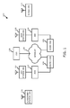
- network 100 may be an internet protocol (IP) type network comprising an internet 110 type network or the like that is capable of supporting mobile wireless access and/or fixed wireless access to internet 110.
- IP internet protocol
- network 100 may be in compliance with a Worldwide Interoperability for Microwave Access (WiMAX) standard or future generations of WiMAX, and in one particular embodiment may be in compliance with an Institute for Electrical and Electronics Engineers 802.16e standard (IEEE 802.16e).
- WiMAX Worldwide Interoperability for Microwave Access
- IEEE 802.16e Institute for Electrical and Electronics Engineers 802.16e standard
- network 100 may be in compliance with a Third Generation Partnership Project Long Term Evolution (3GPP LTE) or a 3GPP2 Air Interface Evolution (3GPP2 AIE) standard.
- network 100 may comprise any type of orthogonal frequency division multiple access (OFDMA) based wireless network, and the scope of the claimed subject matter is not limited in these respects.
- access service network (ASN) 112 is capable of coupling with base station (BS) 114 to provide wireless communication between subscriber station (SS) 116 and internet 110.
- Subscriber station 116 may comprise a mobile type device or information handling system capable of wirelessly communicating via network 100, for example a notebook type computer, a cellular telephone, a personal digital assistant, or the like.
- ASN 112 may implement profiles that are capable of defining the mapping of network functions to one or more physical entities on network 100.
- Base station 114 may comprise radio equipment to provide radio-frequency (RF) communication with subscriber station 116, and may comprise, for example, the physical layer (PHY) and media access control (MAC) layer equipment in compliance with an IEEE 802.16e type standard.
- Base station 114 may further comprise an IP backplane to couple to internet 110 via ASN 112, although the scope of the claimed subject matter is not limited in these respects.
- Network 100 may further comprise a visited connectivity service network (CSN) 124 capable of providing one or more network functions including but not limited to proxy and/or relay type functions, for example authentication, authorization and accounting (AAA) functions, dynamic host configuration protocol (DHCP) functions, or domain name service controls or the like, domain gateways such as public switched telephone network (PSTN) gateways or voice over internet protocol (VOIP) gateways, and/or internet protocol (IP) type server functions, or the like.
- AAA authentication, authorization and accounting
- DHCP dynamic host configuration protocol
- IP internet protocol
- these are merely example of the types of functions that are capable of being provided by visited CSN or home CSN 126, and the scope of the claimed subject matter is not limited in these respects.
- Visited CSN 124 may be referred to as a visited CSN in the case for example where visited CSN 124 is not part of the regular service provider of subscriber station 116, for example where subscriber station 116 is roaming away from its home CSN such as home CSN 126, or for example where network 100 is part of the regular service provider of subscriber station but where network 100 may be in another location or state that is not the main or home location of subscriber station 116.
- WiMAX type customer premises equipment (CPE) 122 may be located in a home or business to provide home or business customer broadband access to internet 110 via base station 120, ASN 118, and home CSN 126 in a manner similar to access by subscriber station 116 via base station 114, ASN 112, and visited CSN 124, a difference being that WiMAX CPE 122 is generally disposed in a stationary location, although it may be moved to different locations as needed, whereas subscriber station may be utilized at one or more locations if subscriber station 116 is within range of base station 114 for example.
- operation support system (OSS) 128 may be part of network 100 to provide management functions for network 100 and to provide interfaces between functional entities of network 100.
- Network 100 of FIG. 1 is merely one type of wireless network showing a certain number of the components of network 100, however the scope of the claimed subject matter is not limited in these respects.
- wireless network 100 may include base station 114 and subscriber station 116 as shown in and described with respect to FIG. 1 , and may further include destination station (DS) 212 and relay station (RS) 210.
- base station 114 broadcasts a first packet P1 as signal 214 to relay station 210 and also to a scheduled subscriber station 116 in a first time slot.
- Relay station 210 then forwards packet P1, labeled as packet P1', via signal 216 to destination station 212 in a second time slot.
- base station 114 sends data packet P2 via signal 218 to subscriber station 116.
- Such an arrangement is capable of increasing the spectrum efficiency via spatial multiplexing.
- the relayed P1 signal, packet P1' broadcast as signal 216 superimposes packet two's P2 signal 218 at subscriber station 116. Since subscriber station 116 has already received the data of packet P1 in the previous time slot, subscriber station 116 is capable of estimating the channel response between relay station 210 and subscriber station 116, and utilizes the channel response estimate to subtract the signal 216 of packet P1, relayed as P1', from the superimposed signal. Subscriber station 116 is then able to detect the desired packet P2 in signal 218.
- destination station 212 Because destination station 212 receives a relative weak version of signal 218 from base station 114, since destination station 212 is utilizing relay station 210, packet P2 signal 218 sent by base station 114 may cause little or no interference at destination station 212 for the reception of packet P1 in the second frame compared with the packet P1' via signal 216 from relay station 210.
- Such an arrangement may be generalized to multihop systems as shown in FIG. 3 , below, and/or to hybrid automatic repeat request (HARQ) type systems as shown in FIG. 4 , below.
- HARQ hybrid automatic repeat request
- the interference signal 216 may be subtracted from the received signal, signal 218, for signal enhancement.
- subscriber station 116 when receiving superimposed signals comprising the desired signal, signal 218, and the interfering signal, signal 216, subscriber station 116 is capable of estimating the channel response of the interfering signal, signal 216, using the known data based on receiving packet P1 via signal 214 in the previous frame by "overhearing" signal 214 in the first frame even though packet P1 is not intended for subscriber station 116, reconstructing the interfering signal, and then subtracting the interfering signal, signal 216, from the superimposed signal.
- subscriber station 116 is capable of detecting the desired signal, signal 218, as if there were no interference from signal 216.
- Wireless network 100 is capable of implementing such an overhearing, estimation, and cancellation technique to increase capacity.
- subscriber stations disposed near base station 114 may overhear signals broadcast to other stations.
- the overheard signal may be utilized by such nearby subscriber stations to cancel interference that may be generated in a subsequent frame in the event the data in the overheard signal is sent again, for example if relayed by one or more relay stations 210, becoming interference.
- Such data retransmission may also occur in HARQ type systems.
- interference cancellation may be conducted at one or more subscriber stations 116 where one or more relay stations 210 are utilized to forward downlink packets received from base station 114 to one or more destination stations 212.
- base station 114 sends packet P1 to relay station 210 via signal 214.
- the intended final destination of packet P1 is destination station 212.
- Packet P1 broadcast as signal 214 is overheard by subscriber station 116 disposed in the vicinity of base station 114.
- Subscriber station 116 then decodes packet P1 and is capable of cancelling the interference related to the retransmission of packet P1 as packet P1' sent by relay station 210 in the next time slot as signal 216.
- Subscriber station 116 may acknowledge to base station 114 the successful decoding of packet P1. Such an acknowledgement may assist with scheduling at base station 114. For example, base station 114 may designate one or multiple subscriber stations 116 for overhearing. Base station 114 may then select one or more subscriber stations 116 as the next station to receive an intended packet from those subscriber stations 116 that acknowledged to base station 114 the successful decoding of overheard packets.
- base station 114 schedules that relay station 210 may forward packet P1 to destination station 212 in the next time slot, and base station 114 may simultaneously send packet P2 to subscriber station 116 in the next time slot.
- relay station 210 transmits a relay packet P1', the relayed version of packet P1, to destination station 212 via signal 216, and base station 114 transmits packet P2 to subscriber station 116 via signal 218.
- the relay station may extract the information bits of the packets received from base station 114 and generate new packets using the same information bits. For example, fragmentation may be applied at relay station 210. As long as the information bits are overheard by subscriber station 116, the interference cancellation can be applied. As a result of simultaneous transmission of packet P1 and relay packet P1', signal 218 and signal 216 are superimposed as a signal received by subscriber station 116.
- FEC forward error correction
- subscriber station 116 Since subscriber station has previously received information about P1 from signal 214, subscriber station 116 estimates the channel response over the link from relay station 210 to subscriber station 116 using the information in packet P1, computes packet P1' using the decoded information and channel response, and then subtracts the interference of signal 216 from the superimposed received signal. Subscriber station is then capable of decoding packet P2 after the interference signal 216 is sufficiently reduced or removed from the superimposed received signal. Signal 216 and signal 218 may likewise superimpose in the signal received at destination station 212. However, the link from relay station 210 to destination station 212 may have a better quality than the link from base station 114 to destination station 212 when relay station 210 is utilized by base station 114 via base station routing and scheduling.
- any interference from signal 218 is relatively weak with respect to signal 216, and does not impact the ability of destination station 212 to decode packet P1' from signal 216.
- Such an arrangement of relative weakness of signal 218 with respect to signal 216 may be facilitated via power control at relay station 210 and/or base station 114 in addition to control via routing and scheduling.
- destination station 212 is capable of decoding packet P1' from signal 216 broadcast by relay station 210, although the scope of the claimed subject matter is not limited in this respect.
- a multihop relay arrangement of wireless network is shown in and described with respect to FIG. 3 , below.
- the signals in the first and second time slots may not overlap in frequency but the signals in the second time slot T2 at least partially overlap in frequency. The frequency overlapping causes the interference.
- the scheme depicted above employs one-shot hard detection and cancellation. Namely, subscriber station 216 decodes the information bits in packet P1 and quantizes the decoded information into binary bits. The bits may then employed as pilots in estimating the channel from relay station 210 to subscriber station 116. After the channel is estimated, the bits are employed to regenerate packet P1' and the signal of P1' is convolved with the estimated channel to reconstruct the interference. The reconstructed interference is removed from the superimposed signal in time slot T2 at subscriber station 116. Finally, the desired packet P2 may be decoded.
- This sequential one-shot process may provide lower complexity in computation and storage. Such a one-shot process may further implement soft cancellation and/or the joint data detection of P1 and P2.
- the joint data detection and/or channel estimation over the channels and signals on 214, 216, and 218 may be utilized to achieve an optimal performance at higher complexities, although the scope of the claimed subject matter is not limited in these respects
- soft cancellation may exploit the likelihood information obtained from the interference.
- the signal 216 may utilize binary phase-shift keying (BPSK).
- Node 116 computes the likelihood about a codebit in 216 from the overheard 214.
- the likelihood indicates that the codebit symbol is to be +1 with probability 0.7 and -1 with probability 0.3.
- the codebit symbol may be quantized to +1 when hard detection and cancellation are employed. Therefore, some information may be lost and errors may be generated because the true -1 may be converted to +1 with probability 0.3.
- joint detection may involve iterative decoding of P1 and P2, for example as used in Turbo code decoding, multiuser detection, and/or multiple-input, multiple-output (MIMO) decoding.
- Log-likelihood ratios of codebits or coded symbols may be exchanged among decoding processes.
- Joint detection may be utilized if P1 can not be correctly decoded in time slot T1.
- the joint data detection and channel estimation may be implemented where channel estimation and channel code decoding may help each other iteratively.
- subscriber station 216 may decode P1 in T1 and have knowledge that the decoding is not successful because the cyclic redundancy check (CRC) check may not pass.
- CRC cyclic redundancy check
- Subscriber station 216 may store the received signal of P1 for an iterative process.
- the decoded bits with errors may be treated as the true bits and utilized to regenerate transmitted signal of P1'.
- the regenerated signal may be utilized as channel training symbols to estimate the channel response from relay station 210 to subscriber station 116. Although the regenerated signal may have errors, the power of errors may be relatively small compared to the power of the regenerated signal. Therefore, the regenerated signal may still be useful. Interference cancellation may be conducted using the estimated channel and regenerated signal. Packet P2 may then decoded. If the decoding is successful, for example the CRC check is passed, the process stop at that point.
- the decoded bits of packet P2 may be exploited to facilitate the decoding of P1, which in turn facilitates back the decoding of P2.
- the decoded bits of P2 may be treated as the true bits to regenerate the transmitted signal of P2, and the received signal of P2 may be generated using the regenerated signal and the estimated channel response from base station 218 and subscriber station 116.
- the received signal of P2 may then be removed from the superimposed signals of 218 and 216.
- the remaining signal and the stored signal of 214 may be jointly utilized to decode the data in P1 and P1', which share the same information bits.
- the decoded information bits of P1 may then be used in channel estimation and interference cancellation for P2 iteratively, although the scope of the claimed subject matter is not limited in these respects.
- node 216 may combine the signals 214 and the superimposed signal received in time slot T2 to enhance the decoding of the information bits in P1 and/or P1' as follows. If the initial decoding of P1 using 214 fails, the log-likelihood ratios of the codebits of P1 are stored. The decoded information bits may be treated as the true bits and used in estimating channel response in 216. After the channel is estimated, log-likelihood ratios of the codebits of P1's may be computed. The log-likelihood ratios of the corresponding codebit in P1 and P1' are combined, for example added together. The combined log-likelihood ratios may then used to decode the information bits in P1 again.
- the combining enhances the decoding of P1.
- the received information may still be utilized for soft-cancellation and/or joint detection with additional complexities.
- Such techniques may be implemented in one or more embodiments, and may mitigate and/or remove the need of correct overhearing, however the scope of the claimed subject matter is not limited in these respects.
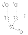
- FIG. 3 a diagram of a wireless network illustrating interference cancellation over a multihop relay in accordance with one or more embodiments will be discussed.
- relay arrangement of wireless network 100 utilizing overhearing as shown in FIG. 2 is capable of being extended to a multihop relay channel where multiple simultaneous relay transmissions may be utilized.
- base station 114 operates as a source node and transmits a packet that is sequentially forwarded to destination station 212 via multiple relay stations such as a first relay station (RS1) 310 and a second relay station (RS2) 312 as shown in FIG. 3 .
- RS1 first relay station
- RS2 second relay station
- the notation P i (t) denotes the i-th packet sent at time slot t.
- the transmitted signals of P i (t) and P i (t+n), where n is an integer, may be different, for example in terms of modulation and/or coding, while at least part of the information in the packets is the same. In the example shown in FIG.
- base station 114 transmits two packets, P 1 and P 2 , to destination station 212 and one packet, P 3 , to subscriber station 116 in two time slots. It is assumed that P 1 is already in relay station two 312 due to the previous transmissions.
- Relay station one 310 and relay station two 312 forward packet P 1 and packet P 2 sequentially as BS ⁇ RS1 ⁇ RS2 ⁇ DS.
- relay station one 310 and relay station two 312 buffer the data of the received or forwarded packet for interference cancellation.
- base station 114 transmits a new packet P 2 to relay station one 310 via signal 314.
- Relay station two 312 sends an older packet P 1 to destination station 212 via signal 318, as the data of P 1 was received at relay station two 312 in a previous time slot and stored in relay station two 312.
- the two transmissions of signals 314 and 318 spatially overlap to increase spectrum efficiency.
- Destination station 212 receives superimposed signals 314 and 318 received from base station 114 and relay station two 312, respectively. Both signals may contain useful information for destination station 212. Destination station 212 may not be able to correctly decode packet P 2 (1) for the following reason.
- the link between base station 114 and relay station one 310 may have a relatively higher quality and the information rate in packet signal 314 may be higher than the capacity of the link between base station 114 and destination station 212.
- an efficient decoding strategy for destination station to be able to decode packet P 2 (1) may be as follows. Destination station 212 decodes packet P 1 (1) transmitted by relay station two 312 over a higher quality channel between relay station two 312 and destination station 212, and treating signal 314 as interference. After P 1 (1) is decoded, signal 318 may be subtracted from the superimposed signal received by destination station 212 to arrive at signal 314. Thus, packet P 2 (1) may be obtained from signal 314 and stored for signal combining in the detection of a signal carrying packet P 2 (1) in time slot 3.
- destination station 212 may not want to store the signal having packet P 2 (1).
- Base station 114 may want to minimize the interference of P 2 (1) at destination station 212 using multihop relays. As the number of hops increases, the interference power from base station 114 to the destination station 212 decreases, although the scope of the claimed subject matter is not limited in this respect.
- relay station 310 In time slot 1, relay station 310 also receives superimposed signals 314 and 318 from base station 114 and relay station two 312, respectively. Since relay station one 310 has previously received the data of packet P 1 (1) from base station 114, decoded packet P 1 (1) and forwarded it to relay station two 312, relay station one 310 is capable of subtracting P 1 (1) from its total received signal. Signal 314 of packet P 2 (1) is thereby obtained, and relay station one 310 is capable of decoding packet P 2 (1).
- subscriber station 116 receives signal 314 and decodes packet P 2 (1) for interference mitigation in the next coming time slot. Such reception of signal 314 may be designated and scheduled by base station 114, and then subscriber station 116 may acknowledge to base station 114 if subscriber station 116 successfully decodes packet P 2 (1).
- relay station one 310 forwards the received data in packet P 2 (1) to relay station two 312 using signal 316 to transmit packet P 2 (2).
- base station 114 transmits data packet P 3 (2) to subscriber station 116 via signal 320.
- Relay station two 312 receives signal 320 as interference from base station 114. Since the packet P 3 (2) has not been previously decoded by relay station two 312, no interference cancellation will be applied. To account for such a situation, base station 114 may select relay station two 312 whose interference from base station 114 is relatively small.
- relay station one 310 may have a better channel to relay station two 312 than the channel from base station 114 to relay station two 312, RS2 can decode packet P 2 (2) via signal 316 received from relay station one 310 by treating signal 320 from base station 114 as interference.
- wireless network 100 may be extended to any number of relay hops, and the scope of the claimed subject matter is not limited in this respect.
- wireless network may be capable of interference mitigation via overhearing where retransmissions may occur, for example in a HARQ type system as discussed with respect to FIG. 4 , below.
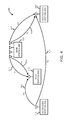
- FIG. 4 a diagram of a wireless network illustrating interference between a hybrid automatic repeat request (HARQ) transmission and a relay uplink transmission in accordance with one or more embodiments will be discussed.
- Interference cancellation via overhearing as shown in and described with respect to FIG. 2 and/or FIG. 3 likewise may be utilized in conjunction with a HARQ type system since the HARQ retransmissions contain the information known to the stations in the vicinity of the transmitter.
- An example of such a HARQ system is shown in FIG. 4 where relay station 210 forwards uplink packets received from subscriber station 116.
- base station 114 transmits packet P1 to destination station 212 via signal 410.
- Signal 410 is overheard by relay station 210 since relay station 210 is located in the vicinity of base station 114.
- relay station 210 may decode packet P1 and thereby have the capability to cancel any interference from retransmission of packet P1 in subsequent time slots.
- base station 114 transmits packet P1' to destination station 212 via signal 412 where packet P1' is computed from the data of packet P1, and where P1' may contain additional code bits of a forward error correction (FEC) codeword in P1.
- FEC forward error correction
- relay station 210 acknowledges to base station 114 that packet P1 is correctly received and decoded, base station 114 knows that relay station 210 is capable of cancelling interference resulting from signal 412, and schedules relay station 210 to receive packet P2 from subscriber station 116 via signal 414 in the uplink.
- Such an transmission of packet P2 may be an uplink relay packet sent by subscriber station 116 that may be disposed relatively far from base station 114 so that relay station 210 may be utilized as a relay between subscriber station 116 and base station 114.
- relay station 210 receives packet P2 from subscriber station 116 via signal 414, and also receives signal 412 from the HARQ transmission of packet P1' from base station 114 as interference. Since relay station 210 correctly received packet P1 in a previous time slot, relay station 210 is capable of computing P1', subtracting the interference of P1' from the total received signal, and then decoding P2. It should be noted that the example shown in FIG. 4 is merely one example of interference mitigation via overhearing in a wireless network 100 where retransmissions may be utilized such as in a HARQ type system, and the scope of the claimed subject matter is not limited in this respect.
- the station that correctly overheard a packet may acknowledge the reception of such an overheard packet to base station 114.
- Acknowledgment of the overheard packet by the stations is capable of assisting base station 114 with scheduling of subsequent transmissions with ability to implement spatial multiplexing.
- base station 114 may designate one or more stations to receive a transmission, even though the transmission may be destined for only one or a certain number of the stations and the other stations may receive the transmitted packet for purposes of interference mitigation and/or cancellation in a subsequently occurring time slot.
- the station conducting interference cancellation in the schemes described, above optionally may utilize linear techniques such as minimum mean square error (MMSE) and/or zero-forcing to null out interference which may be implemented at a lower complexity.
- MMSE minimum mean square error
- the station may learn the channel response of the interference and form a null pointing to the interference direction so that detecting and/or buffering of an interference packet may not be required, although the scope of the claimed subject matter is not limited in this respect.
- interference mitigation via overhearing may be implemented from the base station 114. Since base station 114 knows the relay data transmitted by relay station 210, base station 114 may treat the relay signal as channel training symbols, and use the symbols to estimate the interference channel response. After obtaining the channel response, interference from relay station 210 may be removed from the signal received at base station 114, and the uplink signal may be detected. Such an arrangement may be implemented as shown in FIG. 5 as follows.
- Base station 114 first transmits downlink data D1 via signal 512 to relay station 210 in time slot 1 in downlink subframe 518, and then relay station 210 forwards the downlink data D1 to destination station 212 in a later time slot, time slot 2, for example in uplink subframe 524.
- Relay station 210 may be utilized, for example where direct transmissions from base station 114 to destination station 212 may be impeded by on obstacle 510.
- Relay station 210 may comprise, for example, a subscriber station or a relay base station.
- the relay transmission in time slot 2 is scheduled in a normal uplink subframe 524, where uplink transmission from another subscriber station may occur.
- the uplink transmission may be interfered with by the relay transmission when the transmissions are in the same frequency-time location.
- D1 is the initial downlink transmission to relay station 210
- uplink data U1 514 is the relay transmission by relay station 210 via signal 514
- uplink data U2 516 is the normal uplink transmission from subscriber station 116 via signal 516 in uplink subframe 524.
- Downlink maps 526 and 530 are used to define access to downlink information.
- uplink maps 528 and 532 allocate access to the uplink channels.
- the relay transmission from signal 514 causes interference at base station 114 because base station 114 is only interested in receiving the uplink transmission from subscriber station 116 but not the relay transmission from relay station 210.
- Base station 114 is capable of cancelling the interference from the relay transmission as discussed herein.
- base station 114 may utilize a linear detector such as minimum mean square error (MMSE) and/or zero-forcing to cancel the interference from relay station 210, which may be similar to the reception in uplink spatial-division multiple access (SDMA).
- MMSE minimum mean square error
- SDMA uplink spatial-division multiple access
- interference cancellation may be implemented via a non-linear technique.
- the data in the relay transmission is already known at base station 114 because the data was previously transmitted by base station 114 in a former time slot. If base station 114 also knows the transmission parameters such as modulation and/or coding scheme and the channel response from relay station 210 to base station 114, base station 114 may be capable of at least partially or completely regenerating the interference signal caused by the transmission of relay data U1 and cancel the interference from the relay signal.
- a scheme for implementing such cancellation may be as follows.
- Base station 114 specifies the transmission parameters, for example modulation and/or coding scheme, power level, space-time coding, spatial multiplexing, frequency-time location, and so on, for the relay transmission. Base station 114 then estimates the channel response between relay station 210 and base station 114. Since the transmission parameters and data are already known at base station 114, the relayed frame, packet and/or symbols may be treated as a channel training signal with known data, which may result in increased channel estimation accuracy by a factor of six even under the interference from the normal uplink transmission. If some transmission parameters are unknown at base station 114, base station 114 still may estimate the channel response as follows.
- base station 114 may step through the possible parameters if some parameter of the relay such as modulation order is unknown at base station 114. For example, if the modulation order is unknown, base station 114 may assume that the modulation order is quadrature phase-shift keying (QPSK), 16 quadrature amplitude modulation (QAM), or 64 QAM, respectively, and then may estimate the channel response, respectively. One of the three resulting channel estimates may result in a maximum, or near maximum, in the likelihood function of the channel response, and base station 114 may select that channel response and the corresponding modulation order for the next step.
- QPSK quadrature phase-shift keying
- QAM quadrature amplitude modulation
- 64 QAM 64 QAM
- base station 114 may estimate the channel response over a set of unknown parameters and then select a channel estimate that results in a maximum, or near maximum, in the likelihood function of channel response. Base station 114 then regenerates the relay signal from the estimated channel response and reconstructed transmitted signal that is computed from the known data and transmission parameters. Base station 114 then subtracts the relay signal from the received signal, and then base station 114 detects the normal uplink signal 516 from the canceled interference signal, and the uplink data U2 may be decoded from uplink signal 516.
- relay station 210 is fully controlled by base station 114 so that base station 114 knows exactly the transmission parameters and does not need to estimate the transmission parameters, and thereby reducing complexity.
- relay signals transmitted by relay station 210 may be treated as instructed transmission, and the relay scheme may be referred to as instructed relay.
- Base station 114 may be considered to extend its radio to relay station, and/or to borrow the radio transmitter of relay station 210, although the scope of the claimed subject matter is not limited in this respect.
- the subscriber station 116 for example as shown in Fig. 2 , 3 , 4 , and 5 need not be limited to be a subscriber station. Instead, subscriber station 116 may be replaced by a relay station in some embodiments.
- network 600 of FIG. 6 there is one base station , two relay stations (RS1) 612 and (RS2) 614, and three subscriber stations (SS1) 616, (SS2) 618, and (SS3) 620.
- the three subscriber stations 616, 618, and 620 may be served by base station 610 and the two relay stations 612 and 614, respectively.
- Each of the relay stations 612 and/r 614 is capable of performing the interference mitigation in receiving data from base station 610, and base station 610 is capable of conducting interference mitigation in receiving data from each of the relay stations 612 and/or 614.
- base station 610 may sends a packet P1 to relay station 612 in a first time slot, which may be overheard by relay station 614.
- relay station 614 sends a second packet P2 to base station 610, and relay station 612 may forward packet P1' to subscriber station 616.
- Base station 610 can cancel interference of P1'.
- Relay station 612 and relay station 614 can overhear each other's data transmitted by base station 610, and each relay station 612 and/or 614 is capable of canceling interference caused by the relay transmission by the other relay transmission while receiving data from base station 610 and/or or its client station, for example subscriber station 616 of relay station 612 and/or subscriber station 620 of relay station 614.
- network 600 is an example of one implementation of interference mitigation by overhearing wherein various other arrangements may likewise be implemented, and the scope of the claimed subject matter is not limited in this respect.
- the estimation by base station 114 of the interfering channel from relay station 210 to base station 114 should be sufficiently accurate to achieve successful cancellation of the relay signal.
- the estimation may be subject to interference from normal uplink transmission and/or noise.
- the accuracy of the estimation may also depend on the channel variation rate.
- Base station 114 may control the power level of the uplink transmission to facilitate the channel estimation.
- y is the received signal vector
- H r is the channel matrix between the relay and the base station
- H u is the channel matrix between the uplink station and the base station
- d r is the transmitted relay signal vector
- d u is the transmitted uplink signal vector
- n is the noise vector.
- Axis 710 represents information rate in H r and axis 712 represents information rate in d u .
- Channel matrix d r is known and H r is the unknown under estimation.
- the combined vector, H u d u + n is treated as one noise vector with a certain covariance matrix.
- the accuracy of H r can be estimated for a given channel estimation scheme or be bounded by the Cramer-Rao lower bound.
- Base station 114 can control the power level of d u to achieve targeted estimation accuracy.
- the signal model of the above equation may be referred to as the multiple access channel (MAC), where H r and H u are assumed known and d r and d u are unknown of interest.
- the achievable data rate pair of d r and d u forms a pentagon region.
- achievable region of H r and d u may be computable by assuming d r and H u are assumed known and H r and d u are unknown of interest.
- the channel H r varies too fast or d u contains too much data, the detection of the desired data d u cannot be successful even with the most complex joint detection, which is illustrated in FIG. 7 .
- the uplink data rate is maximized at the 714, where the simple cancellation scheme above achieves the maximum rate. If the channel varies fast, that is H r contains higher information rate than r 0 716, then the achievable data rate d u may reduced from the maximum at the red bar.
- Base station 114 may schedule the rate d u through link adaptation according to the rate of H r . Since it is assumed in FIG. 7 that H r is Gaussian and optimally coded, the MAC model may provide an upper bound estimate, although the scope of the claimed subject matter is not limited in this respect.
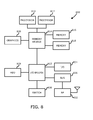
- Information handling system 800 of FIG. 8 may tangibly embody one or more of any of the network elements of network 100 as shown in and described with respect to FIG. 1 through FIG. 6 .
- information handling system 700 may represent the hardware of base station 114, subscriber station 116, and/or one or more of relay stations 210, 310, 312, and/or destination station 212, with greater or fewer components depending on the hardware specifications of the particular device or network element.
- information handling system 800 represents one example of several types of computing platforms, information handling system 800 may include more or fewer elements and/or different arrangements of elements than shown in FIG. 8 , and the scope of the claimed subject matter is not limited in these respects.
- Information handling system 800 may comprise one or more processors such as processor 810 and/or processor 812, which may comprise one or more processing cores.
- processor 810 and/or processor 812 may couple to one or more memories 816 and/or 818 via memory bridge 814, which may be disposed external to processors 810 and/or 812, or alternatively at least partially disposed within one or more of processors 810 and/or 812.
- Memory 816 and/or memory 818 may comprise various types of semiconductor based memory, for example volatile type memory and/or non-volatile type memory.
- Memory bridge 814 may couple to a graphics system 820 to drive a display device (not shown) coupled to information handling system 800.
- Information handling system 800 may further comprise input/output (I/O) bridge 822 to couple to various types of I/O systems.
- I/O system 824 may comprise, for example, a universal serial bus (USB) type system, an IEEE 1394 type system, or the like, to couple one or more peripheral devices to information handling system 800.
- Bus system 826 may comprise one or more bus systems such as a peripheral component interconnect (PCI) express type bus or the like, to connect one or more peripheral devices to information handling system 800.
- a hard disk drive (HDD) controller system 828 may couple one or more hard disk drives or the like to information handling system, for example Serial ATA type drives or the like, or alternatively a semiconductor based drive comprising flash memory, phase change, and/or chalcogenide type memory or the like.
- Switch 830 may be utilized to couple one or more switched devices to I/O bridge 822, for example Gigabit Ethernet type devices or the like.
- information handling system 500 may include a radio-frequency (RF) block 832 comprising RF circuits and devices for wireless communication with other wireless communication devices and/or via wireless networks such as network 100 of FIG. 1 , for example where information handling system 800 embodies base station 114 and/or subscriber station 116, although the scope of the claimed subject matter is not limited in this respect.
- RF radio-frequency
Landscapes
- Engineering & Computer Science (AREA)
- Computer Networks & Wireless Communication (AREA)
- Signal Processing (AREA)
- Mobile Radio Communication Systems (AREA)
- Radio Relay Systems (AREA)
Applications Claiming Priority (1)
| Application Number | Priority Date | Filing Date | Title |
|---|---|---|---|
| US12/016,609 US8861423B2 (en) | 2008-01-18 | 2008-01-18 | Interference mitigation by overhearing |
Publications (2)
| Publication Number | Publication Date |
|---|---|
| EP2081313A2 true EP2081313A2 (de) | 2009-07-22 |
| EP2081313A3 EP2081313A3 (de) | 2017-03-22 |
Family
ID=40599212
Family Applications (1)
| Application Number | Title | Priority Date | Filing Date |
|---|---|---|---|
| EP09150668.3A Withdrawn EP2081313A3 (de) | 2008-01-18 | 2009-01-15 | Interferenzminderung durch Mithören |
Country Status (3)
| Country | Link |
|---|---|
| US (1) | US8861423B2 (de) |
| EP (1) | EP2081313A3 (de) |
| CN (1) | CN101534181B (de) |
Cited By (3)
| Publication number | Priority date | Publication date | Assignee | Title |
|---|---|---|---|---|
| WO2011049367A1 (en) * | 2009-10-22 | 2011-04-28 | Korea Advanced Institute Of Science And Technology | Communication device |
| US20120038475A1 (en) * | 2010-08-10 | 2012-02-16 | Robert Bosch Gmbh | Method of alarm handling in wireless sensor networks |
| CN103117757A (zh) * | 2013-01-21 | 2013-05-22 | 华为技术有限公司 | 一种信号接收方法及终端 |
Families Citing this family (32)
| Publication number | Priority date | Publication date | Assignee | Title |
|---|---|---|---|---|
| CN101933301B (zh) | 2007-12-04 | 2015-04-22 | 蔚蓝公司 | 小区间干扰抑制 |
| US8005033B2 (en) * | 2008-01-31 | 2011-08-23 | Intel Corporation | Device, system, and method of bidirectional wireless communication |
| JPWO2009104574A1 (ja) * | 2008-02-21 | 2011-06-23 | シャープ株式会社 | 送信装置、受信装置、通信システム及び通信方法 |
| US8203998B2 (en) * | 2008-03-28 | 2012-06-19 | Qualcomm Incorporated | System and methods for cancelling interference in a communication system |
| JPWO2009131094A1 (ja) * | 2008-04-22 | 2011-08-18 | シャープ株式会社 | 通信装置、通信システム、受信方法およびプログラム |
| ES2540916T3 (es) * | 2008-05-09 | 2015-07-14 | Vodafone Holding Gmbh | Procedimiento y sistema de comunicación de datos |
| KR101469856B1 (ko) * | 2008-07-10 | 2014-12-05 | 삼성전자주식회사 | 계층 변조 기법 또는 네트워크 코딩 기법을 이용하는 통신시스템 |
| US9867203B2 (en) | 2008-07-11 | 2018-01-09 | Qualcomm Incorporated | Synchronous TDM-based communication in dominant interference scenarios |
| US8059622B2 (en) * | 2008-09-04 | 2011-11-15 | Intel Corporation | Multi-radio platform and method for coordinating activities between a broadband wireless access network transceiver and co-located transceiver |
| US9031053B2 (en) * | 2008-10-23 | 2015-05-12 | Qualcomm Incorporated | Method and apparatus for communicating in a relay communication network |
| EP2352327A4 (de) * | 2008-10-31 | 2012-05-02 | Fujitsu Ltd | Funkkommunikationsverfahren, system und einrichtung zur wiederverwendung von kanalbetriebsmitteln |
| KR101632440B1 (ko) | 2008-12-03 | 2016-06-22 | 엘지전자 주식회사 | 중계국을 위한 harq 수행방법 |
| US9112575B2 (en) * | 2009-03-12 | 2015-08-18 | Futurewei Technologies, Inc. | System and method for smart relay operation in a wireless communications system |
| KR101524284B1 (ko) * | 2009-03-27 | 2015-05-29 | 삼성전자주식회사 | 중계 방식의 무선통신 시스템에서 양방향 중계를 위한 장치및 방법 |
| KR101512688B1 (ko) * | 2009-04-13 | 2015-04-17 | 삼성전자주식회사 | 통신 장치 및 중계 장치 |
| JP4990343B2 (ja) * | 2009-12-03 | 2012-08-01 | 株式会社エヌ・ティ・ティ・ドコモ | 無線通信システム及び無線通信方法 |
| WO2012074192A2 (ko) * | 2010-12-02 | 2012-06-07 | (주)엘지전자 | 무선 접속 시스템에서 인접 셀 간 간섭을 회피하기 방법 |
| US8514767B2 (en) * | 2011-01-12 | 2013-08-20 | International Business Machines Corporation | Wireless sensor network information swarming |
| KR20130006989A (ko) | 2011-06-28 | 2013-01-18 | 삼성전자주식회사 | 멀티 포인트들 간의 간섭을 활용한 협력 스케줄링 방법 및 장치 |
| GB2493328B (en) * | 2011-07-08 | 2015-12-23 | Sca Ipla Holdings Inc | Mobile communications network, mobile communicatons device, relay node and method |
| US9819442B2 (en) | 2012-03-16 | 2017-11-14 | Intel Deutschland Gmbh | Internal interference signaling |
| US8429482B1 (en) * | 2012-03-22 | 2013-04-23 | Xilinx, Inc. | Multi-stage forward error correction decoding |
| US9137687B2 (en) * | 2013-09-06 | 2015-09-15 | Qualcomm Incorporated | Pipelining registration and conflict detection in dual-SIM-dual-active communication device coexistence |
| CN106256101B (zh) | 2014-05-08 | 2019-10-25 | 华为技术有限公司 | 用于联合解码的网络设备及其方法 |
| US9603160B2 (en) * | 2014-05-22 | 2017-03-21 | Nokia Solutions And Networks Oy | Method and apparatus for uplink backhaul scheduling |
| WO2016018060A1 (ko) * | 2014-07-30 | 2016-02-04 | 엘지전자(주) | 무선 통신 시스템에서 메시지 플러딩을 수행하기 위한 방법 및 이를 위한 장치 |
| CN107078825B (zh) * | 2014-11-10 | 2019-07-05 | Lg 电子株式会社 | 在支持中继节点的无线通信系统中使用缓存存储器发送/接收数据的方法和装置 |
| CN107241170A (zh) * | 2016-03-29 | 2017-10-10 | 株式会社Ntt都科摩 | 数据处理和传输方法、以及用户终端和基站 |
| CN108075859A (zh) * | 2016-11-17 | 2018-05-25 | 中国移动通信有限公司研究院 | 数据传输方法及装置 |
| CN112422211B (zh) | 2017-06-16 | 2024-03-01 | 华为技术有限公司 | 信号传输方法、相关装置及系统 |
| EP4097873A4 (de) | 2020-01-31 | 2023-10-25 | Telefonaktiebolaget LM Ericsson (PUBL) | Verbesserte weiterleitung in einem drahtloskommunikationsnetzwerk |
| WO2021154131A1 (en) * | 2020-01-31 | 2021-08-05 | Telefonaktiebolaget Lm Ericsson (Publ) | Improved relaying in a wireless communication network |
Family Cites Families (10)
| Publication number | Priority date | Publication date | Assignee | Title |
|---|---|---|---|---|
| US6831944B1 (en) * | 1999-09-14 | 2004-12-14 | Interdigital Technology Corporation | Reduced computation in joint detection |
| US8213390B2 (en) * | 2002-10-24 | 2012-07-03 | Qualcomm Incorporated | Reverse link automatic repeat request |
| KR100964669B1 (ko) * | 2003-05-10 | 2010-06-22 | 엘지전자 주식회사 | 고속 패킷 데이터 이동 통신 시스템 및 이 이동 통신시스템에서 데이터를 전송하는 방법 |
| EP1625697B1 (de) * | 2003-05-15 | 2012-10-03 | TELEFONAKTIEBOLAGET LM ERICSSON (publ) | Löschung von störungen in drahtlosen relaisnetzwerken |
| CN101116275B (zh) * | 2005-02-10 | 2012-11-28 | 艾利森电话股份有限公司 | 在无线网络中转发数据分组的方法、传送节点和通信节点 |
| US7869417B2 (en) * | 2005-07-21 | 2011-01-11 | Qualcomm Incorporated | Multiplexing and feedback support for wireless communication systems |
| CN1758579A (zh) * | 2005-09-26 | 2006-04-12 | 北京邮电大学 | 一种混和自动请求重发的方法和装置 |
| GB0619454D0 (en) * | 2006-10-02 | 2006-11-08 | Fujitsu Ltd | Communication systems |
| US20080219343A1 (en) * | 2007-03-09 | 2008-09-11 | Sharp Laboratories Of America, Inc. | Systems and methods for processing a signal within a communications system with a superimposed reference signal |
| US8416729B2 (en) * | 2007-03-10 | 2013-04-09 | Lingna Holdings Pte., Llc | Optimizing downlink throughput with user cooperation and scheduling in adaptive cellular networks |
-
2008
- 2008-01-18 US US12/016,609 patent/US8861423B2/en not_active Expired - Fee Related
-
2009
- 2009-01-15 EP EP09150668.3A patent/EP2081313A3/de not_active Withdrawn
- 2009-01-16 CN CN 200910126800 patent/CN101534181B/zh not_active Expired - Fee Related
Cited By (9)
| Publication number | Priority date | Publication date | Assignee | Title |
|---|---|---|---|---|
| WO2011049367A1 (en) * | 2009-10-22 | 2011-04-28 | Korea Advanced Institute Of Science And Technology | Communication device |
| CN102577166A (zh) * | 2009-10-22 | 2012-07-11 | 韩国科学技术院 | 通信设备 |
| US8428547B2 (en) | 2009-10-22 | 2013-04-23 | Korea Advanced Institute Of Science And Technology | Signaling in wireless communication systems |
| US8913526B2 (en) | 2009-10-22 | 2014-12-16 | Korea Advanced Institute Of Science And Technology | Signaling in wireless communication systems |
| CN102577166B (zh) * | 2009-10-22 | 2015-04-01 | 韩国科学技术院 | 通信设备 |
| US20120038475A1 (en) * | 2010-08-10 | 2012-02-16 | Robert Bosch Gmbh | Method of alarm handling in wireless sensor networks |
| US8686849B2 (en) | 2010-08-10 | 2014-04-01 | Robert Bosch Gmbh | Method of alarm handling in wireless sensor networks |
| CN103117757A (zh) * | 2013-01-21 | 2013-05-22 | 华为技术有限公司 | 一种信号接收方法及终端 |
| CN103117757B (zh) * | 2013-01-21 | 2016-08-03 | 华为技术有限公司 | 一种信号接收方法及终端 |
Also Published As
| Publication number | Publication date |
|---|---|
| CN101534181A (zh) | 2009-09-16 |
| US8861423B2 (en) | 2014-10-14 |
| CN101534181B (zh) | 2013-07-31 |
| US20090185521A1 (en) | 2009-07-23 |
| EP2081313A3 (de) | 2017-03-22 |
Similar Documents
| Publication | Publication Date | Title |
|---|---|---|
| US8861423B2 (en) | Interference mitigation by overhearing | |
| US8634763B2 (en) | Cooperative communications techniques | |
| RU2340094C2 (ru) | Подавление помех в беспроводной ретрансляционной сети | |
| EP2474120B1 (de) | Iterative decodierungsarchitektur mit harq-kombination und soft-decision-ausgerichteter kanalschätzung | |
| US9445284B2 (en) | Packet delay optimization in the uplink of a multi-hop cooperative relay-enabled wireless network | |
| CN101983491B (zh) | 提高中继信道的通信的方法和设备 | |
| CN104756425B (zh) | 用于协调多点接收的分布式v-mimo处理 | |
| US20100046542A1 (en) | Mimo and sdma signaling for wireless very high throughput systems | |
| KR20110069838A (ko) | 멀티 홉 무선 통신 시스템들 내에서 협력 중계를 위한 방법 | |
| CN108370293B (zh) | 中继方法、中继器、目的地设备及其通信系统 | |
| CN101471757B (zh) | 一种接收合并方法、系统和设备 | |
| WO2009052736A1 (fr) | Procédé, système et appareil de réception et de combinaison | |
| Ganhao et al. | Analytical BER and PER performance of frequency-domain diversity combining, multipacket detection and hybrid schemes | |
| JP5073810B2 (ja) | 中継方式を使用する無線通信システムにおけるデータ再伝送のための非同期式制御メッセージ伝送装置及び方法 | |
| Ganhão et al. | Analytical evaluation of iterative packet combining and multipacket detection schemes for SC-FDE | |
| Luo et al. | IDMA-based cooperative partial packet recovery: principles and applications | |
| KR100897989B1 (ko) | 무선통신 시스템에서의 추정된 위상 정보를 이용한 협력자동 재송 요구 방법 | |
| JP2011511487A (ja) | Mimoネットワークにおいてシンボルのブロックを送信するための方法 | |
| Ozan et al. | Partial OFDM Symbol Recovery to Improve Interfering Wireless Networks Operation in Collision Environments | |
| Lukashova et al. | Single-User MIMO ML successive interference canceling receiver with HARQ-IR protocol | |
| Khreis et al. | Throughput-efficient Relay assisted Hybrid ARQ | |
| WO2023030351A1 (zh) | 一种被用于无线通信的节点中的方法和装置 | |
| Luo et al. | Relay-assisted partial packet recovery with IDMA method in CDMA wireless network | |
| Missaoui et al. | A truncated-HARQ based random access protocol for wireless slotted ALOHA MIMO systems | |
| CN102655489A (zh) | 一种协同中继系统及传输方法 |
Legal Events
| Date | Code | Title | Description |
|---|---|---|---|
| PUAI | Public reference made under article 153(3) epc to a published international application that has entered the european phase |
Free format text: ORIGINAL CODE: 0009012 |
|
| AK | Designated contracting states |
Kind code of ref document: A2 Designated state(s): AT BE BG CH CY CZ DE DK EE ES FI FR GB GR HR HU IE IS IT LI LT LU LV MC MK MT NL NO PL PT RO SE SI SK TR |
|
| AX | Request for extension of the european patent |
Extension state: AL BA RS |
|
| PUAL | Search report despatched |
Free format text: ORIGINAL CODE: 0009013 |
|
| AK | Designated contracting states |
Kind code of ref document: A3 Designated state(s): AT BE BG CH CY CZ DE DK EE ES FI FR GB GR HR HU IE IS IT LI LT LU LV MC MK MT NL NO PL PT RO SE SI SK TR |
|
| AX | Request for extension of the european patent |
Extension state: AL BA RS |
|
| RIC1 | Information provided on ipc code assigned before grant |
Ipc: H04J 11/00 20060101ALI20170214BHEP Ipc: H04L 1/00 20060101AFI20170214BHEP Ipc: H04L 1/18 20060101ALI20170214BHEP |
|
| REG | Reference to a national code |
Ref country code: DE Ref legal event code: R108 |
|
| AKY | No designation fees paid | ||
| AXX | Extension fees paid |
Extension state: BA Extension state: AL Extension state: RS |
|
| STAA | Information on the status of an ep patent application or granted ep patent |
Free format text: STATUS: THE APPLICATION IS DEEMED TO BE WITHDRAWN |
|
| 18D | Application deemed to be withdrawn |
Effective date: 20170923 |