EP2080596B1 - Control system, control method, and robot apparatus - Google Patents
Control system, control method, and robot apparatus Download PDFInfo
- Publication number
- EP2080596B1 EP2080596B1 EP08253324.1A EP08253324A EP2080596B1 EP 2080596 B1 EP2080596 B1 EP 2080596B1 EP 08253324 A EP08253324 A EP 08253324A EP 2080596 B1 EP2080596 B1 EP 2080596B1
- Authority
- EP
- European Patent Office
- Prior art keywords
- force
- actuator
- joint
- torque
- link structure
- Prior art date
- Legal status (The legal status is an assumption and is not a legal conclusion. Google has not performed a legal analysis and makes no representation as to the accuracy of the status listed.)
- Active
Links
Images


Classifications
-
- B—PERFORMING OPERATIONS; TRANSPORTING
- B25—HAND TOOLS; PORTABLE POWER-DRIVEN TOOLS; MANIPULATORS
- B25J—MANIPULATORS; CHAMBERS PROVIDED WITH MANIPULATION DEVICES
- B25J13/00—Controls for manipulators
- B25J13/08—Controls for manipulators by means of sensing devices, e.g. viewing or touching devices
- B25J13/081—Touching devices, e.g. pressure-sensitive
- B25J13/084—Tactile sensors
Definitions
- the present invention relates to a control system and a control method for a link structure which is constructed by connecting a plurality of rigid bodies, and a robot apparatus.
- the ratio of elderly people and productive-age population which supports the elderly people will be 1 person:2.4 persons in 2015, and 1 person:2.1 persons in 2025 from 1 person:3.3 persons at the present time (2005).
- the mechatronics instruments should execute a task while making physical contact with people or complicated actual environments flexibly and safely. That is, unlike the fact that existing industrial robots performed fixed motions under a known environment, the above mechatronics instruments should sense an unknown environment and obtain a proper external force from surrounding environments which vary every moment, thereby properly adjusting the generating forces of actuators so that a desired task may be achieved.
- an environment-adaptive robot control method for example, a control method of measuring a peripheral environment shape using a stereoscopic view using a plurality of cameras, or a laser range finder, and correcting the position and posture of a robot so as to suit the above shape is tried in the related art (for example, refer to " A Modular Architecture for Humanoid Robot Navigation” (Proceedings of 2005 5th IEEERAS International Conference on Humanoid Robots, pp. 26-31 ), and " Vision-based 2.5D terrain modeling for humanoid locomotion” (In Int. Conf. on Robotics and Automation (ICRA), Taipei, Taiwan, 2003 )).
- this control method has a problem in that updating rate is low because not only the precision of the cameras is required, but the amount of operation when the peripheral environment shape is reproduced on the basis of measurement results increases. Further, since this control method is based on positional control, it is considered that it is difficult to reactively adapt to an environment.
- the positional control is commonly called “hard control” because its basic purpose is to hold a position, and is not suitable for responding to an external force flexibly or for precisely performing the control of velocity or acceleration.
- robot apparatuses which execute a task while performing physical interaction with various outsides originally have low compatibility with the positional control.
- force control is ideally driven by a force control system although a control law or a system construction becomes complicated.
- a method arranging a force sensor in an end effector or a leg part, and manipulating a surrounding object while measuring an applied force from an environment, or adapting a robot to an irregular ground is also suggested (for example, refer to " Force Feedback Sensor” (Journal of Robotics Society of Japan, Vol. 6, No.9, pp. 759-765, 1991 ), and “ Development and Application of a Robot Surface Multiple-valued Contact Sensor” (Lecture Draft Collections of Robotics and Mechatronics Lecture Meeting 98 by Japan Society of Mechanical Engineers, 1CI1-2, 1998 )).
- a further example of the related art includes JP-A-5-305583 .
- EP0965416 discloses an attitude controller of a legged moving robot. It seeks to maintain the dynamic balance of the robot as it moves in order to maintain a stable posture by preparing desired joint angle and displacement commands based on a gait prepared beforehand. In order to ensure that the robot follows faithfully the desired motion working pattern, the sum of the actual moment of inertial force, the actual moment of gravity and the desired moment of total reaction force and the actual moment of object reaction force are measured.
- control system capable of sensing an unknown environment and obtain a proper external force from surrounding environments which vary every moment, thereby properly adjusting the generating forces of actuators so that a desired task may be achieved.
- Embodiments of the present invention provide a control system, a control method, and a robot apparatus which sense an unknown environment and obtain a proper external force from surrounding environments which vary every moment, thereby properly adjusting the generating forces of actuators so that a desired task may be achieved.
- Embodiments of the present invention provide a control system, a control method, and a robot apparatus which perform not only the precision of positions or postures but dexterous operation of forces, and realize services accompanied by interaction with persons or objects, and particularly, to a control system, a control method, and a robot apparatus which exactly solve a mechanical model while external forces having contact parts as points of action are properly used, thereby determining the generating force target value of each joint actuator, and which compensate a force which is difficult to model in each joint, thereby realizing favorable tactile force interaction in which points of actions are not limited.
- a control system which controls a link structure constructed by connecting a plurality of rigid body links via joints and driven by making a joint actuator generate an actuator force.
- the control system includes a mechanical model including geometric parameters and dynamical parameters of the link structure, a virtual external force calculating means for calculating a virtual force acting on the mechanical model of the link structure, a contact part detecting means for detecting contact parts between the link structure and the outside, an actual force converting means for converting the virtual force calculated by the virtual external force calculating means into an external force capable of existing actually and the actuator force of the joint actuator, using contact information detected by the contact part detecting means.
- the joint actuator is made to generate the actuator force output by the actual force converting means.
- the torque sensor is disposed in a joint part.
- a force which is difficult to model is compensated by performing torque feedback control such that the variation between the above calculated actuator force and the torque which the torque sensor has detected is minimized.
- system means an object in which a plurality of devices (or functional modules which realize specific functions) are logically assembled, and whether or not each device or each functional module is within a single housing does not matter particularly.
- Mechatronics instruments composed of link structures, such as robots are required to execute a task while making physical contact with people or complicated actual environments flexibly and safely.
- the above mechatronics instruments should sense an unknown environment and obtain a proper external force from surrounding environments which vary every moment, thereby properly adjusting the generating forces of actuators so that a desired task may be achieved.
- force control is ideally driven by a force control system.
- control system calculates a virtual force acting on a mechanical model of a link structure, while the contact sensors are arranged in a distributed manner over the whole body surface in order to detect contact parts between the link structure and the outside without omission.
- the generating force target values of all the actuators can be determined by converting the above virtual force into an external force and an actuator force capable of existing actually, using the contact information detected by such a contact part detecting means, thereby exactly solving a mechanical model.
- control system capable of sensing an unknown environment and obtain a proper external force from surrounding environments which vary every moment, thereby properly adjusting the generating forces of actuators so that a desired task may be achieved.
- control system capable of performing not only the precision of positions or postures but dexterous operation of forces, and realizing services accompanied by interaction with persons or objects.
- generating force target values of all actuators are determined by detecting contact parts with the outside without omission, using contact sensors arranged in a distributed manner over the whole body surface of a link structure, such as a robot, and by exactly solving a mechanical model so that a desired motion may be achieved, while external forces having the detected contact parts as points of action are properly used.
- favorable tactile force interaction in which points of action are not limited can be realized by compensating a force, which is difficult to model, within each joint which connects links by a torque sensor provided at a joint part.
- Embodiments of the present invention relate to a control system of a link structure constructed by connecting a plurality of rigid bodies.
- An example of the link structure referred to here is a humanoid robot.
- FIG. 1 The external construction of the humanoid robot to which embodiments of the present invention can be applied is shown in Fig. 1 .
- an upper body is connected to a pelvic part via two leg bodies as a moving means, and a waist joint.
- Two arm parts are connected to the upper body, and a head part is connected to the upper body via a neck joint.
- the right and left leg bodies are provided with a total of six degrees of freedom including three degrees of freedom of a hip joint, one degree of freedom of a knee joint, and two degrees of freedom of an ankle joint, respectively.
- the right and left arm parts are provided with a total of six degrees of freedom including three degrees of freedom of a shoulder joint, one degree of freedom of an elbow joint, and two degrees of freedom of a wrist joint, respectively.
- Both the neck joint and the waist joint have three degrees of freedom around X, Y, and the Z axes.
- Actuators which drive respective joint shafts are composed of, for example, a DC brushless motor, a reducer, and a position sensor which detects the rotational position of an output shaft of the reducer.
- These joint driving actuators are connected with a host computer which generally controls the whole operation of the humanoid robot, so that positional control target values thereof can be given from the host computer, and current joint angles or current joint angular velocities can be transmitted to the host computer.
- Tactile sensor groups t1, t2, ..., and t17 are respectively attached to parts where contact with the outside is assumed, among the surface of the humanoid robot shown in Fig. 1 .
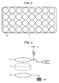
- the construction of one tactile sensor group is shown in Fig. 2 .
- one tactile sensor group t is constructed by arranging a plurality of tactile sensors CS which can independently detect contact states in an array, and the tactile sensor group t can specify a detailed contact position depending on whether any tactile sensor CS is in a contact state.
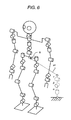
- the construction of the tactile sensor CS is schematically shown in Fig. 3 .
- the tactile sensor CS has the structure in which a space S is sandwiched between two polar plates P1 and P2, and an electric potential V cc is applied to one polar plate P1, and the other polar plate P2 is grounded.
- one polar plate P1 can be input to a microcomputer via a parallel interface (PIO), and it can be determined whether or not there is in an contact state between the polar plates, i.e., an external force is acting on the tactile sensor CS.
- PIO parallel interface
- One microcomputer is arranged in the neighborhood of every tactile sensor group t to input detection signals of all tactile sensors CS constituting a tactile sensor group and collect on/off states of these detection signals to transmit the existence/non-existence of contact with the outside in parts concerned and contact positions to a host computer.
- the pelvic part of the humanoid robot is loaded with a triaxial acceleration sensor a1 and a triaxial angular velocity sensor (gyroscope) g1.
- a microcomputer which measures values of these sensors is disposed to transmit measurement results thereof to the host computer.
- a torque sensor as shown in Fig. 4 is arranged between an output shaft of an actuator motor, and a frame, and the torque generated around a joint shaft can be measured by this torque sensor.
- the torque sensor shown has rare distorted structure, and can be constructed by a method of measuring infinitesimal deformation volume by a strain gauge. Further, torque measurement results are collected by a microcomputer equipped in an actuator, and are then transmitted to the host computer.
- connection topology in the humanoid robot shown in Fig. 1 is shown in Fig. 5 .
- the humanoid robot has triaxial waist joint actuators a1, a2, a3, and triaxial neck joint actuators a16, a17, and a18 in a body part, and these actuators are serially connected to the host computer. Further, the torque sensors tq16, tq17, and tq18 shown in Fig. 4 are arranged between an output shaft of each of the actuator motors a16, a17, and a18, and the frame. Each joint actuator receives a positional control target value through a serial cable, and transmits current output torque, joint angle, and joint angular velocity to the host computer.
- the humanoid robot has triaxial shoulder joint actuators a4, a5, and a6, a uniaxial elbow joint actuator a7, and biaxial wrist joint actuators a8 and a9 in a left arm part, torque sensors tq4, tq5, tq6, tq7, tq8, and tq9 shown in Fig. 4 are arranged between an output shaft of each of the actuator motors a4, a5, a6, a7, a8, and a9, and the frame, and these torque sensors are serially connected to the host computer.
- the humanoid robot has triaxial shoulder joint actuators a10, a11, and a12, a uniaxial elbow joint actuator a13, and biaxial wrist joint actuators a14 and a15 in a right arm part, torque sensors tq10, tq11, tq12, tq13, tq14, and tq15 shown in Fig. 4 are arranged between an output shaft of each of the actuator motors a10, a11, a12, a13, a14, and a15, and the frame, and these torque sensors are serially connected to the host computer.
- the humanoid robot has triaxial hip joint actuators a19, a20, and a21, a uniaxial knee joint actuator a22, and biaxial ankle joint actuators a23 and a24 in a left leg part, torque sensors tq19, tq20, tq21, tq22, tq23, and tq24 shown in Fig. 4 are arranged between an output shaft of each of the actuator motors a19, a20, a21, a22, a23, and a24, and the frame, and these torque sensors are serially connected to the host computer.
- the humanoid robot has triaxial hip joint actuators a25, a26, and a27, a uniaxial knee joint actuator a28, and biaxial ankle joint actuators a29 and a30 in a right leg part, torque sensors tq25, tq26, tq27, tq28, tq29, and tq30 shown in Fig. 4 are arranged between an output shaft of each of the actuator motors a25, a26, a27, a28, a29, and a30, and the frame, and these torque sensors are serially connected to the host computer.
- the actuators a1 to a30 to be used in the respective joint shafts are composed of, for example, a DC brushless motor, a reducer, and a position sensor which detects the rotational position of an output shaft of the reducer, and are rotationally driven according to positional control target values given from the outside, and output current output torques, joint angle and joint angular velocities.
- This type of joint actuator is described in, for example, JP-A-2004-181613 already transferred to the present applicant.
- a right foot part tactile sensor group t1, a right shin tactile sensor group t2, and a right thigh tactile sensor group t3 are arranged at the right leg part of the humanoid robot, and these sensor groups are serially connected to the host computer.
- the microcomputers (as mentioned) are equipped in the tactile sensor groups t1 to t3, respectively to collect the on/off states of the tactile sensors CS in each of the tactile sensor groups, and transmit them to the host computer through a serial cable.
- a left foot part tactile sensor group t9, a left thin tactile sensor group t10, and a left thigh tactile sensor group t11 are arranged in the left leg part, and the on/off states of the tactile sensors CS in each of the tactile sensor groups are collected by an internal microcomputer, and are transmitted to the host computer through a serial cable.
- a right wrist tactile sensor group t4, a right forearm tactile sensor group t5, and a right overarm tactile sensor group t6 are arranged at the right arm part of the humanoid robot, and the on/off states of the tactile sensor CS in each of the tactile sensor groups are collected by an internal microcomputer, and are transmitted to the host computer through a serial cable.
- a left wrist tactile sensor group t12, a left forearm tactile sensor group t13, and a left overarm tactile sensor group t14 are arranged at the left arm part, and the on/off states of the tactile sensors CS in each of the tactile sensor groups are collected by an internal microcomputer, and are transmitted to the host computer through a serial cable.
- body part tactile sensor groups t7 and t15 are attached to the right and left, respectively, of the body part of the humanoid robot, and the on/off states of the tactile sensors CS in each of the tactile sensor groups are collected by an internal microcomputer, and are transmitted to the host computer through a serial cable.
- head part tactile sensor groups t8 and t16 are attached to the right and left, respectively, of the head part of the humanoid robot, and the on/off states of the tactile sensors CS in each of the tactile sensor groups are collected by an internal microcomputer, and are transmitted to the host computer through a serial cable.
- FIG. 6 A joint degree-of-freedom model of the humanoid robot shown in Fig. 1 is shown in Fig. 6 .
- a bipedal walking mobile robot can be expressed as an open link tree structure with a pelvis B as a basis.
- a generalized variable q representing the whole posture of the robot can be expressed like the following Expression (1), using a vector ⁇ in which all joint values serving as the current states of actuators can be enumerated, and a vector in which the posture ⁇ and position p 0 of a base are enumerated as the motion state of the robot.
- q ⁇ ⁇ p 0 ⁇ ⁇ T
- the operational space is a space for describing the relationship between a force acting on the robot, and acceleration to be generated.
- the operational space becomes indispensable when a contact way between the robot and an environment is used as constraint conditions when joint angles of the robot are not position-controlled, but force-controlled.
- the constraint conditions referred to here include, for example, constraint conditions on the self-interference of the robot, constraint conditions of a joint movable angle, and phenomena called "a hand fits on an object" and "right and left eyes become horizontal.”
- the Cartesian coordinate system for execution of a task is an example of the operational space.
- a task such as a finger position posture at the tip of a manipulator
- the operational space As for the basic idea of the operational space, refer to, for example, " A unified approach to motion and force control of robot manipulators" (The operational space formulation, IEEE Journal of Robotics and Automation, and RA-3 (1), pp.43-53, 1987 ).
- ⁇ a generalized force corresponding to the generalized variable q
- b the gravitational force/Coriolis force
- f an external force acting on the operational space.
- c of a third term of a right side of the above Expression (4) is equivalent to operational space bias acceleration (that is, the acceleration acting on an operational space in a case where an external force does not act), and is expressed like the following Expression (6).
- c JH - 1 ⁇ ⁇ - b ⁇ J ⁇ ⁇ q ⁇
- the operational space i.e., the relationship between acceleration and a force is given by an operational space inertia inverse matrix.
- the operational space inertia inverse matrix is an important physical quantity which allows application to a number of fields, such as force control, dynamic simulation, computer animation, posture editing, and external force estimation.
- a motion generation method of generating the motion of a humanoid link-type joint by adding constraint conditions in consideration of dynamics to calculate joint acceleration or by simultaneously solving dynamical constraint conditions formulated using an operational space inertia inverse matrix representing the relationship between a force acting a link, and acceleration caused by the force, and kinematic constraint conditions is suggested (for example, refer to JP-A-2003-231077 .
- f v is a coupling vector of f and f k
- J v is a Jacobian representing an operational space of f v in which J and J k are enumerated longitudinally.
- f v is a virtual force including even a force which does not exist actually.
- the virtual force f v is realized, cooperatively using an external force f e obtained from an environment and a torque ⁇ a of an actuator of a joint part.
- J v T ⁇ f v J e T ⁇ f e + J a T ⁇ f a
- J e and J a are Jacobians corresponding to an operational space on which f e and ⁇ a act.
- e is a value which is obtained by subtracting a right side from a left side of the above Expression (11), and which gives an error of the above Expression (11).
- y is a coupling vector of ⁇ a , f e , and ⁇ f v .
- a first term of the above Expression (12) represents a condition for minimization of an error for satisfaction of the above Expression (11)
- a second term of the above Expression (12) represents a condition for minimization of a virtual force correction amount ⁇ f v , an actual force f e , and ⁇ a .
- Q 1 and Q 2 are positive definite symmetric matrices representing the weight for minimization therebetween.
- An inequality constraint expression (13) gives upper limits, lower limits, etc. of a vertical reaction force, a friction condition and a joint generating force.
- the direction of the operational space may be set in a total of three directions including a direction (one-dimensional) of a vertical reaction force, and directions (two-dimensional) of a frictional force. That is, as shown in Fig. 7 , when the contact sensor CS is turned on, a direction (f N ) of a vertical reaction force and directions (f Fx , f Fy ) of a frictional force in a part where a contact sensor CS is arranged may be determined, and an operational space may be defined.
- the direction of a vertical reaction force is approximated well by a normal vector of a robot shape in the part where the contact sensor CS is arranged.
- the directions of a frictional force two arbitrary directions orthogonal thereto may be calculated. That is, an actual external force is set in the direction of a normal vector and the direction of a tangent vector of the robot shape in a contact part.
- part of well-known reverse motion kinematic operation may be used for calculation of a Jacobian.
- the operation of obtaining a left side from a right side of the above Expression (3) is generally known as inverse dynamic operation, and can be written like the following Expression (16).
- ⁇ INV q ⁇ q ⁇ ⁇ q ⁇ ⁇ q ⁇ ⁇ q ⁇ f
- g represents the gravitational acceleration.
- a construction method of the inverse dynamic operation which is extended in the form which can be applied to a link chain with a branch floated in the air to which an external force acts like a humanoid robot, for example, refer to "Generation of a full body motion of a humanoid robot with a dynamic filter" (Doctoral Dissertation Specialized in Information Engineering of Engineering Department of Tokyo University, December, 1999, Section 4.2.2) written by Kenichiro Nagasaka.
- e i represents that an i-th element has a unit vector of 1.
- the torque ⁇ a of an actuator of a joint part obtained by solving the above Expressions (14) and (15) needs to be realized precisely. Since the torque of an actuator is proportional to the electrical current value thereof, the operation of the torque is allowed if the electrical current value is controlled. However, since any friction or the like which is difficult to model exists in an actual motor driving system, a desired torque cannot be obtained only by sending an electrical current command in an open loop.
- a torque sensor (refer to Fig. 4 ) arranged at a joint part detects information on the torque which acts on the joint part, and feeds the information back to an electrical current command.
- a torque sensor (refer to Fig. 4 ) arranged at a joint part detects information on the torque which acts on the joint part, and feeds the information back to an electrical current command.
- generating force target values of all actuators are determined by detecting contact parts with the outside without omission, using contact sensors arranged in a distributed manner over the whole body surface of a humanoid robot, and by exactly solving a mechanical model so that a desired motion may be achieved, while external forces having the detected contact parts as points of action are properly used.
- favorable tactile force interaction in which points of action are not limited can be realized by compensating a force, which is difficult to model, within each joint which connects links by a torque sensor provided at a joint part.
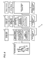
- FIG. 8 A functional block diagram of the control system 10 which realizes such a robot control method is shown in Fig. 8 .
- a mechanical model 11 holds geometric parameters and dynamical parameters of rigid body links of a robot to be controlled. Physical quantities which vary every moment according to the current state of the robot, such as joint angles, are also included in the data which the mechanical model 11 holds.
- the target value setting unit 12 sets target values relating to positions, velocity, acceleration, posture, angular velocity, angular acceleration, force, moment, etc., which are imposed on respective parts, joints, and momentum of the robot.
- the target values are set as values at a left side of the above Expression (4).
- the known force f k is stored separately.
- a virtual external force calculating unit 13 acquires a virtual external force which is required to realize the target values set in the target value setting unit 12. Specifically, as for an unknown virtual external force, a force f which satisfies the above Expressions (7) and (8) is acquired by a linear complementary problem solver 13-2. A coefficient matrix A -1 and a bias vector c of the above Expression (7) are acquired using high-speed operation of operational space physical quantities which is reported already (for example, refer to JP-A-2007-108955 ), in an operational space physical quantity calculating unit 13-1. Information on the mechanical model is utilized for calculation of the operational space physical quantities. In a case where a known virtual external force f k is further added, a virtual external force which is required as a whole is obtained by Expression (9).
- a contact part detector 14 is composed of a tactile sensor group attached to the surface of the whole body of the robot (refer to Fig. 1 ), and detects a part where the robot is in contact with the outside. As the contact part information, a rigid body link ID in contact with the outside, and contact position coordinates seen from the rigid body link are output.
- the output results of the contact part detector 14 are used for the point of action and direction of the external force obtained from an environment.
- a vertical reaction force and a frictional force which are actual external forces are set in the direction of a normal vector and the direction of a tangent vector, of a robot surface shape in a contact part detected by the contact part detector 14 (as mentioned above). Conversion processing from the virtual external force into the actual forces is achieved by solving the above Expressions (14) and (15) by a secondary programming problem solver 15-1. Among them, the actual force converting unit 15 outputs the torque ⁇ a of an actuator.
- a torque detector 16 is a torque sensor (refer to Fig. 4 ) attached to a joint part, and measures and outputs an actual torque which acts on each joint part.
- a torque feedback control unit 17 detects the variation between the torque detected by the torque detection unit 16, and a command torque, and feeds the variation back to an electrical current target value. As a result, disturbances, such as friction and inertia, which are included in a motor driving system, are suppressed, and an actuator target torque is precisely realized in each joint.
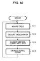
- a sequence for calculating a target torque of an actuator by the virtual external force calculating unit 13 and the actual force converting unit 15 is shown in the form of a flow chart.
- Step S1 If target values are set in the target value setting unit 12 (Step S1), joint angle, angular velocity, the posture of a pelvic part, angular velocity, etc. are detected, and the state of the mechanical model 11 is updated so as to coincide with the current motion state of the robot (Step S2).
- Step S3 operational space physical quantities are calculated (Step S3) in the virtual external force calculating unit 13, and an unknown virtual external force is further calculated by solving a linear complementary problem in the virtual external force calculating unit 13 (Step S4).
- Step S6 if a contact part is detected in the contact part detector 14 (Step S6), the virtual external force is converted into actual forces by solving a secondary programming problems in the actual force converting unit 15 (Step S7).
- an actuator-generated component is extracted, and is adopted as an actuator target torque (Step S8).
- the above processing is executed in a predetermined cycle (for example, 1 millisecond).
- a sequence for reducing any variation between an actuator force which the actual force converting unit 15 outputs, and a torque which the torque detector 16 has detected, which is executed by the torque feedback control unit 17, is shown in the form of a flow chart.
- the torque feedback control unit 17 calculates a variation between the measured torque and an actuator target torque which the actual force converting unit 15 outputs (Step S12).
- the torque feedback control unit 17 calculates an electrical current target value to an actuator motor (Step S13), and carries out electrical current control (Step S14).
- the torque feedback control unit 17 repeatedly executes the sequence shown in Fig. 10 in a faster cycle (for example, 100 microseconds) independently from the processing by the virtual external force calculating unit 13 and actual force converting unit 15 which are shown in Fig. 9 .
- FIG. 11 An aspect in which control of the humanoid robot has been made using the control system 10 which has been described hitherto is shown in Fig. 11 .
- the motion purpose is imposed so that the amount of a translational motion may be maintained at zero.
- the force control is performed.
- the robot has the passivity for redundancy and can also touch the outside flexibly.
- the robot pushes its right leg tip forward.
- the robot is maintained in a well-balanced manner without falling as a whole by cooperatively operating the whole body, such as moving a left leg reversely backward, as a result of mechanical calculation. That is, it can be understood that the robot has passivity without violating the purpose of fixation of the gravitational center.
- a case where the robot is placed on the floor surface in a crawling state, and contact points are created at the tips of both legs and both hands is shown.
- a case where the robot is placed on the floor surface in a seating position, and contact points are created at a buttock part, leg parts, and foot parts is shown.
- a case where the robot is placed on the floor surface in a bridge posture, and contact points are created at one foot and tips of both hands is shown.
- the robot is in the state of a removed force until it is placed on the floor surface, the posture shown is maintained by making full use of the floor reaction force and joint forces of the whole body so that the purpose of fixation of the gravitational center may be achieved simultaneously with ground-touching. Further, even after the robot touches the floor surface, the point that the robot has passivity with respect to redundancy is similar to the example shown in Fig. 11 .
- control system is the same, the mounting specialized in a point of action is not included at all.
- present control system it can be understood that various and flexible tactile force interaction with the outside can be achieved, using an arbitrary place of the body as a point of action.
Applications Claiming Priority (1)
| Application Number | Priority Date | Filing Date | Title |
|---|---|---|---|
| JP2007272099A JP5109573B2 (ja) | 2007-10-19 | 2007-10-19 | 制御システム及び制御方法、並びにロボット装置 |
Publications (3)
| Publication Number | Publication Date |
|---|---|
| EP2080596A2 EP2080596A2 (en) | 2009-07-22 |
| EP2080596A3 EP2080596A3 (en) | 2010-08-04 |
| EP2080596B1 true EP2080596B1 (en) | 2014-12-03 |
Family
ID=40564297
Family Applications (1)
| Application Number | Title | Priority Date | Filing Date |
|---|---|---|---|
| EP08253324.1A Active EP2080596B1 (en) | 2007-10-19 | 2008-10-13 | Control system, control method, and robot apparatus |
Country Status (3)
| Country | Link |
|---|---|
| US (1) | US8463433B2 (ja) |
| EP (1) | EP2080596B1 (ja) |
| JP (1) | JP5109573B2 (ja) |
Families Citing this family (47)
| Publication number | Priority date | Publication date | Assignee | Title |
|---|---|---|---|---|
| JP4715863B2 (ja) * | 2008-05-01 | 2011-07-06 | ソニー株式会社 | アクチュエータ制御装置及びアクチュエータ制御方法、アクチュエータ、ロボット装置、並びにコンピュータ・プログラム |
| JP4947073B2 (ja) * | 2009-03-11 | 2012-06-06 | トヨタ自動車株式会社 | ロボット装置及びその制御方法 |
| US9205887B2 (en) * | 2010-02-25 | 2015-12-08 | Honda Motor Co., Ltd. | Constrained resolved acceleration control |
| JP2011209099A (ja) | 2010-03-30 | 2011-10-20 | Sony Corp | トルクセンサおよびロボット装置 |
| US8740882B2 (en) * | 2010-07-30 | 2014-06-03 | Lg Electronics Inc. | Medical robotic system and method of controlling the same |
| KR101766755B1 (ko) * | 2010-08-17 | 2017-08-10 | 삼성전자주식회사 | 보행 로봇 및 그 제어방법 |
| US8731880B2 (en) * | 2010-09-14 | 2014-05-20 | University Of Washington Through Its Center For Commercialization | Invertible contact model |
| JP2012081568A (ja) | 2010-10-14 | 2012-04-26 | Sony Corp | ロボットの制御装置及び制御方法、並びにコンピューター・プログラム |
| US9119655B2 (en) | 2012-08-03 | 2015-09-01 | Stryker Corporation | Surgical manipulator capable of controlling a surgical instrument in multiple modes |
| US8670869B2 (en) * | 2011-05-25 | 2014-03-11 | Honda Motor Co., Ltd. | Robot controller |
| KR101953113B1 (ko) * | 2011-05-30 | 2019-03-05 | 삼성전자주식회사 | 로봇 및 그 제어방법 |
| JP5770067B2 (ja) * | 2011-11-04 | 2015-08-26 | 本田技研工業株式会社 | ロボットアーム |
| CA2879414A1 (en) | 2012-08-03 | 2014-02-06 | Stryker Corporation | Systems and methods for robotic surgery |
| US20160167222A1 (en) * | 2012-08-03 | 2016-06-16 | Nimer Mohammed Ead | Instructional humanoid robot apparatus and a method thereof |
| US9226796B2 (en) * | 2012-08-03 | 2016-01-05 | Stryker Corporation | Method for detecting a disturbance as an energy applicator of a surgical instrument traverses a cutting path |
| JP2014073222A (ja) * | 2012-10-04 | 2014-04-24 | Sony Corp | 運動補助装置及び運動補助方法 |
| JP2014205198A (ja) * | 2013-04-10 | 2014-10-30 | セイコーエプソン株式会社 | ロボット、ロボット制御装置およびロボットシステム |
| JP6354122B2 (ja) * | 2013-06-05 | 2018-07-11 | セイコーエプソン株式会社 | ロボット |
| US9120227B2 (en) * | 2013-08-15 | 2015-09-01 | Disney Enterprises, Inc. | Human motion tracking control with strict contact force constraints for floating-base humanoid robots |
| JP6272885B2 (ja) | 2013-09-24 | 2018-01-31 | ソニー・オリンパスメディカルソリューションズ株式会社 | 医療用ロボットアーム装置、医療用ロボットアーム制御システム、医療用ロボットアーム制御方法及びプログラム |
| WO2015137040A1 (ja) * | 2014-03-14 | 2015-09-17 | ソニー株式会社 | ロボットアーム装置、ロボットアーム制御方法及びプログラム |
| JP6512216B2 (ja) | 2014-03-14 | 2019-05-15 | ソニー株式会社 | ロボットアーム装置、ロボットアーム制御方法及びプログラム |
| EP3135445B1 (en) | 2014-03-28 | 2021-04-28 | Sony Corporation | Robot arm device |
| US9308648B2 (en) * | 2014-07-24 | 2016-04-12 | Google Inc. | Systems and methods for robotic self-right |
| US10518409B2 (en) * | 2014-09-02 | 2019-12-31 | Mark Oleynik | Robotic manipulation methods and systems for executing a domain-specific application in an instrumented environment with electronic minimanipulation libraries |
| JP6104867B2 (ja) * | 2014-09-19 | 2017-03-29 | Thk株式会社 | ロボット上半身の支持構造 |
| US9403275B2 (en) * | 2014-10-17 | 2016-08-02 | GM Global Technology Operations LLC | Dynamic obstacle avoidance in a robotic system |
| US9481086B2 (en) * | 2015-02-18 | 2016-11-01 | Disney Enterprises, Inc. | Control method for floating-base robots including generating feasible motions using time warping |
| WO2016152046A1 (en) | 2015-03-23 | 2016-09-29 | Sony Corporation | Medical support arm device and method of controlling medical support arm device |
| DE102015108010B3 (de) * | 2015-05-20 | 2016-06-02 | Cavos Bagatelle Verwaltungs Gmbh & Co. Kg | Steuern und Regeln von Aktoren eines Roboters unter Berücksichtigung von Umgebungskontakten |
| WO2017033352A1 (ja) * | 2015-08-25 | 2017-03-02 | 川崎重工業株式会社 | 産業用遠隔操作ロボットシステム |
| JP6660242B2 (ja) * | 2016-04-25 | 2020-03-11 | 本田技研工業株式会社 | ロボットの制御信号を伝送するための光ファイバ配線構造 |
| JP2018075121A (ja) | 2016-11-08 | 2018-05-17 | ソニー株式会社 | 医療用支持アーム装置 |
| WO2018112025A1 (en) | 2016-12-16 | 2018-06-21 | Mako Surgical Corp. | Techniques for modifying tool operation in a surgical robotic system based on comparing actual and commanded states of the tool relative to a surgical site |
| US11478133B2 (en) | 2017-02-28 | 2022-10-25 | Sony Corporation | Medical observation system, apparatus for controlling the same, and method for controlling the same |
| JP6927727B2 (ja) * | 2017-03-29 | 2021-09-01 | 本田技研工業株式会社 | ロボットの制御装置 |
| WO2018198480A1 (ja) * | 2017-04-28 | 2018-11-01 | ソニー株式会社 | 制御装置、および制御方法 |
| CN107351090A (zh) * | 2017-09-05 | 2017-11-17 | 南京阿凡达机器人科技有限公司 | 一种机器人控制系统及方法 |
| US10807246B2 (en) * | 2018-01-08 | 2020-10-20 | Beijing Jingdong Shangke Information Technology Co., Ltd. | Mobile robotic device and method of controlling the same manipulator for locomotion and manipulation |
| TWI704471B (zh) * | 2018-09-27 | 2020-09-11 | 仁寶電腦工業股份有限公司 | 互動式電子裝置及其互動方法 |
| JP7192359B2 (ja) * | 2018-09-28 | 2022-12-20 | セイコーエプソン株式会社 | ロボットを制御する制御装置、および制御方法 |
| EP3886751A1 (en) | 2019-01-23 | 2021-10-06 | Sony Group Corporation | Medical arm system, control device, control method, and program |
| US11292126B2 (en) * | 2019-10-17 | 2022-04-05 | Disney Enterprises, Inc. | Robots with robust bipedal locomotion supported with non-conventional physics |
| DE102019134665B3 (de) * | 2019-12-17 | 2020-12-10 | Franka Emika Gmbh | Kalibrieren eines virtuellen Kraftsensors eines Robotermanipulators |
| DE102019134666B4 (de) * | 2019-12-17 | 2022-03-31 | Franka Emika Gmbh | Kalibrieren eines virtuellen Kraftsensors eines Robotermanipulators |
| US11548150B2 (en) | 2020-05-29 | 2023-01-10 | Mitsubishi Electric Research Laboratories, Inc. | Apparatus and method for planning contact-interaction trajectories |
| CN114179088B (zh) * | 2021-12-27 | 2024-01-19 | 优必康(青岛)科技有限公司 | 机器人负载补偿实现方法、装置及机器人 |
Family Cites Families (18)
| Publication number | Priority date | Publication date | Assignee | Title |
|---|---|---|---|---|
| JPS59108691A (ja) * | 1982-12-13 | 1984-06-23 | 株式会社日立製作所 | バランサ制御方式 |
| JP3167420B2 (ja) * | 1992-04-30 | 2001-05-21 | 本田技研工業株式会社 | 脚式移動ロボットの歩行制御装置 |
| JP3672426B2 (ja) * | 1996-12-19 | 2005-07-20 | 本田技研工業株式会社 | 脚式移動ロボットの姿勢制御装置 |
| EP0965416B1 (en) | 1996-12-19 | 2005-12-07 | Honda Giken Kogyo Kabushiki Kaisha | Attitude controller of legged moving robot |
| JP3615702B2 (ja) | 1999-11-25 | 2005-02-02 | ソニー株式会社 | 脚式移動ロボットの動作制御装置及び動作制御方法、並びに、脚式移動ロボット |
| JP3511088B2 (ja) * | 2000-04-10 | 2004-03-29 | 独立行政法人航空宇宙技術研究所 | 多関節介護ロボット制御用の圧力分布センサ |
| JP3760186B2 (ja) | 2001-06-07 | 2006-03-29 | 独立行政法人科学技術振興機構 | 二脚歩行式移動装置及びその歩行制御装置並びに歩行制御方法 |
| JP3951007B2 (ja) * | 2001-09-14 | 2007-08-01 | 独立行政法人産業技術総合研究所 | 触覚センサを持つロボット用制御装置 |
| JP3790816B2 (ja) * | 2002-02-12 | 2006-06-28 | 国立大学法人 東京大学 | 人型リンク系の運動生成方法 |
| JP3522742B1 (ja) * | 2002-03-18 | 2004-04-26 | ソニー株式会社 | ロボット装置、脚式移動ロボットの動作制御装置及び動作制御方法、脚式移動ロボットのためのセンサ・システム、並びに移動体装置 |
| JP2004015925A (ja) * | 2002-06-07 | 2004-01-15 | Mitsuba Corp | ブラシレスモータ制御方法 |
| US7805218B2 (en) * | 2002-10-01 | 2010-09-28 | Sony Corporation | Robot device and control method of robot device |
| EP1607191A1 (en) * | 2003-03-23 | 2005-12-21 | Sony Corporation | Robot device and method of controlling the same |
| WO2005005108A1 (ja) | 2003-07-11 | 2005-01-20 | Honda Motor Co., Ltd. | 2足歩行移動体の関節モーメント推定方法 |
| JP4440759B2 (ja) * | 2004-12-17 | 2010-03-24 | 本田技研工業株式会社 | 2足歩行移動体の床反力推定方法 |
| US7313463B2 (en) * | 2005-03-31 | 2007-12-25 | Massachusetts Institute Of Technology | Biomimetic motion and balance controllers for use in prosthetics, orthotics and robotics |
| JP4595727B2 (ja) * | 2005-07-22 | 2010-12-08 | ソニー株式会社 | 外力推定システム及び外力推定方法、並びにコンピュータ・プログラム |
| JP4682791B2 (ja) | 2005-10-12 | 2011-05-11 | ソニー株式会社 | 操作空間物理量算出装置及び操作空間物理量算出方法、並びにコンピュータ・プログラム |
-
2007
- 2007-10-19 JP JP2007272099A patent/JP5109573B2/ja active Active
-
2008
- 2008-10-09 US US12/248,121 patent/US8463433B2/en active Active
- 2008-10-13 EP EP08253324.1A patent/EP2080596B1/en active Active
Also Published As
| Publication number | Publication date |
|---|---|
| EP2080596A2 (en) | 2009-07-22 |
| US20090105878A1 (en) | 2009-04-23 |
| JP2009095959A (ja) | 2009-05-07 |
| JP5109573B2 (ja) | 2012-12-26 |
| US8463433B2 (en) | 2013-06-11 |
| EP2080596A3 (en) | 2010-08-04 |
Similar Documents
| Publication | Publication Date | Title |
|---|---|---|
| EP2080596B1 (en) | Control system, control method, and robot apparatus | |
| JP4595727B2 (ja) | 外力推定システム及び外力推定方法、並びにコンピュータ・プログラム | |
| US11305431B2 (en) | System and method for instructing a robot | |
| Xu et al. | Kinematics, dynamics, and control of a cable-driven hyper-redundant manipulator | |
| US8340822B2 (en) | Actuator control device, actuator control method, actuator, robot apparatus, and computer program | |
| EP2895305B1 (en) | Constraining robotic manipulators with redundant degrees of freedom | |
| Khalil et al. | SYMORO+: a system for the symbolic modelling of robots | |
| Ghan et al. | System identification for the Berkeley lower extremity exoskeleton (BLEEX) | |
| US20120130541A1 (en) | Method and apparatus for robot teaching | |
| Nenchev | Reaction null space of a multibody system with applications in robotics | |
| EP3117967A1 (en) | Transparency control method for robotic devices and a control device therefor | |
| Li et al. | Visual servoing of flexible-link manipulators by considering vibration suppression without deformation measurements | |
| Kaplish et al. | Motion retargeting and control for teleoperated physical human-robot interaction | |
| Fresonke et al. | Deflection prediction for serial manipulators | |
| Rehnmark et al. | Robonaut: The'short list'of technology hurdles | |
| Williams et al. | A 4-degree-of-freedom parallel origami haptic device for normal, shear, and torsion feedback | |
| Bergamasco et al. | Exoskeletons as man-machine interface systems for teleoperation and interaction in virtual environments | |
| Tiseo et al. | Hapfic: An adaptive force/position controller for safe environment interaction in articulated systems | |
| Choi et al. | Development of the Cartesian arm exoskeleton system (CAES) using a 3-axis force/torque sensor | |
| Prasanga et al. | Simultaneous bipedal locomotion based on haptics for teleoperation | |
| Velásquez-Lobo et al. | Modeling a biped robot on matlab/simmechanics | |
| Hunt et al. | Optimizing stiffness of a novel parallel-actuated robotic shoulder exoskeleton for a desired task or workspace | |
| Pfeiffer | Path and force control of elastic manipulators | |
| Rodríguez-Angeles et al. | User wearable interface based on inertial sensors for unilateral master-slave robot teleoperation | |
| Ayala et al. | GarRobot: Design, Construction and Control of a Teleoperated Climbing Robot Inspired by Geckos |
Legal Events
| Date | Code | Title | Description |
|---|---|---|---|
| PUAI | Public reference made under article 153(3) epc to a published international application that has entered the european phase |
Free format text: ORIGINAL CODE: 0009012 |
|
| 17P | Request for examination filed |
Effective date: 20081030 |
|
| AK | Designated contracting states |
Kind code of ref document: A2 Designated state(s): AT BE BG CH CY CZ DE DK EE ES FI FR GB GR HR HU IE IS IT LI LT LU LV MC MT NL NO PL PT RO SE SI SK TR |
|
| AX | Request for extension of the european patent |
Extension state: AL BA MK RS |
|
| PUAL | Search report despatched |
Free format text: ORIGINAL CODE: 0009013 |
|
| AK | Designated contracting states |
Kind code of ref document: A3 Designated state(s): AT BE BG CH CY CZ DE DK EE ES FI FR GB GR HR HU IE IS IT LI LT LU LV MC MT NL NO PL PT RO SE SI SK TR |
|
| AX | Request for extension of the european patent |
Extension state: AL BA MK RS |
|
| AKX | Designation fees paid |
Designated state(s): DE FR GB |
|
| 17Q | First examination report despatched |
Effective date: 20110909 |
|
| GRAP | Despatch of communication of intention to grant a patent |
Free format text: ORIGINAL CODE: EPIDOSNIGR1 |
|
| INTG | Intention to grant announced |
Effective date: 20140109 |
|
| GRAS | Grant fee paid |
Free format text: ORIGINAL CODE: EPIDOSNIGR3 |
|
| GRAA | (expected) grant |
Free format text: ORIGINAL CODE: 0009210 |
|
| AK | Designated contracting states |
Kind code of ref document: B1 Designated state(s): DE FR GB |
|
| REG | Reference to a national code |
Ref country code: GB Ref legal event code: FG4D |
|
| REG | Reference to a national code |
Ref country code: DE Ref legal event code: R096 Ref document number: 602008035660 Country of ref document: DE Effective date: 20150108 |
|
| REG | Reference to a national code |
Ref country code: DE Ref legal event code: R084 Ref document number: 602008035660 Country of ref document: DE |
|
| REG | Reference to a national code |
Ref country code: GB Ref legal event code: 746 Effective date: 20150421 |
|
| REG | Reference to a national code |
Ref country code: DE Ref legal event code: R084 Ref document number: 602008035660 Country of ref document: DE Effective date: 20150410 |
|
| REG | Reference to a national code |
Ref country code: DE Ref legal event code: R097 Ref document number: 602008035660 Country of ref document: DE |
|
| PLBE | No opposition filed within time limit |
Free format text: ORIGINAL CODE: 0009261 |
|
| STAA | Information on the status of an ep patent application or granted ep patent |
Free format text: STATUS: NO OPPOSITION FILED WITHIN TIME LIMIT |
|
| REG | Reference to a national code |
Ref country code: FR Ref legal event code: PLFP Year of fee payment: 8 |
|
| 26N | No opposition filed |
Effective date: 20150904 |
|
| REG | Reference to a national code |
Ref country code: FR Ref legal event code: PLFP Year of fee payment: 9 |
|
| REG | Reference to a national code |
Ref country code: FR Ref legal event code: PLFP Year of fee payment: 10 |
|
| REG | Reference to a national code |
Ref country code: FR Ref legal event code: PLFP Year of fee payment: 11 |
|
| PGFP | Annual fee paid to national office [announced via postgrant information from national office to epo] |
Ref country code: GB Payment date: 20220922 Year of fee payment: 15 |
|
| PGFP | Annual fee paid to national office [announced via postgrant information from national office to epo] |
Ref country code: FR Payment date: 20220922 Year of fee payment: 15 |
|
| PGFP | Annual fee paid to national office [announced via postgrant information from national office to epo] |
Ref country code: DE Payment date: 20220616 Year of fee payment: 15 |
|
| P01 | Opt-out of the competence of the unified patent court (upc) registered |
Effective date: 20230527 |