EP2079561B1 - Fasteners and spacer rings therefor - Google Patents
Fasteners and spacer rings therefor Download PDFInfo
- Publication number
- EP2079561B1 EP2079561B1 EP07815355.8A EP07815355A EP2079561B1 EP 2079561 B1 EP2079561 B1 EP 2079561B1 EP 07815355 A EP07815355 A EP 07815355A EP 2079561 B1 EP2079561 B1 EP 2079561B1
- Authority
- EP
- European Patent Office
- Prior art keywords
- spacer
- spacer ring
- expanding
- nut
- faces
- Prior art date
- Legal status (The legal status is an assumption and is not a legal conclusion. Google has not performed a legal analysis and makes no representation as to the accuracy of the status listed.)
- Active
Links
Images


Classifications
-
- B—PERFORMING OPERATIONS; TRANSPORTING
- B25—HAND TOOLS; PORTABLE POWER-DRIVEN TOOLS; MANIPULATORS
- B25B—TOOLS OR BENCH DEVICES NOT OTHERWISE PROVIDED FOR, FOR FASTENING, CONNECTING, DISENGAGING, OR HOLDING
- B25B29/00—Accessories
- B25B29/02—Bolt tensioners
-
- F—MECHANICAL ENGINEERING; LIGHTING; HEATING; WEAPONS; BLASTING
- F16—ENGINEERING ELEMENTS AND UNITS; GENERAL MEASURES FOR PRODUCING AND MAINTAINING EFFECTIVE FUNCTIONING OF MACHINES OR INSTALLATIONS; THERMAL INSULATION IN GENERAL
- F16B—DEVICES FOR FASTENING OR SECURING CONSTRUCTIONAL ELEMENTS OR MACHINE PARTS TOGETHER, e.g. NAILS, BOLTS, CIRCLIPS, CLAMPS, CLIPS OR WEDGES; JOINTS OR JOINTING
- F16B31/00—Screwed connections specially modified in view of tensile load; Break-bolts
- F16B31/04—Screwed connections specially modified in view of tensile load; Break-bolts for maintaining a tensile load
-
- F—MECHANICAL ENGINEERING; LIGHTING; HEATING; WEAPONS; BLASTING
- F16—ENGINEERING ELEMENTS AND UNITS; GENERAL MEASURES FOR PRODUCING AND MAINTAINING EFFECTIVE FUNCTIONING OF MACHINES OR INSTALLATIONS; THERMAL INSULATION IN GENERAL
- F16B—DEVICES FOR FASTENING OR SECURING CONSTRUCTIONAL ELEMENTS OR MACHINE PARTS TOGETHER, e.g. NAILS, BOLTS, CIRCLIPS, CLAMPS, CLIPS OR WEDGES; JOINTS OR JOINTING
- F16B43/00—Washers or equivalent devices; Other devices for supporting bolt-heads or nuts
- F16B43/009—Washers or equivalent devices; Other devices for supporting bolt-heads or nuts with a wedging effect in order to adjust the height of the washer
Definitions
- THIS INVENTION relates to fasteners and spacer rings therefor.
- the invention particularly relates, but is not limited to, fasteners used in tensioning systems which employ hydraulic tensioning jacks.
- WO 94/01689 A1 discloses a locking fastener with coacting ramp surfaces that are provided on a nut and a washer.
- a spring member formed from an elastic material can be used between the nut and the washer.
- a screw locking assembly with a pair of washers having inclined surfaces is disclosed in US 6966735 B1 .
- An upper washer can be integrated with a nut member.
- an expanding spacer to be mounted about a bolt being tensioned, incorporating a nut engageable with the bolt, and a rotatable spacer ring with a planar end face engageable with a component to be clamped, the nut and the rotatable spacer ring having complementary helically ramped faces terminated by abutment faces, wherein at least one compression spring is mounted in, and extends from, the abutment faces to urge the expanding spacer to the expanded position and wherein the angle of inclination of each of the ramped faces to the planar end face of the rotatable spacer ring is selected so there will be no relative rotation or motion between the nut and the rotatable spacer ring while the expanding spacer is subject to an applied compressive load; wherein:
- An expanding spacer can be mounted, about a bolt being tensioned, between a nut engaged with the bolt and with a component to be clamped, the expanding spacer having complementary first and second spacer rings, each of the spacer rings having a planar end face and helically ramped faces terminated by abutment faces, where the angle of inclination of the helically ramped faces to the planar end faces is selected so that there will be no relative rotational motion between the first and second spacer rings when the expanding spacer is interposed between the nut and the component, and a compressive load is applied to the expanding spacer.
- the present invention resides in an expanding spacer, to be mounted about a bolt being tensioned, incorporating a nut engageable with the bolt, and a spacer ring with a planar end face engageable with a component to be clamped, the nut and the spacer ring having complementary helically ramped faces terminated by abutment faces, where the angle of inclination of the ramped faces to the planar end face of the spacer ring selected so there will be no relative rotation or motion between the nut and the spacer ring when the expanding spacer is subject to a compressive load.
- An intermediate spacer ring is interposed between the nut and the spacer ring, the intermediate spacer ring having oppositely-directed helically ramped faces terminated by abutment faces, where the inclination of the respective helically ramped faces is selected so that there will be no relative rotational motion between the intermediate spacer ring and the first and second spacer rings, or between the intermediate spacer ring and the nut and the spacer ring, when the expanding spacer is subject to a compressive load.
- An annular collar may be provided within the expanding spacer to maintain the first and second spacer rings, or the nut and spacer ring (and/or the intermediate spacer ring) in axial alignment, as the compressive load is applied to the expanding spacer.
- the abutment faces lie on an axis perpendicular to the plane of the planar end faces (eg., parallel to the axis of the bolt); and recesses may be formed in the abutment faces to enable the insertion of a tool to selectively rotate the first and second spacer rings, or the spacer ring, and/or the intermediate spacer ring, between an expanded position when the bolt is being tensioned, and a "collapsed" position when the nut is to be rotated on the bolt to release the tension.
- Each spacer ring may be provided with two or more, but usually no more than three or four, helically ramped faces.
- a typical angle of inclination of the helically ramped faces to the planar end face(s) is 13°, and preferably less than 25°.
- the actual angle of inclination will depend on the particular application for the expanding spacer.
- the angle of inclination for the helically ramped faces may be halved (eg., 6.5°), although the intermediate spacer enables a quicker take-up of the strain gap for a given relative rotation of the spacer ring(s).
- a peripheral flange may be provided around the second spacer ring, or spacer ring, to bear on the component and to be engaged by the bridge of a hydraulic jack operable to tension the bolt.
- the expanding spacer can be mounted about a bolt being tensioned, incorporating a nut engageable with the bolt, and a spacer ring with a planar face engageable with a component to be clamped; the nut and spacer ring having complementary respective external and internal screw threads to enable expansion and contraction of the expanding spacer by relative rotation of the spacer ring to the nut.
- the nut has secondary, preferably tapered, screw threads for engagement with a puller bar of a tensioning device.
- the expanding spacer 10 is designed to be mounted about a bolt, and interposed between a nut and a component to be clamped (all not shown) where the bolt is to be tensioned using an hydraulic tensioning jack as disclosed in International Publication WO 00/51791 (Bucknell) as hereinbefore referred to.
- an hydraulic tensioning jack as disclosed in International Publication WO 00/51791 (Bucknell) as hereinbefore referred to.
- the operation of the hydraulic tensioning system disclosed in that International Publication, and of the tensioning system disclosed in International Publication WO 2005/123345 (Bucknell) is to be incorporated into this specification by reference.
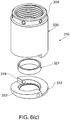
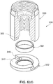
- the expanding spacer 10 has complementary first and second spacer rings 11, 12, where the second spacer ring 12 has a peripheral flange 13 engageable by the bridge of the hydraulic tensioning jack.
- the first and second spacer rings 11, 12 have planar end faces 14, 15 engageable by the nut and the component to be clamped.
- the spacer rings 11, 12 have three helically ramped faces 16, 17 which are terminated by abutment faces 18, 19, respectively.
- the helically ramped faces 16, 17 are inclined at an angle of inclination of approximately 13° to the planar end faces 14, 15.
- Compression coil springs 20 are mounted in, and extend from, the abutment faces 19 of the second spacer ring 12 to engage the opposed abutment faces 18 of the first spacer ring 11 to urge the expanding spacer 10 to rotate to an "expanded" position where the expanding spacer 10 fills a strain gap between the nut and the component to be clamped as the bolt is tensioned by the hydraulic jack.
- An annular collar is received in the bores 22, 23 in the spacer rings 11, 12 to maintain the spacer rings 11, 12 in co-axial alignment as they rotate relative to each other.
- Holes 24 are provided in the first spacer ring 11 for engagement by a tool to enable relative rotation of the first and second spacer rings 11, 12, eg., to move the expanding spacer to its "collapsed" position when the nut is to be rotated on the bolt to enable the tension on the bolt to be reduced.
- recesses 25, 26 are formed in the abutment faces 18, 19 (or at the junction of abutment faces 18, 19 with the adjacent helically ramped faces 16, 17) to enable engagement by a tool to enable the spacer rings 11, 12 to be rotated relative to each other to expand or contract the expanding spacer 10.
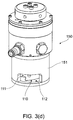
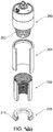
- the expanding spacer 110 has first and second spacer rings 111, 112 of the same configuration as the spacer rings 11, 12 of expanding spacer 10.
- the nut 130 which has a screw threaded bore 131 to engage the bolt (not shown) and a "quick start" tapered bore 132 to receive a complementary puller bar on a hydraulic jack (not shown), has an annular extension 133 which is received within the spacer rings 111, 112 to maintain them in co-axial alignment in the manner of the annular collar 21 of the expanding spacer 10.
- the expanding spacer 110 is provided between the bolt 130 and the component to be clamped (not shown) where the hydraulic jack 150, which has a puller bar (not shown) operable to engage the tapered thread 132 in the nut 130 and has a bridge 151 which engages the peripheral flange 113 on the second spacer ring 112.
- the hydraulic jack 150 which has a puller bar (not shown) operable to engage the tapered thread 132 in the nut 130 and has a bridge 151 which engages the peripheral flange 113 on the second spacer ring 112.
- the first spacer ring 111 is rotated relative to the second spacer ring 112, eg., by the engagement of a tool in hole(s) 124, or by the compression coil springs (not shown), to move the expanding spacer 110 to its expanded position, ie., from the position shown in FIGS. 3(c) and (d) where the abutment faces 118, 119 are engaged, to the expanded position shown in FIGS. 3(e) and (f) where the abutment faces 118, 119 are spaced apart.
- the expanding spacer 110 enables the strain gap between the planar end face 134 of the nut 130 and the component to be quickly taken up.
- the nut 230 has a planar end face 234 and does not extend into the bores of the spacer rings 211, 212 of the expanding spacer 210.
- the spacer rings 211, 212 are maintained co-axially by the bolt about which the expanding spacer 210 is mounted.
- the hydraulic ram 250 has a detachable bridge 251 which is placed around the nut 230, the bridge spanning the peripheral flange 213 on the second spacer ring 212 of the expanding spacer 210 and an annular end face 252 on the body of the hydraulic jack 250.
- one end of the nut 330 is provided with the helically ramped faces 316 and abutment faces 318 corresponding to the first spacer ring 11 of the expanding spacer 10; while a spacer ring 312 has complementary helically ramped faces 317 and abutment faces 319.
- An annular collar is received in bores 322, 323 to maintain the nut 330 and the spacer ring 312 in co-axial alignment.
- the spacer ring 312 does not incorporate a peripheral flange; and holes 324 are provided around the top of the nut 330 to enable rotation of the nut 330 relative to the spacer ring 312 to move the expanding spacer 310 between its expanded and collapsed positions.
- FIGS. 7(a) to (d) illustrate an expanding spacer where the nut 430 has an externally tapered thread 432 to engage a complementary thread on a puller bar 455 of the hydraulic jack 450 and where the bridge 451 of the hydraulic jack 450 bears directly on the component to be clamped (not shown).
- the annular collar 421 maintains the nut 430 and the spacer ring 412 of the expanding spacer 410 in correct co-axial alignment.
- the expanding spacer 10 has an intermediate spacer ring 690 may be provided between the first and second spacer rings 611, 612 where the intermediate spacer ring 690 has opposed helically ramped faces and abutment faces 693, 694 complementary to the helically ramped faces 616, 617 and abutment faces 618, 619 of the first and second spacer rings 611, 612.
- the "top" side of the intermediate spacer ring 690 would have helically ramped faces 691 and abutment faces 693 arranged to co-operate with the helically ramped faces 616 and abutment faces 618 of the first spacer ring 611; and the "bottom” side of the intermediate spacer ring 690 would have helically ramped faces 692 and abutment faces 694 complementary to the helically ramped faces 617 and abutment faces 619 of the second spacer ring 612.
- One advantage of the intermediate spacer ring 690 is that for each 1° of rotation of the intermediate spacer ring 690 (in the direction of arrow A) relative to the first and second spacer rings 611, 612 the expanding spacer 610 actually expands at a rate double (in the direction of Arrow B) for the same 1° of relative rotation between the first and second spacer rings 11, 12 of spacer 10.
- the intermediate spacer ring 690 may be rotated relative to the spacer rings 611, 612 by inserting a tool in spaced holes 699.
- the actual angle of inclination of the helically ramped faces relative to the planar end faces of the end spacers can be varied, but will normally be relatively shallow, ie., less than 25°, so that when the compressive load is applied to the expanding spacers, ie., when the hydraulic jacks release their tension on the nuts, the friction generated between the opposed helically ramped faces of the first and second spacer rings, or of the nut and of the spacer ring, and/or the intermediate spacer ring, will prevent relative rotational motion between the adjacent components. In this way, the strain gap between the nut and the component to be clamped will be maintained.
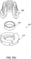
- FIGS. 9(a) to (e) illustrate an expanding spacer 710, having a nut 730 and spacer ring 712.
- the nut 730 has a body 732 central bore with internal screw threads 733 engageable with the bolt to be tensioned, not shown.
- the upper end of the body 732 has external screw threads 731 engageable with a puller bar (not shown) of a hydraulic jack (of the type illustrated with respect to other embodiments); while the lower end of the body 732 has external screw threads 736 complementary with internal screw threads 713 in the body 714 of the spacer ring 712.
- the body 714 has a planar annular bottom face 715 and an abutment face 716 formed by an inwardly directed circumferential flange 717.
- the annular bottom face 715 and an annular top face 718 on the body 714 are engageable by complementary annular faces 737, 738 on the body 732 of the nut 730.
- the spacer ring 712 can be rotated relative to the nut 730 using a tool engaged in the spaced holes 724 in the spacer ring 712.
- the expanding spacer 710 is engaged with the bolt to be tensioned, and the nut 730 is connected thereto by the internal threads 733.
- the spacer 710 is in the configuration shown in FIG 7(d) .
- a puller bar, with a tapered female thread, of a hydraulic jack is engaged with the external threads 731 on the nut 730.
- the puller bar is then released.
Landscapes
- Engineering & Computer Science (AREA)
- General Engineering & Computer Science (AREA)
- Mechanical Engineering (AREA)
- Hand Tools For Fitting Together And Separating, Or Other Hand Tools (AREA)
- Bridges Or Land Bridges (AREA)
- Bolts, Nuts, And Washers (AREA)
- Clamps And Clips (AREA)
Applications Claiming Priority (2)
| Application Number | Priority Date | Filing Date | Title |
|---|---|---|---|
| AU2006906043A AU2006906043A0 (en) | 2006-10-31 | Fasteners and spacer rings therefor | |
| PCT/AU2007/001550 WO2008052245A1 (en) | 2006-10-31 | 2007-10-11 | Fasteners and spacer rings therefor |
Publications (3)
| Publication Number | Publication Date |
|---|---|
| EP2079561A1 EP2079561A1 (en) | 2009-07-22 |
| EP2079561A4 EP2079561A4 (en) | 2016-05-18 |
| EP2079561B1 true EP2079561B1 (en) | 2019-03-27 |
Family
ID=39343674
Family Applications (1)
| Application Number | Title | Priority Date | Filing Date |
|---|---|---|---|
| EP07815355.8A Active EP2079561B1 (en) | 2006-10-31 | 2007-10-11 | Fasteners and spacer rings therefor |
Country Status (7)
| Country | Link |
|---|---|
| US (1) | US8328491B2 (enExample) |
| EP (1) | EP2079561B1 (enExample) |
| JP (1) | JP5247713B2 (enExample) |
| CN (1) | CN101583466B (enExample) |
| AU (1) | AU2007314129B2 (enExample) |
| CA (1) | CA2669306C (enExample) |
| WO (1) | WO2008052245A1 (enExample) |
Families Citing this family (17)
| Publication number | Priority date | Publication date | Assignee | Title |
|---|---|---|---|---|
| AT414346B (de) * | 2003-09-05 | 2013-10-15 | Best On Bolt Gmbh | Sicherungselement zur sicherung von schraubenelementen |
| DE102009042453A1 (de) * | 2009-09-23 | 2011-03-31 | Erwin Weh | Hochdruckverschraubung mit Planabdichtung |
| CN201636143U (zh) * | 2010-03-31 | 2010-11-17 | 中山大洋电机制造有限公司 | 一种锁紧装置 |
| GB2484064B (en) | 2010-08-26 | 2016-01-06 | Rotite Ltd | Connector and method of connecting two items together |
| US8579572B1 (en) * | 2012-07-23 | 2013-11-12 | Michael James Psimas | Load-relief washer assembly for threaded fasteners |
| US10117679B2 (en) * | 2015-03-02 | 2018-11-06 | Globus Medical, Inc. | Adjustable height pedicle screw |
| EP3267784B1 (en) * | 2015-03-13 | 2019-04-17 | Husqvarna AB | Arrangement for automatic adjustment of a spacing between cutting blades |
| JP6585682B2 (ja) * | 2017-10-26 | 2019-10-02 | 本田技研工業株式会社 | 回転体ユニットおよびベアリング予圧付与方法 |
| KR102701618B1 (ko) * | 2018-12-27 | 2024-09-03 | 삼성전자주식회사 | 스터드 |
| CA3179387A1 (en) * | 2020-04-17 | 2021-10-21 | Mitek Holdings, Inc. | Expandable washer |
| WO2021224979A1 (ja) * | 2020-05-08 | 2021-11-11 | ボルトエンジニア株式会社 | ワッシャ |
| GB2613866B (en) * | 2021-12-17 | 2024-10-02 | Ocado Innovation Ltd | An Adjustable spacer |
| US12117037B1 (en) * | 2023-09-02 | 2024-10-15 | Zoltan A. Kemeny | Fastener assemblies, cam locking fastener components, and cam interfaces |
| WO2025116749A1 (en) * | 2023-11-30 | 2025-06-05 | Resolute Solutions Limited | A shim with an adjusting mechanism, and a method of using same |
| US20250179759A1 (en) * | 2023-12-04 | 2025-06-05 | Timothy Swilley | Expandable Shim Systems and Methods |
| CN120613600A (zh) * | 2024-03-08 | 2025-09-09 | 东莞莫仕连接器有限公司 | 浮动连接器紧固件 |
| US20250313085A1 (en) * | 2024-04-05 | 2025-10-09 | Muncie Power Products, Inc. | Adjustable shim |
Family Cites Families (20)
| Publication number | Priority date | Publication date | Assignee | Title |
|---|---|---|---|---|
| US625529A (en) | 1899-05-23 | Nut-lock | ||
| US1746978A (en) | 1928-11-17 | 1930-02-11 | Carl J Winkler | Adapter for bearings |
| GB812789A (en) * | 1957-03-04 | 1959-04-29 | Gerd Lurssen | Improvements in or relating to adjustable packing-pieces for supporting machinery and the like |
| US3285568A (en) * | 1965-03-17 | 1966-11-15 | Biach Ind | Tensioning apparatus |
| SE445848B (sv) | 1983-06-10 | 1986-07-21 | Nobex Ab | Tvadelad lasbricka med kilverkan |
| US4708555A (en) * | 1985-12-19 | 1987-11-24 | Terry Sydney L | Locking fastener |
| US5190423A (en) * | 1991-02-15 | 1993-03-02 | Ewing Paul E | Locking fastener |
| US5253967A (en) * | 1991-11-08 | 1993-10-19 | Biach Industries | Adapter assembly for tensioning threaded fasteners and method of tensioning threaded fasteners |
| GB2265429A (en) * | 1992-03-18 | 1993-09-29 | Yang Tai Her | "i mprovements in screws or nuts" |
| AU4676193A (en) * | 1992-07-13 | 1994-01-31 | Sydney L. Terry | Fastener assembly |
| JP2613537B2 (ja) * | 1993-04-12 | 1997-05-28 | 寛 柿本 | ロックナット |
| DE19642446C2 (de) * | 1996-10-15 | 2000-06-15 | Ewald Witte Gmbh & Co Kg | Vorrichtung zum Halten zweier Bauteile in einer Abstandslage zueinander |
| JP4331821B2 (ja) * | 1998-05-04 | 2009-09-16 | シュヴァルツビッヒ イェルク | 構造部品を相互連結するための装置および方法 |
| DE19905706C2 (de) * | 1999-02-11 | 2003-02-27 | Nedschroef Plettenberg Gmbh | Kombimutter mit schräger Unterlegscheibe |
| AUPP890599A0 (en) | 1999-02-26 | 1999-03-25 | Bucknell, John Wentworth | Tensioning hydraulic nuts |
| WO2000077410A1 (fr) * | 1999-06-14 | 2000-12-21 | Masaki Yamazaki | Dispositif de visserie |
| JP4573931B2 (ja) * | 1999-09-08 | 2010-11-04 | 泰和 楊 | 締結具 |
| US7168902B2 (en) * | 2002-10-09 | 2007-01-30 | Terry Sydney L | Wedge cam lock washer for threaded fasteners |
| KR101205990B1 (ko) | 2004-06-17 | 2012-11-29 | 존 웬트워드 버크넬 | 볼트 텐셔닝 장치 및 방법 |
| CN103697027B (zh) * | 2004-10-05 | 2017-01-04 | J·W·巴克内尔 | 液压紧固件承载环 |
-
2007
- 2007-10-11 EP EP07815355.8A patent/EP2079561B1/en active Active
- 2007-10-11 CA CA2669306A patent/CA2669306C/en active Active
- 2007-10-11 WO PCT/AU2007/001550 patent/WO2008052245A1/en not_active Ceased
- 2007-10-11 US US12/447,752 patent/US8328491B2/en active Active
- 2007-10-11 JP JP2009534959A patent/JP5247713B2/ja active Active
- 2007-10-11 CN CN2007800442734A patent/CN101583466B/zh active Active
- 2007-10-11 AU AU2007314129A patent/AU2007314129B2/en active Active
Non-Patent Citations (1)
| Title |
|---|
| None * |
Also Published As
| Publication number | Publication date |
|---|---|
| CA2669306C (en) | 2015-10-06 |
| US20100135748A1 (en) | 2010-06-03 |
| JP2010508478A (ja) | 2010-03-18 |
| CA2669306A1 (en) | 2008-05-08 |
| AU2007314129A1 (en) | 2008-05-08 |
| CN101583466B (zh) | 2012-11-28 |
| WO2008052245A1 (en) | 2008-05-08 |
| EP2079561A1 (en) | 2009-07-22 |
| CN101583466A (zh) | 2009-11-18 |
| WO2008052245A8 (en) | 2008-06-19 |
| AU2007314129B2 (en) | 2012-09-20 |
| JP5247713B2 (ja) | 2013-07-24 |
| EP2079561A4 (en) | 2016-05-18 |
| US8328491B2 (en) | 2012-12-11 |
Similar Documents
| Publication | Publication Date | Title |
|---|---|---|
| EP2079561B1 (en) | Fasteners and spacer rings therefor | |
| KR101565450B1 (ko) | 방사상으로 확장 가능한 볼트 어셈블리 | |
| RU2470195C2 (ru) | Соединительная система и способ соединения, в частности, со всесторонним силовым замыканием | |
| US4507034A (en) | Expandable bushing and lock fastener | |
| US20100290862A1 (en) | Detachable joint for large thickness pieces | |
| US9664235B2 (en) | Shaft coupling assembly and method for coupling shafts | |
| KR20140030308A (ko) | 복합재 휠용 장착 배열 | |
| US20150167748A1 (en) | Torque Limiting Apparatus and Method | |
| KR102306910B1 (ko) | 탄성수단을 이용한 결속구조를 갖는 다용도 체결장치 | |
| KR100801245B1 (ko) | 유압 실린더 및 그 유압 실린더의 조립방법 | |
| EP2478230B1 (en) | System and method for fixedly connecting sheets | |
| US20140314515A1 (en) | Threaded Component Locking Mechanism | |
| US7309187B2 (en) | Releasable keyless bushing assembly | |
| JP5909434B2 (ja) | 伸縮継手 | |
| JP6935888B2 (ja) | 補強治具の装着方法 | |
| JP2017145885A (ja) | 接合部の補強治具および接合部の補強構造 | |
| US9863563B2 (en) | Connecting system | |
| EP3611391B1 (en) | Threaded couplings with locking | |
| JP6941468B2 (ja) | 軸力部材の端部接合構造及びボルト | |
| CN213268590U (zh) | 一种拉索锚固装置 | |
| CN109899371B (zh) | 一种连接螺栓保护装置及法兰连接结构 | |
| US20170361431A1 (en) | Fastener removal apparatus | |
| CA2462284A1 (en) | Flexible threaded fastener | |
| EP0384554A1 (en) | Segmental tubular connectors | |
| GB2394985A (en) | Fast action clamping and unclamping apparatus |
Legal Events
| Date | Code | Title | Description |
|---|---|---|---|
| PUAI | Public reference made under article 153(3) epc to a published international application that has entered the european phase |
Free format text: ORIGINAL CODE: 0009012 |
|
| 17P | Request for examination filed |
Effective date: 20090602 |
|
| AK | Designated contracting states |
Kind code of ref document: A1 Designated state(s): AT BE BG CH CY CZ DE DK EE ES FI FR GB GR HU IE IS IT LI LT LU LV MC MT NL PL PT RO SE SI SK TR |
|
| RIN1 | Information on inventor provided before grant (corrected) |
Inventor name: BUCKNELL, ROBERT WENTWORTH Inventor name: BUCKNELL, JOHN WENTWORTH |
|
| DAX | Request for extension of the european patent (deleted) | ||
| RIC1 | Information provided on ipc code assigned before grant |
Ipc: F16B 43/00 20060101ALI20151027BHEP Ipc: F16B 31/04 20060101ALI20151027BHEP Ipc: B25B 29/02 20060101AFI20151027BHEP |
|
| RA4 | Supplementary search report drawn up and despatched (corrected) |
Effective date: 20160418 |
|
| RIC1 | Information provided on ipc code assigned before grant |
Ipc: F16B 43/00 20060101ALI20160412BHEP Ipc: B25B 29/02 20060101AFI20160412BHEP Ipc: F16B 31/04 20060101ALI20160412BHEP |
|
| STAA | Information on the status of an ep patent application or granted ep patent |
Free format text: STATUS: EXAMINATION IS IN PROGRESS |
|
| 17Q | First examination report despatched |
Effective date: 20170329 |
|
| GRAP | Despatch of communication of intention to grant a patent |
Free format text: ORIGINAL CODE: EPIDOSNIGR1 |
|
| STAA | Information on the status of an ep patent application or granted ep patent |
Free format text: STATUS: GRANT OF PATENT IS INTENDED |
|
| INTG | Intention to grant announced |
Effective date: 20181017 |
|
| GRAS | Grant fee paid |
Free format text: ORIGINAL CODE: EPIDOSNIGR3 |
|
| GRAA | (expected) grant |
Free format text: ORIGINAL CODE: 0009210 |
|
| STAA | Information on the status of an ep patent application or granted ep patent |
Free format text: STATUS: THE PATENT HAS BEEN GRANTED |
|
| AK | Designated contracting states |
Kind code of ref document: B1 Designated state(s): AT BE BG CH CY CZ DE DK EE ES FI FR GB GR HU IE IS IT LI LT LU LV MC MT NL PL PT RO SE SI SK TR |
|
| REG | Reference to a national code |
Ref country code: GB Ref legal event code: FG4D |
|
| REG | Reference to a national code |
Ref country code: CH Ref legal event code: EP |
|
| REG | Reference to a national code |
Ref country code: AT Ref legal event code: REF Ref document number: 1112502 Country of ref document: AT Kind code of ref document: T Effective date: 20190415 |
|
| REG | Reference to a national code |
Ref country code: IE Ref legal event code: FG4D |
|
| REG | Reference to a national code |
Ref country code: DE Ref legal event code: R096 Ref document number: 602007057970 Country of ref document: DE |
|
| REG | Reference to a national code |
Ref country code: SE Ref legal event code: TRGR |
|
| PG25 | Lapsed in a contracting state [announced via postgrant information from national office to epo] |
Ref country code: LT Free format text: LAPSE BECAUSE OF FAILURE TO SUBMIT A TRANSLATION OF THE DESCRIPTION OR TO PAY THE FEE WITHIN THE PRESCRIBED TIME-LIMIT Effective date: 20190327 Ref country code: FI Free format text: LAPSE BECAUSE OF FAILURE TO SUBMIT A TRANSLATION OF THE DESCRIPTION OR TO PAY THE FEE WITHIN THE PRESCRIBED TIME-LIMIT Effective date: 20190327 |
|
| REG | Reference to a national code |
Ref country code: NL Ref legal event code: MP Effective date: 20190327 |
|
| PG25 | Lapsed in a contracting state [announced via postgrant information from national office to epo] |
Ref country code: BG Free format text: LAPSE BECAUSE OF FAILURE TO SUBMIT A TRANSLATION OF THE DESCRIPTION OR TO PAY THE FEE WITHIN THE PRESCRIBED TIME-LIMIT Effective date: 20190627 Ref country code: GR Free format text: LAPSE BECAUSE OF FAILURE TO SUBMIT A TRANSLATION OF THE DESCRIPTION OR TO PAY THE FEE WITHIN THE PRESCRIBED TIME-LIMIT Effective date: 20190628 Ref country code: LV Free format text: LAPSE BECAUSE OF FAILURE TO SUBMIT A TRANSLATION OF THE DESCRIPTION OR TO PAY THE FEE WITHIN THE PRESCRIBED TIME-LIMIT Effective date: 20190327 Ref country code: NL Free format text: LAPSE BECAUSE OF FAILURE TO SUBMIT A TRANSLATION OF THE DESCRIPTION OR TO PAY THE FEE WITHIN THE PRESCRIBED TIME-LIMIT Effective date: 20190327 |
|
| REG | Reference to a national code |
Ref country code: AT Ref legal event code: MK05 Ref document number: 1112502 Country of ref document: AT Kind code of ref document: T Effective date: 20190327 |
|
| PG25 | Lapsed in a contracting state [announced via postgrant information from national office to epo] |
Ref country code: EE Free format text: LAPSE BECAUSE OF FAILURE TO SUBMIT A TRANSLATION OF THE DESCRIPTION OR TO PAY THE FEE WITHIN THE PRESCRIBED TIME-LIMIT Effective date: 20190327 Ref country code: SK Free format text: LAPSE BECAUSE OF FAILURE TO SUBMIT A TRANSLATION OF THE DESCRIPTION OR TO PAY THE FEE WITHIN THE PRESCRIBED TIME-LIMIT Effective date: 20190327 Ref country code: RO Free format text: LAPSE BECAUSE OF FAILURE TO SUBMIT A TRANSLATION OF THE DESCRIPTION OR TO PAY THE FEE WITHIN THE PRESCRIBED TIME-LIMIT Effective date: 20190327 Ref country code: CZ Free format text: LAPSE BECAUSE OF FAILURE TO SUBMIT A TRANSLATION OF THE DESCRIPTION OR TO PAY THE FEE WITHIN THE PRESCRIBED TIME-LIMIT Effective date: 20190327 Ref country code: ES Free format text: LAPSE BECAUSE OF FAILURE TO SUBMIT A TRANSLATION OF THE DESCRIPTION OR TO PAY THE FEE WITHIN THE PRESCRIBED TIME-LIMIT Effective date: 20190327 Ref country code: PT Free format text: LAPSE BECAUSE OF FAILURE TO SUBMIT A TRANSLATION OF THE DESCRIPTION OR TO PAY THE FEE WITHIN THE PRESCRIBED TIME-LIMIT Effective date: 20190727 |
|
| PG25 | Lapsed in a contracting state [announced via postgrant information from national office to epo] |
Ref country code: PL Free format text: LAPSE BECAUSE OF FAILURE TO SUBMIT A TRANSLATION OF THE DESCRIPTION OR TO PAY THE FEE WITHIN THE PRESCRIBED TIME-LIMIT Effective date: 20190327 |
|
| PG25 | Lapsed in a contracting state [announced via postgrant information from national office to epo] |
Ref country code: AT Free format text: LAPSE BECAUSE OF FAILURE TO SUBMIT A TRANSLATION OF THE DESCRIPTION OR TO PAY THE FEE WITHIN THE PRESCRIBED TIME-LIMIT Effective date: 20190327 Ref country code: IS Free format text: LAPSE BECAUSE OF FAILURE TO SUBMIT A TRANSLATION OF THE DESCRIPTION OR TO PAY THE FEE WITHIN THE PRESCRIBED TIME-LIMIT Effective date: 20190727 |
|
| REG | Reference to a national code |
Ref country code: DE Ref legal event code: R097 Ref document number: 602007057970 Country of ref document: DE |
|
| PG25 | Lapsed in a contracting state [announced via postgrant information from national office to epo] |
Ref country code: DK Free format text: LAPSE BECAUSE OF FAILURE TO SUBMIT A TRANSLATION OF THE DESCRIPTION OR TO PAY THE FEE WITHIN THE PRESCRIBED TIME-LIMIT Effective date: 20190327 |
|
| PLBE | No opposition filed within time limit |
Free format text: ORIGINAL CODE: 0009261 |
|
| STAA | Information on the status of an ep patent application or granted ep patent |
Free format text: STATUS: NO OPPOSITION FILED WITHIN TIME LIMIT |
|
| PG25 | Lapsed in a contracting state [announced via postgrant information from national office to epo] |
Ref country code: SI Free format text: LAPSE BECAUSE OF FAILURE TO SUBMIT A TRANSLATION OF THE DESCRIPTION OR TO PAY THE FEE WITHIN THE PRESCRIBED TIME-LIMIT Effective date: 20190327 |
|
| 26N | No opposition filed |
Effective date: 20200103 |
|
| PG25 | Lapsed in a contracting state [announced via postgrant information from national office to epo] |
Ref country code: TR Free format text: LAPSE BECAUSE OF FAILURE TO SUBMIT A TRANSLATION OF THE DESCRIPTION OR TO PAY THE FEE WITHIN THE PRESCRIBED TIME-LIMIT Effective date: 20190327 |
|
| PG25 | Lapsed in a contracting state [announced via postgrant information from national office to epo] |
Ref country code: MC Free format text: LAPSE BECAUSE OF FAILURE TO SUBMIT A TRANSLATION OF THE DESCRIPTION OR TO PAY THE FEE WITHIN THE PRESCRIBED TIME-LIMIT Effective date: 20190327 |
|
| REG | Reference to a national code |
Ref country code: CH Ref legal event code: PL |
|
| PG25 | Lapsed in a contracting state [announced via postgrant information from national office to epo] |
Ref country code: LI Free format text: LAPSE BECAUSE OF NON-PAYMENT OF DUE FEES Effective date: 20191031 Ref country code: CH Free format text: LAPSE BECAUSE OF NON-PAYMENT OF DUE FEES Effective date: 20191031 Ref country code: LU Free format text: LAPSE BECAUSE OF NON-PAYMENT OF DUE FEES Effective date: 20191011 |
|
| REG | Reference to a national code |
Ref country code: BE Ref legal event code: MM Effective date: 20191031 |
|
| PG25 | Lapsed in a contracting state [announced via postgrant information from national office to epo] |
Ref country code: BE Free format text: LAPSE BECAUSE OF NON-PAYMENT OF DUE FEES Effective date: 20191031 |
|
| PG25 | Lapsed in a contracting state [announced via postgrant information from national office to epo] |
Ref country code: IE Free format text: LAPSE BECAUSE OF NON-PAYMENT OF DUE FEES Effective date: 20191011 |
|
| PG25 | Lapsed in a contracting state [announced via postgrant information from national office to epo] |
Ref country code: CY Free format text: LAPSE BECAUSE OF FAILURE TO SUBMIT A TRANSLATION OF THE DESCRIPTION OR TO PAY THE FEE WITHIN THE PRESCRIBED TIME-LIMIT Effective date: 20190327 |
|
| PG25 | Lapsed in a contracting state [announced via postgrant information from national office to epo] |
Ref country code: MT Free format text: LAPSE BECAUSE OF FAILURE TO SUBMIT A TRANSLATION OF THE DESCRIPTION OR TO PAY THE FEE WITHIN THE PRESCRIBED TIME-LIMIT Effective date: 20190327 Ref country code: HU Free format text: LAPSE BECAUSE OF FAILURE TO SUBMIT A TRANSLATION OF THE DESCRIPTION OR TO PAY THE FEE WITHIN THE PRESCRIBED TIME-LIMIT; INVALID AB INITIO Effective date: 20071011 |
|
| P01 | Opt-out of the competence of the unified patent court (upc) registered |
Effective date: 20230601 |
|
| PGFP | Annual fee paid to national office [announced via postgrant information from national office to epo] |
Ref country code: IT Payment date: 20250922 Year of fee payment: 19 |
|
| PGFP | Annual fee paid to national office [announced via postgrant information from national office to epo] |
Ref country code: GB Payment date: 20250911 Year of fee payment: 19 |
|
| PGFP | Annual fee paid to national office [announced via postgrant information from national office to epo] |
Ref country code: FR Payment date: 20250922 Year of fee payment: 19 |
|
| PGFP | Annual fee paid to national office [announced via postgrant information from national office to epo] |
Ref country code: SE Payment date: 20250910 Year of fee payment: 19 |
|
| PGFP | Annual fee paid to national office [announced via postgrant information from national office to epo] |
Ref country code: DE Payment date: 20250910 Year of fee payment: 19 |