EP2079329B1 - Inhalationsvorrichtung und heizeinrichtung hierfür - Google Patents
Inhalationsvorrichtung und heizeinrichtung hierfür Download PDFInfo
- Publication number
- EP2079329B1 EP2079329B1 EP07818682A EP07818682A EP2079329B1 EP 2079329 B1 EP2079329 B1 EP 2079329B1 EP 07818682 A EP07818682 A EP 07818682A EP 07818682 A EP07818682 A EP 07818682A EP 2079329 B1 EP2079329 B1 EP 2079329B1
- Authority
- EP
- European Patent Office
- Prior art keywords
- inhalation device
- combustion chamber
- inhalation
- fuel
- chamber wall
- Prior art date
- Legal status (The legal status is an assumption and is not a legal conclusion. Google has not performed a legal analysis and makes no representation as to the accuracy of the status listed.)
- Active
Links
Images

Classifications
-
- A—HUMAN NECESSITIES
- A24—TOBACCO; CIGARS; CIGARETTES; SIMULATED SMOKING DEVICES; SMOKERS' REQUISITES
- A24F—SMOKERS' REQUISITES; MATCH BOXES; SIMULATED SMOKING DEVICES
- A24F42/00—Simulated smoking devices other than electrically operated; Component parts thereof; Manufacture or testing thereof
- A24F42/10—Devices with chemical heating means
-
- A—HUMAN NECESSITIES
- A24—TOBACCO; CIGARS; CIGARETTES; SIMULATED SMOKING DEVICES; SMOKERS' REQUISITES
- A24F—SMOKERS' REQUISITES; MATCH BOXES; SIMULATED SMOKING DEVICES
- A24F42/00—Simulated smoking devices other than electrically operated; Component parts thereof; Manufacture or testing thereof
- A24F42/60—Constructional details
-
- A—HUMAN NECESSITIES
- A61—MEDICAL OR VETERINARY SCIENCE; HYGIENE
- A61M—DEVICES FOR INTRODUCING MEDIA INTO, OR ONTO, THE BODY; DEVICES FOR TRANSDUCING BODY MEDIA OR FOR TAKING MEDIA FROM THE BODY; DEVICES FOR PRODUCING OR ENDING SLEEP OR STUPOR
- A61M11/00—Sprayers or atomisers specially adapted for therapeutic purposes
- A61M11/04—Sprayers or atomisers specially adapted for therapeutic purposes operated by the vapour pressure of the liquid to be sprayed or atomised
- A61M11/041—Sprayers or atomisers specially adapted for therapeutic purposes operated by the vapour pressure of the liquid to be sprayed or atomised using heaters
- A61M11/047—Sprayers or atomisers specially adapted for therapeutic purposes operated by the vapour pressure of the liquid to be sprayed or atomised using heaters by exothermic chemical reaction
-
- A—HUMAN NECESSITIES
- A61—MEDICAL OR VETERINARY SCIENCE; HYGIENE
- A61M—DEVICES FOR INTRODUCING MEDIA INTO, OR ONTO, THE BODY; DEVICES FOR TRANSDUCING BODY MEDIA OR FOR TAKING MEDIA FROM THE BODY; DEVICES FOR PRODUCING OR ENDING SLEEP OR STUPOR
- A61M11/00—Sprayers or atomisers specially adapted for therapeutic purposes
- A61M11/04—Sprayers or atomisers specially adapted for therapeutic purposes operated by the vapour pressure of the liquid to be sprayed or atomised
- A61M11/041—Sprayers or atomisers specially adapted for therapeutic purposes operated by the vapour pressure of the liquid to be sprayed or atomised using heaters
- A61M11/048—Sprayers or atomisers specially adapted for therapeutic purposes operated by the vapour pressure of the liquid to be sprayed or atomised using heaters with a flame, e.g. using a burner
-
- A—HUMAN NECESSITIES
- A61—MEDICAL OR VETERINARY SCIENCE; HYGIENE
- A61M—DEVICES FOR INTRODUCING MEDIA INTO, OR ONTO, THE BODY; DEVICES FOR TRANSDUCING BODY MEDIA OR FOR TAKING MEDIA FROM THE BODY; DEVICES FOR PRODUCING OR ENDING SLEEP OR STUPOR
- A61M15/00—Inhalators
- A61M15/06—Inhaling appliances shaped like cigars, cigarettes or pipes
-
- A—HUMAN NECESSITIES
- A61—MEDICAL OR VETERINARY SCIENCE; HYGIENE
- A61M—DEVICES FOR INTRODUCING MEDIA INTO, OR ONTO, THE BODY; DEVICES FOR TRANSDUCING BODY MEDIA OR FOR TAKING MEDIA FROM THE BODY; DEVICES FOR PRODUCING OR ENDING SLEEP OR STUPOR
- A61M2205/00—General characteristics of the apparatus
- A61M2205/36—General characteristics of the apparatus related to heating or cooling
- A61M2205/364—General characteristics of the apparatus related to heating or cooling by chemical reaction
Definitions
- the invention relates to a heating device for an inhalation device for the inhalative ingestion of an inhalation mixture of air and at least one additive with a fuel storage, which is filled or filled with a thermally combustible solid or liquid fuel, and a combustion chamber for combustion of the fuel from the environment through a combustion chamber wall is largely completed.
- the invention further relates to an inhalation device for the inhalative intake of an inhalation mixture of air and at least one additive with a mouthpiece, an inhalation mixture generator with an air inlet opening and a heater for burning a fuel and for heating the air and / or the additive and / or the inhalable mixture the inhalation mixture generator is connected to the mouthpiece directly or via an inhalation channel.
- the inhalation devices serve in particular the substitution of normal tobacco consumption in the form of cigarettes or other tobacco products.
- they can be used in particular in the weaning of smokers.
- generic heaters are used to heat the air or additives.
- a disadvantage of the prior art is considered that the handling of the known inhalation devices differs significantly from the known smokers usual handling of a cigarette, the flame in the combustion chamber does not burn sufficiently stable and / or requires the stabilization of the combustion process consuming technical measures.
- the object of the invention is to develop generic heaters and inhalation devices with regard to uncomplicated handling and reliable operation.
- the fuel conveyed there or directly stored there is burnt with a flame.
- the heating device is designed such that after ignition no energy supply from the outside to maintain the flame is required more.
- the heat generated is utilized in an inhalation mixture generator associated with the heater to produce an aerosol to be inhaled.
- the use of heat can be through a heating of air prior to entering an inhalable mixed producer and / or by a direct heating of the inhaled additives.
- the heater in two of the three dimensions is preferably less than 11 mm.
- the combustion chamber has a free propagation region for the flame, which has a diameter of at least 5 mm, preferably of at least 7 mm.
- the combustion chamber is cylindrical and has a diameter of at least 7 mm and a length of at least 7 mm.
- the combustion chamber is the space in which the flame can unfold as intended when using the heater.
- the combustion chamber wall is the wall that separates the combustion chamber from an outside environment from which the oxygen comes for combustion. Walls to an adjacent inhalable compound generator or the fuel storage are not part of the combustion chamber wall.
- the information about the marginal lengths of the microperforations refer to the section of the combustion chamber wall in which the microperforations are provided.
- the microperforations are largely homogeneously distributed over the combustion chamber wall. If the edge-length density varies over the combustion-chamber wall, the information given here about the edge-length density relates to a section of the combustion-chamber wall in which 80% of the micro-perforations are located at the relatively highest edge-length density.
- micro-apertures which may be provided in a regular, for example, matrix-like, or in an irregular arrangement, ensure a continuous supply of oxygen to the flame through the combustion chamber wall, thereby enabling the flame to be maintained throughout the entire service life.
- the micro-apertures can be arranged in the form of characters, so that trademarks and the like can be applied without printing process.
- the small size of the openings protects the flame from external air movements and thus stabilizes the combustion process.
- the edges of the apertures generate in the case of gusts vortex in the combustion chamber wall, which decelerate the air flowing through. From an aerodynamic point of view, therefore, the edge length of the openings is decisive for the flow resistance of the combustion chamber wall.
- a higher edge length per area leads to an increase in the flow resistance of the combustion chamber wall.
- the edge of the microperforations is understood to be the transition region between the combustion chamber wall and the microburst, the corresponding lengths being based on an optical resolution with a maximum resolution of 5 micrometers.
- the length specifications refer to microperforations, which are perpendicular to the direction of extension of the wall, on a plane projection.
- the absolute filter fineness is used to determine the edge lengths of the openings. Decisive for the determination of the edge length is accordingly the maximum edge length of an object which fits through the respective micro-aperture.
- a wick or a pressure tube may be provided.
- the wick or the pressure tube may preferably be formed with one or more of the following properties.
- the wick may be formed as Glasmaschinedocht, which promotes the liquid fuel into the combustion chamber by capillary forces.
- the softening temperature of the wick or its predominant part may be above 800 ° C, preferably above 1000 ° C, to allow a thin configuration of the wick and thus a low oxygen demand of the flame.
- Such a wick can for example consist of quartz glass.
- the wick can even represent the fuel storage to avoid transient losses and for this purpose have a preferably space-saving combined fuel storage section.
- There may be provided a plurality of wicks extending to different extents in the combustion chamber, to allow a maintenance of the flame even after extinction of one of the wicks or a greater heat development by multiple flames in heavy oxygen supply.
- At least one thin annealing element is provided in the region of the combustion chamber, which can be made to glow by the flame.
- the glow element makes an operating state of the heater visible, which is particularly useful for fuels with non-visible flame.
- the heating element is preferably designed as a chrome nickel wire.
- the microperforations are preferably provided, based on the use in a cylindrical inhalation device, on a lateral jacket wall of the combustion chamber.
- a region of the microperforations is provided in the jacket wall, which extends in the main extension direction of the inhalation device over a length between 5 mm and 20 mm.
- the edge length density is the sum of the margins of the microperforations per area.
- the edge length density is determined by determining the edge length of each individual aperture, then summing over all apertures and dividing by the area on which the apertures are distributed.
- edge-length density is more than 120 mm / cm 2 , in particular more than 200 mm / cm 2 .
- the edge length density is preferably above 400 mm / cm 2 , in particular above 800 mm / cm 2 .
- the total edge length should be at least 140 mm, in particular over 210 mm.
- the total edge length is preferably more than 350 mm, preferably 700 mm, in particular more than 1400 mm.
- a total edge length of 140 mm with an edge length density of 80 mm / cm 2 has been found. Even more advantageous are 210 mm or more total edge length at 120 mm / cm 2 or higher edge length density, for example 350 mm at 200 mm / cm 2 , 700 mm at 400 mm / cm 2 , 1400 mm at 800 mm / cm 2 . A higher edge length density and a higher total edge length are considered to be advantageous in each case. It is also advantageous if opposite edges of a micro-aperture are spaced apart by a maximum of 1.4 mm in order to avoid penetration of the flame.
- the shape of the microperforations can be of different types. Particularly easy round and square micro perforations can be produced. Other shapes such as elongated, linear or serpentine apertures are suitable.
- the microperforations themselves have an average opening area of less than 1.5 mm 2 , preferably an opening area of less than 1 mm 2 , in particular preferably an opening area of less than 0.5 mm 2 .
- they preferably have an opening area of more than 0.0002 mm 2 , in particular more than 0.0004 mm 2 .
- Such opening surfaces are in view of the oxygen supply and avoidance of adverse air blasts up in the combustion chamber of advantage.
- the open area of the combustion chamber wall provided by the micro-perforations preferably occupies between 10% and 50%, in particular between 20% and 45%, of the portion of the combustion chamber wall in which the micro-perforations are provided.
- the combustion chamber wall is formed at least in part by a metal mesh or metal mesh.
- Metal meshes and braids having a mesh value between 150 and 635, metal mesh and braids having a mesh width between 0.02 mm and 0.08 mm and / or metal mesh and braids having a wire thickness between 0.019 mm and 0 are advantageous , 05 mm exposed.
- the formation of the combustion chamber wall as a metal foil with introduced microperforations can also be advantageous.
- the microperforations can be introduced, for example, mechanically or by means of etching.
- the wall material is thin and / or has a relatively low heat capacity. This leads to the fact that the heat introduced in the course of the ignition is not dissipated to heat the wall, but almost exclusively serves the ignition. A lighter flammability of the Flame in the combustion chamber is the result.
- the basis weight should be below 300 grams / m 2 .
- the combustion chamber is accessible only in the region of at least and preferably an ignition access from the outside.
- the accessibility is to be understood that only by the ignition access a Anzündflamme can get through when igniting the heater.
- Ignition access is considered to be a continuous surface area of at least 2 mm 2 , which is at least 90% free and forms an open channel between the environment and the combustion chamber.
- the ignition access is formed as an elongated slot which is at least 1 mm wide.
- the ignition access is provided in a preferred variant in a lateral wall of the combustion chamber.
- the ignition access may also be located at the distal end of the heater relative to its state connected to an inhalation device.
- the ignition access is formed by successively arranged and / or offset from each other surface portions such that the air is deflected at least once during penetration into the combustion chamber.
- an ethanol-water mixture is suitable, since ethanol allows almost complete combustion, is highly flammable and non-toxic.
- other fuels may be used, and the use of toxic fuels is possible, provided that the absorbed air is sucked into the device locally separate from the combustion chamber.
- ethanol other alcohols, aldehydes, ketones, esters, n-alkanes of one to four carbon atoms, n-alkanes of five to twenty carbon atoms, branched or cyclic alkanes of four to twenty carbon atoms have been found to be useful.
- a liquid fuel having a viscosity of at least 10,000 mPa ⁇ s is used.
- the flame in the combustion chamber heats the surface of this fuel gel beyond the boiling point of the fuel.
- fuel is vaporized on the surface of the fuel gel and continuously supplied to the flame.
- the fuel gel allows easy handling and also allows an arrangement directly in the combustion chamber and thereby the waiver of wicks.
- the desired viscosity can be achieved by the addition of viscosity-increasing additives such as polyacrylic acid or cellulose.
- the fuel storage is closed by means of a gas-tight closure, which is removable by heat supply. This prevents the fuel from volatilizing before ignition. A removal of the closure is achieved by a heat supply in the course of the ignition of the flame of the inhaler.
- materials for the closure for example, treated paper, wax, tin foil or plastic film into consideration.
- the fuel storage is closed by means of a gas-tight closure, which can be removed or torn by manually applied pressure on the fuel storage, preferably by two-sided pressure on the heater in the region of the fuel storage.
- a gas-tight closure may in particular be a film which is provided at an outlet of an otherwise dimensionally stable fuel tank. The user can convert the heater in a configuration according to this development by a slight pressure in a usable state.
- an outer wall of the fuel reservoir is elastically highly deformable and is closed off by a sealing film which is elastically deformable to a lesser extent.
- a common deformation of the wall and the sealing foil causes the sealing foil to rupture after reaching the tear limit. After elimination of the deformation force of the fuel storage returns to its original shape and then allows the escape of the fuel through the torn sealing film.
- the fuel storage is detachably connected to the heater and / or refillable. This makes it possible to refill the fuel storage or make it interchangeable, whereby other components of the heater, in particular the combustion chamber can be used multiple times.
- the invention further relates to a generic inhalation device in which the heating device is designed in the manner described above.
- the user can suck in air, which is guided through the inhalation mixture generator and is mixed there with at least one additive.
- the mixture is subsequently inhaled by the user.
- the mixing of the air with the additives is achieved by the high temperature of the heated air in the combustion chamber and / or the heated additives. It forms an inhalable aerosol from the absorbed air and the additives.
- the heat also the separation of the additives is achieved by a support structure in which the additives are stored. The heat may further effect a chemical modification of the additives and / or the carrier structure.
- the heat generated in the combustion chamber is preferably supplied directly to the inhalation mixture generator and / or the soaked air, wherein the flame in the combustion chamber, the inhalation mixture generator and / or the air can heat directly or indirectly via thermally conductive materials.
- a flame barrier for example of metal foil, can be provided in front of the inhalation mixture generator.
- the additives are preferably already stored in an additive reservoir within the inhalation mixture generator prior to mixing with the air flowing through. Alternatively, they may be stored in a spatially separate additive store.
- the additives are preferably stored in a porous carrier material, which in particular offer activated carbon, alumina, calcium carbonate, diatomaceous earth, cellulose or tobacco material. It may also be expedient to store the additives in parts of plants, in particular in the parts of plants which naturally produce the additives. This is particularly useful in tobacco with nicotine or medicinal herbs with active ingredients.
- the additive reservoir can be formed by a cigarette or at least partially coated or otherwise assembled tobacco unit. In multi-additive inhaler mixers, these are preferably arranged one behind the other with more heat-sensitive additives disposed in a rear portion of the air flow path.
- the combustion chamber is preferably designed and arranged in the inhalation device such that the flame is visible from the outside. It is preferably accessible in such a way that it is possible to ignite the flame with the means conventionally used with cigarettes, such as matches or lighters from the outside.
- the components of the inhalation device are preferably arranged in a uniform housing with a common outer wall. It is particularly advantageous if the shape of the housing is similar to conventional tobacco products such as a cigarette.
- the outer wall consists at least in part of non-flammable or hardly inflammable material, for example pretreated paper, metal, ceramic or porcelain, are preferred.
- the main purpose of inhalation devices according to the invention is the replacement of conventional tobacco products, in which the active ingredients and additives are released by combustion of tobacco.
- the additives can be very selectively selected while avoiding disease-producing, in particular carcinogenic, additives and combustion products.
- a cigarette substitute offer in particular additive combination with the active ingredient nicotine and flavorings.
- oils, tobacco plant extracts and natural and nature-identical flavoring agents are useful flavoring additives.
- taste-neutral fog-producing substances such as polyols, in particular propylene glycol or glycerol. But it can also find conventional tobacco use, the harmfulness is significantly reduced by avoiding combustion of the tobacco.
- the heating device is designed as a device that can be handled separately, which can be detachably connected to the inhalable mixed-product generator.
- This allows the heater to be reused while handling the inhalable compound generator, preferably together with the mouthpiece and an additive reservoir, as a disposable component.
- the components mouthpiece, inhalation mixture generator and additive storage can also be formed together by a commercial cigarette or a packaged tobacco unit with mouthpiece to which the heater is attachable such that the sucked by the cigarette or the tobacco unit air by means of the flame in the combustion chamber of the heater is heated.
- a heater is preferably placed on the distal end of the cigarette or the tobacco unit, that is, facing away from the user.
- this combination heater and tobacco product is to supply heat to the tobacco product from the heater to achieve separation of the active ingredients and / or flavorings from the tobacco.
- the heat generated in the combustion chamber is supplied to the tobacco by convection and / or heat conduction and heats it to 150 ° C to 400 ° C.
- the attachment would preferably be designed to completely or substantially enclose the portion of the cigarette filled with tobacco.
- the mouthpiece is part of the article, so that only the tobacco is used by the cigarette.
- the heating device can be placed on the air inlet opening of a pipe.
- an additive store designed separately from the inhalation mixture generator is provided, wherein the additive store is designed to be exchangeable and / or refillable.
- the interchangeability of the additive reservoir makes it possible to repeatedly use certain components, such as the housing, the heater and / or the mouthpiece.
- the additive reservoir can be easily attached to the inhalation device or inserted into the inhalation device.
- the inhalation device has a substantially elongated structure, preferably a cylindrical structure, wherein the mouthpiece is arranged at a proximal end of the inhalation device and wherein the heating device is arranged in the region of the distal end of the inhalation device.
- a substantially elongated structure preferably a cylindrical structure
- the mouthpiece is arranged at a proximal end of the inhalation device and wherein the heating device is arranged in the region of the distal end of the inhalation device.
- Such an inhalation device is particularly close to the shape of a cigarette or cigar and thus forms a good cigarette substitute.
- proximal end is always understood to mean the end of a component facing the user and the one facing away from the user below the distal end.
- comparable components of the various embodiments agree in the last two digits of the reference.
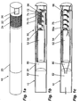
- FIGS. 1a to 1c show a first embodiment of an inhalation device 10 according to the invention.
- This is cylindrical in shape and has an outer wall 20, which at a distal end of the inhalation device 10 as the combustion chamber wall 22 with Micro perforations 24 is provided. At the distal end face, the wall 20 has a recess 26.
- FIG. 1b shows the internal structure of the inhalation device 10.
- a heater 50 is provided at the distal end of the inhalation device 10.
- the heater has a fuel storage 52, in which the fuel is stored in liquid.
- a wick 54 extends into a combustion chamber 56 which is provided at the distal end of the inhalation device and which is surrounded by the combustion chamber wall 22.
- the wick 54 is helically shaped.
- a total of three inhalable mixed generators 70 are arranged distributed over the circumference, each extending substantially axially from the distal end of the inhalation device in the direction of the proximal end.
- the inhalation mixture generator 70 are formed as hollow channels, in the air inlet openings 72 acting as flame barrier Glasmaschinepfropfen 74 are inserted.
- additives 76 are stored in a porous carrier.
- a homogenization chamber 80 At a proximal end of the inhalation mixture generator 70 is followed by a homogenization chamber 80, into which all three inhalation mixture generator 70 open.
- the proximal end of the inhalation device 10 is formed by a mouthpiece 82 with filter inserted, which completely fills the cross section of the outer wall 20.
- the Figure 1c illustrates the operation of the inhalation device 10.
- the inhalation device is inserted with its proximal end in the manner of a cigarette in the mouth. It is then ignited by holding an external flame, such as a lighter or a match, against the distal end of the inhalation device 10.
- an external flame such as a lighter or a match
- the wick 54 which is supplied from the fuel storage 52 with a fuel, for example with an alcohol.
- the combustion chamber 56 thereby forms a flame.
- the user Air may be drawn into the inhalation mixture generator 70 through the mouthpiece 82.
- the soaked air flows through the additives 76, which are stored in the porous carrier material. By heating the additives 76 are released to the incoming air and mix with this to an inhalation mixture.
- This inhalation mixture is drawn through the homogenization chamber 80 and the mouthpiece 82.
- the flame Due to the micro-perforations 24 in the outer wall 20 in the region of the combustion chamber 56, a high stability of the flame is achieved. In the absence of impairment, for example by wind, the flame is formed as a laminar flame in the region of the end face of the inhalation device. In the event that there is a strong flow of air at the distal end, for example due to wind or by a rapid movement of the inhalation device 10, a tearing of the laminar flame may result. In such a case, the flame may retreat into a more sheltered rear portion 56a of the combustion chamber 56, the air supply still being ensured through the micro-apertures 24.
- the illustrated and described inhalation device 10 has clear advantages over a normal cigarette in terms of a health burden on the user. While in a normal cigarette mitinhaliert a variety of undesirable additives, which are released in particular by the combustion of tobacco, inhaled in the illustrated inhaler 10 only the additives 76, which are particularly free of carcinogenic combustion products. Depending on the choice of additives 76, however, a similar taste and a similar effect with respect to the nicotine contained in cigarettes can be achieved.
- the inhaler device does not significantly alter the smoking of a cigarette Cigarette, the inhaler is ignited at its distal end and then remains in the inflamed state until the additives 76 are used up or the flame is extinguished. It may also be expedient to limit the amount of fuel in the fuel reservoir 52 in such a way that the fuel is used up at about the same time as the additives 76.
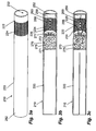
- FIGS. 2a to 2c show a second embodiment of an inhalation device according to the invention.
- This inhalation device 110 is in many ways the embodiment of the Fig. 1 similar. Unless stated otherwise below, their operation is the same.
- the inhalation device 110 has an outer wall 120, the front end of which is designed as a combustion chamber wall 122. Within this outer wall 120, a fuel reservoir 152, a combustion chamber 156 and an inhalable mixture generator 170 are provided.
- the inhalation mixture generator 170 and the fuel reservoir 152 differs from the embodiments of the Fig. 1 from. While the inhalation mixture generator 170 at the rear of the inhaler 110 occupies the complete cross-section, the mid-section of the inhalation mixture generator 170 divides into two semicircular cross-sectional areas, one occupied by the fuel reservoir 152 and the other by the inhalation mixture generator 170. This simplified structure is advantageous in terms of manufacturing costs.
- the inhalation mixture generator 170 has an outer wall. Depending on the configuration of the outer wall 120 of the inhalation device 110, however, such an additional wall can be dispensed with.
- the inhalation mixture generator 170 is made comparatively large in this embodiment and can thereby absorb larger amounts of flavorings, tobacco or the like.
- the combustion chamber 156 Significant differences exist with respect to the combustion chamber 156. In the embodiment of the Fig. 2a to 2c this is largely surrounded by the portion 122 of the outer wall 120, which is provided with a plurality of micro-apertures 124. At the distal end of the inhalation device 110, the outer wall 120 has an access opening 126. This is formed by an opening 126a which is concealed by a windscreen 126b in such a way that the air access is only possible by means of an intermediate circumferential gap 126c. The combustion chamber 156 is therefore accessible only indirectly from the outside through the access opening 126. This embodiment allows ignition of the flame in the combustion chamber by means of matches or lighter while pulling on the inhalation device 110.
- wicks 154a, 154b of fused silica of which only a long inner wick 154a and a short outer wick 154b are shown.
- the wicks each consist of quartz glass filaments with a diameter of 12.5 microns, wherein in each wick about 100 to 200 filaments are processed. But also fibers with a diameter of for example 50 to 100 micrometers can be used well.
- the wicks are surrounded by a protective film which prevents the fuel from escaping from the combustion chamber. In one embodiment, not shown, the wicks omitted. Instead, the fuel is in a gelatinous state.
- the inhalation device is ignited by a lighter or a match, which is held in the area of the gap 126c of the access opening 126 to the inhalation device 110.
- a lighter or a match By sucking in air, the flame of the lighter or match is drawn into the area of the longer wick 154a, where it leads to the ignition of the longer wick 154a.
- quartz glass As the material of the wick, due to the high melting point, particularly fine wicks 154a, 154b can be used. These lead to small flames with low oxygen demand.
- the flame burns mostly at the front end of the longer wick 154a, since the oxygen supply is best ensured there.
- air is drawn in through the microperforations 124 into the combustion chamber 156 at an increased rate. This results in spreading of the flame at the wick 154a toward the proximal end of the wick 154a. This results in the inflammation of the short wick 154b and possibly other similarly arranged wicks. This leads to an increase in the heat release to the air, so that even with strong inhalation by a user, the necessary heat can be provided by the flames in the combustion chamber.
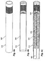
- a third embodiment is the Fig. 3a to 3c refer to.
- the illustrated inhaler 210 has a cylindrical shape with a shell-shaped outer wall 220. This is completed at the distal end by a cup-shaped fuel storage 252 made of chrome-nickel spring steel, wherein the fuel storage 252 contains a fuel 258 in a gel-like consistency and open in the direction of a combustion chamber 256 is.
- a cup-shaped fuel storage 252 made of chrome-nickel spring steel
- the fuel storage 252 contains a fuel 258 in a gel-like consistency and open in the direction of a combustion chamber 256 is.
- FIG Fig. 3b Prior to startup of the inhaler 210, as shown in FIG Fig. 3b As can be seen, the open side of the fuel reservoir 252 through a membrane 260 made of a material with low elasticity, for example by aluminum foil completed.
- the combustion chamber 256 is surrounded by micro-perforations 224 in a combustion chamber wall section 222 of the outer wall 220.
- an ignition access 226 is additionally provided, which consists of a total of four elongated openings, between which only narrow webs are provided.
- an inhalation mixture generator 270 On the proximal side of the combustion chamber 256 is followed by an inhalation mixture generator 270. This is formed as filled with a mixture 275 of tobacco and tobacco extract chamber, the combustion chamber side and user side is completed by walls 271 with inlet openings 272 and outlet openings, not shown.
- the fuel reservoir 252 is first slightly compressed from the outside. As a result, it deforms elastically, while the membrane 260 tears because of its low elasticity.
- the fuel 258 is thus accessible combustion chamber side, as in Fig. 3c is shown.
- the gel-like fuel 258 is ignited by means of a flame held externally to the access opening 226, so that a flame is formed in the combustion chamber 256, which is fed by fuel 258. This flame is very stable due to the partitioning of the combustion chamber 256.
- the micro-apertures 224 provide continuous reliable oxygen supply without any sudden gust of wind or the like annihilating them.
- the user pulling the mouthpiece 282 thereby draws the air heated to temperatures in excess of 250 ° C from the combustor 256 into the inhalation mixer generator 270. There, the hot air flows through the mixture 275, dissolving the additives that are subsequently inhaled by the user ,
- the smoking process is limited in time by the amount of fuel 258 and by the amount of additives in the mixture 275.
- the embodiment of the Fig. 4a to 4c corresponds largely to the embodiment of Fig. 3a to 3c , The only difference lies in the inhalation mixture generator 370.
- the inhalation device in the core consists only of the heater 350.
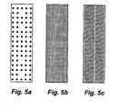
- the Fig. 5a to 5c show different combustion chamber walls in the unrolled state. These combustion chamber walls can be processed as separate components in the above-described and other inhalation devices or be part of larger outer walls which only partially form the combustion chamber wall.
- the illustrated wall sections are each 7 mm wide and 25 mm long strips, which offers a cylindrical combustion chamber wall of 7 mm in length and about 8 mm in diameter when finished.
- the total area of the combustion chamber walls is 1.75 cm 2 .
- Fig. 5a There are a total of 75 round micro perforations provided on this surface, each having an edge length of about 2 mm.
- the total edge length is therefore about 140 mm.
- the edge length is about 80 mm / cm 2 .
- the total edge length is about 1093 mm and the edge length related to the surface is about 625 mm / cm 2.
- Fig. 5c it is a total of about 150 line-shaped openings, each having an edge length of about 9 mm.
- the total edge length is therefore about 1350 mm and the edge area related to the surface is about 700 mm / cm 2.
Landscapes
- Health & Medical Sciences (AREA)
- Engineering & Computer Science (AREA)
- General Health & Medical Sciences (AREA)
- Anesthesiology (AREA)
- Biomedical Technology (AREA)
- Heart & Thoracic Surgery (AREA)
- Hematology (AREA)
- Life Sciences & Earth Sciences (AREA)
- Animal Behavior & Ethology (AREA)
- Public Health (AREA)
- Veterinary Medicine (AREA)
- Pulmonology (AREA)
- Bioinformatics & Cheminformatics (AREA)
- Chemical & Material Sciences (AREA)
- Chemical Kinetics & Catalysis (AREA)
- General Chemical & Material Sciences (AREA)
- Disinfection, Sterilisation Or Deodorisation Of Air (AREA)
- Thermotherapy And Cooling Therapy Devices (AREA)
- Portable Nailing Machines And Staplers (AREA)
- Cigarettes, Filters, And Manufacturing Of Filters (AREA)
- Lighters Containing Fuel (AREA)
- Agricultural Chemicals And Associated Chemicals (AREA)
- Cookers (AREA)
Description
- Die Erfindung betrifft eine Heizeinrichtung für eine Inhalationsvorrichtung zur inhalativen Einnahme eines Inhalationsgemisches aus Luft und mindestens einem Zusatzstoff mit einem Brennstoffspeicher, der mit einem thermisch brennbaren festen oder flüssigen Brennstoff befüllbar oder befüllt ist, und einer Brennkammer zur Verbrennung des Brennstoffs, die von der Umgebung durch eine Brennkammerwandung weitgehend abgeschlossen ist. Die Erfindung betrifft weiterhin eine Inhalationsvorrichtung zur inhalativen Einnahme eines Inhalationsgemisches aus Luft und mindestens einem Zusatzstoff mit einem Mundstück, einem Inhalationsgemischerzeuger mit einer Lufteinlassöffnung und einer Heizeinrichtung zur Verbrennung eines Brennstoffs und zur Erhitzung der Luft und/oder des Zusatzstoffs und/oder des Inhalationsgemisches, wobei der Inhalationsgemischerzeuger mit dem Mundstück unmittelbar oder über einen Inhalationskanal verbunden ist.
- Gattungsgemäße Inhalationsvorrichtungen sind aus dem Stand der Technik bekannt. Die Inhalationsvorrichtungen dienen insbesondere der Substitution normalen Tabakkonsums in Form von Zigaretten oder anderen Tabakwaren. Sie können darüber hinaus insbesondere bei der Entwöhnung von Rauchern verwendet werden. Dabei dienen gattungsgemäße Heizeinrichtungen zur Erwärmung der Luft oder der Zusatzstoffe.
- Aus der
US 5,099,861 A , derUS 4,969,476 A sowie derEP 0472367 A1 sind Inhalationsvorrichtungen bekannt, bei denen die Wärmeenergie durch ein glimmendes Kohleelement ohne Flamme zur Verfügung gestellt wird, wobei die entstehenden Verbrennungsgase durch den Benutzer mit inhaliert werden. Aus derDE 2704218 A1 ist ein Gerät bekannt, bei welchem ein Heizelement durch die Flamme einer Heizquelle, beispielsweise eines Feuerzeugs erhitzt wird. Aus derUS 6,164,287 A und derJP 2000 236 865 A DE 19854009 A1 ist eine Inhalationsvorrichtung bekannt, bei der ein Heizmittel, insbesondere Propangas, in einer geschlossenen Brennkammer verbrannt wird. Aus derUS 6,532,965 B1 sind Inhalationsvorrichtungen bekannt, bei denen Ethanol in einer Brennkammer verbrennt. Aus derUS 6,598,607 B2 und derUS 5,944,025 A sind Inhalationsvorrichtungen bekannt, bei denen Ethanol in einer katalytischen Reaktion ohne Flamme verbrennt. - Als nachteilig am Stand der Technik wird angesehen, dass die Handhabung der bekannten Inhalationsvorrichtungen sich deutlich von der einem Raucher bekannten üblichen Handhabung einer Zigarette unterscheidet, die Flamme in der Brennkammer nicht ausreichend stabil brennt und/oder die Stabilisierung des Verbrennungsprozesses aufwändige technische Maßnahmen erfordert.
- Aufgabe der Erfindung ist es, gattungsgemäße Heizeinrichtungen und Inhalationsvorrichtungen in Hinblick auf eine unkomplizierte Handhabung und zuverlässige Funktionsweise weiterzubilden.
- Erfindungsgemäß wird dies durch eine gattungsgemäße Heizeinrichtung mit den kennzeichnenden Merkmalen des Anspruchs 1 erreicht.
- In der Brennkammer der Heizeinrichtung wird der dorthin geförderte oder direkt dort gelagerte Brennstoff mit einer Flamme verbrannt. Vorzugsweise ist die Heizeinrichtung derart ausgebildet, dass nach Entzünden keine Energiezufuhr von außen zur Aufrechterhaltung der Flamme mehr erforderlich ist. Die erzeugte Wärme wird in einem der Heizeinrichtung zugeordneten Inhalationsgemischerzeuger genutzt, um ein zu inhalierendes Aerosol zu erzeugen. Die Nutzung der Wärme kann durch eine Erwärmung von Luft vor dem Eintreten in einen Inhalationsgemischerzeuger und/oder durch eine unmittelbare Erwärmung der zu inhalierenden Zusatzstoffe erfolgen.
- Zur Integration der Heizeinrichtung in einer Inhalationsvorrichtung, die bezüglich ihrer Größe die Größe einer Zigarette nicht wesentlich übersteigt, ist die Heizeinrichtung in zwei der drei Dimensionen vorzugsweise kleiner als 11 mm.
- Die Brennkammer weist einen freien Ausbreitungsbereich für die Flamme auf, der einen Durchmesser von mindestens 5 mm, vorzugsweise von mindestens 7 mm, aufweist. Vorzugsweise ist die Brennkammer zylindrisch ausgebildet und weist einen Durchmesser von mindestens 7 mm und eine Länge von mindestens 7 mm auf.
- Als Brennkammer gilt der Raum, in dem sich die Flamme bei Gebrauch der Heizeinrichtung bestimmungsgemäß entfalten kann. Die Brennkammerwandung ist die Wandung, die die Brennkammer von einer Außenumgebung trennt, aus der der Sauerstoff zur Verbrennung stammt. Wandungen zu einem angrenzenden Inhalationsgemischerzeuger oder dem Brennstoffspeicher sind nicht Teil der Brennkammerwandung.
- Die Angaben über die Randlängen der Mikrodurchbrechungen beziehen sich auf den Abschnitt der Brennkammerwandung, in dem die Mikrodurchbrechungen vorgesehen sind. Vorzugsweise sind die Mikrodurchbrechungen weitgehend homogen über die Brennkammerwandung verteilt. Sofern die Randlängendichte über die Brennkammerwandung variiert, beziehen sich die hier gemachten Angaben über die Randlängendichte auf einen Abschnitt der Brennkammerwandung, in dem sich bei relativ höchster Randlängendichte 80% der Mikrodurchbrechungen befinden.
- Die Mikrodurchbrechungen, die in regelmäßiger, beispielsweise matrixartiger, oder in unregelmäßiger Anordnung vorgesehen sein können, gewährleisten eine kontinuierliche Sauerstoffversorgung der Flamme durch die Brennkammerwandung und ermöglichen dadurch eine Aufrechterhaltung der Flamme während der gesamten Nutzungsdauer. Bei einer besonderen Ausführungsform können die Mikrodurchbrechungen in Form von Schriftzeichen angeordnet sein, so dass Markenzeichen und ähnliches ohne Druckprozess aufgebracht werden können.
- Die geringe Größe der Durchbrechungen schützt die Flamme vor äußeren Luftbewegungen und stabilisiert somit den Verbrennungsprozess. Die Ränder der Durchbrechungen erzeugen im Falle von Windstößen Wirbel in der Brennkammerwandung, welche die durchströmende Luft abbremsen. Aus aerodynamischer Sicht ist daher die Randlänge der Durchbrechungen maßgebend für den Strömungswiderstand der Brennkammerwandung. Bei gleicher offener Fläche führt eine höhere Randlänge pro Fläche zu einer Erhöhung des Strömungswiderstandes der Brennkammerwandung. Dadurch wird im Falle eines Windstoßes die Luftbewegung innerhalb der Brennkammer verringert, welche zu einem Erlöschen der Flamme führen könnte. Mikrodurchbrechungen mit hohen Randlängendichten ermöglichen daher im Gegensatz zu großen Durchbrechungen eine Stabilisierung der Flamme.
- Als Rand der Mikrodurchbrechungen wird im Zusammenhang mit dieser Erfindung der Übergangsbereich zwischen Brennkammerwandung und Mikrodurchbrechung verstanden, wobei die entsprechenden Längenangaben auf ein optisches Auflösungsvermögen mit einer maximalen Auflösung von 5 Mikrometer bezogen sind. Die Längenangaben beziehen sich bei Mikrodurchbrechungen, die senkrecht zur Erstreckungsrichtung der Wandung verlaufen, auf eine plane Projektion. Bei Mikrodurchrechungen, die nicht senkrecht zur Erstreckungsrichtung der Wandung verlaufen, z.B. bei Verwendung einer Tresse, wird die absolute Filterfeinheit zur Bestimmung der Randlängen der Durchbrechungen herangezogen. Maßgebend für die Randlängenermittlung ist dementsprechend die maximale Randlänge eines Objektes, welches durch die jeweilige Mikrodurchbrechung passt.
- Zur Zuführung des Brennstoffs in die Brennkammer kann ein Docht oder ein Druckrohr vorgesehen sein. Der Docht bzw. das Druckrohr können vorzugsweise mit einer oder mehreren der nachfolgenden Eigenschaften ausgebildet sein. Der Docht kann als Glasfaserdocht ausgebildet sein, der durch Kapillarkräfte den flüssigen Brennstoff in die Brennkammer fördert. Die Erweichungstemperatur des Dochts oder seines überwiegenden Teils kann über 800° C, vorzugsweise über 1000° C, liegen, um eine dünne Gestaltung des Dochts und damit einen geringen Sauerstoffbedarf der Flamme zu ermöglichen. Ein solcher Docht kann beispielsweise aus Quarzglas bestehen. Der Docht kann zur Vermeidung von Übergangsverlusten selbst den Brennstoffspeicher darstellen und zu diesem Zweck einen vorzugsweise Platz sparend zusammengelegten Brennstoffspeicherabschnitt aufweisen. Es können mehrere Dochte vorgesehen sein, die sich verschieden weit in die Brennkammer erstrecken, um eine Aufrechterhaltung der Flamme auch nach Erlöschen eines der Dochte oder eine stärkere Hitzeentwicklung durch mehrere Flammen bei starker Stauerstoffzufuhr zu ermöglichen.
- Besondere Ausführungsformen sehen vor, dass im Bereich der Brennkammer mindestens ein dünnes Glühelement vorgesehen ist, welches durch die Flamme zum Glühen gebracht werden kann. Das Glühelement macht einen Betriebszustand der Heizeinrichtung sichtbar, was insbesondere bei Brennstoffen mit nicht sichtbarer Flamme zweckmäßig ist. Das Glühelement ist vorzugsweise als Chromnickeldraht ausgebildet.
- Die Mikrodurchbrechungen sind vorzugsweise bezogen auf die Verwendung in einer zylindrischen Inhalationsvorrichtung an einer seitlichen Mantelwandung der Brennkammer vorgesehen. Vorzugsweise ist ein Bereich der Mikrodurchbrechungen in der Mantelwandung vorgesehen, der sich in Haupterstreckungsrichtung der Inhalationsvorrichtung über eine Länge zwischen 5 mm und 20 mm erstreckt.
- Die Randlängendichte ist die Summe der Randlängen der Mikrodurchbrechungen pro Fläche. Die Randlängendichte wird ermittelt durch Bestimmung der Randlänge jeder einzelnen Durchbrechung, anschließende Aufsummierung über alle Durchbrechungen und Division durch die Fläche, auf der sich die Durchbrechungen verteilen.
- Besonders vorteilhaft sind Mikrodurchbrechungen hinsichtlich des Einströmverhaltens der Luft und des Schutzes der Flamme, wenn die Randlängendichte mehr als 120 mm / cm2, insbesondere mehr als 200 mm / cm2 beträgt. Vorzugsweise beträgt die Randlängendichte über 400 mm / cm2, insbesondere über 800 mm / cm2. Die Gesamtrandlänge sollte mindestens bei 140 mm, insbesondere über 210 mm liegen. Vorzugsweise liegt die Gesamtrandlänge bei über 350 mm, vorzugsweise bei 700 mm, insbesondere über 1400 mm.
- Als besonders bevorzugte Kombination hat sich eine Gesamtrandlänge von 140 mm bei einer Randlängendichte von 80 mm / cm2 herausgestellt. Noch vorteilhafter sind 210 mm oder mehr Gesamtrandlänge bei 120 mm / cm2 oder höherer Randlängendichte, beispielsweise 350 mm bei 200 mm / cm2, 700 mm bei 400 mm / cm2, 1400 mm bei 800 mm / cm2. Eine höhere Randlängendichte und eine höhere Gesamtrandlänge werden jeweils als vorteilhaft angesehen. Weiterhin von Vorteil ist es dabei, wenn gegenüberliegende Ränder einer Mikrodurchbrechung maximal 1,4 mm voneinander beabstandet sind, um ein Hindurchdringen der Flamme zu vermeiden. Die Formgebung der Mikrodurchbrechungen kann verschieden geartet sein. Besonders einfach sind runde und quadratische Mikrodurchbrechungen herstellbar. Auch andere Formgebungen wie längliche, linienförmige oder schlangenlinienförmige Durchbrechungen sind geeignet.
- Die Mikrodurchbrechungen selbst weisen bei einer Weiterbildung der Erfindung eine durchschnittliche Öffnungsfläche von weniger als 1,5 mm2, vorzugsweise eine Öffnungsfläche von weniger als 1 mm2, insbesondere vorzugsweise eine Öffnungsfläche von weniger als 0,5 mm2 auf. Sie weisen darüber hinaus vorzugsweise eine Öffnungsfläche von mehr als 0,0002 mm2, insbesondere mehr als 0,0004 mm2 auf. Derartige Öffnungsflächen sind in Hinblick auf die Sauerstoffzufuhr und eine Vermeidung nachteiliger Luftstöße bis in die Brennkammer von Vorteil.
- Der offene Bereich der Brennkammerwandung, der durch die Mikrodurchbrechungen geschaffen wird, nimmt vorzugsweise zwischen 10% und 50%, insbesondere zwischen 20% und 45% des Abschnitts der Brennkammerwandung ein, in dem die Mikrodurchbrechungen vorgesehen sind.
- In einer Weiterbildung der Erfindung wird die Brennkammerwandung zumindest zum Teil durch ein Metallgewebe oder Metallgeflecht gebildet. Als vorteilhaft haben sich Metallgewebe und -geflechte mit einem Mesh-Wert zwischen 150 und 635, Metallgewebe und -geflechte mit einer Maschenweite zwischen 0,02 mm und 0,08 mm und/oder Metallgewebe und -geflechte mit einer Drahtstärke zwischen 0,019 mm und 0,05 mm herausgestellt.
- Alternativ dazu kann auch die Ausbildung der Brennkammerwandung als Metallfolie mit eingebrachten Mikrodurchbrechungen von Vorteil sein. Die Mikrodurchbrechungen können dabei beispielsweise mechanisch oder mittels Ätzverfahren eingebracht werden.
- Besonders bevorzugt sind Ausführungsformen, bei denen das Wandungsmaterial dünn ist und/oder eine relativ geringe Wärmekapazität aufweist. Dies führt dazu, dass die im Zuge des Entzündens eingebrachte Wärme nicht zur Erhitzung der Wandung abgeführt wird, sondern fast ausschließlich dem Entzünden dient. Eine leichtere Entzündbarkeit der Flamme in der Brennkammer ist die Folge. Bei Verwendung eines Metallgewebes oder einer Metallfolie als Wandungsmaterial, beispielsweise aus Chrom-Nickelstahl, sollte das Flächengewicht unter 300 Gramm/m2 liegen.
- In einer Weiterbildung der Erfindung ist die Brennkammer nur im Bereich mindestens und vorzugsweise eines Zündungszugangs von außen zugänglich. Die Zugänglichkeit ist dabei so zu verstehen, dass nur durch den Zündungszugang eine Anzündflamme beim Entzünden der Heizeinrichtung hindurchgelangen kann. Als Zündungszugang wird ein zusammenhängender Flächenbereich von mindestens 2 mm2 angesehen, der zumindest zu 90% frei ist und einen offenen Kanal zwischen Umgebung und Brennkammer bildet. Vorzugsweise ist der Zündungszugang als länglicher Schlitz ausgebildet, der mindestens 1 mm breit ist. Der Zündungszugang ist bei einer bevorzugten Variante in einer seitlichen Wandung der Brennkammer vorgesehen. Alternativ kann der Zündungszugang auch am distalen Ende der Heizeinrichtung bezogen auf ihren mit einer Inhalationsvorrichtung verbundenen Zustand angeordnet sein. Vorzugsweise ist der Zündungszugang durch hintereinander angeordnete und/oder gegeneinander versetzte Flächenabschnitte so ausgebildet, dass die Luft beim Eindringen in die Brennkammer wenigstens einmal umgelenkt wird.
- Als Brennstoff eignet sich insbesondere ein Ethanol-Wasser-Gemisch, da Ethanol eine nahezu vollständige Verbrennung ermöglicht, leicht entzündbar und nicht toxisch ist. Es können jedoch auch andere Brennstoffe Verwendung finden, wobei auch die Verwendung von toxischen Brennstoffen möglich ist, sofern die eingesogene Luft örtlich getrennt von der Brennkammer in die Vorrichtung eingesogen wird. Neben Ethanol haben sich andere Alkohole, Aldehyde, Ketone, Ester, n-Alkane mit einem bis vier Kohlenstoffatomen, n-Alkane mit fünf bis zwanzig Kohlenstoffatomen, verzweigte oder ringförmige Alkane mit vier bis zwanzig Kohlenstoffafomen, als zweckmäßig herausgestellt.
- In einer Weiterbildung der Erfindung wird ein flüssiger Brennstoff mit einer Viskosität von mindestens 10.000 mPa·s verwendet. Die Flamme in der Brennkammer erhitzt die Oberfläche dieses Brennstoffgels über den Siedepunkt des Brennstoffs hinaus. Dadurch wird an der Oberfläche des Brennstoffgels Brennstoff verdampft und für den Erhalt der Flamme kontinuierlich bereitgestellt. Das Brennstoffgel gestattet eine einfache Handhabung und erlaubt darüber hinaus eine Anordnung unmittelbar in der Brennkammer und dadurch den Verzicht auf Dochte. Bei geringviskosen Brennstoffen kann durch den Zusatz von viskositätserhöhenden Additiven wie Polyacrylsäure oder Cellulose die gewünschte Viskosität erreicht werden.
- Bei einer Weiterbildung der Erfindung ist der Brennstoffspeicher mittels eines gasdichten Verschlusses verschlossen, der durch Wärmezuführung entfernbar ist. Dadurch wird verhindert, dass sich der Brennstoff schon vor dem Entzünden verflüchtigt. Eine Entfernung des Verschlusses wird durch eine Wärmezuführung im Zuge der Entzündung der Flamme der Inhalationsvorrichtung erreicht. Als Materialien für den Verschluss kommen beispielsweise behandeltes Papier, Wachs, Zinnfolie oder Kunststofffolie in Betracht.
- Alternativ hierzu kann vorgesehen sein, dass der Brennstoffspeicher mittels eines gasdichten Verschlusses verschlossen ist, der durch manuell aufbringbaren Druck auf den Brennstoffspeicher, vorzugsweise durch beidseitigen Druck auf die Heizeinrichtung im Bereich des Brennstoffspeichers, entfernbar oder aufreißbar ist. Ein solcher gasdichter Verschluss kann insbesondere eine Folie sein, die an einem Auslass eines ansonsten formstabilen Brennstofftanks vorgesehen ist. Der Benutzer kann die Heizeinrichtung bei einer Ausgestaltung gemäß dieser Weiterbildung durch einen leichten Druck in einen verwendbaren Zustand überführen.
- Besonders vorteilhaft ist es, wenn eine Außenwandung des Brennstoffspeichers elastisch stark verformbar ist und durch eine Verschlussfolie abgeschlossen ist, die in geringerem Maße elastisch verformbar ist. Eine gemeinsame Verformung der Wandung und der Verschlussfolie führt dazu, dass die Verschlussfolie nach Erreichen der Reißgrenze aufreißt. Nach Wegfall der Verformungskraft kehrt der Brennstoffspeicher in seine ursprüngliche Form zurück und gestattet dann das Entweichen des Brennstoffs durch die gerissene Verschlussfolie.
- Bei einer Weiterbildung der Erfindung ist der Brennstoffspeicher lösbar mit der Heizeinrichtung verbindbar und/oder wiederauffüllbar. Dies gestattet es, den Brennstoffspeicher wiederaufzufüllen oder austauschbar zu gestalten, wodurch andere Komponenten der Heizeinrichtung, insbesondere die Brennkammer mehrfach verwendet werden können.
- Die Erfindung betrifft weiterhin eine gattungsgemäße Inhalationsvorrichtung, bei der die Heizeinrichtung nach oben beschriebener Art ausgebildet ist.
- Durch das Mundstück, das beispielsweise als Hohlrohr oder Filter ausgebildet sein kann, kann der Benutzer Luft einsaugen, die dabei durch den Inhalationsgemischerzeuger geführt wird und dort mit mindestens einem Zusatzstoff vermengt wird. Das Gemisch wird nachfolgend vom Benutzer inhaliert.
- Die Vermengung der Luft mit den Zusatzstoffen wird durch die hohe Temperatur der in der Brennkammer erhitzten Luft und/oder der erhitzten Zusatzstoffe erreicht. Es bildet sich dadurch ein inhalierbares Aerosol aus der eingesogenen Luft und den Zusatzstoffen. Durch die Wärme wird auch die Trennung der Zusatzstoffe von einer Trägerstruktur erreicht, in der die Zusatzstoffe gelagert sind. Die Wärme kann weiterhin eine chemische Modifikation der Zusatzstoffe und/oder der Trägerstruktur bewirken.
- Die in der Brennkammer erzeugte Wärme wird vorzugsweise unmittelbar dem Inhalationsgemischerzeuger und/oder der eingesogenen Luft zugeführt, wobei die Flamme in der Brennkammer den Inhalationsgemischerzeuger und/oder die Luft unmittelbar oder mittelbar über wärmeleitende Materialien erwärmen kann. Um zu verhindern, dass die Flamme in der Brennkammer mit der Luft bis in den Inhalationsgemischerzeuger eingesogen wird, kann vor dem Inhalationsgemischerzeuger eine Flammenbarriere, beispielsweise aus Metallfolie, vorgesehen sein.
- Die Zusatzstoffe sind vor der Vermengung mit der durchströmenden Luft vorzugsweise bereits in einem Zusatzstoffspeicher innerhalb des Inhalationsgemischerzeugers gelagert. Alternativ können sie in einem räumlich getrennten Zusatzstoffspeicher gelagert sein. Die Zusatzstoffe sind vorzugsweise in einem porösen Trägermaterial gelagert, wobei sich hierfür insbesondere Aktivkohle, Aluminiumoxid, Calciumkarbonat, Kieselgur, Zellulose oder Tabakmaterial anbieten. Zweckmäßig kann auch eine Lagerung der Zusatzstoffe in Pflanzenteilen sein, insbesondere in den Pflanzenteilen, die die Zusatzstoffe natürlich hervorbringen. Dies ist insbesondere bei Tabak mit Nikotin oder bei Heilkräutern mit Wirkstoffen zweckmäßig. Der Zusatzstoffspeicher kann durch eine Zigarette oder eine zumindest teilweise ummantelte oder anderweitig zusammengefügte Tabakeinheit gebildet werden. Bei Inhalationsgemischerzeugern mit mehreren Zusatzstoffen sind diese vorzugsweise hintereinander angeordnet, wobei hitzeempfindlichere Zusatzstoffe in einem hinteren Bereich des Strömungswegs der Luft angeordnet sind.
- Die Brennkammer ist vorzugsweise so ausgebildet und in der Inhalationsvorrichtung angeordnet, dass die Flamme von außen sichtbar ist. Sie ist vorzugsweise derart zugänglich, dass ein Entzünden der Flamme mit den herkömmlicherweise bei Zigaretten üblichen Mitteln wie Streichhölzern oder Feuerzeugen von außen möglich ist.
- Die Komponenten der Inhalationsvorrichtung sind vorzugsweise in einem einheitlichen Gehäuse mit einer gemeinsamen Außenwandung angeordnet. Dabei ist es besonders vorteilhaft, wenn die Formgebung des Gehäuses an übliche Tabakwaren wie an eine Zigarette angenähert ist. Bevorzugt werden Ausführungsformen, bei denen die Außenwandung zumindest zum Teil aus nicht oder schwer entflammbarem Material besteht, beispielsweise aus vorbehandeltem Papier, aus Metall, aus Keramik oder aus Porzellan.
- Der Haupteinsatzzweck erfindungsgemäßer Inhalationsvorrichtungen ist der Ersatz üblicher Tabakwaren, bei denen die Wirkstoffe und Zusatzstoffe durch eine Verbrennung von Tabak freigesetzt werden. Bei einer erfindungsgemäßen Inhalationsvorrichtung können die Zusatzstoffe unter Vermeidung krankheitserzeugender, insbesondere krebserzeugender Zusatzstoffe und Verbrennungsprodukte sehr gezielt ausgewählt werden. So bieten sich für einen Zigarettenersatz insbesondere Zusatzstoffkombination mit dem Wirkstoff Nikotin und Aromastoffen an. Als geschmacksbildende Zusatzstoffe sind insbesondere Öle, Tabakpflanzenextrakte sowie natürliche und naturidentische Aromastoffe zweckmäßig. Darüber hinaus sind zur Nachahmung herkömmlicher Zigaretten auch vorzugsweise geschmacksneutrale nebelerzeugende Substanzen wie Polyole, insbesondere Propylenglycol oder Glycerol, zweckmäßig. Es kann aber auch herkömmlicher Tabak Verwendung finden, dessen Schädlichkeit durch die Vermeidung einer Verbrennung des Tabaks erheblich gesenkt wird.
- Neben der Verwendung als Ersatz herkömmlicher Tabakwaren sind auch andere Anwendungen möglich, beispielsweise medizinische Anwendungen, bei denen der Zusatzstoff eine insbesondere pharmazeutische Wirkung hat. Dies umfasst zum Beispiel Schmerzmittel und Beruhigungsmittel.
- Bei einer Weiterbildung ist die Heizeinrichtung als separat handhabbare Vorrichtung ausgebildet, die mit dem Inhalationsgemischerzeuger lösbar verbindbar ist. Dies gestattet es, die Heizeinrichtung wiederzuverwenden, während der Inhalationsgemischerzeuger, vorzugsweise gemeinsam mit dem Mundstück und einem Zusatzstoffspeicher, als Einweg-Komponente gehandhabt wird. Insbesondere können die Komponenten Mundstück, Inhalationsgemischerzeuger und Zusatzstoffspeicher auch gemeinsam durch eine handelsübliche Zigarette oder eine abgepackte Tabakeinheit mit Mundstück gebildet sein, an der die Heizeinrichtung derart anbringbar ist, dass die durch die Zigarette oder die Tabakeinheit eingesogenen Luft mittels der Flamme in der Brennkammer der Heizeinrichtung erhitzt wird. Eine solche Heizeinrichtung wird vorzugsweise am distalen, also dem Benutzer abgewandten Ende, auf die Zigarette oder die Tabakeinheit aufgesetzt.
- Zweck dieser Kombination aus Heizeinrichtung und derartigem Tabakerzeugnis ist es, dem Tabakerzeugnis Wärme aus der Heizeinrichtung zuzuführen, um eine Trennung der Wirkstoffe und/oder Geschmackstoffe von dem Tabak zu erreichen. Die in der Brennkammer erzeugte Wärme wird durch Konvektion und/oder Wärmeleitung dem Tabak zugeführt und erwärmt diesen auf 150°C bis 400°C. Dadurch werden die Zusatzstoffe aus dem Tabak gelöst, ohne dass es zu einer Entzündung des Tabakerzeugnisses kommt. Der Benutzer kann sein gewohntes Tabakerzeugnis weiterverwenden, wobei dessen schädigende Eigenschaften verringert werden. Im Falle einer derartigen Heizeinrichtung, die für die Verwendung mit einer normalen Zigarette geeignet ist, wäre der Aufsatz vorzugsweise so auszubilden, dass er den Abschnitt der Zigarette, der mit Tabak befüllt ist, vollständig oder weitgehend umschließt. Denkbar sind auch Ausführungsformen, bei denen auch das Mundstück Teil des Aufsatzes ist, so dass von der Zigarette lediglich der Tabak genutzt wird. Bei einer Weiterbildung der Erfindung lässt sich die Heizeinrichtung auf die Lufteinlassöffnung einer Pfeife aufsetzen.
- Bei einer Weiterbildung der Inhalationsvorrichtung ist ein vom Inhalationsgemischerzeuger getrennt ausgebildeter Zusatzstoffspeicher vorgesehen, wobei der Zusatzstoffspeicher austauschbar und/oder wiederbefüllbar ausgebildet ist. Die Austauschbarkeit des Zusatzstoffspeichers ermöglicht es, bestimmte Bestandteile, wie beispielsweise das Gehäuse, die Heizeinrichtung und/oder das Mundstück wiederholt zu verwenden. Der Zusatzstoffspeicher kann an die Inhalationsvorrichtung in einfacher Art und Weise angesteckt oder in die Inhalationsvorrichtung eingesetzt werden.
- Bei einer Weiterbildung der Erfindung weist die Inhalationsvorrichtung eine im Wesentlichen längliche Struktur, vorzugsweise eine zylindrische Struktur auf, wobei das Mundstück an einem proximalen Ende der Inhalationsvorrichtung angeordnet ist und wobei die Heizeinrichtung im Bereich des distalen Endes der Inhalationsvorrichtung angeordnet ist. Eine solche Inhalationsvorrichtung kommt bezüglich der Formgebung einer Zigarette bzw. Zigarre besonders nahe und bildet somit einen guten Zigarettenersatz.
- Weitere Vorteile und Merkmale der Erfindung ergeben sich aus den Ansprüchen sowie der nachfolgenden Beschreibung von bevorzugten Ausführungsbeispielen der Erfindung, die anhand der Zeichnungen dargestellt ist. Die Ausführungsbeispiele dienen nur der Erläuterung und schränken die Erfindung nicht ein. Es zeigt:
- Fig. 1 a bis 1 c
- eine erste Ausführungsform einer erfindungsgemäßen Inhalationsvorrichtung in einer ungeschnittenen und einer geschnittenen Ansicht sowie in einem Betriebs- zustand,
- Fig. 2a bis 2c
- eine zweite Ausführungsform einer erfindungsgemä- ßen Inhalationsvorrichtung in einer ungeschnittenen und einer geschnittenen Ansicht sowie in einem Be- triebszustand,
- Fig. 3a bis 3c
- eine dritte Ausführungsform einer erfindungsgemäßen Inhalationsvorrichtung in einer ungeschnittenen und einer geschnittenen Ansicht sowie in einem Betriebs- zustand,
- Fig. 4a bis 4c
- eine vierte Ausführungsform einer erfindungsgemä- ßen Inhalationsvorrichtung in einer ungeschnittenen und einer geschnittenen Ansicht sowie in einem Be- triebszustand und
- Fig. 5a bis 5c
- verschiedene Brennkammerwandungen im abgeroll- ten Zustand.
- Im Zusammenhang mit der Erfindung wird unter dem proximalen Ende stets das dem Benutzer zugewandte Ende einer Komponente verstanden und unter dem distalen Ende das vom Benutzer weggewandte. Bezüglich ihrer Funktion vergleichbare Komponenten der verschiedenen Ausführungsbeispiele stimmen in den letzten beiden Ziffern des Bezugszeichens überein.
- Die
Figuren 1a bis 1c zeigen eine erste Ausführungsform einer erfindungsgemäßen Inhalationsvorrichtung 10. Diese ist zylinderförmig ausgebildet und weist eine Außenwandung 20 auf, die an einem distalen Ende der Inhalationsvorrichtung 10 als Brennkammerwandung 22 mit Mikrodurchbrechungen 24 versehen ist. An der distalen Stirnseite weist die Wandung 20 eine Aussparungen 26 auf. -
Figur 1b zeigt den inneren Aufbau der Inhalationsvorrichtung 10. Am distalen Ende der Inhalationsvorrichtung 10 ist eine Heizeinrichtung 50 vorgesehen. Die Heizeinrichtung weist einen Brennstoffspeicher 52 auf, in dem der Brennstoff flüssig gelagert ist. Aus dem Brennstoffspeicher 52 erstreckt sich ein Docht 54 in eine Brennkammer 56, die am distalen Ende der Inhalationsvorrichtung vorgesehen ist und die von der Brennkammerwandung 22 umgeben wird. Der Docht 54 ist schraubenartig geformt. An einer Innenseite der Außenwandung 20 sind über den Umfang verteilt insgesamt drei Inhalationsgemischerzeuger 70 angeordnet, die sich jeweils im Wesentlichen axial vom distalen Ende der Inhalationsvorrichtung ausgehend in Richtung des proximalen Endes erstrecken. Die Inhalationsgemischerzeuger 70 sind als Hohlkanäle ausgebildet, in deren Lufteinlassöffnungen 72 als Flammenbarriere wirkende Glasfaserpfropfen 74 eingefügt sind. In den röhrenförmigen Inhalationsgemischerzeugern 70 sind Zusatzstoffe 76 in einer porösen Trägersubstanz gelagert. An einem proximalen Ende der Inhalationsgemischerzeuger 70 schließt sich an diese eine Homogenisierungskammer 80 an, in die alle drei Inhalationsgemischerzeuger 70 münden. Das proximale Ende der Inhalationsvorrichtung 10 wird durch ein Mundstück 82 mit eingesetztem Filter gebildet, der den Querschnitt der Außenwandung 20 vollständig ausfüllt. - Die
Figur 1c verdeutlicht die Funktionsweise der Inhalationsvorrichtung 10. Die Inhalationsvorrichtung wird mit ihrem proximalen Ende in der Art einer Zigarette in den Mund gesteckt. Sie wird dann entzündet, indem eine externe Flamme, beispielsweise von einem Feuerzeug oder einem Streichholz, an das distale Ende der Inhalationsvorrichtung 10 gehalten wird. Dadurch entzündet sich der Docht 54, der aus dem Brennstoffspeicher 52 mit einem Brennstoff, beispielsweise mit einem Alkohol versorgt wird. In der Brennkammer 56 bildet sich dadurch eine Flamme. Der Benutzer kann Luft durch das Mundstück 82 in die Inhalationsgemischerzeuger 70 einsaugen. Die eingesogene Luft durchströmt die Zusatzstoffe 76, die in dem porösen Trägermaterial gespeichert sind. Durch die Erwärmung werden die Zusatzstoffe 76 an die einströmende Luft abgegeben und vermengen sich mit dieser zu einem Inhalationsgemisch. Dieses Inhalationsgemisch wird durch die Homogenisierungskammer 80 und das Mundstück 82 gesogen. - Durch die Mikrodurchbrechungen 24 in der Außenwandung 20 im Bereich der Brennkammer 56 wird eine hohe Stabilität der Flamme erreicht. Bei Fehlen einer Beeinträchtigung, beispielsweise durch Wind, ist die Flamme als laminare Flamme im Bereich der Stirnseite der Inhalationsvorrichtung ausgebildet. Im Falle, dass es am distalen Ende zu einer starken Luftströmung, beispielsweise durch Wind oder durch eine schnelle Bewegung der Inhalationsvorrichtung 10 kommt, kann eine Abreißen der laminaren Flamme die Folge sein. In einem solchen Fall kann sich die Flamme in einen windgeschützteren hinteren Bereich 56a der Brennkammer 56 zurückziehen, wobei die Luftzuführung dann immer noch über die Mikrodurchbrechungen 24 gewährleistet ist.
- Die dargestellte und beschriebene Inhalationsvorrichtung 10 weist gegenüber einer normalen Zigarette deutliche Vorteile in Hinblick auf eine Gesundheitsbelastung des Benutzers auf. Während bei einer normalen Zigarette eine Vielzahl an unerwünschten Zusatzstoffen mitinhaliert werden, die insbesondere durch die Verbrennung des Tabaks freigesetzt werden, werden bei der dargestellten Inhalationsvorrichtung 10 lediglich die Zusatzstoffe 76 inhaliert, die insbesondere frei sind von krebserzeugenden Verbrennungsprodukten. Je nach Wahl der Zusatzstoffe 76 kann dennoch ein ähnlicher Geschmack sowie eine ähnliche Wirkung in Hinblick auf das in Zigaretten enthaltene Nikotin erzielt werden.
- Die Verwendung der Inhalationsvorrichtung stellt verglichen mit dem Rauchen einer Zigarette keine wesentlichen Änderungen dar. Wie eine Zigarette wird die Inhalationsvorrichtung an ihrem distalen Ende entzündet und bleibt dann im entzündeten Zustand, bis die Zusatzstoffe 76 aufgebraucht sind oder die Flamme zum Erlöschen gebracht wird. Es kann auch zweckmäßig sein, die Brennstoffmenge im Brennstoffspeicher 52 derart zu begrenzen, dass der Brennstoff in etwa gleichzeitig mit den Zusatzstoffen 76 aufgebraucht ist.
- Die
Figuren 2a bis 2c zeigen eine zweite Ausführungsform einer erfindungsgemäßen Inhalationsvorrichtung. Diese Inhalationsvorrichtung 110 ist in vielerlei Hinsicht der Ausführungsform derFig. 1 ähnlich. Soweit im Folgenden nichts anderes angegeben ist, ist ihre Funktionsweise die gleiche. - Die Inhalationsvorrichtung 110 weist eine Außenwandung 120 auf, deren vorderes Ende als Brennkammerwandung 122 ausgebildet ist. Innerhalb dieser Außenwandung 120 sind ein Brennstoffspeicher 152, eine Brennkammer 156 sowie ein Inhalationsgemischerzeuger 170 vorgesehen.
- Die Anordnung des Inhalationsgemischerzeugers 170 und des Brennstoffspeichers 152 weicht von den Ausführungsformen der
Fig. 1 ab. Während der Inhalationsgemischerzeuger 170 im hinteren Bereich der Inhalationsvorrichtung 110 den vollständigen Querschnitt einnimmt, teilt sich der Querschnitt im mittleren Bereich des Inhalationsgemischerzeugers 170 in zwei halbkreisförmigen Querschnittsbereiche auf, wobei der eine vom Brennstoffspeicher 152 und der andere vom Inhalationsgemischerzeuger 170 eingenommen wird. Dieser vereinfachte Aufbau ist in Hinblick auf die Herstellungskosten von Vorteil. Bei der dargestellten Ausführungsform weist der Inhalationsgemischerzeuger 170 eine Außenwandung auf. Je nach Ausgestaltung der Außenwandung 120 der Inhalationsvorrichtung 110 kann auf eine solche zusätzliche Wandung jedoch verzichtet werden. Der Inhalationsgemischerzeuger 170 ist bei dieser Ausführungsform vergleichsweise groß ausgeführt und kann dadurch größere Mengen an Geschmacksstoffen, Tabak oder ähnlichem aufnehmen. - Wesentliche Unterschiede bestehen in Hinblick auf die Brennkammer 156. Bei der Ausführungsform der
Fig. 2a bis 2c ist diese größtenteils durch den Abschnitt 122 der Außenwandung 120 umgeben, der mit einer Vielzahl von Mikrodurchbrechungen 124 versehen ist. Am distalen Ende der Inhalationsvorrichtung 110 weist die Außenwandung 120 eine Zugangsöffnung 126 auf. Diese wird durch eine Durchbrechung 126a gebildet, die durch eine Windschutzfläche 126b derartig verdeckt ist, dass der Luftzugang nur durch einen dazwischen liegende umlaufenden Spalt 126c möglich ist. Die Brennkammer 156 ist durch die Zugangsöffnung 126 demzufolge nur mittelbar von außen zugänglich. Diese Ausgestaltung erlaubt ein Entzünden der Flamme in der Brennkammer mittels Streichhölzern oder Feuerzeug, während an der Inhalationsvorrichtung 110 gezogen wird. Durch den nur schmalen Spalt 126c und die Tatsache, dass einströmende Luft zwangsläufig umgelenkt werden muss, um von außen bis in den Bereich der Flamme zu gelangen, ist gewährleistet, dass die Flamme in der Brennkammer nicht durch einen Windstoß zum Erlöschen gebracht werden kann. - Innerhalb der Brennkammer 156 sind mehrere Dochte 154a, 154b aus Quarzglas vorgesehen, von denen lediglich ein langer innerer Docht 154a und ein kurzer äußerer Docht 154b dargestellt sind. Die Dochte bestehen jeweils aus Quarzglasfilamenten mit einem Durchmesser von 12,5 Mikrometer, wobei in jedem Docht etwa 100 bis 200 Filamente verarbeitet sind. Aber auch Fasern mit einem Durchmesser von beispielsweise 50 bis 100 Mikrometer können gut verwendet werden. Im ungezündeten Zustand der
Fig. 2b sind die Dochte durch eine Schutzfolie umgeben, die ein Austreten des Brennstoffes aus der Brennkammer verhindert. Bei einer nicht dargestellten Ausführungsform entfallen die Dochte. Stattdessen liegt der Brennstoff in gelartigem Zustand vor. - Die Inhalationsvorrichtung wird durch ein Feuerzeug oder ein Streichholz gezündet, welches im Bereich des Spalts 126c der Zugangsöffnung 126 an die Inhalationsvorrichtung 110 herangehalten wird. Durch Einsaugen von Luft wird die Flamme des Feuerzeugs oder Streichholzes bis in den Bereich des längeren Dochtes 154a eingesogen, wo sie zur Entzündung des längeren Dochtes 154a führt. Durch die Verwendung von Quarzglas als Material des Dochtes können aufgrund des hohen Schmelzpunktes besonders feine Dochte 154a, 154b verwendet werden. Diese führen zu kleinen Flammen mit geringem Sauerstoffbedarf.
- Im Betrieb brennt die Flamme zumeist am vorderen Ende des längeren Dochts 154a, da die Sauerstoffzuführung dort am besten gewährleistet ist. Sobald der Benutzer kräftig am Mundstück 182 zieht, wird allerdings in erhöhtem Maße Luft durch die Mikrodurchbrechungen 124 in die Brennkammer 156 eingesogen. Dies führt zu einer Ausbreitung der Flamme am Docht 154a in Richtung zum proximalen Ende des Dochts 154a hin. Hierbei kommt es zur Entzündung des kurzen Dochtes 154b sowie ggf. weiterer ähnlich angeordneter Dochte. Dies führt zu einer Erhöhung der Wärmeabgabe an die Luft, so dass auch bei starkem Inhalieren durch einen Benutzer die notwendige Wärme durch die Flammen in der Brennkammer bereitgestellt werden kann.
- Eine dritte Ausführungsform ist den
Fig. 3a bis 3c zu entnehmen. Die dargestellte Inhalationsvorrichtung 210 verfügt über eine zylindrische Form mit einer mantelförmigen Außenwandung 220. Diese ist am distalen Ende durch einen napfförmigen Brennstoffspeicher 252 aus Chromnickel-Federstahl abgeschlossen, wobei der Brennstoffspeicher 252 einen Brennstoff 258 in einer gelartigen Konsistenz enthält und in Richtung einer Brennkammer 256 offen ist. Vor der Inbetriebnahme der Inhalationsvorrichtung 210 ist, wie inFig. 3b ersichtlich, die offene Seite des Brennstoffspeichers 252 durch eine Membran 260 aus einem Material mit geringer Elastizität, beispielsweise durch Aluminiumfolie, abgeschlossen. - Die Brennkammer 256 ist von Mikrodurchbrechungen 224 in einem Brennkammerwandungsabschnitt 222 der Außenwandung 220 umgeben. An einer Seite ist zusätzlich ein Zündungszugang 226 vorgesehen, der aus insgesamt vier länglichen Öffnungen besteht, zwischen denen lediglich schmale Stege vorgesehen sind. An der proximalen Seite schließt sich an die Brennkammer 256 ein Inhalationsgemischerzeuger 270 an. Dieser ist als mit einer Mischung 275 aus Tabak und Tabakextrakt gefüllte Kammer ausgebildet, die brennkammerseitig und benutzerseitig durch Wandungen 271 mit Eingangsöffnungen 272 bzw. nicht dargestellten Ausgangsöffnungen abgeschlossen ist.
- Zur Benutzung der Inhalationsvorrichtung 210 wird zunächst der Brennstoffspeicher 252 von außen leicht zusammengedrückt. Er verformt sich dadurch elastisch, während die Membran 260 aufgrund ihrer geringen Elastizität reißt. Der Brennstoff 258 wird dadurch brennkammerseitig zugänglich, wie in
Fig. 3c dargestellt ist. Anschließend wird der gelartige Brennstoff 258 mittels einer von außen an die Zugangsöffnung 226 gehaltene Flamme entzündet, so dass sich in der Brennkammer 256 eine Flamme bildet, die von Brennstoff 258 gespeist wird. Diese Flamme ist aufgrund der Abschottung der Brennkammer 256 sehr stabil. Durch die Mikrodurchbrechungen 224 wird sie kontinuierlich zuverlässig mit Sauerstoff versorgt, ohne dass ein plötzlicher Windstoß oder ähnliches sie zum Erlöschen bringen kann. - Der Benutzer, der am Mundstück 282 zieht, zieht dadurch die auf Temperaturen von über 250°C erhitzte Luft aus der Brennkammer 256 in den Inhalationsgemischerzeuger 270. Dort durchströmt die heiße Luft die Mischung 275 und löst dabei die Zusatzstoffe, die anschließend vom Benutzer inhaliert werden. Der Rauchvorgang ist zeitlich durch die Menge des Brennstoffs 258 und durch die Menge der Zusatzstoffe in der Mischung 275 begrenzt.
- Die Ausführungsform der
Fig. 4a bis 4c entspricht weitgehend der Ausführungsform derFig. 3a bis 3c . Der einzige Unterschied liegt im Inhalationsgemischerzeuger 370. Dieser wird bei der Ausführungsform derFig. 4a bis 4c durch eine handelsübliche Zigarette 390 gebildet, welche in die Außenhülse 320 der Inhalationsvorrichtung 310 eingeschoben ist. Die Inhalationsvorrichtung besteht bei dieser Ausführungsform im Kern lediglich aus der Heizeinrichtung 350. - Die
Fig. 5a bis 5c zeigen verschiedene Brennkammerwandungen im abgerollten Zustand. Diese Brennkammerwandungen können als separate Bauteile bei den vorbeschriebenen und anderen Inhalationsvorrichtungen verarbeitet werden oder Teil von größeren Außenwandungen sein, die nur abschnittsweise die Brennkammerwandung bilden. Bei den dargestellten Wandungsabschnitten handelt es sich jeweils um 7 mm breite und 25 mm lange Streifen, die im fertig gestellten Zustand eine zylindrische Brennkammerwandung von 7 mm Länge und etwa 8 mm Durchmesser bietet. Die Gesamtfläche der Brennkammerwandungen beträgt 1,75 cm2. - Bei der Ausführungsform der
Fig. 5a sind dabei insgesamt 75 runde Mikrodurchbrechungen auf dieser Fläche vorgesehen, die jeweils eine Randlänge von etwa 2 mm aufweisen. Die Gesamtrandlänge beträgt daher etwa 140 mm. Bezogen auf die Fläche beträgt die Randlänge etwa 80 mm / cm2. Diese Mikrodurchbrechungswerte in Hinblick auf die Randlängen werden als Mindestwerte angesehen. - Bei der Ausführungsform der
Fig. 5b handelt es sich um insgesamt 1093 Durchbrechungen, die jeweils eine Randlänge von 1 mm aufweisen. Die Gesamtrandlänge beträgt daher etwa 1093 mm und die auf die Fläche bezogene Randlänge beträgt etwa 625 mm / cm2. - Bei der Ausführungsform der
Fig. 5c handelt es sich um insgesamt etwa 150 linienförmige Durchbrechungen, die jeweils eine Randlänge von etwa 9 mm aufweisen. Die Gesamtrandlänge beträgt daher etwa 1350 mm und die auf die Fläche bezogene Randlänge beträgt etwa 700 mm / cm2. - Die Ausführungsformen der
Fig. 5b und 5c werden als besonders vorteilhaft angesehen.
Claims (15)
- Inhalationsvorrichtung (10; 110; 210; 310) zur inhalativen Einnahme eines Inhalationsgemisches aus Luft und mindestens einem Zusatzstoff mit- einem Mundstück (82; 182; 282),- einem Inhalationsgemischerzeuger (70; 170; 270; 370) mit einer Lufteinlassöffnung (72; 272),- einer Heizeinrichtung (50; 350) zur Verbrennung eines Brennstoffs (258) und zur Erhitzung der Luft und/oder des Zusatzstoffs und/oder des Inhalationsgemisches,
wobei- der Inhalationsgemischerzeuger (70; 170; 270; 370) mit dem Mundstück (82; 182; 282) unmittelbar oder über einen Inhalationskanal verbunden ist,
dadurch gekennzeichnet, dass
die Heizeinrichtung (50; 350)- einen vom Inhalationsgemischerzeuger räumlich getrennten Brennstoffspeicher (52; 152; 252) aufweist, der mit einem thermisch brennbaren festen oder flüssigen Brennstoff (258) befüllbar oder befüllt ist, und- eine zur Ausbildung einer Flamme ausgebildete Brennkammer (56; 156; 256) zur Verbrennung des Brennstoffs (258) aufweist, die von der Umgebung durch eine Brennkammerwandung (22; 122; 222), die eine Außenwandung der Inhalationsvorrichtung bildet, weitgehend abgeschlossen ist, wobei- die Brennkammerwandung (22; 122; 222) zumindest zum Teil Mikrodurchbrechungen (24; 124; 224) aufweist, die so ausgebildet sind, dass- die Summe der Randlängen aller Mikrodurchbrechungen (24; 124; 224) mindestens 140 mm beträgt und- die Summe der Randlängen der Mikrodurchbrechungen (24; 124; 224) pro Fläche im Bereich der Brennkammerwandung (22; 122; 222) mindestens 80 mm / cm2 im Mittel beträgt. - Inhalationsvorrichtung nach Anspruch 1,
dadurch gekennzeichnet, dass
die Mikrodurchbrechungen (24; 124; 224) mehrheitlich an einer bezogen auf eine Haupterstreckungsrichtung der Inhalationsvorrichtung seitlichen Wandung (20; 120; 220; 320) vorgesehen sind. - Inhalationsvorrichtung nach einem der Ansprüche 1 oder 2,
dadurch gekennzeichnet, dass- die Summe der Randlängen aller Mikrodurchbrechungen (24; 124; 224) mindestens 700 mm beträgt und- die Summe der Randlängen der Mikrodurchbrechungen (24; 124; 224) pro Fläche im Bereich der Brennkammerwandung (22; 122; 222) mindestens 400 mm / cm2 im Mittel beträgt. - Inhalationsvorrichtung nach einem der vorstehenden Ansprüche, dadurch gekennzeichnet, dass
die Mikrodurchbrechungen (24; 124; 224) eine durchschnittliche Öffnungsfläche von weniger als 1,5 mm2 aufweisen. - Inhalationsvorrichtung nach einem der vorstehenden Ansprüche, dadurch gekennzeichnet, dass
ein durch die Mikrodurchbrechungen (24; 124; 224) offener Bereich der Brennkammerwandung (22; 122; 222) zwischen 10% und 50% eines mit den Mikrodurchbrechungen (24; 124; 224) versehenen Abschnitts der Brennkammerwandung (22; 122; 222) einnimmt. - Inhalationsvorrichtung nach einem der vorstehenden Ansprüche, dadurch gekennzeichnet, dass
die Brennkammerwandung zumindest zum Teil durch ein Metallgewebe oder Metallgeflecht aus Metalldrähten gebildet wird. - Inhalationsvorrichtung nach einem der vorstehenden Ansprüche, dadurch gekennzeichnet, dass
die Brennkammerwandung (22; 122; 222) zumindest zum Teil durch eine Metallfolie mit eingebrachten Mikrodurchbrechungen (24; 124; 224) gebildet wird. - Inhalationsvorrichtung nach einem der vorstehenden Ansprüche, dadurch gekennzeichnet, dass
die Brennkammer (56; 156; 256) nur im Bereich eines Zündungszugangs (26; 126; 236) von außen zugänglich ist. - Inhalationsvorrichtung nach einem der vorstehenden Ansprüche, dadurch gekennzeichnet, dass
der Brennstoff (258) zumindest zum Teil aus einem oder mehreren der aus der folgenden Gruppe ausgewählten Substanzen besteht: Alkohole, Aldehyde, Ketone, Ester, n-Alkane mit einem bis vier Kohlenstoffatomen, n-Alkane mit fünf bis zwanzig Kohlenstoffatomen, verzweigte oder ringförmige Alkane mit vier bis zwanzig Kohlenstoffatomen. - Inhalationsvorrichtung nach einem der vorstehenden Ansprüche, dadurch gekennzeichnet, dass
der Brennstoffspeicher (152) mittels eines gasdichten Verschlusses verschlossen ist, der durch Erhitzung entfernbar ist. - Inhalationsvorrichtung nach einem der vorstehenden Ansprüche, dadurch gekennzeichnet, dass
der Brennstoffspeicher (252) mittels eines gasdichten Verschlusses (260) verschlossen ist, der durch manuell aufbringbaren Druck auf den Brennstoffspeicher, vorzugsweise durch beidseitigen Druck auf die Inhalationsvorrichtung im Bereich des Brennstoffspeichers, entfernbar oder aufreißbar ist. - Inhalationsvorrichtung nach einem der vorstehenden Ansprüche, dadurch gekennzeichnet, dass
der Brennstoffspeicher (252) lösbar mit der Heizeinrichtung verbindbar ist. - Inhalationsvorrichtung nach einem der vorstehenden Ansprüche, dadurch gekennzeichnet, dass
die Heizeinrichtung (350) als separat handhabbare Vorrichtung ausgebildet ist, die mit dem Inhalationsgemischerzeuger (370) lösbar verbindbar ist. - Inhalationsvorrichtung nach einem der vorstehenden Ansprüche, dadurch gekennzeichnet, dass
ein vom Inhalationsgemischerzeuger getrennt ausgebildeter Zusatzstoffspeicher vorgesehen ist, wobei der Zusatzstoffspeicher austauschbar oder wiederbefüllbar ausgebildet ist. - Inhalationsvorrichtung nach einem der vorstehenden Ansprüche, dadurch gekennzeichnet, dass
die Inhalationsvorrichtung (10; 110; 210; 310) eine im Wesentlichen längliche Struktur aufweist, wobei das Mundstück (82; 128; 282) an einem proximalen Ende der Inhalationsvorrichtung und die Heizeinrichtung (50; 350) im Bereich des distalen Endes der Inhalationsvorrichtung angeordnet ist.
Applications Claiming Priority (3)
| Application Number | Priority Date | Filing Date | Title |
|---|---|---|---|
| DE102006048325 | 2006-10-06 | ||
| DE102007026979A DE102007026979A1 (de) | 2006-10-06 | 2007-06-06 | Inhalationsvorrichtung |
| PCT/EP2007/008603 WO2008043474A1 (de) | 2006-10-06 | 2007-10-04 | Inhalationsvorrichtung und heizeinrichtung hierfür |
Publications (2)
| Publication Number | Publication Date |
|---|---|
| EP2079329A1 EP2079329A1 (de) | 2009-07-22 |
| EP2079329B1 true EP2079329B1 (de) | 2011-08-17 |
Family
ID=38912219
Family Applications (1)
| Application Number | Title | Priority Date | Filing Date |
|---|---|---|---|
| EP07818682A Active EP2079329B1 (de) | 2006-10-06 | 2007-10-04 | Inhalationsvorrichtung und heizeinrichtung hierfür |
Country Status (10)
| Country | Link |
|---|---|
| US (1) | US8733345B2 (de) |
| EP (1) | EP2079329B1 (de) |
| JP (1) | JP4955065B2 (de) |
| KR (1) | KR101375149B1 (de) |
| CN (1) | CN101522063B (de) |
| AT (1) | ATE520320T1 (de) |
| AU (1) | AU2007306645B2 (de) |
| CA (1) | CA2665564C (de) |
| DE (1) | DE102007026979A1 (de) |
| WO (1) | WO2008043474A1 (de) |
Families Citing this family (231)
| Publication number | Priority date | Publication date | Assignee | Title |
|---|---|---|---|---|
| BRPI0613034A8 (pt) | 2005-07-14 | 2018-01-02 | Lipothera Inc | formulação injetável para acúmulo de tecido adiposo, formulação injetável e método para o tratamento de acúmulo de gordura, e, método para reduzir o tecido adiposo. |
| US10244793B2 (en) | 2005-07-19 | 2019-04-02 | Juul Labs, Inc. | Devices for vaporization of a substance |
| US7726320B2 (en) | 2006-10-18 | 2010-06-01 | R. J. Reynolds Tobacco Company | Tobacco-containing smoking article |
| EP2230934B8 (de) | 2007-12-14 | 2012-10-24 | AeroDesigns, Inc | Abgabe von aerosol-sprühbaren nahrungsmittelprodukten |
| US8991402B2 (en) | 2007-12-18 | 2015-03-31 | Pax Labs, Inc. | Aerosol devices and methods for inhaling a substance and uses thereof |
| DE102008030549A1 (de) | 2008-06-27 | 2009-12-31 | Olig Ag | Rauchfreie Zigarette |
| AT507187B1 (de) * | 2008-10-23 | 2010-03-15 | Helmut Dr Buchberger | Inhalator |
| US9132084B2 (en) | 2009-05-27 | 2015-09-15 | Neothetics, Inc. | Methods for administration and formulations for the treatment of regional adipose tissue |
| WO2011026846A1 (de) * | 2009-09-03 | 2011-03-10 | Wedegree Gmbh | Flüssiggasnachfüllsystem für ein rauchfreies zigarettenersatzprodukt |
| EP2305051A1 (de) * | 2009-10-05 | 2011-04-06 | Wedegree GmbH | Flüssiggasnachfüllsystem für ein rauchfreies Zigarettenersatzprodukt |
| EP2292109A1 (de) * | 2009-09-03 | 2011-03-09 | Wedegree GmbH | Feuersicheres rauchfreies Zigarettenersatzprodukt |
| EP2319334A1 (de) | 2009-10-27 | 2011-05-11 | Philip Morris Products S.A. | Rauchsystem mit einem Flüssigkeitsspeicherteil |
| DE102009059282B4 (de) * | 2009-12-22 | 2013-02-07 | Thomas Graupner | Heißlufterzeuger |
| US8757147B2 (en) | 2010-05-15 | 2014-06-24 | Minusa Holdings Llc | Personal vaporizing inhaler with internal light source |
| US11344683B2 (en) | 2010-05-15 | 2022-05-31 | Rai Strategic Holdings, Inc. | Vaporizer related systems, methods, and apparatus |
| US9861772B2 (en) | 2010-05-15 | 2018-01-09 | Rai Strategic Holdings, Inc. | Personal vaporizing inhaler cartridge |
| US10136672B2 (en) | 2010-05-15 | 2018-11-27 | Rai Strategic Holdings, Inc. | Solderless directly written heating elements |
| US10159278B2 (en) | 2010-05-15 | 2018-12-25 | Rai Strategic Holdings, Inc. | Assembly directed airflow |
| US9259035B2 (en) | 2010-05-15 | 2016-02-16 | R. J. Reynolds Tobacco Company | Solderless personal vaporizing inhaler |
| US9999250B2 (en) | 2010-05-15 | 2018-06-19 | Rai Strategic Holdings, Inc. | Vaporizer related systems, methods, and apparatus |
| US9743691B2 (en) | 2010-05-15 | 2017-08-29 | Rai Strategic Holdings, Inc. | Vaporizer configuration, control, and reporting |
| US9095175B2 (en) | 2010-05-15 | 2015-08-04 | R. J. Reynolds Tobacco Company | Data logging personal vaporizing inhaler |
| CA2815374A1 (en) | 2010-11-24 | 2012-06-07 | Lithera, Inc. | Selective, lipophilic, and long-acting beta agonist monotherapeutic formulations and methods for the cosmetic treatment of adiposity and contour bulging |
| AT510837B1 (de) | 2011-07-27 | 2012-07-15 | Helmut Dr Buchberger | Inhalatorkomponente |
| HUE026804T2 (en) | 2011-02-11 | 2016-07-28 | Batmark Ltd | Inhaler component |
| US9078473B2 (en) | 2011-08-09 | 2015-07-14 | R.J. Reynolds Tobacco Company | Smoking articles and use thereof for yielding inhalation materials |
| EP3892125A3 (de) | 2011-09-06 | 2022-01-05 | Nicoventures Trading Limited | Erwärmung eines rauchmaterials |
| KR101953201B1 (ko) | 2011-09-06 | 2019-02-28 | 브리티시 아메리칸 토바코 (인베스트먼츠) 리미티드 | 가열식 흡연가능 재료 |
| AT511344B1 (de) | 2011-10-21 | 2012-11-15 | Helmut Dr Buchberger | Inhalatorkomponente |
| US9282772B2 (en) * | 2012-01-31 | 2016-03-15 | Altria Client Services Llc | Electronic vaping device |
| TWI639391B (zh) | 2012-02-13 | 2018-11-01 | 菲利浦莫里斯製品股份有限公司 | 包括隔離可燃熱源之吸煙製品 |
| TWI595840B (zh) * | 2012-02-13 | 2017-08-21 | 菲利浦莫里斯製品股份有限公司 | 具有改良的氣流之菸品 |
| US9532597B2 (en) * | 2012-02-22 | 2017-01-03 | Altria Client Services Llc | Electronic smoking article |
| EP2816913B1 (de) | 2012-02-22 | 2019-01-09 | Altria Client Services LLC | Elektronische rauchartikel und verbessertes heizelement |
| US20130255702A1 (en) | 2012-03-28 | 2013-10-03 | R.J. Reynolds Tobacco Company | Smoking article incorporating a conductive substrate |
| GB201207039D0 (en) | 2012-04-23 | 2012-06-06 | British American Tobacco Co | Heating smokeable material |
| US10004259B2 (en) | 2012-06-28 | 2018-06-26 | Rai Strategic Holdings, Inc. | Reservoir and heater system for controllable delivery of multiple aerosolizable materials in an electronic smoking article |
| GB2504076A (en) | 2012-07-16 | 2014-01-22 | Nicoventures Holdings Ltd | Electronic smoking device |
| TW201410163A (zh) * | 2012-07-19 | 2014-03-16 | Philip Morris Prod | 具有減少的側流煙之煙品 |
| US8881737B2 (en) | 2012-09-04 | 2014-11-11 | R.J. Reynolds Tobacco Company | Electronic smoking article comprising one or more microheaters |
| US8910639B2 (en) | 2012-09-05 | 2014-12-16 | R. J. Reynolds Tobacco Company | Single-use connector and cartridge for a smoking article and related method |
| US9854841B2 (en) | 2012-10-08 | 2018-01-02 | Rai Strategic Holdings, Inc. | Electronic smoking article and associated method |
| US10117460B2 (en) | 2012-10-08 | 2018-11-06 | Rai Strategic Holdings, Inc. | Electronic smoking article and associated method |
| USD695449S1 (en) | 2013-01-14 | 2013-12-10 | Altria Client Services Inc. | Electronic smoking article |
| USD691765S1 (en) | 2013-01-14 | 2013-10-15 | Altria Client Services Inc. | Electronic smoking article |
| USD849993S1 (en) | 2013-01-14 | 2019-05-28 | Altria Client Services | Electronic smoking article |
| USD691766S1 (en) | 2013-01-14 | 2013-10-15 | Altria Client Services Inc. | Mouthpiece of a smoking article |
| USD841231S1 (en) | 2013-01-14 | 2019-02-19 | Altria Client Services, Llc | Electronic vaping device mouthpiece |
| US8910640B2 (en) | 2013-01-30 | 2014-12-16 | R.J. Reynolds Tobacco Company | Wick suitable for use in an electronic smoking article |
| US10031183B2 (en) | 2013-03-07 | 2018-07-24 | Rai Strategic Holdings, Inc. | Spent cartridge detection method and system for an electronic smoking article |
| US9918495B2 (en) | 2014-02-28 | 2018-03-20 | Rai Strategic Holdings, Inc. | Atomizer for an aerosol delivery device and related input, aerosol production assembly, cartridge, and method |
| US9277770B2 (en) | 2013-03-14 | 2016-03-08 | R. J. Reynolds Tobacco Company | Atomizer for an aerosol delivery device formed from a continuously extending wire and related input, cartridge, and method |
| US9491974B2 (en) | 2013-03-15 | 2016-11-15 | Rai Strategic Holdings, Inc. | Heating elements formed from a sheet of a material and inputs and methods for the production of atomizers |
| US9609893B2 (en) | 2013-03-15 | 2017-04-04 | Rai Strategic Holdings, Inc. | Cartridge and control body of an aerosol delivery device including anti-rotation mechanism and related method |
| US10279934B2 (en) | 2013-03-15 | 2019-05-07 | Juul Labs, Inc. | Fillable vaporizer cartridge and method of filling |
| US9220302B2 (en) | 2013-03-15 | 2015-12-29 | R.J. Reynolds Tobacco Company | Cartridge for an aerosol delivery device and method for assembling a cartridge for a smoking article |
| US9423152B2 (en) | 2013-03-15 | 2016-08-23 | R. J. Reynolds Tobacco Company | Heating control arrangement for an electronic smoking article and associated system and method |
| RU2672657C2 (ru) | 2013-03-15 | 2018-11-16 | Филип Моррис Продактс С.А. | Курительное изделие с элементом для направления потока воздуха, содержащим средство, модифицирующее аэрозоль |
| USD771865S1 (en) * | 2013-03-26 | 2016-11-15 | Kind Consumer Limited | Wrap for nicotine inhaler |
| USD760947S1 (en) * | 2013-03-26 | 2016-07-05 | Kind Consumer Limited | Inhaler |
| CN103190705B (zh) * | 2013-04-01 | 2015-05-20 | 上海烟草集团有限责任公司 | 用于加热不燃烧装置的烟草制品及其制备方法 |
| CN103169157B (zh) * | 2013-04-01 | 2015-05-20 | 上海烟草集团有限责任公司 | 加热不燃烧的香烟装置 |
| US9591876B2 (en) * | 2013-04-23 | 2017-03-14 | Atmos Nation Llc | Electric vaporizer heating assembly with dual anodized heating compartments |
| GB2513639A (en) | 2013-05-02 | 2014-11-05 | Nicoventures Holdings Ltd | Electronic cigarette |
| GB2513637A (en) | 2013-05-02 | 2014-11-05 | Nicoventures Holdings Ltd | Electronic cigarette |
| GB2514893B (en) | 2013-06-04 | 2017-12-06 | Nicoventures Holdings Ltd | Container |
| US11229239B2 (en) | 2013-07-19 | 2022-01-25 | Rai Strategic Holdings, Inc. | Electronic smoking article with haptic feedback |
| US20150027473A1 (en) * | 2013-07-23 | 2015-01-29 | Frederick W Graf | Phallic Themed Electronic Vaporizer |
| US10010109B2 (en) | 2013-07-24 | 2018-07-03 | Altria Client Services Llc | Electronic smoking article with alternative air flow paths |
| CN203446533U (zh) * | 2013-08-26 | 2014-02-26 | 刘秋明 | 电子烟 |
| US10172387B2 (en) | 2013-08-28 | 2019-01-08 | Rai Strategic Holdings, Inc. | Carbon conductive substrate for electronic smoking article |
| BR302014001648S1 (pt) | 2013-10-14 | 2015-06-09 | Altria Client Services Inc | Configuração aplicada em artigo de fumo |
| CN203491359U (zh) * | 2013-10-17 | 2014-03-19 | 刘秋明 | 电池组件及电子烟 |
| US10292424B2 (en) | 2013-10-31 | 2019-05-21 | Rai Strategic Holdings, Inc. | Aerosol delivery device including a pressure-based aerosol delivery mechanism |
| US9839237B2 (en) | 2013-11-22 | 2017-12-12 | Rai Strategic Holdings, Inc. | Reservoir housing for an electronic smoking article |
| USD825102S1 (en) | 2016-07-28 | 2018-08-07 | Juul Labs, Inc. | Vaporizer device with cartridge |
| US10058129B2 (en) | 2013-12-23 | 2018-08-28 | Juul Labs, Inc. | Vaporization device systems and methods |
| USD842536S1 (en) | 2016-07-28 | 2019-03-05 | Juul Labs, Inc. | Vaporizer cartridge |
| US10159282B2 (en) | 2013-12-23 | 2018-12-25 | Juul Labs, Inc. | Cartridge for use with a vaporizer device |
| US10076139B2 (en) | 2013-12-23 | 2018-09-18 | Juul Labs, Inc. | Vaporizer apparatus |
| US20160366947A1 (en) | 2013-12-23 | 2016-12-22 | James Monsees | Vaporizer apparatus |
| KR102256889B1 (ko) | 2013-12-23 | 2021-05-31 | 쥴 랩스, 인크. | 기화 디바이스 시스템 및 방법 |
| US9974334B2 (en) | 2014-01-17 | 2018-05-22 | Rai Strategic Holdings, Inc. | Electronic smoking article with improved storage of aerosol precursor compositions |
| USD803475S1 (en) * | 2014-01-31 | 2017-11-21 | Datamor Spörri-Treuhand Ag | Smokeless cigarette |
| US10575558B2 (en) | 2014-02-03 | 2020-03-03 | Rai Strategic Holdings, Inc. | Aerosol delivery device comprising multiple outer bodies and related assembly method |
| US9451791B2 (en) | 2014-02-05 | 2016-09-27 | Rai Strategic Holdings, Inc. | Aerosol delivery device with an illuminated outer surface and related method |
| US20150224268A1 (en) | 2014-02-07 | 2015-08-13 | R.J. Reynolds Tobacco Company | Charging Accessory Device for an Aerosol Delivery Device and Related System, Method, Apparatus, and Computer Program Product for Providing Interactive Services for Aerosol Delivery Devices |
| US9833019B2 (en) | 2014-02-13 | 2017-12-05 | Rai Strategic Holdings, Inc. | Method for assembling a cartridge for a smoking article |
| US9839238B2 (en) | 2014-02-28 | 2017-12-12 | Rai Strategic Holdings, Inc. | Control body for an electronic smoking article |
| US9597466B2 (en) | 2014-03-12 | 2017-03-21 | R. J. Reynolds Tobacco Company | Aerosol delivery system and related method, apparatus, and computer program product for providing control information to an aerosol delivery device via a cartridge |
| US11696604B2 (en) | 2014-03-13 | 2023-07-11 | Rai Strategic Holdings, Inc. | Aerosol delivery device and related method and computer program product for controlling an aerosol delivery device based on input characteristics |
| USD743622S1 (en) * | 2014-04-02 | 2015-11-17 | Yariv Alima | Vaporizer body |
| US9877510B2 (en) | 2014-04-04 | 2018-01-30 | Rai Strategic Holdings, Inc. | Sensor for an aerosol delivery device |
| USD804090S1 (en) | 2014-04-08 | 2017-11-28 | VMR Products, LLC | Vaporizer with indicators |
| GB201407426D0 (en) * | 2014-04-28 | 2014-06-11 | Batmark Ltd | Aerosol forming component |
| US9924741B2 (en) | 2014-05-05 | 2018-03-27 | Rai Strategic Holdings, Inc. | Method of preparing an aerosol delivery device |
| US9955726B2 (en) | 2014-05-23 | 2018-05-01 | Rai Strategic Holdings, Inc. | Sealed cartridge for an aerosol delivery device and related assembly method |
| US10888119B2 (en) | 2014-07-10 | 2021-01-12 | Rai Strategic Holdings, Inc. | System and related methods, apparatuses, and computer program products for controlling operation of a device based on a read request |
| US10058123B2 (en) | 2014-07-11 | 2018-08-28 | R. J. Reynolds Tobacco Company | Heater for an aerosol delivery device and methods of formation thereof |
| GB2528673B (en) | 2014-07-25 | 2020-07-01 | Nicoventures Holdings Ltd | Aerosol provision system |
| US9913493B2 (en) | 2014-08-21 | 2018-03-13 | Rai Strategic Holdings, Inc. | Aerosol delivery device including a moveable cartridge and related assembly method |
| US9609895B2 (en) | 2014-08-21 | 2017-04-04 | Rai Strategic Holdings, Inc. | System and related methods, apparatuses, and computer program products for testing components of an aerosol delivery device |
| US10765144B2 (en) | 2014-08-21 | 2020-09-08 | Rai Strategic Holdings, Inc. | Aerosol delivery device including a moveable cartridge and related assembly method |
| US11051554B2 (en) | 2014-11-12 | 2021-07-06 | Rai Strategic Holdings, Inc. | MEMS-based sensor for an aerosol delivery device |
| KR102627987B1 (ko) | 2014-12-05 | 2024-01-22 | 쥴 랩스, 인크. | 교정된 투여량 제어 |
| US10500600B2 (en) | 2014-12-09 | 2019-12-10 | Rai Strategic Holdings, Inc. | Gesture recognition user interface for an aerosol delivery device |
| GB2533135B (en) | 2014-12-11 | 2020-11-11 | Nicoventures Holdings Ltd | Aerosol provision systems |
| US10412785B1 (en) | 2015-01-16 | 2019-09-10 | YETS Innovation, Inc. | Manually activated vaporizing or smoking device |
| US10321711B2 (en) | 2015-01-29 | 2019-06-18 | Rai Strategic Holdings, Inc. | Proximity detection for an aerosol delivery device |
| US10027016B2 (en) | 2015-03-04 | 2018-07-17 | Rai Strategic Holdings Inc. | Antenna for an aerosol delivery device |
| US9980516B2 (en) | 2015-03-09 | 2018-05-29 | Rai Strategic Holdings, Inc. | Aerosol delivery device including a wave guide and related method |
| US10172388B2 (en) | 2015-03-10 | 2019-01-08 | Rai Strategic Holdings, Inc. | Aerosol delivery device with microfluidic delivery component |
| CA2978982A1 (en) * | 2015-03-31 | 2016-10-06 | Philip Morris Products S.A. | Smoking article comprising a wrapper with a plurality of projections provided on an inner surface thereof |
| US11000069B2 (en) | 2015-05-15 | 2021-05-11 | Rai Strategic Holdings, Inc. | Aerosol delivery device and methods of formation thereof |
| UA125815C2 (uk) * | 2015-05-19 | 2022-06-15 | ДжейТі ІНТЕРНЕШНЛ СА | Пристрій для генерування аерозолю та капсула |
| US10238145B2 (en) | 2015-05-19 | 2019-03-26 | Rai Strategic Holdings, Inc. | Assembly substation for assembling a cartridge for a smoking article |
| GB201511349D0 (en) | 2015-06-29 | 2015-08-12 | Nicoventures Holdings Ltd | Electronic aerosol provision systems |
| US10966460B2 (en) | 2015-07-17 | 2021-04-06 | Rai Strategic Holdings, Inc. | Load-based detection of an aerosol delivery device in an assembled arrangement |
| US11504489B2 (en) | 2015-07-17 | 2022-11-22 | Rai Strategic Holdings, Inc. | Contained liquid system for refilling aerosol delivery devices |
| US11134544B2 (en) | 2015-07-24 | 2021-09-28 | Rai Strategic Holdings, Inc. | Aerosol delivery device with radiant heating |
| US10015987B2 (en) | 2015-07-24 | 2018-07-10 | Rai Strategic Holdings Inc. | Trigger-based wireless broadcasting for aerosol delivery devices |
| US10206429B2 (en) | 2015-07-24 | 2019-02-19 | Rai Strategic Holdings, Inc. | Aerosol delivery device with radiant heating |
| US11033054B2 (en) | 2015-07-24 | 2021-06-15 | Rai Strategic Holdings, Inc. | Radio-frequency identification (RFID) authentication system for aerosol delivery devices |
| US11924930B2 (en) | 2015-08-31 | 2024-03-05 | Nicoventures Trading Limited | Article for use with apparatus for heating smokable material |
| US20170055584A1 (en) | 2015-08-31 | 2017-03-02 | British American Tobacco (Investments) Limited | Article for use with apparatus for heating smokable material |
| US10034494B2 (en) | 2015-09-15 | 2018-07-31 | Rai Strategic Holdings, Inc. | Reservoir for aerosol delivery devices |
| US10058125B2 (en) | 2015-10-13 | 2018-08-28 | Rai Strategic Holdings, Inc. | Method for assembling an aerosol delivery device |
| US20170112194A1 (en) | 2015-10-21 | 2017-04-27 | Rai Strategic Holdings, Inc. | Rechargeable lithium-ion capacitor for an aerosol delivery device |
| US10918134B2 (en) | 2015-10-21 | 2021-02-16 | Rai Strategic Holdings, Inc. | Power supply for an aerosol delivery device |
| US10582726B2 (en) | 2015-10-21 | 2020-03-10 | Rai Strategic Holdings, Inc. | Induction charging for an aerosol delivery device |
| US10201187B2 (en) | 2015-11-02 | 2019-02-12 | Rai Strategic Holdings, Inc. | User interface for an aerosol delivery device |
| US10820630B2 (en) | 2015-11-06 | 2020-11-03 | Rai Strategic Holdings, Inc. | Aerosol delivery device including a wirelessly-heated atomizer and related method |
| USD776869S1 (en) | 2015-11-06 | 2017-01-17 | National Concessions Group Inc. | Vaporizer |
| US10440992B2 (en) | 2015-12-07 | 2019-10-15 | Rai Strategic Holdings, Inc. | Motion sensing for an aerosol delivery device |
| US9955733B2 (en) | 2015-12-07 | 2018-05-01 | Rai Strategic Holdings, Inc. | Camera for an aerosol delivery device |
| US11744296B2 (en) | 2015-12-10 | 2023-09-05 | R. J. Reynolds Tobacco Company | Smoking article |
| US10314334B2 (en) | 2015-12-10 | 2019-06-11 | R.J. Reynolds Tobacco Company | Smoking article |
| US9844233B2 (en) * | 2015-12-15 | 2017-12-19 | Smiss Technology Co., Ltd. | Airflow preheating device |
| US11291252B2 (en) | 2015-12-18 | 2022-04-05 | Rai Strategic Holdings, Inc. | Proximity sensing for an aerosol delivery device |
| US10092036B2 (en) | 2015-12-28 | 2018-10-09 | Rai Strategic Holdings, Inc. | Aerosol delivery device including a housing and a coupler |
| US10051891B2 (en) | 2016-01-05 | 2018-08-21 | Rai Strategic Holdings, Inc. | Capacitive sensing input device for an aerosol delivery device |
| US10194694B2 (en) | 2016-01-05 | 2019-02-05 | Rai Strategic Holdings, Inc. | Aerosol delivery device with improved fluid transport |
| US10258086B2 (en) | 2016-01-12 | 2019-04-16 | Rai Strategic Holdings, Inc. | Hall effect current sensor for an aerosol delivery device |
| US10104912B2 (en) | 2016-01-20 | 2018-10-23 | Rai Strategic Holdings, Inc. | Control for an induction-based aerosol delivery device |
| US10015989B2 (en) | 2016-01-27 | 2018-07-10 | Rai Strategic Holdings, Inc. | One-way valve for refilling an aerosol delivery device |
| EP3419443A4 (de) | 2016-02-11 | 2019-11-20 | Juul Labs, Inc. | Sicheres befestigen von kartuschen für verdampfervorrichtungen |
| DE202017007467U1 (de) | 2016-02-11 | 2021-12-08 | Juul Labs, Inc. | Befüllbare Verdampferkartusche |
| US11412781B2 (en) | 2016-02-12 | 2022-08-16 | Rai Strategic Holdings, Inc. | Adapters for refilling an aerosol delivery device |
| US10433580B2 (en) | 2016-03-03 | 2019-10-08 | Altria Client Services Llc | Methods to add menthol, botanic materials, and/or non-botanic materials to a cartridge, and/or an electronic vaping device including the cartridge |
| US10455863B2 (en) | 2016-03-03 | 2019-10-29 | Altria Client Services Llc | Cartridge for electronic vaping device |
| US10368580B2 (en) | 2016-03-08 | 2019-08-06 | Altria Client Services Llc | Combined cartridge for electronic vaping device |
| US9936733B2 (en) | 2016-03-09 | 2018-04-10 | Rai Strategic Holdings, Inc. | Accessory configured to charge an aerosol delivery device and related method |
| US10405582B2 (en) | 2016-03-10 | 2019-09-10 | Pax Labs, Inc. | Vaporization device with lip sensing |
| US10357060B2 (en) | 2016-03-11 | 2019-07-23 | Altria Client Services Llc | E-vaping device cartridge holder |
| US10368581B2 (en) | 2016-03-11 | 2019-08-06 | Altria Client Services Llc | Multiple dispersion generator e-vaping device |
| US11207478B2 (en) | 2016-03-25 | 2021-12-28 | Rai Strategic Holdings, Inc. | Aerosol production assembly including surface with micro-pattern |
| US10334880B2 (en) | 2016-03-25 | 2019-07-02 | Rai Strategic Holdings, Inc. | Aerosol delivery device including connector comprising extension and receptacle |
| US10945462B2 (en) | 2016-04-12 | 2021-03-16 | Rai Strategic Holdings, Inc. | Detachable power source for an aerosol delivery device |
| US10333339B2 (en) | 2016-04-12 | 2019-06-25 | Rai Strategic Holdings, Inc. | Charger for an aerosol delivery device |
| US10028534B2 (en) | 2016-04-20 | 2018-07-24 | Rai Strategic Holdings, Inc. | Aerosol delivery device, and associated apparatus and method of formation thereof |
| BR112018071824B1 (pt) | 2016-04-27 | 2023-01-10 | Nicoventures Trading Limited | Subconjunto, sistema, método para fabricar um vaporizador e dispositivo de fornecimento de vapor eletrônico |
| US10405579B2 (en) | 2016-04-29 | 2019-09-10 | Rai Strategic Holdings, Inc. | Methods for assembling a cartridge for an aerosol delivery device, and associated systems and apparatuses |
| CN105707986A (zh) * | 2016-05-05 | 2016-06-29 | 张志雄 | 一种基于热空气流非接触加热的电子烟雾化器 |
| US20190150461A1 (en) * | 2016-05-06 | 2019-05-23 | Eco Smoke Pty Ltd | Apparatus and method of producing smoke for the treatment of foodstuffs |
| US20170355495A1 (en) | 2016-06-08 | 2017-12-14 | N2 Packaging Systems, Llc | Child resistant and senior friendly can lid |
| USD849996S1 (en) | 2016-06-16 | 2019-05-28 | Pax Labs, Inc. | Vaporizer cartridge |
| IL263722B2 (en) | 2016-06-16 | 2023-03-01 | Juul Labs Inc | Portable heat current vaporizer on demand |
| US10959458B2 (en) | 2016-06-20 | 2021-03-30 | Rai Strategic Holdings, Inc. | Aerosol delivery device including an electrical generator assembly |
| USD848057S1 (en) | 2016-06-23 | 2019-05-07 | Pax Labs, Inc. | Lid for a vaporizer |
| USD836541S1 (en) | 2016-06-23 | 2018-12-25 | Pax Labs, Inc. | Charging device |
| USD851830S1 (en) | 2016-06-23 | 2019-06-18 | Pax Labs, Inc. | Combined vaporizer tamp and pick tool |
| US10085485B2 (en) | 2016-07-06 | 2018-10-02 | Rai Strategic Holdings, Inc. | Aerosol delivery device with a reservoir housing and a vaporizer assembly |
| US10463078B2 (en) | 2016-07-08 | 2019-11-05 | Rai Strategic Holdings, Inc. | Aerosol delivery device with condensing and non-condensing vaporization |
| US10231485B2 (en) | 2016-07-08 | 2019-03-19 | Rai Strategic Holdings, Inc. | Radio frequency to direct current converter for an aerosol delivery device |
| US10405581B2 (en) | 2016-07-08 | 2019-09-10 | Rai Strategic Holdings, Inc. | Gas sensing for an aerosol delivery device |
| US10602775B2 (en) | 2016-07-21 | 2020-03-31 | Rai Strategic Holdings, Inc. | Aerosol delivery device with a unitary reservoir and liquid transport element comprising a porous monolith and related method |
| US10617151B2 (en) | 2016-07-21 | 2020-04-14 | Rai Strategic Holdings, Inc. | Aerosol delivery device with a liquid transport element comprising a porous monolith and related method |
| US11019847B2 (en) | 2016-07-28 | 2021-06-01 | Rai Strategic Holdings, Inc. | Aerosol delivery devices including a selector and related methods |
| US10765146B2 (en) | 2016-08-08 | 2020-09-08 | Rai Strategic Holdings, Inc. | Boost converter for an aerosol delivery device |
| US11937647B2 (en) | 2016-09-09 | 2024-03-26 | Rai Strategic Holdings, Inc. | Fluidic control for an aerosol delivery device |
| US10080387B2 (en) | 2016-09-23 | 2018-09-25 | Rai Strategic Holdings, Inc. | Aerosol delivery device with replaceable wick and heater assembly |
| US10477896B2 (en) | 2016-10-12 | 2019-11-19 | Rai Strategic Holdings, Inc. | Photodetector for measuring aerosol precursor composition in an aerosol delivery device |
| US10524508B2 (en) | 2016-11-15 | 2020-01-07 | Rai Strategic Holdings, Inc. | Induction-based aerosol delivery device |
| US9864947B1 (en) | 2016-11-15 | 2018-01-09 | Rai Strategic Holdings, Inc. | Near field communication for a tobacco-based article or package therefor |
| US10492530B2 (en) | 2016-11-15 | 2019-12-03 | Rai Strategic Holdings, Inc. | Two-wire authentication system for an aerosol delivery device |
| US11103012B2 (en) | 2016-11-17 | 2021-08-31 | Rai Strategic Holdings, Inc. | Satellite navigation for an aerosol delivery device |
| US10653183B2 (en) | 2016-11-18 | 2020-05-19 | Rai Strategic Holdings, Inc. | Power source for an aerosol delivery device |
| US10172392B2 (en) | 2016-11-18 | 2019-01-08 | Rai Strategic Holdings, Inc. | Humidity sensing for an aerosol delivery device |
| US10206431B2 (en) | 2016-11-18 | 2019-02-19 | Rai Strategic Holdings, Inc. | Charger for an aerosol delivery device |
| US10524509B2 (en) | 2016-11-18 | 2020-01-07 | Rai Strategic Holdings, Inc. | Pressure sensing for an aerosol delivery device |
| US10537137B2 (en) | 2016-11-22 | 2020-01-21 | Rai Strategic Holdings, Inc. | Rechargeable lithium-ion battery for an aerosol delivery device |
| US11013266B2 (en) | 2016-12-09 | 2021-05-25 | Rai Strategic Holdings, Inc. | Aerosol delivery device sensory system including an infrared sensor and related method |
| US10517326B2 (en) | 2017-01-27 | 2019-12-31 | Rai Strategic Holdings, Inc. | Secondary battery for an aerosol delivery device |
| US10827783B2 (en) | 2017-02-27 | 2020-11-10 | Rai Strategic Holdings, Inc. | Digital compass for an aerosol delivery device |
| USD898988S1 (en) * | 2017-03-27 | 2020-10-13 | Levinsonvapes, Incorporated | Atomizer cigar |
| US10314340B2 (en) | 2017-04-21 | 2019-06-11 | Rai Strategic Holdings, Inc. | Refillable aerosol delivery device and related method |
| US11297876B2 (en) | 2017-05-17 | 2022-04-12 | Rai Strategic Holdings, Inc. | Aerosol delivery device |
| US11589621B2 (en) | 2017-05-23 | 2023-02-28 | Rai Strategic Holdings, Inc. | Heart rate monitor for an aerosol delivery device |
| US10517330B2 (en) | 2017-05-23 | 2019-12-31 | RAI Stategic Holdings, Inc. | Heart rate monitor for an aerosol delivery device |
| US11958666B2 (en) | 2017-06-07 | 2024-04-16 | N2 Packaging Systems, Llc | Child resistant double seam container lid |
| US11834237B2 (en) | 2017-06-07 | 2023-12-05 | N2 Packaging Systems, Llc | Child resistant double seam container lid adapter ring |
| US10842197B2 (en) | 2017-07-12 | 2020-11-24 | Rai Strategic Holdings, Inc. | Detachable container for aerosol delivery having pierceable membrane |
| US10349674B2 (en) | 2017-07-17 | 2019-07-16 | Rai Strategic Holdings, Inc. | No-heat, no-burn smoking article |
| US11337456B2 (en) | 2017-07-17 | 2022-05-24 | Rai Strategic Holdings, Inc. | Video analytics camera system for an aerosol delivery device |
| US11278058B2 (en) | 2017-08-28 | 2022-03-22 | Juul Labs, Inc. | Wick for vaporizer device |
| USD844890S1 (en) | 2017-09-12 | 2019-04-02 | YETS Innovations, Inc. | Device for smoking or vaporizing |
| USD887632S1 (en) | 2017-09-14 | 2020-06-16 | Pax Labs, Inc. | Vaporizer cartridge |
| US10505383B2 (en) | 2017-09-19 | 2019-12-10 | Rai Strategic Holdings, Inc. | Intelligent charger for an aerosol delivery device |
| US11039645B2 (en) | 2017-09-19 | 2021-06-22 | Rai Strategic Holdings, Inc. | Differential pressure sensor for an aerosol delivery device |
| USD861979S1 (en) * | 2017-10-10 | 2019-10-01 | N2 Packaging Systems, Llc | Snap-open preservation tube for tobacco and tobacco-like products |
| US10660370B2 (en) | 2017-10-12 | 2020-05-26 | Rai Strategic Holdings, Inc. | Aerosol delivery device including a control body, an atomizer body, and a cartridge and related methods |
| GB201717496D0 (en) | 2017-10-24 | 2017-12-06 | British American Tobacco Investments Ltd | A cartridge for an aerosol provision device |
| GB201717498D0 (en) | 2017-10-24 | 2017-12-06 | British American Tobacco Investments Ltd | Aerosol provision device |
| US10517332B2 (en) | 2017-10-31 | 2019-12-31 | Rai Strategic Holdings, Inc. | Induction heated aerosol delivery device |
| USD850712S1 (en) * | 2017-11-11 | 2019-06-04 | Avanzato Technology Corp. | Oval vaporizer assembly |
| US10806181B2 (en) | 2017-12-08 | 2020-10-20 | Rai Strategic Holdings, Inc. | Quasi-resonant flyback converter for an induction-based aerosol delivery device |
| US10555558B2 (en) | 2017-12-29 | 2020-02-11 | Rai Strategic Holdings, Inc. | Aerosol delivery device providing flavor control |
| US11019850B2 (en) | 2018-02-26 | 2021-06-01 | Rai Strategic Holdings, Inc. | Heat conducting substrate for electrically heated aerosol delivery device |
| CN108685196A (zh) * | 2018-07-16 | 2018-10-23 | 湖北中烟工业有限责任公司 | 一种手持式烟草加热抽吸装置 |
| ES2929474T3 (es) | 2018-07-23 | 2022-11-29 | Juul Labs Inc | Gestión del flujo de aire para dispositivo vaporizador |
| GB2595335B (en) * | 2018-08-04 | 2022-11-09 | Tonchev Angel | Device and method for infusion, drinking and inhalation of botanicals |
| US11247005B2 (en) * | 2018-09-26 | 2022-02-15 | Rai Strategic Holdings, Inc. | Aerosol delivery device with conductive inserts |
| EP3876760A1 (de) | 2018-11-08 | 2021-09-15 | Juul Labs, Inc. | Kartuschen für verdampfervorrichtungen |
| CN111402193B (zh) * | 2018-12-30 | 2023-07-25 | 贵州中烟工业有限责任公司 | 一种烟灰完整性分析的方法及相关装置 |
| US11464254B2 (en) | 2019-09-25 | 2022-10-11 | Dustin Anthony | Butane-free smoking device |
| US10721973B1 (en) | 2019-10-09 | 2020-07-28 | Cegnum LLC | Electronic smoking device with an indicator assembly for providing visual output based on operation of plural atomizers |
| US10842189B1 (en) | 2019-10-09 | 2020-11-24 | Cegnum LLC | Electronic smoking device including terminals arranged to provide for selective energizing of heating elements |
| USD976571S1 (en) * | 2019-11-15 | 2023-01-31 | Make Great Sales Limited | Straw carrying tube |
| USD986496S1 (en) | 2020-09-24 | 2023-05-16 | Dustin Anthony | Smoking device |
| JP2023545437A (ja) * | 2020-10-16 | 2023-10-30 | ジェイティー インターナショナル エスエイ | 熱放散穿孔を有するエアロゾル生成デバイス |
| CN113712253A (zh) * | 2021-08-31 | 2021-11-30 | 南通烟滤嘴有限责任公司 | 一种内芯悬空滤棒及其制备装置与方法 |
Family Cites Families (32)
| Publication number | Priority date | Publication date | Assignee | Title |
|---|---|---|---|---|
| NL6401013A (de) * | 1964-02-07 | 1965-08-09 | ||
| US4036224A (en) * | 1975-10-10 | 1977-07-19 | Choporis Peter N | Portable conditioned air breathing pipe |
| DE2704218A1 (de) | 1976-11-23 | 1978-08-03 | Lorant Dr Kovacs | Geraet zum simulieren des rauchens |
| GB8622606D0 (en) | 1986-09-19 | 1986-10-22 | Imp Tobacco Ltd | Smoking article |
| US5345951A (en) * | 1988-07-22 | 1994-09-13 | Philip Morris Incorporated | Smoking article |
| US5188130A (en) * | 1989-11-29 | 1993-02-23 | Philip Morris, Incorporated | Chemical heat source comprising metal nitride, metal oxide and carbon |
| US5144962A (en) * | 1989-12-01 | 1992-09-08 | Philip Morris Incorporated | Flavor-delivery article |
| US5099861A (en) | 1990-02-27 | 1992-03-31 | R. J. Reynolds Tobacco Company | Aerosol delivery article |
| JP3325591B2 (ja) | 1990-08-24 | 2002-09-17 | フィリップ・モーリス・プロダクツ・インコーポレイテッド | 喫煙物品 |
| US5388594A (en) * | 1991-03-11 | 1995-02-14 | Philip Morris Incorporated | Electrical smoking system for delivering flavors and method for making same |
| US5402803A (en) * | 1992-02-24 | 1995-04-04 | Takagi; Seiichi | Smoking device for heat-decomposing cigarette smoke |
| US5944025A (en) | 1996-12-30 | 1999-08-31 | Brown & Williamson Tobacco Company | Smokeless method and article utilizing catalytic heat source for controlling products of combustion |
| CN2293957Y (zh) * | 1997-05-23 | 1998-10-14 | 赵玉忠 | 电子控烟器 |
| WO1999034697A1 (en) * | 1998-01-06 | 1999-07-15 | Philip Morris Products Inc. | Cigarette having reduced sidestream smoke |
| US5996589A (en) | 1998-03-03 | 1999-12-07 | Brown & Williamson Tobacco Corporation | Aerosol-delivery smoking article |
| US6164287A (en) | 1998-06-10 | 2000-12-26 | R. J. Reynolds Tobacco Company | Smoking method |
| DE19854009C2 (de) | 1998-11-12 | 2001-04-26 | Reemtsma H F & Ph | System zur Bereitstellung eines inhalierbaren Aerosols |
| DE19854008C2 (de) * | 1998-11-12 | 2001-04-26 | Reemtsma H F & Ph | System zur Bereitstellung eines inhalierbaren Aerosols |
| JP3878763B2 (ja) | 1999-02-24 | 2007-02-07 | 江崎グリコ株式会社 | 柑橘系果汁ならびに果汁飲料の製造方法 |
| DE10001650A1 (de) * | 2000-01-17 | 2001-07-26 | Vacuumschmelze Gmbh | Federstahl vom Maraging-Typ |
| US6536442B2 (en) * | 2000-12-11 | 2003-03-25 | Brown & Williamson Tobacco Corporation | Lighter integral with a smoking article |
| US6598607B2 (en) | 2001-10-24 | 2003-07-29 | Brown & Williamson Tobacco Corporation | Non-combustible smoking device and fuel element |
| US6532965B1 (en) | 2001-10-24 | 2003-03-18 | Brown & Williamson Tobacco Corporation | Smoking article using steam as an aerosol-generating source |
| US7434584B2 (en) * | 2002-03-22 | 2008-10-14 | Vaporgenie, Llc | Vaporization pipe with flame filter |
| US7488171B2 (en) * | 2002-10-25 | 2009-02-10 | R.J. Reynolds Tobacco Company | Gas micro burner |
| CN100381083C (zh) * | 2003-04-29 | 2008-04-16 | 韩力 | 一种非可燃性电子喷雾香烟 |
| US20040255965A1 (en) * | 2003-06-17 | 2004-12-23 | R. J. Reynolds Tobacco Company | Reconstituted tobaccos containing additive materials |
| US7997280B2 (en) * | 2004-01-30 | 2011-08-16 | Joshua Rosenthal | Portable vaporizer |
| US7240655B2 (en) * | 2004-05-26 | 2007-07-10 | Sri International | Compliant walled combustion devices II |
| CN100401931C (zh) * | 2004-11-02 | 2008-07-16 | 林勇德 | 吸烟管 |
| EP1856991B1 (de) * | 2005-02-02 | 2014-12-31 | Daicel Chemical Industries, Ltd. | Zigarettenfiltermaterial und zigarettenfilter |
| CA2595831C (en) | 2005-02-02 | 2013-08-06 | Oglesby & Butler Research & Development Limited | A device for vaporising vaporisable matter |
-
2007
- 2007-06-06 DE DE102007026979A patent/DE102007026979A1/de not_active Withdrawn
- 2007-10-04 CN CN2007800341358A patent/CN101522063B/zh not_active Expired - Fee Related
- 2007-10-04 US US12/442,524 patent/US8733345B2/en not_active Expired - Fee Related
- 2007-10-04 CA CA2665564A patent/CA2665564C/en not_active Expired - Fee Related
- 2007-10-04 WO PCT/EP2007/008603 patent/WO2008043474A1/de active Application Filing
- 2007-10-04 AU AU2007306645A patent/AU2007306645B2/en not_active Ceased
- 2007-10-04 KR KR1020097006498A patent/KR101375149B1/ko not_active IP Right Cessation
- 2007-10-04 JP JP2009530801A patent/JP4955065B2/ja not_active Expired - Fee Related
- 2007-10-04 AT AT07818682T patent/ATE520320T1/de active
- 2007-10-04 EP EP07818682A patent/EP2079329B1/de active Active
Also Published As
| Publication number | Publication date |
|---|---|
| JP4955065B2 (ja) | 2012-06-20 |
| AU2007306645B2 (en) | 2013-05-23 |
| DE102007026979A1 (de) | 2008-04-10 |
| CA2665564A1 (en) | 2008-04-17 |
| JP2010505400A (ja) | 2010-02-25 |
| CA2665564C (en) | 2013-07-30 |
| CN101522063B (zh) | 2012-06-27 |
| KR20090077899A (ko) | 2009-07-16 |
| AU2007306645A1 (en) | 2008-04-17 |
| US8733345B2 (en) | 2014-05-27 |
| EP2079329A1 (de) | 2009-07-22 |
| ATE520320T1 (de) | 2011-09-15 |
| CN101522063A (zh) | 2009-09-02 |
| US20100083959A1 (en) | 2010-04-08 |
| WO2008043474A1 (de) | 2008-04-17 |
| KR101375149B1 (ko) | 2014-03-17 |
Similar Documents
| Publication | Publication Date | Title |
|---|---|---|
| EP2079329B1 (de) | Inhalationsvorrichtung und heizeinrichtung hierfür | |
| EP2760302B1 (de) | Verdampfervorrichtung mit permeabler elektrischer heizwiderstandsfolie und einer verdampfermembrane | |
| DE60216492T2 (de) | Simulierter rauchartikel und dafür vorgesehenes brennelement | |
| DE19854008C2 (de) | System zur Bereitstellung eines inhalierbaren Aerosols | |
| DE3910059C1 (en) | Smokable article | |
| EP2136660B1 (de) | Rauchfreies zigarettenersatzprodukt | |
| US11246337B2 (en) | Heated aerosol generating article with air-flow barrier | |
| DE69918065T2 (de) | Rauchartikel | |
| US10588347B2 (en) | Aerosol-generating article with rigid hollow tip | |
| DE19854009C2 (de) | System zur Bereitstellung eines inhalierbaren Aerosols | |
| DE60215842T2 (de) | Halter für simulierten rauchartikel | |
| DE19854005C2 (de) | System zur Bereitstellung eines inhalierbaren Aerosols | |
| DE602004004919T2 (de) | Rauchbare stange für eine zigarette | |
| EP2138057B1 (de) | Rauchfreie Zigarette | |
| DD298733A5 (de) | Verbesserungen an raucherartikeln | |
| DD264612A5 (de) | Rauchware mit verbessertem brennstoffelement | |
| EP2003997A1 (de) | Einweg-nikotindepot für eine rauchfreie zigarette sowie rauchfreie zigarette mit einem derartigen einweg-nikotindepot | |
| DE19854007A1 (de) | System zur Bereitstellung eines inhalierbaren Aerosols | |
| DE3901226C1 (de) | ||
| EP2292109A1 (de) | Feuersicheres rauchfreies Zigarettenersatzprodukt | |
| GB2468512A (en) | Volatilization device | |
| KR20200030365A (ko) | 열원을 포함하는 에어로졸 생성 물품 | |
| JP2023534351A (ja) | 可燃性熱源を含むエアロゾル生成物品 | |
| DE20214437U1 (de) | Fackel mit verbessertem Abbrandverhalten und erhöhter Windstabilität | |
| WO2004037024A2 (de) | Rauchfiltermittel zum entsorgen von tabakrauch |
Legal Events
| Date | Code | Title | Description |
|---|---|---|---|
| PUAI | Public reference made under article 153(3) epc to a published international application that has entered the european phase |
Free format text: ORIGINAL CODE: 0009012 |
|
| 17P | Request for examination filed |
Effective date: 20090505 |
|
| AK | Designated contracting states |
Kind code of ref document: A1 Designated state(s): AT BE BG CH CY CZ DE DK EE ES FI FR GB GR HU IE IS IT LI LT LU LV MC MT NL PL PT RO SE SI SK TR |
|
| GRAP | Despatch of communication of intention to grant a patent |
Free format text: ORIGINAL CODE: EPIDOSNIGR1 |
|
| DAX | Request for extension of the european patent (deleted) | ||
| GRAS | Grant fee paid |
Free format text: ORIGINAL CODE: EPIDOSNIGR3 |
|
| GRAA | (expected) grant |
Free format text: ORIGINAL CODE: 0009210 |
|
| AK | Designated contracting states |
Kind code of ref document: B1 Designated state(s): AT BE BG CH CY CZ DE DK EE ES FI FR GB GR HU IE IS IT LI LT LU LV MC MT NL PL PT RO SE SI SK TR |
|
| REG | Reference to a national code |
Ref country code: GB Ref legal event code: FG4D Free format text: NOT ENGLISH |
|
| REG | Reference to a national code |
Ref country code: CH Ref legal event code: EP |
|
| REG | Reference to a national code |
Ref country code: IE Ref legal event code: FG4D Free format text: LANGUAGE OF EP DOCUMENT: GERMAN |
|
| REG | Reference to a national code |
Ref country code: DE Ref legal event code: R096 Ref document number: 502007007986 Country of ref document: DE Effective date: 20111020 |
|
| REG | Reference to a national code |
Ref country code: DE Ref legal event code: R081 Ref document number: 502007007986 Country of ref document: DE Owner name: SILLER, FRIEDRICH, DE Free format text: FORMER OWNER: SILLER, FRIEDRICH, UNTERENGSTRINGEN, CH Effective date: 20111012 |
|
| RAP2 | Party data changed (patent owner data changed or rights of a patent transferred) |
Owner name: SILLER, FRIEDRICH |
|
| RIN2 | Information on inventor provided after grant (corrected) |
Inventor name: SILLER, FRIEDRICH |
|
| REG | Reference to a national code |
Ref country code: CH Ref legal event code: PCOW Free format text: FRIEDERICH FLORIAN SILLER;BACHTOBELSTR. 53;8045 ZUERICH (CH) |
|
| LTIE | Lt: invalidation of european patent or patent extension |
Effective date: 20110817 |
|
| PG25 | Lapsed in a contracting state [announced via postgrant information from national office to epo] |
Ref country code: LT Free format text: LAPSE BECAUSE OF FAILURE TO SUBMIT A TRANSLATION OF THE DESCRIPTION OR TO PAY THE FEE WITHIN THE PRESCRIBED TIME-LIMIT Effective date: 20110817 Ref country code: SE Free format text: LAPSE BECAUSE OF FAILURE TO SUBMIT A TRANSLATION OF THE DESCRIPTION OR TO PAY THE FEE WITHIN THE PRESCRIBED TIME-LIMIT Effective date: 20110817 Ref country code: FI Free format text: LAPSE BECAUSE OF FAILURE TO SUBMIT A TRANSLATION OF THE DESCRIPTION OR TO PAY THE FEE WITHIN THE PRESCRIBED TIME-LIMIT Effective date: 20110817 Ref country code: IS Free format text: LAPSE BECAUSE OF FAILURE TO SUBMIT A TRANSLATION OF THE DESCRIPTION OR TO PAY THE FEE WITHIN THE PRESCRIBED TIME-LIMIT Effective date: 20111217 Ref country code: PT Free format text: LAPSE BECAUSE OF FAILURE TO SUBMIT A TRANSLATION OF THE DESCRIPTION OR TO PAY THE FEE WITHIN THE PRESCRIBED TIME-LIMIT Effective date: 20111219 |
|
| REG | Reference to a national code |
Ref country code: NL Ref legal event code: T3 |
|
| PG25 | Lapsed in a contracting state [announced via postgrant information from national office to epo] |
Ref country code: CY Free format text: LAPSE BECAUSE OF FAILURE TO SUBMIT A TRANSLATION OF THE DESCRIPTION OR TO PAY THE FEE WITHIN THE PRESCRIBED TIME-LIMIT Effective date: 20110817 Ref country code: PL Free format text: LAPSE BECAUSE OF FAILURE TO SUBMIT A TRANSLATION OF THE DESCRIPTION OR TO PAY THE FEE WITHIN THE PRESCRIBED TIME-LIMIT Effective date: 20110817 Ref country code: LV Free format text: LAPSE BECAUSE OF FAILURE TO SUBMIT A TRANSLATION OF THE DESCRIPTION OR TO PAY THE FEE WITHIN THE PRESCRIBED TIME-LIMIT Effective date: 20110817 Ref country code: GR Free format text: LAPSE BECAUSE OF FAILURE TO SUBMIT A TRANSLATION OF THE DESCRIPTION OR TO PAY THE FEE WITHIN THE PRESCRIBED TIME-LIMIT Effective date: 20111118 Ref country code: SI Free format text: LAPSE BECAUSE OF FAILURE TO SUBMIT A TRANSLATION OF THE DESCRIPTION OR TO PAY THE FEE WITHIN THE PRESCRIBED TIME-LIMIT Effective date: 20110817 |
|
| REG | Reference to a national code |
Ref country code: IE Ref legal event code: FD4D |
|
| BERE | Be: lapsed |
Owner name: SILLER, FRIEDRICH Effective date: 20111031 |
|
| PG25 | Lapsed in a contracting state [announced via postgrant information from national office to epo] |
Ref country code: SK Free format text: LAPSE BECAUSE OF FAILURE TO SUBMIT A TRANSLATION OF THE DESCRIPTION OR TO PAY THE FEE WITHIN THE PRESCRIBED TIME-LIMIT Effective date: 20110817 Ref country code: CZ Free format text: LAPSE BECAUSE OF FAILURE TO SUBMIT A TRANSLATION OF THE DESCRIPTION OR TO PAY THE FEE WITHIN THE PRESCRIBED TIME-LIMIT Effective date: 20110817 Ref country code: IE Free format text: LAPSE BECAUSE OF FAILURE TO SUBMIT A TRANSLATION OF THE DESCRIPTION OR TO PAY THE FEE WITHIN THE PRESCRIBED TIME-LIMIT Effective date: 20110817 |
|
| PG25 | Lapsed in a contracting state [announced via postgrant information from national office to epo] |
Ref country code: RO Free format text: LAPSE BECAUSE OF FAILURE TO SUBMIT A TRANSLATION OF THE DESCRIPTION OR TO PAY THE FEE WITHIN THE PRESCRIBED TIME-LIMIT Effective date: 20110817 Ref country code: EE Free format text: LAPSE BECAUSE OF FAILURE TO SUBMIT A TRANSLATION OF THE DESCRIPTION OR TO PAY THE FEE WITHIN THE PRESCRIBED TIME-LIMIT Effective date: 20110817 Ref country code: MC Free format text: LAPSE BECAUSE OF NON-PAYMENT OF DUE FEES Effective date: 20111031 |
|
| PLBE | No opposition filed within time limit |
Free format text: ORIGINAL CODE: 0009261 |
|
| STAA | Information on the status of an ep patent application or granted ep patent |
Free format text: STATUS: NO OPPOSITION FILED WITHIN TIME LIMIT |
|
| PG25 | Lapsed in a contracting state [announced via postgrant information from national office to epo] |
Ref country code: DK Free format text: LAPSE BECAUSE OF FAILURE TO SUBMIT A TRANSLATION OF THE DESCRIPTION OR TO PAY THE FEE WITHIN THE PRESCRIBED TIME-LIMIT Effective date: 20110817 |
|
| 26N | No opposition filed |
Effective date: 20120521 |
|
| PG25 | Lapsed in a contracting state [announced via postgrant information from national office to epo] |
Ref country code: BE Free format text: LAPSE BECAUSE OF NON-PAYMENT OF DUE FEES Effective date: 20111031 |
|
| REG | Reference to a national code |
Ref country code: DE Ref legal event code: R097 Ref document number: 502007007986 Country of ref document: DE Effective date: 20120521 |
|
| PG25 | Lapsed in a contracting state [announced via postgrant information from national office to epo] |
Ref country code: MT Free format text: LAPSE BECAUSE OF FAILURE TO SUBMIT A TRANSLATION OF THE DESCRIPTION OR TO PAY THE FEE WITHIN THE PRESCRIBED TIME-LIMIT Effective date: 20110817 |
|
| PG25 | Lapsed in a contracting state [announced via postgrant information from national office to epo] |
Ref country code: ES Free format text: LAPSE BECAUSE OF FAILURE TO SUBMIT A TRANSLATION OF THE DESCRIPTION OR TO PAY THE FEE WITHIN THE PRESCRIBED TIME-LIMIT Effective date: 20111128 |
|
| PG25 | Lapsed in a contracting state [announced via postgrant information from national office to epo] |
Ref country code: LU Free format text: LAPSE BECAUSE OF NON-PAYMENT OF DUE FEES Effective date: 20111004 |
|
| PG25 | Lapsed in a contracting state [announced via postgrant information from national office to epo] |
Ref country code: BG Free format text: LAPSE BECAUSE OF FAILURE TO SUBMIT A TRANSLATION OF THE DESCRIPTION OR TO PAY THE FEE WITHIN THE PRESCRIBED TIME-LIMIT Effective date: 20111117 |
|
| PG25 | Lapsed in a contracting state [announced via postgrant information from national office to epo] |
Ref country code: TR Free format text: LAPSE BECAUSE OF FAILURE TO SUBMIT A TRANSLATION OF THE DESCRIPTION OR TO PAY THE FEE WITHIN THE PRESCRIBED TIME-LIMIT Effective date: 20110817 |
|
| PG25 | Lapsed in a contracting state [announced via postgrant information from national office to epo] |
Ref country code: HU Free format text: LAPSE BECAUSE OF FAILURE TO SUBMIT A TRANSLATION OF THE DESCRIPTION OR TO PAY THE FEE WITHIN THE PRESCRIBED TIME-LIMIT Effective date: 20110817 |
|
| REG | Reference to a national code |
Ref country code: AT Ref legal event code: MM01 Ref document number: 520320 Country of ref document: AT Kind code of ref document: T Effective date: 20121031 |
|
| PG25 | Lapsed in a contracting state [announced via postgrant information from national office to epo] |
Ref country code: AT Free format text: LAPSE BECAUSE OF NON-PAYMENT OF DUE FEES Effective date: 20121031 |
|
| REG | Reference to a national code |
Ref country code: FR Ref legal event code: PLFP Year of fee payment: 9 |
|
| REG | Reference to a national code |
Ref country code: FR Ref legal event code: PLFP Year of fee payment: 10 |
|
| PGFP | Annual fee paid to national office [announced via postgrant information from national office to epo] |
Ref country code: NL Payment date: 20160927 Year of fee payment: 10 |
|
| PGFP | Annual fee paid to national office [announced via postgrant information from national office to epo] |
Ref country code: CH Payment date: 20161215 Year of fee payment: 10 Ref country code: DE Payment date: 20160927 Year of fee payment: 10 Ref country code: FR Payment date: 20160927 Year of fee payment: 10 Ref country code: GB Payment date: 20161003 Year of fee payment: 10 |
|
| PG25 | Lapsed in a contracting state [announced via postgrant information from national office to epo] |
Ref country code: IT Free format text: LAPSE BECAUSE OF NON-PAYMENT OF DUE FEES Effective date: 20161004 |
|
| REG | Reference to a national code |
Ref country code: DE Ref legal event code: R119 Ref document number: 502007007986 Country of ref document: DE |
|
| REG | Reference to a national code |
Ref country code: CH Ref legal event code: PL |
|
| REG | Reference to a national code |
Ref country code: NL Ref legal event code: MM Effective date: 20171101 |
|
| GBPC | Gb: european patent ceased through non-payment of renewal fee |
Effective date: 20171004 |
|
| REG | Reference to a national code |
Ref country code: FR Ref legal event code: ST Effective date: 20180629 |
|
| PG25 | Lapsed in a contracting state [announced via postgrant information from national office to epo] |
Ref country code: CH Free format text: LAPSE BECAUSE OF NON-PAYMENT OF DUE FEES Effective date: 20171031 Ref country code: GB Free format text: LAPSE BECAUSE OF NON-PAYMENT OF DUE FEES Effective date: 20171004 Ref country code: NL Free format text: LAPSE BECAUSE OF NON-PAYMENT OF DUE FEES Effective date: 20171101 Ref country code: DE Free format text: LAPSE BECAUSE OF NON-PAYMENT OF DUE FEES Effective date: 20180501 Ref country code: LI Free format text: LAPSE BECAUSE OF NON-PAYMENT OF DUE FEES Effective date: 20171031 |
|
| PG25 | Lapsed in a contracting state [announced via postgrant information from national office to epo] |
Ref country code: FR Free format text: LAPSE BECAUSE OF NON-PAYMENT OF DUE FEES Effective date: 20171031 |
|
| PG25 | Lapsed in a contracting state [announced via postgrant information from national office to epo] |
Ref country code: IT Free format text: LAPSE BECAUSE OF NON-PAYMENT OF DUE FEES Effective date: 20171004 |
|
| PGFP | Annual fee paid to national office [announced via postgrant information from national office to epo] |
Ref country code: IT Payment date: 20160927 Year of fee payment: 10 |
|
| PGRI | Patent reinstated in contracting state [announced from national office to epo] |
Ref country code: IT Effective date: 20190702 |
|
| PG25 | Lapsed in a contracting state [announced via postgrant information from national office to epo] |
Ref country code: IT Free format text: LAPSE BECAUSE OF NON-PAYMENT OF DUE FEES Effective date: 20171231 |
|
| PGRI | Patent reinstated in contracting state [announced from national office to epo] |
Ref country code: IT Effective date: 20190702 |