EP2079294A1 - Part feeder, and surface mounting machine - Google Patents
Part feeder, and surface mounting machine Download PDFInfo
- Publication number
- EP2079294A1 EP2079294A1 EP07829116A EP07829116A EP2079294A1 EP 2079294 A1 EP2079294 A1 EP 2079294A1 EP 07829116 A EP07829116 A EP 07829116A EP 07829116 A EP07829116 A EP 07829116A EP 2079294 A1 EP2079294 A1 EP 2079294A1
- Authority
- EP
- European Patent Office
- Prior art keywords
- tape
- component supply
- guide
- guide section
- supply unit
- Prior art date
- Legal status (The legal status is an assumption and is not a legal conclusion. Google has not performed a legal analysis and makes no representation as to the accuracy of the status listed.)
- Granted
Links
Images








Classifications
-
- H—ELECTRICITY
- H05—ELECTRIC TECHNIQUES NOT OTHERWISE PROVIDED FOR
- H05K—PRINTED CIRCUITS; CASINGS OR CONSTRUCTIONAL DETAILS OF ELECTRIC APPARATUS; MANUFACTURE OF ASSEMBLAGES OF ELECTRICAL COMPONENTS
- H05K13/00—Apparatus or processes specially adapted for manufacturing or adjusting assemblages of electric components
- H05K13/04—Mounting of components, e.g. of leadless components
- H05K13/0417—Feeding with belts or tapes
- H05K13/0419—Feeding with belts or tapes tape feeders
-
- H—ELECTRICITY
- H05—ELECTRIC TECHNIQUES NOT OTHERWISE PROVIDED FOR
- H05K—PRINTED CIRCUITS; CASINGS OR CONSTRUCTIONAL DETAILS OF ELECTRIC APPARATUS; MANUFACTURE OF ASSEMBLAGES OF ELECTRICAL COMPONENTS
- H05K13/00—Apparatus or processes specially adapted for manufacturing or adjusting assemblages of electric components
- H05K13/04—Mounting of components, e.g. of leadless components
- H05K13/0417—Feeding with belts or tapes
-
- H—ELECTRICITY
- H05—ELECTRIC TECHNIQUES NOT OTHERWISE PROVIDED FOR
- H05K—PRINTED CIRCUITS; CASINGS OR CONSTRUCTIONAL DETAILS OF ELECTRIC APPARATUS; MANUFACTURE OF ASSEMBLAGES OF ELECTRICAL COMPONENTS
- H05K13/00—Apparatus or processes specially adapted for manufacturing or adjusting assemblages of electric components
- H05K13/04—Mounting of components, e.g. of leadless components
- H05K13/0452—Mounting machines or lines comprising a plurality of tools for guiding different components to the same mounting place
-
- Y—GENERAL TAGGING OF NEW TECHNOLOGICAL DEVELOPMENTS; GENERAL TAGGING OF CROSS-SECTIONAL TECHNOLOGIES SPANNING OVER SEVERAL SECTIONS OF THE IPC; TECHNICAL SUBJECTS COVERED BY FORMER USPC CROSS-REFERENCE ART COLLECTIONS [XRACs] AND DIGESTS
- Y10—TECHNICAL SUBJECTS COVERED BY FORMER USPC
- Y10T—TECHNICAL SUBJECTS COVERED BY FORMER US CLASSIFICATION
- Y10T29/00—Metal working
- Y10T29/49—Method of mechanical manufacture
- Y10T29/49815—Disassembling
- Y10T29/49819—Disassembling with conveying of work or disassembled work part
-
- Y—GENERAL TAGGING OF NEW TECHNOLOGICAL DEVELOPMENTS; GENERAL TAGGING OF CROSS-SECTIONAL TECHNOLOGIES SPANNING OVER SEVERAL SECTIONS OF THE IPC; TECHNICAL SUBJECTS COVERED BY FORMER USPC CROSS-REFERENCE ART COLLECTIONS [XRACs] AND DIGESTS
- Y10—TECHNICAL SUBJECTS COVERED BY FORMER USPC
- Y10T—TECHNICAL SUBJECTS COVERED BY FORMER US CLASSIFICATION
- Y10T29/00—Metal working
- Y10T29/53—Means to assemble or disassemble
- Y10T29/5313—Means to assemble electrical device
- Y10T29/53174—Means to fasten electrical component to wiring board, base, or substrate
-
- Y—GENERAL TAGGING OF NEW TECHNOLOGICAL DEVELOPMENTS; GENERAL TAGGING OF CROSS-SECTIONAL TECHNOLOGIES SPANNING OVER SEVERAL SECTIONS OF THE IPC; TECHNICAL SUBJECTS COVERED BY FORMER USPC CROSS-REFERENCE ART COLLECTIONS [XRACs] AND DIGESTS
- Y10—TECHNICAL SUBJECTS COVERED BY FORMER USPC
- Y10T—TECHNICAL SUBJECTS COVERED BY FORMER US CLASSIFICATION
- Y10T29/00—Metal working
- Y10T29/53—Means to assemble or disassemble
- Y10T29/5313—Means to assemble electrical device
- Y10T29/53174—Means to fasten electrical component to wiring board, base, or substrate
- Y10T29/53178—Chip component
-
- Y—GENERAL TAGGING OF NEW TECHNOLOGICAL DEVELOPMENTS; GENERAL TAGGING OF CROSS-SECTIONAL TECHNOLOGIES SPANNING OVER SEVERAL SECTIONS OF THE IPC; TECHNICAL SUBJECTS COVERED BY FORMER USPC CROSS-REFERENCE ART COLLECTIONS [XRACs] AND DIGESTS
- Y10—TECHNICAL SUBJECTS COVERED BY FORMER USPC
- Y10T—TECHNICAL SUBJECTS COVERED BY FORMER US CLASSIFICATION
- Y10T29/00—Metal working
- Y10T29/53—Means to assemble or disassemble
- Y10T29/53274—Means to disassemble electrical device
Definitions
- the present invention relates to a component supply unit for supplying components, such as ICs, using a tape as a carrier, and a surface mounter equipped therewith.
- the tape feeder is designed to feed out a tape having components stored therein at constant intervals, to a component supply position in a front portion of the feeder, while unreeling the tape from a reel.
- the component supply tape serving as a carrier comprises a carrier tape having component storage portions, and a cover tape attached to the carrier tape in such a manner as to cover the component storage portions.
- the cover tape takes on a function of pressing the components to prevent drop-off thereof until the component supply tape reaches the component supply position, wherein it is peeled off from the carrier tape in a vicinity of the component supply position.
- a tape guide is provided in a vicinity of the component supply position to restrain a lateral displacement of the tape.
- a first cover member and a second cover member are provided to facilitate restraint in position of the component supply tape.
- a cover tape has to be turned in the rearward direction of the unit in a vicinity of the component supply position, and set to a take-up reel or the like.
- cover members are located frontward and rearward of the component supply position. Thus, if the cover members remain fixed, there occurs a situation where it is difficult to turn the cover tape.
- the two covers provided frontward and rearward of the component supply position are opened by swingingly moving them upwardly, and then a setting operation for a carrier tape is performed.
- the present invention has been accomplished under the above circumstances, and it is an object of the present invention to allow for readily performing a cover tape setting operation.
- the present invention provides a component supply unit which comprises: a feed-out device adapted to intermittently feed out a component supply tape toward a component supply position provided on a feed path extending in a given direction, wherein the component supply tape includes a carrier tape having components stored therein at constant intervals, and a cover tape attached to the carrier tape to prevent jump-out of the stored components; a guide device set up along the feed path and adapted to guide the component supply tape from widthwisely opposite sides thereof to keep a feed posture of the component supply tape in a normal posture; a turnaround portion set up above the feed path; and a take-in device adapted to take in the cover tape turned through the turnaround portion to peel off the cover tape from the carrier tape, during a course of feeding the component supply tape, wherein the guide device includes a downstream guide section located downstream of the component supply position in a tape feed direction and adapted to guide the component supply tape, and wherein the downstream guide section is provided with an open surface opened on one side thereof in a continuous manner in the tape feed direction, whereby
- FIGS. 1 to 12 A first embodiment of the present invention will be described with reference to FIGS. 1 to 12 .
- a surface mounter 10 comprises a conveyer 20 for conveying a printed circuit board P, a component supply zone 30 disposed on each of opposite lateral sides of the conveyer 20, and a head unit 25.
- the component supply zone 30 is formed by positioning a plurality of component supply units 40 in a side-by-side arrangement, on a carriage Ds which is mounted to a body of the surface mounter 10 while being positioned in X, Y and Z directions.
- the head unit 25 takes on a function of picking up a component from the component supply zone 30 and transferring the component onto the board P, wherein it is adapted to be movable in a region ranging from the component supply zone 30 to a mounting position on the board P, under driving of a drive mechanism using a servomotor or the like.
- the head unit 25 includes a plurality of heads 26 each of which has a distal end provided with a suction nozzle for suction-holding a component and attaching the component to the printed circuit board P.
- Each of the nozzles is designed to receive a supply of a negative pressure from negative-pressure generating means (not shown) during a component suction-pickup operation, and pick up a component by a suction force based on the negative pressure.
- the reference numeral 12 in FIG. 2 indicates a camera.
- the cameral 12 takes on a function of imaging a component suction-held by the head 26 to check whether a posture of the suction-held component is adequate.
- the head unit 25 is firstly moved to a position above an end of the component supply zone 30 on the side of the conveyer 20 to pick up components from the component supply unit 40. Then, after completion of the component pickup operation by the head 26, the presence or absence of misalignment in component pickup position is checked by the camera 12. Then, the picked-up components are transferred by the head unit 25. During the transfer operation, the misalignment in component pickup position is corrected with respect to each of the heads 26. Then, when the head 26 reaches a given component-attaching position, it is moved up and down, and the component is mounted onto the printed circuit board P according to the up-and-down movement.
- the component supply unit 40 is primarily made up of a feed-out device 51, a guide device 100, a take-in device 61, and a unit body 41 to which these devices are fixed, and designed to feed out an after-mentioned component supply tape 35 to supply components.
- the component supply tape 35 is fed out in a direction from a left side to a right side in FIG. 4 , along a longitudinal direction of the component supply unit 40.
- the longitudinal direction of the component supply unit 50 will be referred to as "frontward-rearward direction", and the terms "front” and “rear” concerning the component supply unit 40 will be used in accordance with a feed direction of the component supply tape 35. That is, in FIG. 4 , the right side (side closer to the conveyer 20) is a front side, and the left side is a rear side.
- the component supply tape 35 has a structure as shown in FIG. 3A, which comprises a carrier tape 36, and a cover tape 37 attached to the carrier tape 36.
- the carrier tape 36 has a plurality of cavity-like component storage portions 36a opened upwardly and arranged at constant intervals, and a component, such as IC, is stored in each of the component storage portions 36a. Further, the carrier tape 36 has a plurality of engagement holes 36 provided in one of opposite edge regions along an edge thereof at constant intervals.
- the component supply tape 35 is wound and supported by a reel (not shown) at a rearward position of the component supply unit 40.
- the unit body 41 of the component supply unit 40 has a shape elongated in the frontward-rearward direction, and a housing 75 is installed to a rear end of the unit body 41.
- the unit body 41 and the housing 75 are provided with a feed path B for allowing the component supply tape 35 to travel therethrough.
- the feed path B extends frontwardly from a lower region of a rear end of the housing 75 straight and horizontally and connects to the unit body 41. Then, the feed path B extends to a position above a front portion of the unit body 41 while taking a route directed obliquely frontwardly, and then extends frontwardly along an upper side of the unit body 41.
- upper feed path Bu a portion of the feed path B extending in the frontward-rearward direction along the upper side of the unit body 41.
- the feed-out device 51 and the guide device 100 as will be described below are disposed on a frontward side of the unit body 41 with respect to the feed path B, and the take-in device 61 is provided on the other side with respect to the feed path B.
- the feed-out device 51 takes on a function of allowing the component supply tape 35 to be unreeled from a reel (not shown), and comprises a first motor 52, a gear 53, a gear 54, a gear 55A, and a sprocket 55 integrated with the gear 55A.
- the sprocket 55 is disposed in an upper region of a front end of the unit body 41, and the gears 53, 54 and the first motor 52 are disposed below and rearward of the sprocket 55.
- the guide device 100 comprises a tape guide 110 to be attached above the upper feed path Bu illustrated in FIG. 5 , and a first retainer section 150 and a second retainer section 160 for supporting the tape guide 110.
- the upper feed path Bu is formed along a top surface portion of a base member 43 provided in an upper end of the front portion of the unit body 41 to extend in a longitudinal direction of the base member 43.
- a portion of the base member 43 ranging from a rear end to a center thereof is formed as a flat portion 44 where a tape feed surface extends approximately horizontal.
- a component supply position O is positioned at a position on the side of a front end of the flat portion 44, and the tape being fed along the upper feed path Bu has a horizontal posture before it reaches the component supply position O, and then reaches the component supply position O while keeping the horizontal posture.
- a lateral edge portion of the base member 43 ranging from a front region of the flat portion 44 and a rear region of the downwardly-inclined portion 45 is cut out, so that a teeth portion of the sprocket 55 is exposed from the cutout. This makes it possible to allow teeth of the sprocket 55 to be engaged with the engagement holes 36b of the carrier tape 36 being fed on and along the upper feed portion Bu.
- a seat portion 46 is formed frontward of the downwardly-inclined portion 45.
- the seat portion 46 is formed to have a height position lower than that of the lower inclined portion 45 in order to receive an after-mentioned bottom wall 121 of the tape guide 110.
- the base member 43 is provided with an escape groove 47 concaved along the longitudinal direction. The escape groove 47 is designed to avoid interference with the component storage portions 36a provided in the component supply tape 35.
- the tape guide 110 will be described below.
- the tape guide 110 is made of a synthetic resin, and formed to have a shape which is generally elongated in one direction along the upper feed path Bu.
- the tape guide 110 is functionally divided into a front guide section 120 (which corresponds to "downstream guide section” in the appended claims), and a rear guide section 130 (which corresponds to "upstream guide section” in the appended claims).
- the rear guide section 130 is formed in a cross-sectionally angular C shape having an opening oriented downwardly. More specifically, the rear guide section 130 has a shape where respective upper edges of a pair of sidewalls 112, 114 (which correspond to "pair of guide walls” in the appended claims) thereof are connected to each other by a ceiling wall 131.
- the rear guide section 130 is designed to guide the component supply tape 35 in a region upstream of the component supply position O in a tape feed direction to keep the component supply tape 35 in a normal posture.
- the flat portion 44 of the base member 43 has opposite shoulders each formed as a mounting seat 44A having a width equal to that of a corresponding one of the sidewalls 112, 114 of the rear guide section 130.
- the rear guide section 130 is formed such that a width between respective wall surfaces of the right and left sidewalls 112, 114 becomes equal to a width of the flat portion 44 of the base member 43, whereby, during an attaching operation (see FIG. 11 ), each of the sidewalls 112, 114 of the rear guide section 130 is fitted on the respective mounting seats 44A without a gap therebetween.
- the sidewalls 112, 114 of the rear guide section 130 are gaplessly located on both sides of the upper feed path Bu formed in the top surface portion of the base member 43, to restrain a widthwise displacement of the component supply tape 35.
- the component supply tape 35 has a width set to be approximately equal to that of the flat portion 44 of the base member 43.
- the tape guide 110 is further formed with a component-pressing portion 136 at a position frontward of the ceiling wall 131 of the rear guide section 130.
- the component-pressing portion 136 is divided from the ceiling wall 131 by a slit 135.
- the slit 135 has an L shape which has one side extending in a widthwise direction of the tape guide 110 and the other side extending in a longitudinal direction of the tape guide 110.
- the ceiling wall 131 has a front edge serving as a turnaround portion 137.
- the turnaround portion 137 takes on a function of allowing the cover tape 37 to be turned in the rearward direction of the unit, and the component-pressing portion 136 is designed to cover a top surface of the component storage portion 36a of the carrier tape 36 during a course after the cover tape 37 is peeled off therefrom, through until the component storage portion 36a reaches the component supply position O, so as to restrain jump-out of a component.
- the tape guide 110 further has a lock pin 141 provided at a position on the side of a rear end of the rear guide section 130 to bridge between the right and left sidewalls 112, 114.
- the lock pin 141 is adapted to be detachably retained by the second retainer section 160 as will be described later.
- the front guide section 120 will be described below.
- the front guide section 120 is formed in a cross-sectionally angular C shape having an open ceiling. More specifically, the front guide section 120 has a shape where respective lower edges of right and left sidewalls 112, 114 thereof are connected to each other by a bottom wall 121.
- a lower portion of the front guide section 120 i.e., the bottom wall 121, is formed in a shape corresponding to that of the seat portion 46, i.e., inclined slightly obliquely downwardly.
- the front guide section 120 has a font end formed as an engagement portion 123.
- the engagement portion 123 is formed to protrude frontwardly, and adapted to be locked by after-mentioned lock pieces 153, 155 of the first retainer section 150.
- the front guide section 120 is designed to guide the component supply tape 35 in a region downstream of the component supply position O in the tape feed direction to keep the component supply tape 35 in the normal posture. Specifically, during a tape feed operation, the carrier tape 36 travels along an upper surface of the bottom wall 121, as shown in FIG. 12 . Further, the sidewalls 112, 114 of the front guide section 120 are located on respective ones of widthwisely opposite sides of the carrier tape 36 to guide the component supply tape 35.
- the front guide section 120 has an opening formed in a top surface thereof to extend from the component-pressing portion 136 to a front end of the tape guide portion 110.
- This opening serves as an open surface 128 which is formed to continuously extend to a front opening provided in the front end of the tape guide 110 and have an approximately even width over the overall length thereof.
- the front guide section 120 is formed to have the open surface 128 opened on the side of the top surface thereof in a continuous manner in the tape feed direction (frontward-rearward direction). This makes it possible to perform a setting operation for the cover tape 37 (details of the setting operation will be described later) in a simple and easy manner.
- a rear end of the open surface 128 is communicated with the turnaround portion 137 through the slit 135.
- each of the right and left sidewalls 112, 114 of the front guide section 120 is bent inwardly.
- This bent portion serves as a jump-out restraint wall 125 which takes on a function of restraining jump-out of the component supply tape 35 (carrier tape 36) traveling through the front guide section 120.
- front guide section 120 and the rear guide section 130 have been described separately, the respective sidewalls 112, 114 of the front and rear guide sections 120, 130 in the first embodiment are connected to each other, and thereby the front and rear guide sections 120, 130 are formed as a single component in their entirety.
- Each of the sidewalls 112, 114 of the tape guide 110 has a shape in side view as shown in FIGS. 5 and 6 , which is conformable to an upper edge of the unit body 41.
- a portion of the unit body 41 providing a mating surface with the tape guide 110 has a rear region formed in a flat shape, and a front region (corresponding to the sprocket 55) formed to protrude in an arc shape.
- a lower edge of each of the sidewalls 112, 114 of the tape guide 110 has a rear region formed in a flat shape, and a front region cut out in an arc shape.
- protruding portion of the unit body 41, and the portion of the tape guide 110 corresponding to the protruding portion will be referred to as "protruding portion 48" and "arc-shaped cutout portion 112A", respectively.
- the first retainer section 150 will be described below.
- the first retainer section 150 is attached to the front end of the unit body 41 through a hinge C1, and biased in a locking direction (direction indicated by H in FIG. 5 ) by biasing means (not shown).
- the first retainer section 150 has a tape discharge passage 151 provided in an upper portion thereof, and a pair of lock pieces 153, 155 provided on respective opposite sides of the tape discharge passage 151.
- the lock pieces 153, 155 are designed to lock the engagement portion 123 provided at the front end of the tape guide 110.
- the lock piece 153 on a near side in FIG. 5 extends obliquely toward the seat portion 46 of the unit body 41. More specifically, the lock piece 153 extends obliquely while assuring a gap for receiving the engagement portion 123 therein, with respect to the seat portion 46. On the other hand, the lock piece on a back side juts upwardly while extending obliquely toward the seat portion 46. This upwardly-jutting portion is used as a manual operation portion 156.
- the second retainer section 160 will be described below.
- the second retainer section 160 is provided rearward of the base member 43, and formed with a lock groove 161 having an axis extending in a widthwise direction of the component supply unit 40.
- the lock groove 161 is adapted to allow the lock pin 141 of the tape guide 110 to be inserted thereinto so as to retain the lock pin 141, and formed to be opened upwardly.
- the second retainer section 160 has a pressing piece 165 attached at a position thereof rearward of the lock groove 161.
- the pressing piece 165 is formed in a shape extending in the frontward-rearward direction of the component supply unit 40, and swingably attached through a hinge C2.
- the pressing piece 165 has a lock spring 167 provided at a rear end thereof to bias the pressing piece 165 in a locking direction (direction indicated by H in FIG. 5 ).
- the tape guide 110 is placed on the base member 43, front and rear portions of the tape guide 110 are locked by the first and second retainer sections 150, 160, so that the tape guide 110 is retained above the upper feed path Bu.
- the lock pieces 153, 155 of the first retainer section 150 come into engagement with the engagement portion 123 at the front end of the tape guide 110 to lock the front portion of the tape guide 110.
- the pressing piece 165 presses the lock pin 141 toward a bottom of the lock groove 161 to lock the rear portion of the tape guide 110.
- FIG. 9 An attached state of the tape guide 110 is shown in FIG. 9 .
- the ceiling wall 131 of the tape guide 110 has a posture parallel to the flat portion 44 of the base member 43.
- the reason is as follows.
- the tape guide 110 is apt to be swingably moved, for example, about a vertex of the protruding portion 48 ( FIG. 5 ), to cause lift of the front end thereof.
- the engagement portion 123 located in the front end is brought into contact with lower edges 153A, 155A of the lock pieces 153, 155, and thereby a vertical position of the front end of the tape guide 110 is restricted. Accordingly, the ceiling wall 131 of the table guide 110 is set in a horizontal posture.
- the ceiling wall 131 of the table guide 110 is kept in a horizontal posture, so that the component supply tape 35 in the course of feeding is pressed from thereabove and therebelow by the ceiling wall 131 of the table guide 110 and the flat portion 44 of the base member 43. This makes it possible to effectively restrain uplift and inclination of the tape during feeding.
- the manual operation portion 156 may be manually pushed in the frontward direction of the unit, so that an entirety of the first retainer section 150 is tilted in the frontward direction of the unit to release the locked state.
- the rear end of the pressing piece 165 may be pushed downwardly, so that restraint of the lock pin 141 is released, and consequently the locked state of the rear end of the tape guide 110 is released.
- the take-in device 61 takes on a function of peeling off the cover tape 37 from the carrier tape 36 along with the feed-out of the component supply tape 35, to expose the components, and a function of taking in the peeled tape 37, and comprises a second motor 62, a gear 63, a gear 64A, a take-in roller 64 integrated with the gear 64A, and a pinch roller 65.
- the pinch roller 65 and the take-in roller 64 are in close contact with each other, so that, in response to activation of the second motor 62, a force in a pulling direction is applied to the cover tape 37 turned in the rearward direction of the unit by the turnaround portion 137, based on a frictional force between the rollers 64, 65.
- a control board 78 of the component supply unit 40 is housed in a box 77 and disposed at a position below and on the side of the rear end of the unit body 41.
- a connector 79 is installed to a front end of the box 77.
- the connector at the end of the box 77 is electrically connected to a counterpart connector, so that electric power and various control signals are input from the surface mounter 10 through the carriage Ds.
- the control board 78 is designed to control/govern an entirety of the component supply unit 40, in cooperation with a control unit (not shown) of the surface mounter 10.
- the components are supplied in the following manner.
- a driving force of the first motor 52 is transmitted to the sprocket 55 via the gear 53, the gear 54 and the gear 55A, and the sprocket 55 starts rotating.
- the component supply tape 35 is unreeled from the reel (not shown).
- the component supply tape 35 travels toward the front portion of the component supply unit 40 through the feed path B, and eventually reaches the upper feed path Bu.
- a portion of the carrier tape 36 subjected to the cover-tape peeling operation is fed under a condition that an upper side of each of the component storage portions 36a is covered by the component-pressing portion 136 of the tape guide 110, and then the component within the component storage portion 36a is exposed after passing through the component-pressing portion 136.
- the component storage portion 36a of the carrier tape 36 reaches the component supply position O.
- the exposed component is picked up by the head 26 of the surface mounter 10.
- the portion of the carrier tape 36 subjected to the component pickup operation is discharged outside the unit through the downwardly-inclined portion 45, the bottom wall 121 of the tape guide 110, and the tape discharge passage 151 of the first retainer section 150.
- the peeled cover tape 37 is taken in in the rearward direction of the unit by the take-in device 61, and received in an internal space of the housing 75.
- the component supply tape 35 is unreeled at constant intervals in the aforementioned manner, so that the components are sequentially fed to the component supply position O.
- a tape setting operation will be described below which is to be performed when the reel (not shown) having the component supply tape 35 wound therearound is replaced.
- the component supply tape 35 When the reel is replaced, the component supply tape 35 has to be set to the unit body 41 of the component supply unit 40. In this operation, the component supply tape 35 is pulled out from the reel (not shown) by a certain length. Then, the component supply tape 35 is manually inserted into the feed path B from the rear end of the housing 75.
- the rear end of the pressing piece 165 of the second retainer section 160 is then pushed downwardly to allow the pressed state of the lock pin 141 by the front end of the pressing piece 165 to be released, as shown in FIG. 8 .
- the restraint of the rear end of the tape guide 110 is released, and thereby the tape guide 110 has an inclined posture in which the rear end of the tape guide 110 is slightly lifted, so that a gap for allowing the component supply tape 35 to be inserted into the upper feed path Bu is created between the flat portion 44 of the base member 43 and the ceiling wall 131 of the tape guide 110.
- a leading edge of the component supply tape 35 is manually fed out in the frontward direction of the unit, via the rear guide section 130, the front guide section 120 and the tape discharge passage 151 in this order, so as to allow the component supply tape 35 to be pulled out from a front end of the component supply unit 40 to an outside of the component supply unit 40 (see FIGS. 6 and 9 ).
- a leading edge of the cover tape 37 is then manually pulled to peel off the cover tape 37 from the carrier tape 36 by a given length. Subsequently, the leading edge of the peeled cover tape 37 is manually pinched and pulled in the rearward direction of the unit along the open surface 128.
- the cover tape 37 is set to the turnaround portion 137 in the above manner, the cover tape 37 is arranged to allow the leading edge thereof to be held between the two rollers 64, 65 of the take-in device 61, and the carrier tape 36 is arranged to allow the engagement holes 36a thereof to be engaged with the teeth of the sprocket 55.
- the tape setting operation is completed to achieve a state allowing for component supply.
- the front guide section 120 is provided with the open surface 128 opened on the side of the top surface thereof in a continuous manner in the tape feed direction, whereby the cover tape 37 can be freely taken in and out relative to the front guide section 120 through the open surface 128.
- the setting operation for the cover tape 37 can be performed through the aforementioned given operational steps. This makes it possible to perform the setting operation for the cover tape 37, in a simple and efficient manner.
- the open surface 128 is formed in the front guide section 120 in the above manner. Thus, even if the component drops onto the upper feed path Bu due to the occurrence of pickup miss during the component supply operation, the dropped component is effectively kept from lodging inside the front guide section 120. Further, the open surface 128 is opened upwardly. Thus, even if the lodging of the component occurs, the lodged component can be readily removed through the upwardly-opened open surface 128.
- the strength of the front guide section 120 is ensured by connecting the right and left sidewalls 112, 114 through a ceiling wall.
- a ceiling wall is omitted to form the open surface 128.
- the rear guide section 130 is further provided upstream of the component supply position O, wherein the rear guide section 130 and the front guide section 120 are adapted to guide the component supply tape 35 on opposite rearward and frontward sides of the component supply position O.
- This configuration makes it possible to more reliably guide the tape as compared with a case where the component supply tape 35 is guided on only one of the rearward and frontward sides.
- the ceiling wall 131 is provided in the rear guide section 130, wherein the front edge of the ceiling wall 137 is formed as the turnaround portion 137, and the component-pressing portion 136 is provided frontward of the turnaround portion 137 and adapted to press an upper surface of the component supply tape 35 (carrier tape 36) in the state after the cover tape 37 is peeled off therefrom.
- This configuration makes it possible to allow the cover tape 37 to be turned in direction in a simple and rational structure, and restrain jump-out of the components from the carrier tape 36.
- front guide section 120 and the rear guide section 130 are integrally formed. This configuration makes it possible to reduce the number of structural members, which provides superiority in regard to cost.
- the tape guide 110 is configured such that the front end thereof is lockable by the first retainer section 150, and the rear end thereof is lockable by the second retainer section 160. A locked state in each of the ends can be released by a simple manual operation, to facilitate detaching and replacing the tape guide 110.
- the tape guide 110 in the first embodiment is provided with the component-pressing portion 136, whereas the component-pressing portion 136 is eliminated in the second embodiment.
- a tape guide 200 in the second embodiment has a shape as shown in FIG. 13 , wherein the remaining portion other than the component-pressing portion 136 has the same shape as that in the first embodiment.
- the component-pressing portion 136 is intended to restrain jump-out of the components after the tape peeling operation. Thus, in cases where there is no risk of jump-out of the components after the peeling operation, it is not essential to provide the component-pressing portion 136, but it may be rather advantageous to avoid setup of the component-pressing portion 136 (e.g., in case where a process of removing static charges is performed after the peeling operation).
- both the tape guide 110 in the first embodiment and the tape guide 200 in the second embodiment may be prepared.
- either one of the tape guides 110, 200 can be selectively used depending on the situation.
- the tape guide 200 (110) when the tape guide 200 (110) is retained relative to the upper end of the front portion of the unit body 41 (retained above the upper feed path Bu) under the condition that it is locked by the first retainer section 150 and the second retainer section 160, the tape guide 200 (110) can be readily detached from the unit body 41 by releasing the locked state thereof. Then, when the tape guide 200 (110) is attached to the unit body 41, the tape guide 200 (110) can be readily fixed to the unit body 41 by simply retaining front and rear ends of the tape guide 200 (110) using the first retainer section 150 and the second retainer section 160. In this manner, the replacement operation can be performed relatively easily. This is also advantageous.
- the tape guide 110 in the first embodiment is made of a resin material, whereas a tape guide in the third embodiment is a reinforced type thereof.
- the tape guide in the third embodiment has a shape as shown in FIG. 14 , wherein a metal reinforcing plate 220 is laminated on each of right and left sidewalls 215 of a resin tape-guide body 210 by a bonding process or an integral molding process.
- the front guide section 120 may be directly fixed to the seat portion 46 of the unit body 41 using a fastener, such as a screw.
- the front guide section 120 may be integrally formed with the unit body 41. This makes it possible to effectively prevent an increase in the number of structural members.
- the rear guide section 130 is preferably fixed in such a manner that a rear end thereof is pivotally supported by the unit body 41 through a lock pin 141 (which corresponds to "pin member” in the appended claims), and a front end 138 thereof is locked relative to the unit body 41 through a locking device (capable of locking the front end and releasing the locked state thereof according to given manual operations) (not shown).
- a lock pin 141 which corresponds to "pin member” in the appended claims
- a front end 138 thereof is locked relative to the unit body 41 through a locking device (capable of locking the front end and releasing the locked state thereof according to given manual operations) (not shown).
- the rear guide section 130 can be manually opened upwardly to facilitate the operation of inserting the component supply tape 35 into the upper feed path Bu.
- the operation of inserting the component supply tape 35 into the upper feed path Bu can be facilitated to provide enhanced operational efficiency.
- the component supply unit in the first embodiment is configured such that the retention of the rear end of the tape guide 110 is released to lift the rear end so as to create a gap (indicated in the area G in FIG. 8 ) between the tape guide 110 and the upper feed path Bu, a position for releasing the retention of the tape guide 110 is not limited to the rear end, but the retention of the front end may be released.
- the component supply unit in the first embodiment is configured such that the front end of the tape guide 110 is retained by the first retainer section 150.
- the locked state of the front end by the first retainer section 150 can be readily released by pushing the manual operation portion 156 in the frontward direction of the unit.
- the front end of the tape guide 110 can be lifted to ensure an appropriate,gap between the tape guide 110 and the base member 43 in the same manner as that in the first embodiment, so as to allow the component supply tape 35 to be inserted into the upper feed path Bu without difficulty.
- the tape guide 110 can be readily fixed by returning the first retainer section 150 to its original upstanding posture (the posture illustrated in FIG. 8 ).
- the present invention provides a component supply unit, which comprises: a feed-out device adapted to intermittently feed out a component supply tape toward a component supply position provided on a feed path extending in a given direction, wherein the component supply tape includes a carrier tape having components stored therein at constant intervals, and a cover tape attached to the carrier tape to prevent jump-out of the stored components; a guide device set up along the feed path and adapted to guide the component supply tape from widthwisely opposite sides thereof to keep a feed posture of the component supply tape in a normal posture; a turnaround portion set up above the feed path; and a take-in device adapted to take in the cover tape turned through the turnaround portion to peel off the cover tape from the carrier tape, during a course of feeding the component supply tape, wherein the guide device includes a downstream guide section located downstream of the component supply position in a tape feed direction and adapted to guide the component supply tape, and wherein the downstream guide section is provided with an open surface opened on one side thereof in a continuous manner in the tape feed direction, whereby the
- the downstream guide section is provided with an open surface opened on one side thereof in a continuous manner in the tape feed direction, whereby the cover tape can be taken in and out relative to the downstream guide section through the open surface.
- the open surface is formed in a top surface between the pair of guide walls.
- the open surface opened upwardly provides enhanced operational efficiency.
- the downstream guide section is configured to have a bottom wall connecting respective lower portions of the pair of guide walls. This configuration makes it possible to ensure proper strength.
- the downstream guide section is integrally provided in a unit body of the component supply unit. This configuration makes it possible to reduce the number of structural members.
- the component supply unit includes an upstream guide section located upstream of the component supply position in the tape feed direction and adapted to guide the component supply tape, wherein the upstream guide section and the downstream guide section are adapted to guide the component supply tape on opposite rearward and frontward sides of the component supply position.
- the upstream guide section When the upstream guide section has a pair of guide walls adapted to guide the component supply tape from the widthwisely opposite sides thereof, the upstream guide section is configured to have a ceiling wall connecting respective upper portions of the guide walls, wherein a front edge of the ceiling wall serves as the turnaround portion.
- the upstream guide section is configured to have a component-pressing portion provided frontward of the turnaround portion and adapted to press an upper surface of the component supply tape in a state after the cover tape is peeled off therefrom.
- the upstream guide section has, in a longitudinal direction thereof, one end pivotally supported by the unit body of the component supply unit through a pin member, and the other end locked relative to the unit body through a locking device, wherein the upstream guide section is adapted to be manually opened upwardly about the pin member after releasing a locked state thereof by the locking device.
- the upstream guide section and the downstream guide section are integrally formed. This configuration makes it possible to reduce the number of structural members, which is advantageous in regard to management and cost thereof.
- the integrated member is increased in stiffness so as to more reliably guide the tape.
Landscapes
- Engineering & Computer Science (AREA)
- Manufacturing & Machinery (AREA)
- Microelectronics & Electronic Packaging (AREA)
- Supply And Installment Of Electrical Components (AREA)
Abstract
Description
- The present invention relates to a component supply unit for supplying components, such as ICs, using a tape as a carrier, and a surface mounter equipped therewith.
- Heretofore, there has been known a tape feeder as one example of a unit for supplying components to a surface mounter.
- The tape feeder is designed to feed out a tape having components stored therein at constant intervals, to a component supply position in a front portion of the feeder, while unreeling the tape from a reel. The component supply tape serving as a carrier comprises a carrier tape having component storage portions, and a cover tape attached to the carrier tape in such a manner as to cover the component storage portions. The cover tape takes on a function of pressing the components to prevent drop-off thereof until the component supply tape reaches the component supply position, wherein it is peeled off from the carrier tape in a vicinity of the component supply position.
- In this type of tape feeder, in order to stably supply the components, a tape guide is provided in a vicinity of the component supply position to restrain a lateral displacement of the tape. For example, in a tape feeder disclosed in the following Patent Document, a first cover member and a second cover member are provided to facilitate restraint in position of the component supply tape.
- [Patent Document 1]
JP 11-224996A - Further, in the above type of tape feeder; there is a need for performing a cover tape setting operation when the reel is replaced. More specifically, a cover tape has to be turned in the rearward direction of the unit in a vicinity of the component supply position, and set to a take-up reel or the like. However, cover members are located frontward and rearward of the component supply position. Thus, if the cover members remain fixed, there occurs a situation where it is difficult to turn the cover tape.
- For this reason, in the tape feeder disclosed in the Patent Document 1, the two covers provided frontward and rearward of the component supply position are opened by swingingly moving them upwardly, and then a setting operation for a carrier tape is performed. However, it takes a lot of time and effort to manually open and close the covers.
- The present invention has been accomplished under the above circumstances, and it is an object of the present invention to allow for readily performing a cover tape setting operation.
- This technical object is achieved by a component supply unit of the present invention having the following elements.
- Specifically, the present invention provides a component supply unit which comprises: a feed-out device adapted to intermittently feed out a component supply tape toward a component supply position provided on a feed path extending in a given direction, wherein the component supply tape includes a carrier tape having components stored therein at constant intervals, and a cover tape attached to the carrier tape to prevent jump-out of the stored components; a guide device set up along the feed path and adapted to guide the component supply tape from widthwisely opposite sides thereof to keep a feed posture of the component supply tape in a normal posture; a turnaround portion set up above the feed path; and a take-in device adapted to take in the cover tape turned through the turnaround portion to peel off the cover tape from the carrier tape, during a course of feeding the component supply tape, wherein the guide device includes a downstream guide section located downstream of the component supply position in a tape feed direction and adapted to guide the component supply tape, and wherein the downstream guide section is provided with an open surface opened on one side thereof in a continuous manner in the tape feed direction, whereby the cover tape can be taken in and out relative to the downstream guide section through the open surface.
-
-
FIG. 1 is a front view illustrating a surface mounter according to a first embodiment of the present invention. -
FIG. 2 is a top plan view of the surface mounter. -
FIG. 3 is a perspective view of a component supply tape. -
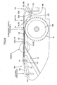
FIG. 4 is a side view showing an attached state of a component supply unit. -
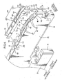
FIG. 5 is a perspective view of a front portion of the component supply unit (which shows a state after a guide device is detached therefrom). -
FIG. 6 is a perspective view of the front portion of the component supply unit (which shows a state before a cover tape is peeled off). -
FIG. 7 is a perspective view of the front portion of the component supply unit (which shows a state after the cover tape is set to a turnaround portion). -
FIG. 8 is a side view of the front portion of the component supply unit (which shows a state after a rear end of a tape guide is lifted). -
FIG. 9 is a side view of the front portion of the component supply unit (which shows a state after the component supply tape is pulled out from a front end of the unit). -
FIG. 10 is a side view of the front portion of the component supply unit (which shows a state when the cover tape is turned rearwardly through the turnaround portion). -
FIG. 11 is a sectional view taken along the line XI-XI inFIG. 7 . -
FIG. 12 is a sectional view taken along the line XII-XII inFIG. 7 . -
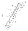
FIG. 13 is a perspective view of a tape guide used in a second embodiment. -
FIG. 14 is a perspective view of a tape guide used in a third embodiment. -
FIG. 15 is a diagram showing another embodiment. - A first embodiment of the present invention will be described with reference to
FIGS. 1 to 12 . - As shown in
FIGS. 1 and2 , asurface mounter 10 comprises aconveyer 20 for conveying a printed circuit board P, acomponent supply zone 30 disposed on each of opposite lateral sides of theconveyer 20, and ahead unit 25. - The
component supply zone 30 is formed by positioning a plurality ofcomponent supply units 40 in a side-by-side arrangement, on a carriage Ds which is mounted to a body of thesurface mounter 10 while being positioned in X, Y and Z directions. - The
head unit 25 takes on a function of picking up a component from thecomponent supply zone 30 and transferring the component onto the board P, wherein it is adapted to be movable in a region ranging from thecomponent supply zone 30 to a mounting position on the board P, under driving of a drive mechanism using a servomotor or the like. - The
head unit 25 includes a plurality ofheads 26 each of which has a distal end provided with a suction nozzle for suction-holding a component and attaching the component to the printed circuit board P. Each of the nozzles is designed to receive a supply of a negative pressure from negative-pressure generating means (not shown) during a component suction-pickup operation, and pick up a component by a suction force based on the negative pressure. - The
reference numeral 12 inFIG. 2 indicates a camera. Thecameral 12 takes on a function of imaging a component suction-held by thehead 26 to check whether a posture of the suction-held component is adequate. - In the
surface mounter 10 configured as above, thehead unit 25 is firstly moved to a position above an end of thecomponent supply zone 30 on the side of theconveyer 20 to pick up components from thecomponent supply unit 40. Then, after completion of the component pickup operation by thehead 26, the presence or absence of misalignment in component pickup position is checked by thecamera 12. Then, the picked-up components are transferred by thehead unit 25. During the transfer operation, the misalignment in component pickup position is corrected with respect to each of theheads 26. Then, when thehead 26 reaches a given component-attaching position, it is moved up and down, and the component is mounted onto the printed circuit board P according to the up-and-down movement. - The
component supply unit 40 is primarily made up of a feed-outdevice 51, aguide device 100, a take-indevice 61, and aunit body 41 to which these devices are fixed, and designed to feed out an after-mentionedcomponent supply tape 35 to supply components. Thecomponent supply tape 35 is fed out in a direction from a left side to a right side inFIG. 4 , along a longitudinal direction of thecomponent supply unit 40. In the following description, the longitudinal direction of thecomponent supply unit 50 will be referred to as "frontward-rearward direction", and the terms "front" and "rear" concerning thecomponent supply unit 40 will be used in accordance with a feed direction of thecomponent supply tape 35. That is, inFIG. 4 , the right side (side closer to the conveyer 20) is a front side, and the left side is a rear side. - The
component supply tape 35 has a structure as shown in FIG. 3A, which comprises acarrier tape 36, and acover tape 37 attached to thecarrier tape 36. Thecarrier tape 36 has a plurality of cavity-likecomponent storage portions 36a opened upwardly and arranged at constant intervals, and a component, such as IC, is stored in each of thecomponent storage portions 36a. Further, thecarrier tape 36 has a plurality ofengagement holes 36 provided in one of opposite edge regions along an edge thereof at constant intervals. Thecomponent supply tape 35 is wound and supported by a reel (not shown) at a rearward position of thecomponent supply unit 40. - As shown in
FIG. 4 , theunit body 41 of thecomponent supply unit 40 has a shape elongated in the frontward-rearward direction, and ahousing 75 is installed to a rear end of theunit body 41. Theunit body 41 and thehousing 75 are provided with a feed path B for allowing thecomponent supply tape 35 to travel therethrough. The feed path B extends frontwardly from a lower region of a rear end of thehousing 75 straight and horizontally and connects to theunit body 41. Then, the feed path B extends to a position above a front portion of theunit body 41 while taking a route directed obliquely frontwardly, and then extends frontwardly along an upper side of theunit body 41. In the following description, a portion of the feed path B extending in the frontward-rearward direction along the upper side of theunit body 41 will be referred to as "upper feed path Bu". - The feed-out
device 51 and theguide device 100 as will be described below are disposed on a frontward side of theunit body 41 with respect to the feed path B, and the take-indevice 61 is provided on the other side with respect to the feed path B. - The feed-out
device 51 takes on a function of allowing thecomponent supply tape 35 to be unreeled from a reel (not shown), and comprises afirst motor 52, agear 53, agear 54, agear 55A, and asprocket 55 integrated with thegear 55A. Thesprocket 55 is disposed in an upper region of a front end of theunit body 41, and thegears first motor 52 are disposed below and rearward of thesprocket 55. - The
guide device 100 will be described below. Theguide device 100 comprises atape guide 110 to be attached above the upper feed path Bu illustrated inFIG. 5 , and afirst retainer section 150 and asecond retainer section 160 for supporting thetape guide 110. - The upper feed path Bu is formed along a top surface portion of a
base member 43 provided in an upper end of the front portion of theunit body 41 to extend in a longitudinal direction of thebase member 43. A portion of thebase member 43 ranging from a rear end to a center thereof is formed as aflat portion 44 where a tape feed surface extends approximately horizontal. In theguide device 100 in the first embodiment, a component supply position O is positioned at a position on the side of a front end of theflat portion 44, and the tape being fed along the upper feed path Bu has a horizontal posture before it reaches the component supply position O, and then reaches the component supply position O while keeping the horizontal posture. - A portion of the
base member 43 located frontward of theflat portion 44, i.e., frontward of the component supply position O, is formed as a downwardly-inclined portion 45 where the tape feed surface extends gently obliquely downwardly. A lateral edge portion of thebase member 43 ranging from a front region of theflat portion 44 and a rear region of the downwardly-inclined portion 45 is cut out, so that a teeth portion of thesprocket 55 is exposed from the cutout. This makes it possible to allow teeth of thesprocket 55 to be engaged with the engagement holes 36b of thecarrier tape 36 being fed on and along the upper feed portion Bu. - Further, a
seat portion 46 is formed frontward of the downwardly-inclined portion 45. Theseat portion 46 is formed to have a height position lower than that of the lowerinclined portion 45 in order to receive an after-mentionedbottom wall 121 of thetape guide 110. Further, thebase member 43 is provided with anescape groove 47 concaved along the longitudinal direction. Theescape groove 47 is designed to avoid interference with thecomponent storage portions 36a provided in thecomponent supply tape 35. - The
tape guide 110 will be described below. Thetape guide 110 is made of a synthetic resin, and formed to have a shape which is generally elongated in one direction along the upper feed path Bu. Thetape guide 110 is functionally divided into a front guide section 120 (which corresponds to "downstream guide section" in the appended claims), and a rear guide section 130 (which corresponds to "upstream guide section" in the appended claims). - The
rear guide section 130 is formed in a cross-sectionally angular C shape having an opening oriented downwardly. More specifically, therear guide section 130 has a shape where respective upper edges of a pair ofsidewalls 112, 114 (which correspond to "pair of guide walls" in the appended claims) thereof are connected to each other by aceiling wall 131. Therear guide section 130 is designed to guide thecomponent supply tape 35 in a region upstream of the component supply position O in a tape feed direction to keep thecomponent supply tape 35 in a normal posture. - Specifically, as shown in
FIG. 11 , theflat portion 44 of thebase member 43 has opposite shoulders each formed as a mountingseat 44A having a width equal to that of a corresponding one of thesidewalls rear guide section 130. Further, therear guide section 130 is formed such that a width between respective wall surfaces of the right and leftsidewalls flat portion 44 of thebase member 43, whereby, during an attaching operation (seeFIG. 11 ), each of thesidewalls rear guide section 130 is fitted on the respective mountingseats 44A without a gap therebetween. - Thus, in the fitted state, the
sidewalls rear guide section 130 are gaplessly located on both sides of the upper feed path Bu formed in the top surface portion of thebase member 43, to restrain a widthwise displacement of thecomponent supply tape 35. In the first embodiment, thecomponent supply tape 35 has a width set to be approximately equal to that of theflat portion 44 of thebase member 43. - As shown in
FIG. 5 , thetape guide 110 is further formed with a component-pressingportion 136 at a position frontward of theceiling wall 131 of therear guide section 130. The component-pressingportion 136 is divided from theceiling wall 131 by aslit 135. Theslit 135 has an L shape which has one side extending in a widthwise direction of thetape guide 110 and the other side extending in a longitudinal direction of thetape guide 110. Theceiling wall 131 has a front edge serving as aturnaround portion 137. - The
turnaround portion 137 takes on a function of allowing thecover tape 37 to be turned in the rearward direction of the unit, and the component-pressingportion 136 is designed to cover a top surface of thecomponent storage portion 36a of thecarrier tape 36 during a course after thecover tape 37 is peeled off therefrom, through until thecomponent storage portion 36a reaches the component supply position O, so as to restrain jump-out of a component. - The
tape guide 110 further has alock pin 141 provided at a position on the side of a rear end of therear guide section 130 to bridge between the right and leftsidewalls lock pin 141 is adapted to be detachably retained by thesecond retainer section 160 as will be described later. - The
front guide section 120 will be described below. Thefront guide section 120 is formed in a cross-sectionally angular C shape having an open ceiling. More specifically, thefront guide section 120 has a shape where respective lower edges of right and leftsidewalls bottom wall 121. - A lower portion of the
front guide section 120, i.e., thebottom wall 121, is formed in a shape corresponding to that of theseat portion 46, i.e., inclined slightly obliquely downwardly. Further, thefront guide section 120 has a font end formed as anengagement portion 123. Theengagement portion 123 is formed to protrude frontwardly, and adapted to be locked by after-mentionedlock pieces first retainer section 150. - The
front guide section 120 is designed to guide thecomponent supply tape 35 in a region downstream of the component supply position O in the tape feed direction to keep thecomponent supply tape 35 in the normal posture. Specifically, during a tape feed operation, thecarrier tape 36 travels along an upper surface of thebottom wall 121, as shown inFIG. 12 . Further, thesidewalls front guide section 120 are located on respective ones of widthwisely opposite sides of thecarrier tape 36 to guide thecomponent supply tape 35. - As shown in
FIG. 5 , thefront guide section 120 has an opening formed in a top surface thereof to extend from the component-pressingportion 136 to a front end of thetape guide portion 110. This opening serves as anopen surface 128 which is formed to continuously extend to a front opening provided in the front end of thetape guide 110 and have an approximately even width over the overall length thereof. - In this manner, the
front guide section 120 is formed to have theopen surface 128 opened on the side of the top surface thereof in a continuous manner in the tape feed direction (frontward-rearward direction). This makes it possible to perform a setting operation for the cover tape 37 (details of the setting operation will be described later) in a simple and easy manner. In the first embodiment, a rear end of theopen surface 128 is communicated with theturnaround portion 137 through theslit 135. - As shown in
FIGS. 5 and12 , an upper edge of each of the right and leftsidewalls front guide section 120 is bent inwardly. This bent portion serves as a jump-outrestraint wall 125 which takes on a function of restraining jump-out of the component supply tape 35 (carrier tape 36) traveling through thefront guide section 120. - Although the
front guide section 120 and therear guide section 130 have been described separately, therespective sidewalls rear guide sections rear guide sections - Each of the
sidewalls tape guide 110 has a shape in side view as shown inFIGS. 5 and6 , which is conformable to an upper edge of theunit body 41. A portion of theunit body 41 providing a mating surface with thetape guide 110 has a rear region formed in a flat shape, and a front region (corresponding to the sprocket 55) formed to protrude in an arc shape. Thus, in conformity to the shape of theunit body 41, a lower edge of each of thesidewalls tape guide 110 has a rear region formed in a flat shape, and a front region cut out in an arc shape. In the following description, the protruding portion of theunit body 41, and the portion of thetape guide 110 corresponding to the protruding portion, will be referred to as "protrudingportion 48" and "arc-shapedcutout portion 112A", respectively. - The
first retainer section 150 will be described below. Thefirst retainer section 150 is attached to the front end of theunit body 41 through a hinge C1, and biased in a locking direction (direction indicated by H inFIG. 5 ) by biasing means (not shown). Thefirst retainer section 150 has atape discharge passage 151 provided in an upper portion thereof, and a pair oflock pieces tape discharge passage 151. Thelock pieces engagement portion 123 provided at the front end of thetape guide 110. - In the
lock pieces lock piece 153 on a near side inFIG. 5 extends obliquely toward theseat portion 46 of theunit body 41. More specifically, thelock piece 153 extends obliquely while assuring a gap for receiving theengagement portion 123 therein, with respect to theseat portion 46. On the other hand, the lock piece on a back side juts upwardly while extending obliquely toward theseat portion 46. This upwardly-jutting portion is used as amanual operation portion 156. - The
second retainer section 160 will be described below. Thesecond retainer section 160 is provided rearward of thebase member 43, and formed with alock groove 161 having an axis extending in a widthwise direction of thecomponent supply unit 40. Thelock groove 161 is adapted to allow thelock pin 141 of thetape guide 110 to be inserted thereinto so as to retain thelock pin 141, and formed to be opened upwardly. - Further, the
second retainer section 160 has apressing piece 165 attached at a position thereof rearward of thelock groove 161. Thepressing piece 165 is formed in a shape extending in the frontward-rearward direction of thecomponent supply unit 40, and swingably attached through a hinge C2. Thepressing piece 165 has alock spring 167 provided at a rear end thereof to bias thepressing piece 165 in a locking direction (direction indicated by H inFIG. 5 ). - Thus, after the
tape guide 110 is placed on thebase member 43, front and rear portions of thetape guide 110 are locked by the first andsecond retainer sections tape guide 110 is retained above the upper feed path Bu. Specifically, in the front portion of thetape guide 110, thelock pieces first retainer section 150 come into engagement with theengagement portion 123 at the front end of thetape guide 110 to lock the front portion of thetape guide 110. Further, in the rear portion of thetape guide 110, thepressing piece 165 presses thelock pin 141 toward a bottom of thelock groove 161 to lock the rear portion of thetape guide 110. - An attached state of the
tape guide 110 is shown inFIG. 9 . In the attached state, theceiling wall 131 of thetape guide 110 has a posture parallel to theflat portion 44 of thebase member 43. The reason is as follows. When thelock pin 141 is pressed toward the bottom of thelock groove 161, thetape guide 110 is apt to be swingably moved, for example, about a vertex of the protruding portion 48 (FIG. 5 ), to cause lift of the front end thereof. However, theengagement portion 123 located in the front end is brought into contact withlower edges lock pieces tape guide 110 is restricted. Accordingly, theceiling wall 131 of thetable guide 110 is set in a horizontal posture. - In this manner, the
ceiling wall 131 of thetable guide 110 is kept in a horizontal posture, so that thecomponent supply tape 35 in the course of feeding is pressed from thereabove and therebelow by theceiling wall 131 of thetable guide 110 and theflat portion 44 of thebase member 43. This makes it possible to effectively restrain uplift and inclination of the tape during feeding. - In an operation of releasing the retention of the front end of the
tape guide 110 by thefirst retainer section 150, themanual operation portion 156 may be manually pushed in the frontward direction of the unit, so that an entirety of thefirst retainer section 150 is tilted in the frontward direction of the unit to release the locked state. In an operation of releasing the retention of the rear end of thetape guide 110 by thesecond retainer section 160, the rear end of thepressing piece 165 may be pushed downwardly, so that restraint of thelock pin 141 is released, and consequently the locked state of the rear end of thetape guide 110 is released. - Returning to
FIG. 4 , the take-indevice 61 will be described below. The take-indevice 61 takes on a function of peeling off thecover tape 37 from thecarrier tape 36 along with the feed-out of thecomponent supply tape 35, to expose the components, and a function of taking in the peeledtape 37, and comprises asecond motor 62, agear 63, agear 64A, a take-inroller 64 integrated with thegear 64A, and apinch roller 65. - The
pinch roller 65 and the take-inroller 64 are in close contact with each other, so that, in response to activation of thesecond motor 62, a force in a pulling direction is applied to thecover tape 37 turned in the rearward direction of the unit by theturnaround portion 137, based on a frictional force between therollers - Further, a
control board 78 of thecomponent supply unit 40 is housed in abox 77 and disposed at a position below and on the side of the rear end of theunit body 41. Aconnector 79 is installed to a front end of thebox 77. When thecomponent supply unit 40 is attached to the carriage Ds, the connector at the end of thebox 77 is electrically connected to a counterpart connector, so that electric power and various control signals are input from thesurface mounter 10 through the carriage Ds. Thecontrol board 78 is designed to control/govern an entirety of thecomponent supply unit 40, in cooperation with a control unit (not shown) of thesurface mounter 10. - In the above
component supply unit 40, the components are supplied in the following manner. - Upon activation of the
first motor 52, a driving force of thefirst motor 52 is transmitted to thesprocket 55 via thegear 53, thegear 54 and thegear 55A, and thesprocket 55 starts rotating. - Thus, the
component supply tape 35 is unreeled from the reel (not shown). Thecomponent supply tape 35 travels toward the front portion of thecomponent supply unit 40 through the feed path B, and eventually reaches the upper feed path Bu. - When the
component supply tape 35 after reaching the upper feed path Bu passes through theturnaround portion 137, thecover tape 37 is peeled off by the take-indevice 61. Subsequently, only thecarrier tape 36 is fed through the upper feed path Bu toward the component supply position O. - A portion of the
carrier tape 36 subjected to the cover-tape peeling operation is fed under a condition that an upper side of each of thecomponent storage portions 36a is covered by the component-pressingportion 136 of thetape guide 110, and then the component within thecomponent storage portion 36a is exposed after passing through the component-pressingportion 136. - Subsequently, the
component storage portion 36a of thecarrier tape 36 reaches the component supply position O. In the component supply position O, the exposed component is picked up by thehead 26 of thesurface mounter 10. Then, the portion of thecarrier tape 36 subjected to the component pickup operation is discharged outside the unit through the downwardly-inclined portion 45, thebottom wall 121 of thetape guide 110, and thetape discharge passage 151 of thefirst retainer section 150. Concurrently, the peeledcover tape 37 is taken in in the rearward direction of the unit by the take-indevice 61, and received in an internal space of thehousing 75. - Once the component supply operation is initiated, the
component supply tape 35 is unreeled at constant intervals in the aforementioned manner, so that the components are sequentially fed to the component supply position O. - A tape setting operation will be described below which is to be performed when the reel (not shown) having the
component supply tape 35 wound therearound is replaced. - When the reel is replaced, the
component supply tape 35 has to be set to theunit body 41 of thecomponent supply unit 40. In this operation, thecomponent supply tape 35 is pulled out from the reel (not shown) by a certain length. Then, thecomponent supply tape 35 is manually inserted into the feed path B from the rear end of thehousing 75. - After the
component supply tape 35 is inserted into the feed path B to some extent, the rear end of thepressing piece 165 of thesecond retainer section 160 is then pushed downwardly to allow the pressed state of thelock pin 141 by the front end of thepressing piece 165 to be released, as shown inFIG. 8 . Through this operation, the restraint of the rear end of thetape guide 110 is released, and thereby thetape guide 110 has an inclined posture in which the rear end of thetape guide 110 is slightly lifted, so that a gap for allowing thecomponent supply tape 35 to be inserted into the upper feed path Bu is created between theflat portion 44 of thebase member 43 and theceiling wall 131 of thetape guide 110. - After creating the gap through the above operation, a leading edge of the
component supply tape 35 is manually fed out in the frontward direction of the unit, via therear guide section 130, thefront guide section 120 and thetape discharge passage 151 in this order, so as to allow thecomponent supply tape 35 to be pulled out from a front end of thecomponent supply unit 40 to an outside of the component supply unit 40 (seeFIGS. 6 and9 ). - After completion of the pull-out operation for the
component supply tape 35, a leading edge of thecover tape 37 is then manually pulled to peel off thecover tape 37 from thecarrier tape 36 by a given length. Subsequently, the leading edge of the peeledcover tape 37 is manually pinched and pulled in the rearward direction of the unit along theopen surface 128. - Through this operation, only the
cover tape 37 can be pulled back in the rearward direction of the unit along theopen surface 128 while leaving thecarrier tape 36 within thefront guide section 120. Subsequently, the pulled-back cover tape 37 is set to the turnaround portion 132 through the slit 135 (FIGS. 7 and10 ). In advance of this operation, thepressing piece 165 of thesecond retainer section 160 may be pushed in the release direction to set the rear end of thetape guide 110 in a slightly lifted posture, in the same manner as that in the operation of inserting thecomponent supply tape 35 into the upper feed path. This makes it possible to more smoothly perform the operation of setting thecover tape 37 to the turnaround portion 132 (an operation of inserting thecover tape 37 into the slit 135). - After the
cover tape 37 is set to theturnaround portion 137 in the above manner, thecover tape 37 is arranged to allow the leading edge thereof to be held between the tworollers device 61, and thecarrier tape 36 is arranged to allow theengagement holes 36a thereof to be engaged with the teeth of thesprocket 55. Now, the tape setting operation is completed to achieve a state allowing for component supply. - In the first embodiment, the
front guide section 120 is provided with theopen surface 128 opened on the side of the top surface thereof in a continuous manner in the tape feed direction, whereby thecover tape 37 can be freely taken in and out relative to thefront guide section 120 through theopen surface 128. In this configuration, under the condition that thetape guide 110 remains fixed above the upper feed path Bu, the setting operation for thecover tape 37 can be performed through the aforementioned given operational steps. This makes it possible to perform the setting operation for thecover tape 37, in a simple and efficient manner. - The
open surface 128 is formed in thefront guide section 120 in the above manner. Thus, even if the component drops onto the upper feed path Bu due to the occurrence of pickup miss during the component supply operation, the dropped component is effectively kept from lodging inside thefront guide section 120. Further, theopen surface 128 is opened upwardly. Thus, even if the lodging of the component occurs, the lodged component can be readily removed through the upwardly-openedopen surface 128. - In an ordinary approach, the strength of the
front guide section 120 is ensured by connecting the right and leftsidewalls open surface 128. Although this may raise concern about deterioration in the strength, the same level of stiffness as that of a structure devoid of theopen surface 128 can be ensured, because, in the first embodiment, thebottom wall 121 is provided to connect respective lower portions of thesidewalls - In the first embodiment, the
rear guide section 130 is further provided upstream of the component supply position O, wherein therear guide section 130 and thefront guide section 120 are adapted to guide thecomponent supply tape 35 on opposite rearward and frontward sides of the component supply position O. This configuration makes it possible to more reliably guide the tape as compared with a case where thecomponent supply tape 35 is guided on only one of the rearward and frontward sides. - In the first embodiment, the
ceiling wall 131 is provided in therear guide section 130, wherein the front edge of theceiling wall 137 is formed as theturnaround portion 137, and the component-pressingportion 136 is provided frontward of theturnaround portion 137 and adapted to press an upper surface of the component supply tape 35 (carrier tape 36) in the state after thecover tape 37 is peeled off therefrom. This configuration makes it possible to allow thecover tape 37 to be turned in direction in a simple and rational structure, and restrain jump-out of the components from thecarrier tape 36. - Further, the
front guide section 120 and therear guide section 130 are integrally formed. This configuration makes it possible to reduce the number of structural members, which provides superiority in regard to cost. - Furthermore, the
tape guide 110 is configured such that the front end thereof is lockable by thefirst retainer section 150, and the rear end thereof is lockable by thesecond retainer section 160. A locked state in each of the ends can be released by a simple manual operation, to facilitate detaching and replacing thetape guide 110. - A second embodiment of the present invention will be described below.
- The
tape guide 110 in the first embodiment is provided with the component-pressingportion 136, whereas the component-pressingportion 136 is eliminated in the second embodiment. Specifically, atape guide 200 in the second embodiment has a shape as shown inFIG. 13 , wherein the remaining portion other than the component-pressingportion 136 has the same shape as that in the first embodiment. - The component-pressing
portion 136 is intended to restrain jump-out of the components after the tape peeling operation. Thus, in cases where there is no risk of jump-out of the components after the peeling operation, it is not essential to provide the component-pressingportion 136, but it may be rather advantageous to avoid setup of the component-pressing portion 136 (e.g., in case where a process of removing static charges is performed after the peeling operation). - Thus, both the
tape guide 110 in the first embodiment and thetape guide 200 in the second embodiment may be prepared. In this case, either one of the tape guides 110, 200 can be selectively used depending on the situation. - In the above case, when the tape guide 200 (110) is retained relative to the upper end of the front portion of the unit body 41 (retained above the upper feed path Bu) under the condition that it is locked by the
first retainer section 150 and thesecond retainer section 160, the tape guide 200 (110) can be readily detached from theunit body 41 by releasing the locked state thereof. Then, when the tape guide 200 (110) is attached to theunit body 41, the tape guide 200 (110) can be readily fixed to theunit body 41 by simply retaining front and rear ends of the tape guide 200 (110) using thefirst retainer section 150 and thesecond retainer section 160. In this manner, the replacement operation can be performed relatively easily. This is also advantageous. - A third embodiment of the present invention will be described below.
- The
tape guide 110 in the first embodiment is made of a resin material, whereas a tape guide in the third embodiment is a reinforced type thereof. The tape guide in the third embodiment has a shape as shown inFIG. 14 , wherein ametal reinforcing plate 220 is laminated on each of right and leftsidewalls 215 of a resin tape-guide body 210 by a bonding process or an integral molding process. - The present invention is not limited to the above embodiments described and illustrated in the figures. For example, the following embodiments are also includes in the technical scope of the present invention, and various changes and modifications may further be made therein without departing from the scope of the present invention.
-
- (1) Although the first to third embodiments have been described based on one example where the
component supply unit 40 is an electrically-driven type using a motor as a driving source, the component supply unit in the present invention is not limited to this type. For example, the present invention may be applied to a ratchet type. -
- (2) Although, in the first to third embodiments, a ceiling wall of the
front guide section 120 is omitted to form theopen surface 128 opened on the top surface of thefront guide section 120, a position for forming theopen surface 128 is not limited to the top surface of thefront guide section 120. For example, the open surface may be provided in any suitable position having no negative effect on a guide function, e.g., in thesidewalls -
- (3) Although the first to third embodiments have been described based on one example where the
front guide section 120 and therear guide section 130 are integrally formed, it is not essential to form the twoguide sections FIG. 15 , thefront guide section 120 and therear guide section 130 may be formed as separate members. - In this case, the
front guide section 120 may be directly fixed to theseat portion 46 of theunit body 41 using a fastener, such as a screw. Alternatively, thefront guide section 120 may be integrally formed with theunit body 41. This makes it possible to effectively prevent an increase in the number of structural members. - On the other hand, the
rear guide section 130 is preferably fixed in such a manner that a rear end thereof is pivotally supported by theunit body 41 through a lock pin 141 (which corresponds to "pin member" in the appended claims), and afront end 138 thereof is locked relative to theunit body 41 through a locking device (capable of locking the front end and releasing the locked state thereof according to given manual operations) (not shown). In this configuration, when the locked state of thefront end 138 is released, therear guide section 130 can be manually opened upwardly to facilitate the operation of inserting thecomponent supply tape 35 into the upper feed path Bu. - (4) If there is an appropriate gap between the
tape guide 110 and thebase member 43 when thecomponent supply tape 35 is replaced, the operation of inserting thecomponent supply tape 35 into the upper feed path Bu can be facilitated to provide enhanced operational efficiency. In regard to this point, although the component supply unit in the first embodiment is configured such that the retention of the rear end of thetape guide 110 is released to lift the rear end so as to create a gap (indicated in the area G inFIG. 8 ) between thetape guide 110 and the upper feed path Bu, a position for releasing the retention of thetape guide 110 is not limited to the rear end, but the retention of the front end may be released. - Specifically, the component supply unit in the first embodiment is configured such that the front end of the
tape guide 110 is retained by thefirst retainer section 150. Thus, the locked state of the front end by thefirst retainer section 150 can be readily released by pushing themanual operation portion 156 in the frontward direction of the unit. Then, the front end of thetape guide 110 can be lifted to ensure an appropriate,gap between thetape guide 110 and thebase member 43 in the same manner as that in the first embodiment, so as to allow thecomponent supply tape 35 to be inserted into the upper feed path Bu without difficulty. After thecomponent supply tape 35 is inserted into the upper feed path Bu, thetape guide 110 can be readily fixed by returning thefirst retainer section 150 to its original upstanding posture (the posture illustrated inFIG. 8 ). - In the last place, elements of the present invention disclosed based on the above embodiments and advantages thereof will be described in a summarized manner.
- The present invention provides a component supply unit, which comprises: a feed-out device adapted to intermittently feed out a component supply tape toward a component supply position provided on a feed path extending in a given direction, wherein the component supply tape includes a carrier tape having components stored therein at constant intervals, and a cover tape attached to the carrier tape to prevent jump-out of the stored components; a guide device set up along the feed path and adapted to guide the component supply tape from widthwisely opposite sides thereof to keep a feed posture of the component supply tape in a normal posture; a turnaround portion set up above the feed path; and a take-in device adapted to take in the cover tape turned through the turnaround portion to peel off the cover tape from the carrier tape, during a course of feeding the component supply tape, wherein the guide device includes a downstream guide section located downstream of the component supply position in a tape feed direction and adapted to guide the component supply tape, and wherein the downstream guide section is provided with an open surface opened on one side thereof in a continuous manner in the tape feed direction, whereby the cover tape can be taken in and out relative to the downstream guide section through the open surface.
- In the present invention, the downstream guide section is provided with an open surface opened on one side thereof in a continuous manner in the tape feed direction, whereby the cover tape can be taken in and out relative to the downstream guide section through the open surface. This configuration makes it possible to perform a cover tape setting operation through given operational steps, under a condition that the downstream guide section remains fixed to the component supply unit, so as to save time and effort for the operation.
- The following configurations are preferable as an embodiment of the present invention.
- When the downstream guide section has a pair of guide walls located on the widthwisely opposite sides of the component supply tape, the open surface is formed in a top surface between the pair of guide walls. The open surface opened upwardly provides enhanced operational efficiency.
- The downstream guide section is configured to have a bottom wall connecting respective lower portions of the pair of guide walls. This configuration makes it possible to ensure proper strength.
- The downstream guide section is integrally provided in a unit body of the component supply unit. This configuration makes it possible to reduce the number of structural members.
- The component supply unit includes an upstream guide section located upstream of the component supply position in the tape feed direction and adapted to guide the component supply tape, wherein the upstream guide section and the downstream guide section are adapted to guide the component supply tape on opposite rearward and frontward sides of the component supply position. This configuration makes it possible to more reliably guide the component supply tape to keep the component supply tape in the normal posture.
- When the upstream guide section has a pair of guide walls adapted to guide the component supply tape from the widthwisely opposite sides thereof, the upstream guide section is configured to have a ceiling wall connecting respective upper portions of the guide walls, wherein a front edge of the ceiling wall serves as the turnaround portion.
- Further, the upstream guide section is configured to have a component-pressing portion provided frontward of the turnaround portion and adapted to press an upper surface of the component supply tape in a state after the cover tape is peeled off therefrom. These configurations make it possible to allow the cover tape to be turned in direction, and restrain jump-out of the components from the carrier tape, in a simple and rational structure.
- The upstream guide section has, in a longitudinal direction thereof, one end pivotally supported by the unit body of the component supply unit through a pin member, and the other end locked relative to the unit body through a locking device, wherein the upstream guide section is adapted to be manually opened upwardly about the pin member after releasing a locked state thereof by the locking device. This configuration makes it possible to facilitate a setting operation for the component supply tape.
- The upstream guide section and the downstream guide section are integrally formed. This configuration makes it possible to reduce the number of structural members, which is advantageous in regard to management and cost thereof. In addition, the integrated member is increased in stiffness so as to more reliably guide the tape.
Claims (10)
- A component supply unit comprising:a feed-out device adapted to intermittently feed out a component supply tape toward a component supply position provided on a feed path extending in a given direction, the component supply tape including a carrier tape having components stored therein at constant intervals, and a cover tape attached to the carrier tape to prevent jump-out of the stored components;a guide device set up along the feed path and adapted to guide the component supply tape from widthwisely opposite sides thereof to keep a feed posture of the component supply tape in a normal posture;a turnaround portion set up above the feed path; anda take-in device adapted to take in the cover tape turned through the turnaround portion to peel off the cover tape from the carrier tape, during a course of feeding the component supply tape,wherein the guide device includes a downstream guide section located downstream of the component supply position in a tape feed direction and adapted to guide the component supply tape, the downstream guide section being provided with an open surface opened on one side thereof in a continuous manner in the tape feed direction, whereby the cover tape can be taken in and out relative to the downstream guide section through the open surface.
- The component supply unit as defined in claim 1, wherein the downstream guide section has a pair of guide walls located on the widthwisely opposite sides of the component supply tape, and the open surface is formed in a top surface between the pair of guide walls.
- The component supply unit as defined in claim 2, wherein the downstream guide section has a bottom wall connecting respective lower portions of the pair of guide walls.
- The component supply unit as defined in any one of claims 1 to 3, wherein the downstream guide section is integrally provided in a unit body of the component supply unit.
- The component supply unit as defined in any one of claims 1 to 4, which includes an upstream guide section located upstream of the component supply position in the tape feed direction and adapted to guide the component supply tape, wherein the upstream guide section and the downstream guide section are adapted to guide the component supply tape on opposite rearward and frontward sides of the component supply position.
- The component supply unit as defined in claim 5, wherein the upstream guide section has a pair of guide walls adapted to guide the component supply tape from the widthwisely opposite sides thereof, and a ceiling wall connecting respective upper portions of the guide walls, wherein a front edge of the ceiling wall serves as the turnaround portion.
- The component supply unit as defined in claim 6, wherein the upstream guide section has a component-pressing portion provided frontward of the turnaround portion and adapted to press an upper surface of the component supply tape in a state after the cover tape is peeled off therefrom.
- The component supply unit as defined in any one of claims 5 to 7, wherein the upstream guide section has, in a longitudinal direction thereof, one end pivotally supported by the unit body of the component supply unit through a pin member, and the other end locked relative to the unit body through a locking device, wherein the upstream guide section is adapted to be manually opened upwardly about the pin member after releasing a locked state thereof by the locking device.
- The component supply unit as defined in any one of claims 5 to 7, wherein the upstream guide section and the downstream guide section are integrally formed.
- A surface mounter adapted to receive a supply of the components from the component supply unit as defined in any one of claims 1 to 9, and mount the components on a board.
Applications Claiming Priority (2)
| Application Number | Priority Date | Filing Date | Title |
|---|---|---|---|
| JP2006271653A JP4820728B2 (en) | 2006-10-03 | 2006-10-03 | Component supply device and surface mounter |
| PCT/JP2007/069377 WO2008041725A1 (en) | 2006-10-03 | 2007-10-03 | Part feeder, and surface mounting machine |
Publications (3)
| Publication Number | Publication Date |
|---|---|
| EP2079294A1 true EP2079294A1 (en) | 2009-07-15 |
| EP2079294A4 EP2079294A4 (en) | 2010-07-28 |
| EP2079294B1 EP2079294B1 (en) | 2014-04-16 |
Family
ID=39268579
Family Applications (1)
| Application Number | Title | Priority Date | Filing Date |
|---|---|---|---|
| EP07829116.8A Active EP2079294B1 (en) | 2006-10-03 | 2007-10-03 | Component supply unit and surface mounter |
Country Status (5)
| Country | Link |
|---|---|
| US (1) | US7930819B2 (en) |
| EP (1) | EP2079294B1 (en) |
| JP (1) | JP4820728B2 (en) |
| CN (1) | CN101554101B (en) |
| WO (1) | WO2008041725A1 (en) |
Cited By (1)
| Publication number | Priority date | Publication date | Assignee | Title |
|---|---|---|---|---|
| US9578793B2 (en) | 2012-07-27 | 2017-02-21 | Panasonic Intellectual Property Management Co., Ltd. | Component supplying apparatus and component supplying method |
Families Citing this family (39)
| Publication number | Priority date | Publication date | Assignee | Title |
|---|---|---|---|---|
| JP5136552B2 (en) * | 2007-06-13 | 2013-02-06 | 富士通株式会社 | How to remove electronic components from carrier tape |
| JP4714256B2 (en) * | 2008-11-05 | 2011-06-29 | ヤマハ発動機株式会社 | Parts supply device |
| KR101546431B1 (en) | 2009-01-05 | 2015-08-25 | 한화테크윈 주식회사 | Tape guide opening and closing structure of tape feeder |
| JP5544058B2 (en) * | 2009-08-24 | 2014-07-09 | Juki株式会社 | Electronic component feeder |
| JP5357743B2 (en) * | 2009-12-26 | 2013-12-04 | 富士機械製造株式会社 | Electronic circuit component supply device |
| JP2011228600A (en) * | 2010-04-23 | 2011-11-10 | Juki Corp | Electronic component supply device |
| JP5597050B2 (en) * | 2010-07-15 | 2014-10-01 | 富士機械製造株式会社 | Substrate stop position control method and apparatus, and substrate mounting position control method |
| CN102638964B (en) * | 2011-02-08 | 2016-12-14 | 富士机械制造株式会社 | Multi-layered type swiveling head, component fitting machine and their using method |
| WO2013132599A1 (en) * | 2012-03-06 | 2013-09-12 | 富士機械製造株式会社 | Automated tape setting apparatus |
| EP3557965A1 (en) * | 2012-03-12 | 2019-10-23 | Mycronic AB | Device for automatic storage of electronic components |
| KR102025369B1 (en) * | 2012-09-12 | 2019-09-25 | 한화정밀기계 주식회사 | Tape feeding apparatus and method for chip mounter |
| KR101804379B1 (en) * | 2012-09-04 | 2018-01-10 | 한화테크윈 주식회사 | Electric chip carrier tape feeding deive and electric chip carrier tape feeding method |
| CN102833994A (en) * | 2012-09-10 | 2012-12-19 | 程江河 | Feeding device for chip mounter |
| JP5684219B2 (en) | 2012-12-05 | 2015-03-11 | ヤマハ発動機株式会社 | Jam prevention mechanism when cutting tape |
| WO2014147799A1 (en) * | 2013-03-21 | 2014-09-25 | 富士機械製造株式会社 | Tape feeder |
| JP6245517B2 (en) * | 2013-06-14 | 2017-12-13 | パナソニックIpマネジメント株式会社 | Component supply apparatus and component supply method |
| US10052858B2 (en) * | 2014-03-12 | 2018-08-21 | Edo Segal | Interlocking object construction units |
| CN104192497A (en) * | 2014-08-27 | 2014-12-10 | 昆山元崧电子科技有限公司 | Feeder capable of stably feeding materials |
| JP6427762B2 (en) * | 2014-10-20 | 2018-11-28 | パナソニックIpマネジメント株式会社 | Tape feeder |
| WO2016143040A1 (en) * | 2015-03-09 | 2016-09-15 | 富士機械製造株式会社 | Feeder |
| WO2016194136A1 (en) * | 2015-06-02 | 2016-12-08 | 富士機械製造株式会社 | Component mounting device and suction position setting method |
| US10342168B2 (en) * | 2015-06-18 | 2019-07-02 | Fuji Corporation | Feeder |
| JP6492289B2 (en) * | 2015-10-14 | 2019-04-03 | パナソニックIpマネジメント株式会社 | Component supply device and component mounting device |
| JP6473893B2 (en) * | 2015-12-25 | 2019-02-27 | パナソニックIpマネジメント株式会社 | Tape feeder and tape connecting device |
| TWI640465B (en) * | 2016-02-04 | 2018-11-11 | 萬潤科技股份有限公司 | Electronic component packaging carrier tape guiding method and device |
| CN108781527B (en) * | 2016-03-30 | 2020-06-23 | 雅马哈发动机株式会社 | Component supply device |
| DE102016217761B3 (en) * | 2016-09-16 | 2018-02-01 | Asm Assembly Systems Gmbh & Co. Kg | Component scraper and belt feeding device |
| JP6735849B2 (en) * | 2016-12-16 | 2020-08-05 | 株式会社Fuji | Tape feeder |
| CN110999565B (en) * | 2017-08-01 | 2021-03-19 | 雅马哈发动机株式会社 | Component supply device and component assembly machine equipped with the same |
| JP6824416B2 (en) * | 2017-08-01 | 2021-02-03 | ヤマハ発動機株式会社 | Parts supply device and parts mounting machine equipped with this |
| EP3522685B1 (en) * | 2018-02-05 | 2021-12-08 | AT & S Austria Technologie & Systemtechnik Aktiengesellschaft | Metallic layer as carrier for component embedded in cavity of component carrier |
| CN110936120A (en) * | 2018-09-21 | 2020-03-31 | 富鼎电子科技(嘉善)有限公司 | Automatic part assembling device |
| JP6814953B2 (en) * | 2019-01-11 | 2021-01-20 | パナソニックIpマネジメント株式会社 | Tape feeder and component mounting device |
| CN110035645B (en) * | 2019-04-09 | 2024-02-13 | 广东岩田智慧机电有限公司 | A material guiding device |
| JP7382594B2 (en) * | 2019-08-27 | 2023-11-17 | パナソニックIpマネジメント株式会社 | parts supply device |
| JP7331584B2 (en) * | 2019-09-25 | 2023-08-23 | オムロン株式会社 | LINEAR MEMBER ARRANGEMENT DEVICE AND LINEAR MEMBER ARRANGEMENT METHOD |
| CN112658672A (en) * | 2019-10-16 | 2021-04-16 | 富鼎电子科技(嘉善)有限公司 | Automatic part assembling equipment |
| CN111115257B (en) * | 2019-12-27 | 2021-08-27 | 深圳蓝普科技有限公司 | Material conveying device and LED module maintenance system |
| JP7117614B2 (en) * | 2020-12-02 | 2022-08-15 | パナソニックIpマネジメント株式会社 | Tape feeder and component mounter |
Family Cites Families (13)
| Publication number | Priority date | Publication date | Assignee | Title |
|---|---|---|---|---|
| US4810154A (en) * | 1988-02-23 | 1989-03-07 | Molex Incorporated | Component feeder apparatus and method for vision-controlled robotic placement system |
| JPH07114319B2 (en) * | 1991-01-22 | 1995-12-06 | 松下電器産業株式会社 | Chip type electronic parts supply device |
| KR970001239Y1 (en) * | 1993-12-29 | 1997-02-21 | 대우중공업 주식회사 | Automatic supplying device for electronic component taped in reel |
| JPH1174689A (en) * | 1997-08-28 | 1999-03-16 | Yamaha Motor Co Ltd | Tape feeder |
| JP3648966B2 (en) * | 1998-02-06 | 2005-05-18 | 松下電器産業株式会社 | Tape feeder |
| DE69923599T2 (en) * | 1998-12-22 | 2006-03-23 | Mydata Automation Ab | METHOD FOR TRANSMITTING COMPONENT BELT INFORMATION TO A COMPONENT FITTING APPARATUS AND DEVICE THEREFOR |
| KR100646909B1 (en) * | 1998-12-22 | 2006-11-23 | 마이데이터 오토메이션 아베 | Tape Guide and Tape Magazine on Component Mounting Machine |
| US6162007A (en) * | 1999-01-14 | 2000-12-19 | Witte; Stefan | Apparatus for feeding electronic component tape |
| US6652706B1 (en) * | 2000-12-01 | 2003-11-25 | Delaware Capital Formation, Inc. | Tape feeder with improved cover tape disposition path and drive |
| JP2003158397A (en) * | 2001-11-26 | 2003-05-30 | Sanyo Electric Co Ltd | Electronic component mounting device |
| US7052564B2 (en) * | 2003-03-28 | 2006-05-30 | Delaware Capital Formation, Inc. | Component feeder having a high density cover tape reservoir |
| JP2006156514A (en) * | 2004-11-26 | 2006-06-15 | Hitachi High-Tech Instruments Co Ltd | Parts supply device |
| CN2770290Y (en) * | 2004-12-24 | 2006-04-05 | 鸿富锦精密工业(深圳)有限公司 | Envelope reading-out device |
-
2006
- 2006-10-03 JP JP2006271653A patent/JP4820728B2/en active Active
-
2007
- 2007-10-03 US US12/444,106 patent/US7930819B2/en active Active
- 2007-10-03 WO PCT/JP2007/069377 patent/WO2008041725A1/en not_active Ceased
- 2007-10-03 CN CN2007800372623A patent/CN101554101B/en active Active
- 2007-10-03 EP EP07829116.8A patent/EP2079294B1/en active Active
Cited By (1)
| Publication number | Priority date | Publication date | Assignee | Title |
|---|---|---|---|---|
| US9578793B2 (en) | 2012-07-27 | 2017-02-21 | Panasonic Intellectual Property Management Co., Ltd. | Component supplying apparatus and component supplying method |
Also Published As
| Publication number | Publication date |
|---|---|
| JP4820728B2 (en) | 2011-11-24 |
| CN101554101A (en) | 2009-10-07 |
| WO2008041725A1 (en) | 2008-04-10 |
| EP2079294A4 (en) | 2010-07-28 |
| US7930819B2 (en) | 2011-04-26 |
| CN101554101B (en) | 2011-05-04 |
| JP2008091672A (en) | 2008-04-17 |
| EP2079294B1 (en) | 2014-04-16 |
| US20090249615A1 (en) | 2009-10-08 |
Similar Documents
| Publication | Publication Date | Title |
|---|---|---|
| US7930819B2 (en) | Component supply unit and surface mounter | |
| US8220141B2 (en) | Component supply apparatus and surface mounter | |
| JP4891832B2 (en) | Component supply device and surface mounter | |
| JP4969584B2 (en) | Tape feeder and component holding tape setting method | |
| CN108370660A (en) | Tape feeder | |
| US11765876B2 (en) | Exchange device | |
| CN101518173A (en) | Component supplying apparatus and surface mounting apparatus | |
| JP6094835B2 (en) | Component supply apparatus and component supply method | |
| JP5650428B2 (en) | Electronic component feeder | |
| JP7137319B2 (en) | Electronic component feeder and electronic component mounter | |
| JP2012195400A (en) | Tape feeder and component mounting device | |
| EP3154325B1 (en) | Component supply device and surface mounter | |
| JP2010114178A (en) | Component supply device | |
| EP3809809B1 (en) | Exchange device | |
| EP3817538B1 (en) | Feeder | |
| KR101133789B1 (en) | Carrier tape guide of tape feeder for chip mounter | |
| JP2009290047A (en) | Component supply device, and surface mounting machine provided with the same | |
| JPH06239522A (en) | Tape feeder | |
| JP2010103273A (en) | Component supply device | |
| JP4302267B2 (en) | Tape feeder | |
| JP4800165B2 (en) | Component supply device and surface mounter | |
| WO2026105291A1 (en) | Tape guide and tape feeder | |
| JP2026020148A (en) | Supply device, component cassette, and transportation method | |
| JP2002158490A (en) | Device for taking out part from package tape | |
| KR20130088661A (en) | Carrier tape guide of tape feeder for chip mounter |
Legal Events
| Date | Code | Title | Description |
|---|---|---|---|
| PUAI | Public reference made under article 153(3) epc to a published international application that has entered the european phase |
Free format text: ORIGINAL CODE: 0009012 |
|
| 17P | Request for examination filed |
Effective date: 20090430 |
|
| AK | Designated contracting states |
Kind code of ref document: A1 Designated state(s): AT BE BG CH CY CZ DE DK EE ES FI FR GB GR HU IE IS IT LI LT LU LV MC MT NL PL PT RO SE SI SK TR |
|
| A4 | Supplementary search report drawn up and despatched |
Effective date: 20100624 |
|
| DAX | Request for extension of the european patent (deleted) | ||
| REG | Reference to a national code |
Ref country code: DE Ref legal event code: R079 Ref document number: 602007036160 Country of ref document: DE Free format text: PREVIOUS MAIN CLASS: H05K0013020000 Ipc: H05K0013040000 |
|
| GRAP | Despatch of communication of intention to grant a patent |
Free format text: ORIGINAL CODE: EPIDOSNIGR1 |
|
| RIC1 | Information provided on ipc code assigned before grant |
Ipc: H05K 13/04 20060101AFI20131118BHEP |
|
| INTG | Intention to grant announced |
Effective date: 20131211 |
|
| RIN1 | Information on inventor provided before grant (corrected) |
Inventor name: YONEMITSU, MASANORI Inventor name: ARAKI, OSAMU |
|
| GRAP | Despatch of communication of intention to grant a patent |
Free format text: ORIGINAL CODE: EPIDOSNIGR1 |
|
| GRAS | Grant fee paid |
Free format text: ORIGINAL CODE: EPIDOSNIGR3 |
|
| GRAA | (expected) grant |
Free format text: ORIGINAL CODE: 0009210 |
|
| INTG | Intention to grant announced |
Effective date: 20140218 |
|
| AK | Designated contracting states |
Kind code of ref document: B1 Designated state(s): AT BE BG CH CY CZ DE DK EE ES FI FR GB GR HU IE IS IT LI LT LU LV MC MT NL PL PT RO SE SI SK TR |
|
| REG | Reference to a national code |
Ref country code: GB Ref legal event code: FG4D |
|
| REG | Reference to a national code |
Ref country code: CH Ref legal event code: EP |
|
| REG | Reference to a national code |
Ref country code: AT Ref legal event code: REF Ref document number: 663200 Country of ref document: AT Kind code of ref document: T Effective date: 20140515 |
|
| REG | Reference to a national code |
Ref country code: IE Ref legal event code: FG4D |
|
| REG | Reference to a national code |
Ref country code: DE Ref legal event code: R096 Ref document number: 602007036160 Country of ref document: DE Effective date: 20140528 |
|
| REG | Reference to a national code |
Ref country code: AT Ref legal event code: MK05 Ref document number: 663200 Country of ref document: AT Kind code of ref document: T Effective date: 20140416 |
|
| REG | Reference to a national code |
Ref country code: NL Ref legal event code: VDEP Effective date: 20140416 |
|
| REG | Reference to a national code |
Ref country code: LT Ref legal event code: MG4D |
|
| PG25 | Lapsed in a contracting state [announced via postgrant information from national office to epo] |
Ref country code: BG Free format text: LAPSE BECAUSE OF FAILURE TO SUBMIT A TRANSLATION OF THE DESCRIPTION OR TO PAY THE FEE WITHIN THE PRESCRIBED TIME-LIMIT Effective date: 20140716 Ref country code: IS Free format text: LAPSE BECAUSE OF FAILURE TO SUBMIT A TRANSLATION OF THE DESCRIPTION OR TO PAY THE FEE WITHIN THE PRESCRIBED TIME-LIMIT Effective date: 20140816 Ref country code: FI Free format text: LAPSE BECAUSE OF FAILURE TO SUBMIT A TRANSLATION OF THE DESCRIPTION OR TO PAY THE FEE WITHIN THE PRESCRIBED TIME-LIMIT Effective date: 20140416 Ref country code: GR Free format text: LAPSE BECAUSE OF FAILURE TO SUBMIT A TRANSLATION OF THE DESCRIPTION OR TO PAY THE FEE WITHIN THE PRESCRIBED TIME-LIMIT Effective date: 20140717 Ref country code: CY Free format text: LAPSE BECAUSE OF FAILURE TO SUBMIT A TRANSLATION OF THE DESCRIPTION OR TO PAY THE FEE WITHIN THE PRESCRIBED TIME-LIMIT Effective date: 20140416 Ref country code: LT Free format text: LAPSE BECAUSE OF FAILURE TO SUBMIT A TRANSLATION OF THE DESCRIPTION OR TO PAY THE FEE WITHIN THE PRESCRIBED TIME-LIMIT Effective date: 20140416 Ref country code: NL Free format text: LAPSE BECAUSE OF FAILURE TO SUBMIT A TRANSLATION OF THE DESCRIPTION OR TO PAY THE FEE WITHIN THE PRESCRIBED TIME-LIMIT Effective date: 20140416 |
|
| PG25 | Lapsed in a contracting state [announced via postgrant information from national office to epo] |
Ref country code: LV Free format text: LAPSE BECAUSE OF FAILURE TO SUBMIT A TRANSLATION OF THE DESCRIPTION OR TO PAY THE FEE WITHIN THE PRESCRIBED TIME-LIMIT Effective date: 20140416 Ref country code: PL Free format text: LAPSE BECAUSE OF FAILURE TO SUBMIT A TRANSLATION OF THE DESCRIPTION OR TO PAY THE FEE WITHIN THE PRESCRIBED TIME-LIMIT Effective date: 20140416 Ref country code: AT Free format text: LAPSE BECAUSE OF FAILURE TO SUBMIT A TRANSLATION OF THE DESCRIPTION OR TO PAY THE FEE WITHIN THE PRESCRIBED TIME-LIMIT Effective date: 20140416 Ref country code: SE Free format text: LAPSE BECAUSE OF FAILURE TO SUBMIT A TRANSLATION OF THE DESCRIPTION OR TO PAY THE FEE WITHIN THE PRESCRIBED TIME-LIMIT Effective date: 20140416 Ref country code: ES Free format text: LAPSE BECAUSE OF FAILURE TO SUBMIT A TRANSLATION OF THE DESCRIPTION OR TO PAY THE FEE WITHIN THE PRESCRIBED TIME-LIMIT Effective date: 20140416 |
|
| PG25 | Lapsed in a contracting state [announced via postgrant information from national office to epo] |
Ref country code: PT Free format text: LAPSE BECAUSE OF FAILURE TO SUBMIT A TRANSLATION OF THE DESCRIPTION OR TO PAY THE FEE WITHIN THE PRESCRIBED TIME-LIMIT Effective date: 20140818 |
|
| REG | Reference to a national code |
Ref country code: DE Ref legal event code: R097 Ref document number: 602007036160 Country of ref document: DE |
|
| PG25 | Lapsed in a contracting state [announced via postgrant information from national office to epo] |
Ref country code: RO Free format text: LAPSE BECAUSE OF FAILURE TO SUBMIT A TRANSLATION OF THE DESCRIPTION OR TO PAY THE FEE WITHIN THE PRESCRIBED TIME-LIMIT Effective date: 20140416 Ref country code: EE Free format text: LAPSE BECAUSE OF FAILURE TO SUBMIT A TRANSLATION OF THE DESCRIPTION OR TO PAY THE FEE WITHIN THE PRESCRIBED TIME-LIMIT Effective date: 20140416 Ref country code: SK Free format text: LAPSE BECAUSE OF FAILURE TO SUBMIT A TRANSLATION OF THE DESCRIPTION OR TO PAY THE FEE WITHIN THE PRESCRIBED TIME-LIMIT Effective date: 20140416 Ref country code: BE Free format text: LAPSE BECAUSE OF FAILURE TO SUBMIT A TRANSLATION OF THE DESCRIPTION OR TO PAY THE FEE WITHIN THE PRESCRIBED TIME-LIMIT Effective date: 20140416 Ref country code: CZ Free format text: LAPSE BECAUSE OF FAILURE TO SUBMIT A TRANSLATION OF THE DESCRIPTION OR TO PAY THE FEE WITHIN THE PRESCRIBED TIME-LIMIT Effective date: 20140416 Ref country code: DK Free format text: LAPSE BECAUSE OF FAILURE TO SUBMIT A TRANSLATION OF THE DESCRIPTION OR TO PAY THE FEE WITHIN THE PRESCRIBED TIME-LIMIT Effective date: 20140416 |
|
| PLBE | No opposition filed within time limit |
Free format text: ORIGINAL CODE: 0009261 |
|
| STAA | Information on the status of an ep patent application or granted ep patent |
Free format text: STATUS: NO OPPOSITION FILED WITHIN TIME LIMIT |
|
| 26N | No opposition filed |
Effective date: 20150119 |
|
| PG25 | Lapsed in a contracting state [announced via postgrant information from national office to epo] |
Ref country code: IT Free format text: LAPSE BECAUSE OF FAILURE TO SUBMIT A TRANSLATION OF THE DESCRIPTION OR TO PAY THE FEE WITHIN THE PRESCRIBED TIME-LIMIT Effective date: 20140416 |
|
| REG | Reference to a national code |
Ref country code: DE Ref legal event code: R097 Ref document number: 602007036160 Country of ref document: DE Effective date: 20150119 |
|
| PG25 | Lapsed in a contracting state [announced via postgrant information from national office to epo] |
Ref country code: MC Free format text: LAPSE BECAUSE OF FAILURE TO SUBMIT A TRANSLATION OF THE DESCRIPTION OR TO PAY THE FEE WITHIN THE PRESCRIBED TIME-LIMIT Effective date: 20140416 Ref country code: LU Free format text: LAPSE BECAUSE OF FAILURE TO SUBMIT A TRANSLATION OF THE DESCRIPTION OR TO PAY THE FEE WITHIN THE PRESCRIBED TIME-LIMIT Effective date: 20141003 |
|
| REG | Reference to a national code |
Ref country code: CH Ref legal event code: PL |
|
| GBPC | Gb: european patent ceased through non-payment of renewal fee |
Effective date: 20141003 |
|
| REG | Reference to a national code |
Ref country code: IE Ref legal event code: MM4A |
|
| PG25 | Lapsed in a contracting state [announced via postgrant information from national office to epo] |
Ref country code: SI Free format text: LAPSE BECAUSE OF FAILURE TO SUBMIT A TRANSLATION OF THE DESCRIPTION OR TO PAY THE FEE WITHIN THE PRESCRIBED TIME-LIMIT Effective date: 20140416 Ref country code: CH Free format text: LAPSE BECAUSE OF NON-PAYMENT OF DUE FEES Effective date: 20141031 Ref country code: GB Free format text: LAPSE BECAUSE OF NON-PAYMENT OF DUE FEES Effective date: 20141003 Ref country code: LI Free format text: LAPSE BECAUSE OF NON-PAYMENT OF DUE FEES Effective date: 20141031 |
|
| REG | Reference to a national code |
Ref country code: FR Ref legal event code: ST Effective date: 20150630 |
|
| PG25 | Lapsed in a contracting state [announced via postgrant information from national office to epo] |
Ref country code: FR Free format text: LAPSE BECAUSE OF NON-PAYMENT OF DUE FEES Effective date: 20141031 |
|
| PG25 | Lapsed in a contracting state [announced via postgrant information from national office to epo] |
Ref country code: IE Free format text: LAPSE BECAUSE OF NON-PAYMENT OF DUE FEES Effective date: 20141003 |
|
| PG25 | Lapsed in a contracting state [announced via postgrant information from national office to epo] |
Ref country code: MT Free format text: LAPSE BECAUSE OF FAILURE TO SUBMIT A TRANSLATION OF THE DESCRIPTION OR TO PAY THE FEE WITHIN THE PRESCRIBED TIME-LIMIT Effective date: 20140416 Ref country code: HU Free format text: LAPSE BECAUSE OF FAILURE TO SUBMIT A TRANSLATION OF THE DESCRIPTION OR TO PAY THE FEE WITHIN THE PRESCRIBED TIME-LIMIT; INVALID AB INITIO Effective date: 20071003 Ref country code: TR Free format text: LAPSE BECAUSE OF FAILURE TO SUBMIT A TRANSLATION OF THE DESCRIPTION OR TO PAY THE FEE WITHIN THE PRESCRIBED TIME-LIMIT Effective date: 20140416 |
|
| PGFP | Annual fee paid to national office [announced via postgrant information from national office to epo] |
Ref country code: DE Payment date: 20251021 Year of fee payment: 19 |