EP2079151B1 - Procédé destiné au fonctionnement d'un générateur électrique pour la production d'énergie dans des centrales - Google Patents
Procédé destiné au fonctionnement d'un générateur électrique pour la production d'énergie dans des centrales Download PDFInfo
- Publication number
- EP2079151B1 EP2079151B1 EP08020488A EP08020488A EP2079151B1 EP 2079151 B1 EP2079151 B1 EP 2079151B1 EP 08020488 A EP08020488 A EP 08020488A EP 08020488 A EP08020488 A EP 08020488A EP 2079151 B1 EP2079151 B1 EP 2079151B1
- Authority
- EP
- European Patent Office
- Prior art keywords
- oil
- hydrogen
- gas
- air
- housing
- Prior art date
- Legal status (The legal status is an assumption and is not a legal conclusion. Google has not performed a legal analysis and makes no representation as to the accuracy of the status listed.)
- Revoked
Links
Images
Classifications
-
- H—ELECTRICITY
- H02—GENERATION; CONVERSION OR DISTRIBUTION OF ELECTRIC POWER
- H02K—DYNAMO-ELECTRIC MACHINES
- H02K5/00—Casings; Enclosures; Supports
- H02K5/04—Casings or enclosures characterised by the shape, form or construction thereof
- H02K5/12—Casings or enclosures characterised by the shape, form or construction thereof specially adapted for operating in liquid or gas
- H02K5/124—Sealing of shafts
Definitions
- the invention relates to a method for operating an electric generator for power generation in power plants according to the preamble of claim 1.
- the resulting from energy conversion in the electric generator for power generation in power plants in the form of heat losses must be dissipated by a suitable cooling medium.
- a suitable cooling medium For larger generator unit performance, hydrogen is used as the cooling medium. This circulates under a certain overpressure relative to the environment in a pressure-resistant housing and with built-in recoolers using fans in one or more cooling circuits.
- the generator housing under pressure must be sealed at all necessary feedthroughs from the interior of the generator to the outside against leakage of hydrogen.
- the sealing of the shaft bushings on the front sides of the housing is given special care.
- the tightness is ensured on both sides of the generator (turbine side and exciter side) by a respective axial flow with oil narrow radial gap between the rotor shaft and the non-rotating sealing ring, characterized in that the oil pressure in the sealing gap greater than the hydrogen pressure in the housing is set.
- This basic concept of a shaft seal requires, on the one hand, a suitable structural design of the seal on the shaft itself and, on the other hand, a suitable oil supply device. This is usually arranged below the generator and contains corresponding components such as pumps, recoolers, filters, oil supply and oil removal pipelines and control devices, etc.
- the basic requirements of the shaft seal from the operator side are low hydrogen consumption and continuously high hydrogen purity in all operating conditions.
- the operator requires simple operability and reliable function even in long operating phases between two revision intervals.
- the hydrogen consumption requires a supply of fresh hydrogen with a purity of 100%. Because the reduction in hydrogen purity leads to an increase in the ventilation and gas friction losses, both of which are proportional to the mixture density. As the proportion of air increases, however, the mixture density is increased.
- This dual-circuit shaft seal works with two independent oil circuits, namely an 'air oil circuit' and a 'gas oil circuit'.
- air oil is to be understood in the following that the oil of this cycle is enriched with air, while the “gas oil”, the oil is enriched with the gas, namely hydrogen. These gases are each dissolved in the oil.
- the two radial sealing gaps through which air oil and gas oil pass are separated from one another by a so-called separating gap with a very small pressure gradient.
- This separation gap is the intermediate region between the initially radial and then axial flow of the air oil and the gas oil, wherein the two flow directions are directed in the radial sealing gap by 180 ° opposite.
- the pressure equality on both sides of the separating gap is enforced taking into account the regulatory deadlock by a pressure compensation control valve.
- the hydrogen in the generator is directly contaminated by air flowing through the separating gap with air oil, thus reducing its purity.
- there is also a loss of hydrogen since the increasingly filled by air oil gas oil cycle to its original Volume of oil must be returned by deriving the excess gas oil in the air tank.
- This flow through the separation gap is associated both with a direct loss of hydrogen and indirectly with a reduction in the purity of the hydrogen.
- the fundamental difference between the dual-circuit shaft seal and the other two shaft seal types mentioned is that this dual-circuit shaft seal operates without degassed oil.
- the air-saturated oil and the hydrogen-saturated oil are separated only by a separating gap with a relatively small pressure difference.
- the pressure gradient may arise from the tolerance of the control device alone, so that alternately air oil flows to the gas side and gas oil to the air side.
- the pressure gradient may intentionally be chosen in a preferred direction (but as small as possible), i. H. by using differential pressure regulators with the smallest possible setpoint range.
- the hydrogen consumption of a dual-circuit sealed oil system is thus composed of a direct loss of hydrogen, which then arises when gas oil flows through the separating gap on the air side and thereby the hydrogen dissolved in the oil is lost.
- an indirect hydrogen consumption which arises because the gas oil discharged on the air side must be replaced in order to replenish the gas-side return lines or the two dual-circuit systems conventional return reservoir.
- the filling can only be done with air oil.
- the hydrogen purity is deteriorated.
- the contaminated with air hydrogen must be replaced by pure hydrogen, ie fresh gas.
- the hydrogen purity is thus reduced independently of the flow direction of the separating gap at the same pressure gradient across the gap to the same extent.
- the EP 1 103 746 A1 shows a dual-circuit shaft seal in a generator with hydrogen cooling.
- a trained in the shaft seal sealing oil supply to the air side and a sealing oil supply to the gas side is provided.
- the WO 97/10740 A1 shows a single-circuit shaft seal for turbogenerators.
- the exhaust gas contained in the oil consisting of hydrogen and air is extracted, wherein separated in a further step, the hydrogen contained in the exhaust gas in a filter system and to is returned to the generator.
- the resulting hydrogen in the exhaust gas is not dissipated to the environment but continue to be used in the process cycle.
- the present invention seeks to provide a dual-circuit rotor shaft seal for hydrogen-cooled generators with minimal hydrogen consumption and constant maximum hydrogen purity.
- the oil is exposed to a vacuum.
- the idea of the invention is that the air-enriched oil (air oil) is degassed in a dedicated tank, d. H. that the air dissolved in the oil is extracted by evacuating the tank from the oil before the cleaned oil is returned to the seal.
- the conventional pumps for the air oil in the conventional art from the conventional sealing oil systems suck so no longer as previously enriched with air oil, but degassed oil from the vacuum oil tank and convey it to the same sealing gap, which provided in the conventional sealing oil system for the air oil was.
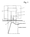
- Fig. 1 shows a dual-circuit shaft seal of a first embodiment.
- a sealing ring 2 is arranged from two separate Ring discourseen.
- the ring halves lie without axial thrust balance on the associated walls of the sealing ring housing 1.
- a vacuum oil supply 3 Associated with the sealing ring system is a vacuum oil supply 3 and a GasölZu arrangement 4.
- Vauum oil is to be understood that the oil is pure and in it no gas, especially air is dissolved.
- gas oil is meant that in the oil gas, namely hydrogen is dissolved.
- the vacuum oil supply 3 takes place through the radial slot between the two separate ring halves of the sealing ring 2.
- the gas oil feed 4 is formed in the sealing ring housing 1 and in one ring half of the sealing ring 2. Both feeds 3, 4 open radially in a radial sealing gap 5, which is formed between the radial inner side of the sealing ring 2 and the radial outer side of a rotor shaft 6 of an electric generator for power generation in power plants.
- the fixed sealing ring 2 is part of a housing of the electric generator, not shown, through which the rotor shaft 6 is rotatably guided.
- Fig. 1 shows the one implementation.
- the housing is filled with hydrogen.
- the Fig. 1 shows the so-called gas side (ie the interior of the housing of the generator) on the right and the so-called air side on the left, ie the environment of the generator.
- the two mouths of the feeders 3, 4 define a separating gap 7 between them.
- Degassed oil is supplied continuously via the vacuum oil feed 3. This oil flows in the direction of the air side (in the drawing to the left) and accumulates there with air, ie in the oil, air dissolves to saturation.
- gas oil supply 4 oil is supplied, in which hydrogen is dissolved to saturation. This flows (in the drawing to the right) into the interior of the housing of the electric generator, which - as stated - is filled with hydrogen.
- the pressure gradient in Fig. 1 indicates that the pressure of the vacuum oil and the gas oil is higher than the pressure of the hydrogen in the housing. This prevents hydrogen from leaking out of the housing through the seals.
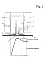
- FIG. 2 shows a somewhat modified embodiment of a dual-circuit shaft seal.
- the sealing ring 2 is integrally formed. It is associated with an axial thrust compensation by means of a pressure oil supply 8. This means that no solid contact between the sealing ring 2 and the walls of the sealing ring housing 1 exists.
- the sealing ring 2 is thus a swimming ring.
- Fig. 1 and 2 show two embodiments of a dual-circuit shaft seal.
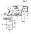
- Fig. 3 shows the complete oil circuits.
- the process scheme shows specifically the air / vacuum oil circuit (thin line) and the gas-oil circuit (thick line).
- the gas oil After passing through the shaft seal, the gas oil is fed to a defoaming tank 9. About a gas oil pump 10, a gas oil cooler 11 and a filter 12, the return of the gas oil to the two shaft seals.
- the defoaming tank 9 and a gas oil return control tank 13 constitute a system of communicating vessels.
- the degassed (vacuum) oil enriches after passing the shaft seals with air, so that from the vacuum oil before being supplied to the shaft seal an air oil after passing the shaft seal.
- the air oil After passing through an intermediate tank 14 with a ⁇ lldunstabsaugung 15, the air oil is supplied to a defoaming tank 16.
- the air oil is supplied to a vacuum oil tank 17 via a float-controlled control valve.
- a vacuum pump 18 provides for an evacuation of the oil tank, so that the air dissolved in the oil outgass and is discharged. This means that in the vacuum oil tank 17 in cooperation with the vacuum pump 18 from the air oil degassed vacuum oil is.
- the degassed vacuum oil is returned to the shaft seal via an air oil cooler 20 and a switchable double filter 21.
- the system also has a differential pressure regulator 22 and a pressure compensation regulator 23.
- a supply line 24 may be provided for an axial thrust balance, if it is in the shaft seal according to Fig. 2 is a shaft seal with axial thrust compensation.
- the gas oil circuit with the corresponding return control remains untouched and therefore works like a shaft seal, in which the so-called air oil is not degassed.
- the gas oil flows as a result of the control tolerance or stationarily set pressure difference across the separating gap 7 on the air side, where it mixes with the degassed vacuum oil and leaves with this the air side sealing gap 5.
- the gas-side return reservoirs are emptied until the left in the drawing float valve opens in the gas oil return control tank 13 and now flows instead of the air oil evacuated oil from the vacuum oil pressure line into the reservoirs.
- the hydrogen purity is not deteriorated thereby.
- a direct deterioration of the purity does not occur because there is no air in the vacuum oil due to the degassing.
- the gas side return reservoirs are filled until the right float valve opens in the gas oil return control tank 13 and the excess gas oil is diverted into the vacuum oil return line (suction line). Although there is a loss of hydrogen, the hydrogen purity remains unchanged.
Claims (2)
- Procédé pour faire fonctionner un générateur électrique pour la production de courant dans des centrales électriques, le générateur électrique étant pourvu :- d'un arbre rotor (6) présentant un enroulement,- d'un boîtier dans lequel l'arbre rotor (6) est monté tournant, ainsi que- de deux bagues d'étanchéité (2) aux deux points de passage de l'arbre rotor (6) à travers le boîtier,selon lequel procédé
le boîtier est rempli d'hydrogène et
de l'huile est amenée de façon continue pour l'étanchéité à la fente d'étanchéité radiale (5) entre la bague d'étanchéité (2) respective et l'arbre rotor (6) dans un circuit double en deux courants axiaux dirigés en sens contraire en laissant une fente de séparation (7) entre les deux, le premier courant étant dirigé vers l'intérieur du boîtier et le deuxième courant vers l'extérieur par rapport au boîtier,
caractérisé en ce
que l'air dissous est éliminé du deuxième courant avant que l'huile soit de nouveau amenée à la fente d'étanchéité (5). - Procédé selon la revendication précédente,
caractérisé en ce
que l'huile est exposée à un vide.
Applications Claiming Priority (1)
| Application Number | Priority Date | Filing Date | Title |
|---|---|---|---|
| DE102007059147 | 2007-12-07 |
Publications (2)
| Publication Number | Publication Date |
|---|---|
| EP2079151A1 EP2079151A1 (fr) | 2009-07-15 |
| EP2079151B1 true EP2079151B1 (fr) | 2010-07-28 |
Family
ID=40668207
Family Applications (1)
| Application Number | Title | Priority Date | Filing Date |
|---|---|---|---|
| EP08020488A Revoked EP2079151B1 (fr) | 2007-12-07 | 2008-11-26 | Procédé destiné au fonctionnement d'un générateur électrique pour la production d'énergie dans des centrales |
Country Status (3)
| Country | Link |
|---|---|
| EP (1) | EP2079151B1 (fr) |
| AT (1) | ATE476006T1 (fr) |
| DE (1) | DE502008001026D1 (fr) |
Cited By (1)
| Publication number | Priority date | Publication date | Assignee | Title |
|---|---|---|---|---|
| US20120098206A1 (en) * | 2010-10-22 | 2012-04-26 | Kabushiki Kaisha Toshiba | Seal oil feeding apparatus of rotating electrical machine |
Families Citing this family (5)
| Publication number | Priority date | Publication date | Assignee | Title |
|---|---|---|---|---|
| EP2309155A1 (fr) * | 2009-10-08 | 2011-04-13 | Alstom Technology Ltd | Système d'étanchéité d'un générateur électrique |
| EP2330324A1 (fr) * | 2009-12-07 | 2011-06-08 | Alstom Technology Ltd | Machine électrique scellée à sécurité améliorée |
| EP2628517A1 (fr) * | 2012-02-14 | 2013-08-21 | Siemens Aktiengesellschaft | Dispositif de dégazage d'un liquide d'étanchement |
| EP3243558A1 (fr) | 2016-05-10 | 2017-11-15 | General Electric Technology GmbH | Système de dégazage de pétrole industriel et procédé |
| CN109027248B (zh) * | 2018-10-10 | 2023-10-20 | 四川省机械研究设计院(集团)有限公司 | 一种抑制密封油窜流流量的氢冷发电机双流环密封瓦 |
Family Cites Families (8)
| Publication number | Priority date | Publication date | Assignee | Title |
|---|---|---|---|---|
| BE497973A (fr) * | 1949-09-13 | |||
| JPS56166742A (en) * | 1980-05-28 | 1981-12-22 | Toshiba Corp | Treating device for sealing oil |
| JPS5921251A (ja) * | 1982-07-28 | 1984-02-03 | Toshiba Corp | 回転電機の密封油供給装置 |
| DE3723729C2 (de) * | 1987-07-17 | 1994-06-09 | Siemens Ag | Wellendichtung, insbesondere für Wellen von gasgekühlten Generatoren |
| US4969796A (en) * | 1989-10-30 | 1990-11-13 | Westinghouse Electric Corp. | Method and apparatus for cooling shaft seals |
| CZ108595A3 (en) * | 1992-11-05 | 1995-08-16 | Siemens Ag | Device for exhausting waste gas containing hydrogen and residual gas from an electric machine being filled with nitrogen, and use thereof |
| US5603416A (en) | 1995-09-21 | 1997-02-18 | Campbell Hausfeld/Scott Fetzer Co. | Secure pneumatic tool display |
| EP1103746A1 (fr) | 1999-11-25 | 2001-05-30 | Siemens Aktiengesellschaft | Joint d'étanchéité pour arbre |
-
2008
- 2008-11-26 DE DE502008001026T patent/DE502008001026D1/de active Active
- 2008-11-26 AT AT08020488T patent/ATE476006T1/de active
- 2008-11-26 EP EP08020488A patent/EP2079151B1/fr not_active Revoked
Cited By (2)
| Publication number | Priority date | Publication date | Assignee | Title |
|---|---|---|---|---|
| US20120098206A1 (en) * | 2010-10-22 | 2012-04-26 | Kabushiki Kaisha Toshiba | Seal oil feeding apparatus of rotating electrical machine |
| US9093872B2 (en) * | 2010-10-22 | 2015-07-28 | Kabushiki Kaisha Toshiba | Seal oil feeding apparatus of rotating electrical machine |
Also Published As
| Publication number | Publication date |
|---|---|
| DE502008001026D1 (de) | 2010-09-09 |
| ATE476006T1 (de) | 2010-08-15 |
| EP2079151A1 (fr) | 2009-07-15 |
Similar Documents
| Publication | Publication Date | Title |
|---|---|---|
| EP2079151B1 (fr) | Procédé destiné au fonctionnement d'un générateur électrique pour la production d'énergie dans des centrales | |
| AT513836B1 (de) | Kompressor mit und Verfahren zur Spülung des Kompressorgehäuses mit Spülgas | |
| EP2326858A1 (fr) | Ensemble comprenant un joint d'arbre | |
| DE1901353C3 (de) | Schmiervorrichtung fur eine Gleitringdichtung | |
| DE102014201547A1 (de) | Turbolader | |
| DE1011050B (de) | Leckdichtung fuer gasgefuellte, elektrische Maschinen | |
| EP3805529A1 (fr) | Procédé de fonctionnement d'une turbomachine avec dioxyde de carbone | |
| EP2558710A1 (fr) | Ensemble pompe-turbine | |
| EP0025910A1 (fr) | Procédé et dispositif pour le dégazage d'un liquide sous pression d'un système hydraulique | |
| DE102014211690A1 (de) | Fluidenergiemaschine, Verfahren zum Betrieb | |
| DE820764C (de) | Verfahren zur Entlueftung der stroemenden Dichtungsfluessigkeit bei wasserstoffgekuehlten Maschinen | |
| EP3061974B1 (fr) | Système de refroidissement et de dégazage pour une pompe de transfert de chaleur | |
| EP0570086A1 (fr) | Triple garniture mécanique lubrifiée par gaz pour turbomachines | |
| EP2598724B1 (fr) | Turbine à vapeur et procédé pour refroidir une turbine à vapeur | |
| EP2816235B1 (fr) | Pompe à vide | |
| DE1074736B (fr) | ||
| DE19809957A1 (de) | Mehrwellenvakuumpumpe | |
| DE102014218937A1 (de) | Wellendichtung, Verfahren zum Betrieb | |
| DE102009021922B3 (de) | Staurohrpumpe | |
| DE2010403C3 (de) | Einrichtung zur Zu- und Abfuhrung einer Kühlflüssigkeit fur mindestens einen in dem Rotor einer elektrischen Maschine angeordneten Kuhlkanal | |
| DE3034715C2 (de) | Wellenabdichtung für gasgefüllte elektrische Maschinen | |
| EP3575641A1 (fr) | Dispositif, en particulier turbomachine comprenant un dispositif formant joint d'étanchéité d'arbre | |
| DE1428139C3 (de) | Flüssigkeitsringpumpe | |
| EP0713001A1 (fr) | Turbine de détente à gaz | |
| DE1120571B (de) | Einrichtung zur Abdichtung der Wellendurchfuehrungen an einem Turbogenerator mit im Vakuum rotierendem Laeufer |
Legal Events
| Date | Code | Title | Description |
|---|---|---|---|
| PUAI | Public reference made under article 153(3) epc to a published international application that has entered the european phase |
Free format text: ORIGINAL CODE: 0009012 |
|
| AK | Designated contracting states |
Kind code of ref document: A1 Designated state(s): AT BE BG CH CY CZ DE DK EE ES FI FR GB GR HR HU IE IS IT LI LT LU LV MC MT NL NO PL PT RO SE SI SK TR |
|
| AX | Request for extension of the european patent |
Extension state: AL BA MK RS |
|
| 17P | Request for examination filed |
Effective date: 20090925 |
|
| 17Q | First examination report despatched |
Effective date: 20091021 |
|
| AKX | Designation fees paid |
Designated state(s): AT BE BG CH CY CZ DE DK EE ES FI FR GB GR HR HU IE IS IT LI LT LU LV MC MT NL NO PL PT RO SE SI SK TR |
|
| GRAP | Despatch of communication of intention to grant a patent |
Free format text: ORIGINAL CODE: EPIDOSNIGR1 |
|
| GRAS | Grant fee paid |
Free format text: ORIGINAL CODE: EPIDOSNIGR3 |
|
| GRAA | (expected) grant |
Free format text: ORIGINAL CODE: 0009210 |
|
| AK | Designated contracting states |
Kind code of ref document: B1 Designated state(s): AT BE BG CH CY CZ DE DK EE ES FI FR GB GR HR HU IE IS IT LI LT LU LV MC MT NL NO PL PT RO SE SI SK TR |
|
| REG | Reference to a national code |
Ref country code: GB Ref legal event code: FG4D Free format text: NOT ENGLISH |
|
| REG | Reference to a national code |
Ref country code: CH Ref legal event code: EP |
|
| REG | Reference to a national code |
Ref country code: IE Ref legal event code: FG4D Free format text: LANGUAGE OF EP DOCUMENT: GERMAN |
|
| REF | Corresponds to: |
Ref document number: 502008001026 Country of ref document: DE Date of ref document: 20100909 Kind code of ref document: P |
|
| REG | Reference to a national code |
Ref country code: NL Ref legal event code: T3 |
|
| LTIE | Lt: invalidation of european patent or patent extension |
Effective date: 20100728 |
|
| PG25 | Lapsed in a contracting state [announced via postgrant information from national office to epo] |
Ref country code: NO Free format text: LAPSE BECAUSE OF FAILURE TO SUBMIT A TRANSLATION OF THE DESCRIPTION OR TO PAY THE FEE WITHIN THE PRESCRIBED TIME-LIMIT Effective date: 20101028 Ref country code: LT Free format text: LAPSE BECAUSE OF FAILURE TO SUBMIT A TRANSLATION OF THE DESCRIPTION OR TO PAY THE FEE WITHIN THE PRESCRIBED TIME-LIMIT Effective date: 20100728 Ref country code: FI Free format text: LAPSE BECAUSE OF FAILURE TO SUBMIT A TRANSLATION OF THE DESCRIPTION OR TO PAY THE FEE WITHIN THE PRESCRIBED TIME-LIMIT Effective date: 20100728 |
|
| PG25 | Lapsed in a contracting state [announced via postgrant information from national office to epo] |
Ref country code: BG Free format text: LAPSE BECAUSE OF FAILURE TO SUBMIT A TRANSLATION OF THE DESCRIPTION OR TO PAY THE FEE WITHIN THE PRESCRIBED TIME-LIMIT Effective date: 20101028 Ref country code: CY Free format text: LAPSE BECAUSE OF FAILURE TO SUBMIT A TRANSLATION OF THE DESCRIPTION OR TO PAY THE FEE WITHIN THE PRESCRIBED TIME-LIMIT Effective date: 20100728 Ref country code: HR Free format text: LAPSE BECAUSE OF FAILURE TO SUBMIT A TRANSLATION OF THE DESCRIPTION OR TO PAY THE FEE WITHIN THE PRESCRIBED TIME-LIMIT Effective date: 20100728 Ref country code: IS Free format text: LAPSE BECAUSE OF FAILURE TO SUBMIT A TRANSLATION OF THE DESCRIPTION OR TO PAY THE FEE WITHIN THE PRESCRIBED TIME-LIMIT Effective date: 20101128 Ref country code: PL Free format text: LAPSE BECAUSE OF FAILURE TO SUBMIT A TRANSLATION OF THE DESCRIPTION OR TO PAY THE FEE WITHIN THE PRESCRIBED TIME-LIMIT Effective date: 20100728 Ref country code: SI Free format text: LAPSE BECAUSE OF FAILURE TO SUBMIT A TRANSLATION OF THE DESCRIPTION OR TO PAY THE FEE WITHIN THE PRESCRIBED TIME-LIMIT Effective date: 20100728 |
|
| REG | Reference to a national code |
Ref country code: IE Ref legal event code: FD4D |
|
| PG25 | Lapsed in a contracting state [announced via postgrant information from national office to epo] |
Ref country code: GR Free format text: LAPSE BECAUSE OF FAILURE TO SUBMIT A TRANSLATION OF THE DESCRIPTION OR TO PAY THE FEE WITHIN THE PRESCRIBED TIME-LIMIT Effective date: 20101029 Ref country code: LV Free format text: LAPSE BECAUSE OF FAILURE TO SUBMIT A TRANSLATION OF THE DESCRIPTION OR TO PAY THE FEE WITHIN THE PRESCRIBED TIME-LIMIT Effective date: 20100728 Ref country code: SE Free format text: LAPSE BECAUSE OF FAILURE TO SUBMIT A TRANSLATION OF THE DESCRIPTION OR TO PAY THE FEE WITHIN THE PRESCRIBED TIME-LIMIT Effective date: 20100728 |
|
| PG25 | Lapsed in a contracting state [announced via postgrant information from national office to epo] |
Ref country code: DK Free format text: LAPSE BECAUSE OF FAILURE TO SUBMIT A TRANSLATION OF THE DESCRIPTION OR TO PAY THE FEE WITHIN THE PRESCRIBED TIME-LIMIT Effective date: 20100728 Ref country code: IE Free format text: LAPSE BECAUSE OF FAILURE TO SUBMIT A TRANSLATION OF THE DESCRIPTION OR TO PAY THE FEE WITHIN THE PRESCRIBED TIME-LIMIT Effective date: 20100728 |
|
| PLBI | Opposition filed |
Free format text: ORIGINAL CODE: 0009260 |
|
| PLAB | Opposition data, opponent's data or that of the opponent's representative modified |
Free format text: ORIGINAL CODE: 0009299OPPO |
|
| PLAX | Notice of opposition and request to file observation + time limit sent |
Free format text: ORIGINAL CODE: EPIDOSNOBS2 |
|
| PG25 | Lapsed in a contracting state [announced via postgrant information from national office to epo] |
Ref country code: CZ Free format text: LAPSE BECAUSE OF FAILURE TO SUBMIT A TRANSLATION OF THE DESCRIPTION OR TO PAY THE FEE WITHIN THE PRESCRIBED TIME-LIMIT Effective date: 20100728 Ref country code: RO Free format text: LAPSE BECAUSE OF FAILURE TO SUBMIT A TRANSLATION OF THE DESCRIPTION OR TO PAY THE FEE WITHIN THE PRESCRIBED TIME-LIMIT Effective date: 20100728 Ref country code: IT Free format text: LAPSE BECAUSE OF FAILURE TO SUBMIT A TRANSLATION OF THE DESCRIPTION OR TO PAY THE FEE WITHIN THE PRESCRIBED TIME-LIMIT Effective date: 20100728 Ref country code: EE Free format text: LAPSE BECAUSE OF FAILURE TO SUBMIT A TRANSLATION OF THE DESCRIPTION OR TO PAY THE FEE WITHIN THE PRESCRIBED TIME-LIMIT Effective date: 20100728 Ref country code: SK Free format text: LAPSE BECAUSE OF FAILURE TO SUBMIT A TRANSLATION OF THE DESCRIPTION OR TO PAY THE FEE WITHIN THE PRESCRIBED TIME-LIMIT Effective date: 20100728 |
|
| 26 | Opposition filed |
Opponent name: ALSTOM TECHNOLOGY LTD Effective date: 20110426 |
|
| R26 | Opposition filed (corrected) |
Opponent name: ALSTOM TECHNOLOGY LTD Effective date: 20110426 |
|
| PG25 | Lapsed in a contracting state [announced via postgrant information from national office to epo] |
Ref country code: ES Free format text: LAPSE BECAUSE OF FAILURE TO SUBMIT A TRANSLATION OF THE DESCRIPTION OR TO PAY THE FEE WITHIN THE PRESCRIBED TIME-LIMIT Effective date: 20101108 Ref country code: MC Free format text: LAPSE BECAUSE OF NON-PAYMENT OF DUE FEES Effective date: 20101130 |
|
| REG | Reference to a national code |
Ref country code: DE Ref legal event code: R026 Ref document number: 502008001026 Country of ref document: DE Effective date: 20110426 |
|
| REG | Reference to a national code |
Ref country code: FR Ref legal event code: ST Effective date: 20110801 |
|
| PLAF | Information modified related to communication of a notice of opposition and request to file observations + time limit |
Free format text: ORIGINAL CODE: EPIDOSCOBS2 |
|
| PG25 | Lapsed in a contracting state [announced via postgrant information from national office to epo] |
Ref country code: FR Free format text: LAPSE BECAUSE OF NON-PAYMENT OF DUE FEES Effective date: 20101130 |
|
| PLBB | Reply of patent proprietor to notice(s) of opposition received |
Free format text: ORIGINAL CODE: EPIDOSNOBS3 |
|
| PG25 | Lapsed in a contracting state [announced via postgrant information from national office to epo] |
Ref country code: MT Free format text: LAPSE BECAUSE OF FAILURE TO SUBMIT A TRANSLATION OF THE DESCRIPTION OR TO PAY THE FEE WITHIN THE PRESCRIBED TIME-LIMIT Effective date: 20100728 |
|
| PG25 | Lapsed in a contracting state [announced via postgrant information from national office to epo] |
Ref country code: LU Free format text: LAPSE BECAUSE OF NON-PAYMENT OF DUE FEES Effective date: 20101126 Ref country code: HU Free format text: LAPSE BECAUSE OF FAILURE TO SUBMIT A TRANSLATION OF THE DESCRIPTION OR TO PAY THE FEE WITHIN THE PRESCRIBED TIME-LIMIT Effective date: 20110129 |
|
| PG25 | Lapsed in a contracting state [announced via postgrant information from national office to epo] |
Ref country code: TR Free format text: LAPSE BECAUSE OF FAILURE TO SUBMIT A TRANSLATION OF THE DESCRIPTION OR TO PAY THE FEE WITHIN THE PRESCRIBED TIME-LIMIT Effective date: 20100728 |
|
| PGFP | Annual fee paid to national office [announced via postgrant information from national office to epo] |
Ref country code: GB Payment date: 20121122 Year of fee payment: 5 |
|
| REG | Reference to a national code |
Ref country code: CH Ref legal event code: PL |
|
| REG | Reference to a national code |
Ref country code: DE Ref legal event code: R064 Ref document number: 502008001026 Country of ref document: DE Ref country code: DE Ref legal event code: R103 Ref document number: 502008001026 Country of ref document: DE |
|
| PG25 | Lapsed in a contracting state [announced via postgrant information from national office to epo] |
Ref country code: PT Free format text: LAPSE BECAUSE OF NON-PAYMENT OF DUE FEES Effective date: 20100728 Ref country code: LI Free format text: LAPSE BECAUSE OF NON-PAYMENT OF DUE FEES Effective date: 20121130 Ref country code: CH Free format text: LAPSE BECAUSE OF NON-PAYMENT OF DUE FEES Effective date: 20121130 |
|
| RDAF | Communication despatched that patent is revoked |
Free format text: ORIGINAL CODE: EPIDOSNREV1 |
|
| RDAG | Patent revoked |
Free format text: ORIGINAL CODE: 0009271 |
|
| STAA | Information on the status of an ep patent application or granted ep patent |
Free format text: STATUS: PATENT REVOKED |
|
| PGFP | Annual fee paid to national office [announced via postgrant information from national office to epo] |
Ref country code: DE Payment date: 20130830 Year of fee payment: 6 |
|
| 27W | Patent revoked |
Effective date: 20130705 |
|
| GBPR | Gb: patent revoked under art. 102 of the ep convention designating the uk as contracting state |
Effective date: 20130705 |
|
| PGFP | Annual fee paid to national office [announced via postgrant information from national office to epo] |
Ref country code: BE Payment date: 20131121 Year of fee payment: 6 Ref country code: NL Payment date: 20131120 Year of fee payment: 6 |
|
| REG | Reference to a national code |
Ref country code: DE Ref legal event code: R107 Ref document number: 502008001026 Country of ref document: DE Effective date: 20140327 |
|
| REG | Reference to a national code |
Ref country code: AT Ref legal event code: MA03 Ref document number: 476006 Country of ref document: AT Kind code of ref document: T Effective date: 20130705 |