EP2079151B1 - Method of operating an electric generator to generate electricity in power plants - Google Patents
Method of operating an electric generator to generate electricity in power plants Download PDFInfo
- Publication number
- EP2079151B1 EP2079151B1 EP08020488A EP08020488A EP2079151B1 EP 2079151 B1 EP2079151 B1 EP 2079151B1 EP 08020488 A EP08020488 A EP 08020488A EP 08020488 A EP08020488 A EP 08020488A EP 2079151 B1 EP2079151 B1 EP 2079151B1
- Authority
- EP
- European Patent Office
- Prior art keywords
- oil
- hydrogen
- gas
- air
- housing
- Prior art date
- Legal status (The legal status is an assumption and is not a legal conclusion. Google has not performed a legal analysis and makes no representation as to the accuracy of the status listed.)
- Revoked
Links
Images
Classifications
-
- H—ELECTRICITY
- H02—GENERATION; CONVERSION OR DISTRIBUTION OF ELECTRIC POWER
- H02K—DYNAMO-ELECTRIC MACHINES
- H02K5/00—Casings; Enclosures; Supports
- H02K5/04—Casings or enclosures characterised by the shape, form or construction thereof
- H02K5/12—Casings or enclosures characterised by the shape, form or construction thereof specially adapted for operating in liquid or gas
- H02K5/124—Sealing of shafts
Definitions
- the invention relates to a method for operating an electric generator for power generation in power plants according to the preamble of claim 1.
- the resulting from energy conversion in the electric generator for power generation in power plants in the form of heat losses must be dissipated by a suitable cooling medium.
- a suitable cooling medium For larger generator unit performance, hydrogen is used as the cooling medium. This circulates under a certain overpressure relative to the environment in a pressure-resistant housing and with built-in recoolers using fans in one or more cooling circuits.
- the generator housing under pressure must be sealed at all necessary feedthroughs from the interior of the generator to the outside against leakage of hydrogen.
- the sealing of the shaft bushings on the front sides of the housing is given special care.
- the tightness is ensured on both sides of the generator (turbine side and exciter side) by a respective axial flow with oil narrow radial gap between the rotor shaft and the non-rotating sealing ring, characterized in that the oil pressure in the sealing gap greater than the hydrogen pressure in the housing is set.
- This basic concept of a shaft seal requires, on the one hand, a suitable structural design of the seal on the shaft itself and, on the other hand, a suitable oil supply device. This is usually arranged below the generator and contains corresponding components such as pumps, recoolers, filters, oil supply and oil removal pipelines and control devices, etc.
- the basic requirements of the shaft seal from the operator side are low hydrogen consumption and continuously high hydrogen purity in all operating conditions.
- the operator requires simple operability and reliable function even in long operating phases between two revision intervals.
- the hydrogen consumption requires a supply of fresh hydrogen with a purity of 100%. Because the reduction in hydrogen purity leads to an increase in the ventilation and gas friction losses, both of which are proportional to the mixture density. As the proportion of air increases, however, the mixture density is increased.
- This dual-circuit shaft seal works with two independent oil circuits, namely an 'air oil circuit' and a 'gas oil circuit'.
- air oil is to be understood in the following that the oil of this cycle is enriched with air, while the “gas oil”, the oil is enriched with the gas, namely hydrogen. These gases are each dissolved in the oil.
- the two radial sealing gaps through which air oil and gas oil pass are separated from one another by a so-called separating gap with a very small pressure gradient.
- This separation gap is the intermediate region between the initially radial and then axial flow of the air oil and the gas oil, wherein the two flow directions are directed in the radial sealing gap by 180 ° opposite.
- the pressure equality on both sides of the separating gap is enforced taking into account the regulatory deadlock by a pressure compensation control valve.
- the hydrogen in the generator is directly contaminated by air flowing through the separating gap with air oil, thus reducing its purity.
- there is also a loss of hydrogen since the increasingly filled by air oil gas oil cycle to its original Volume of oil must be returned by deriving the excess gas oil in the air tank.
- This flow through the separation gap is associated both with a direct loss of hydrogen and indirectly with a reduction in the purity of the hydrogen.
- the fundamental difference between the dual-circuit shaft seal and the other two shaft seal types mentioned is that this dual-circuit shaft seal operates without degassed oil.
- the air-saturated oil and the hydrogen-saturated oil are separated only by a separating gap with a relatively small pressure difference.
- the pressure gradient may arise from the tolerance of the control device alone, so that alternately air oil flows to the gas side and gas oil to the air side.
- the pressure gradient may intentionally be chosen in a preferred direction (but as small as possible), i. H. by using differential pressure regulators with the smallest possible setpoint range.
- the hydrogen consumption of a dual-circuit sealed oil system is thus composed of a direct loss of hydrogen, which then arises when gas oil flows through the separating gap on the air side and thereby the hydrogen dissolved in the oil is lost.
- an indirect hydrogen consumption which arises because the gas oil discharged on the air side must be replaced in order to replenish the gas-side return lines or the two dual-circuit systems conventional return reservoir.
- the filling can only be done with air oil.
- the hydrogen purity is deteriorated.
- the contaminated with air hydrogen must be replaced by pure hydrogen, ie fresh gas.
- the hydrogen purity is thus reduced independently of the flow direction of the separating gap at the same pressure gradient across the gap to the same extent.
- the EP 1 103 746 A1 shows a dual-circuit shaft seal in a generator with hydrogen cooling.
- a trained in the shaft seal sealing oil supply to the air side and a sealing oil supply to the gas side is provided.
- the WO 97/10740 A1 shows a single-circuit shaft seal for turbogenerators.
- the exhaust gas contained in the oil consisting of hydrogen and air is extracted, wherein separated in a further step, the hydrogen contained in the exhaust gas in a filter system and to is returned to the generator.
- the resulting hydrogen in the exhaust gas is not dissipated to the environment but continue to be used in the process cycle.
- the present invention seeks to provide a dual-circuit rotor shaft seal for hydrogen-cooled generators with minimal hydrogen consumption and constant maximum hydrogen purity.
- the oil is exposed to a vacuum.
- the idea of the invention is that the air-enriched oil (air oil) is degassed in a dedicated tank, d. H. that the air dissolved in the oil is extracted by evacuating the tank from the oil before the cleaned oil is returned to the seal.
- the conventional pumps for the air oil in the conventional art from the conventional sealing oil systems suck so no longer as previously enriched with air oil, but degassed oil from the vacuum oil tank and convey it to the same sealing gap, which provided in the conventional sealing oil system for the air oil was.
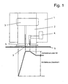
- Fig. 1 shows a dual-circuit shaft seal of a first embodiment.
- a sealing ring 2 is arranged from two separate Ring discourseen.
- the ring halves lie without axial thrust balance on the associated walls of the sealing ring housing 1.
- a vacuum oil supply 3 Associated with the sealing ring system is a vacuum oil supply 3 and a GasölZu arrangement 4.
- Vauum oil is to be understood that the oil is pure and in it no gas, especially air is dissolved.
- gas oil is meant that in the oil gas, namely hydrogen is dissolved.
- the vacuum oil supply 3 takes place through the radial slot between the two separate ring halves of the sealing ring 2.
- the gas oil feed 4 is formed in the sealing ring housing 1 and in one ring half of the sealing ring 2. Both feeds 3, 4 open radially in a radial sealing gap 5, which is formed between the radial inner side of the sealing ring 2 and the radial outer side of a rotor shaft 6 of an electric generator for power generation in power plants.
- the fixed sealing ring 2 is part of a housing of the electric generator, not shown, through which the rotor shaft 6 is rotatably guided.
- Fig. 1 shows the one implementation.
- the housing is filled with hydrogen.
- the Fig. 1 shows the so-called gas side (ie the interior of the housing of the generator) on the right and the so-called air side on the left, ie the environment of the generator.
- the two mouths of the feeders 3, 4 define a separating gap 7 between them.
- Degassed oil is supplied continuously via the vacuum oil feed 3. This oil flows in the direction of the air side (in the drawing to the left) and accumulates there with air, ie in the oil, air dissolves to saturation.
- gas oil supply 4 oil is supplied, in which hydrogen is dissolved to saturation. This flows (in the drawing to the right) into the interior of the housing of the electric generator, which - as stated - is filled with hydrogen.
- the pressure gradient in Fig. 1 indicates that the pressure of the vacuum oil and the gas oil is higher than the pressure of the hydrogen in the housing. This prevents hydrogen from leaking out of the housing through the seals.
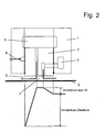
- FIG. 2 shows a somewhat modified embodiment of a dual-circuit shaft seal.
- the sealing ring 2 is integrally formed. It is associated with an axial thrust compensation by means of a pressure oil supply 8. This means that no solid contact between the sealing ring 2 and the walls of the sealing ring housing 1 exists.
- the sealing ring 2 is thus a swimming ring.
- Fig. 1 and 2 show two embodiments of a dual-circuit shaft seal.
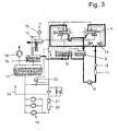
- Fig. 3 shows the complete oil circuits.
- the process scheme shows specifically the air / vacuum oil circuit (thin line) and the gas-oil circuit (thick line).
- the gas oil After passing through the shaft seal, the gas oil is fed to a defoaming tank 9. About a gas oil pump 10, a gas oil cooler 11 and a filter 12, the return of the gas oil to the two shaft seals.
- the defoaming tank 9 and a gas oil return control tank 13 constitute a system of communicating vessels.
- the degassed (vacuum) oil enriches after passing the shaft seals with air, so that from the vacuum oil before being supplied to the shaft seal an air oil after passing the shaft seal.
- the air oil After passing through an intermediate tank 14 with a ⁇ lldunstabsaugung 15, the air oil is supplied to a defoaming tank 16.
- the air oil is supplied to a vacuum oil tank 17 via a float-controlled control valve.
- a vacuum pump 18 provides for an evacuation of the oil tank, so that the air dissolved in the oil outgass and is discharged. This means that in the vacuum oil tank 17 in cooperation with the vacuum pump 18 from the air oil degassed vacuum oil is.
- the degassed vacuum oil is returned to the shaft seal via an air oil cooler 20 and a switchable double filter 21.
- the system also has a differential pressure regulator 22 and a pressure compensation regulator 23.
- a supply line 24 may be provided for an axial thrust balance, if it is in the shaft seal according to Fig. 2 is a shaft seal with axial thrust compensation.
- the gas oil circuit with the corresponding return control remains untouched and therefore works like a shaft seal, in which the so-called air oil is not degassed.
- the gas oil flows as a result of the control tolerance or stationarily set pressure difference across the separating gap 7 on the air side, where it mixes with the degassed vacuum oil and leaves with this the air side sealing gap 5.
- the gas-side return reservoirs are emptied until the left in the drawing float valve opens in the gas oil return control tank 13 and now flows instead of the air oil evacuated oil from the vacuum oil pressure line into the reservoirs.
- the hydrogen purity is not deteriorated thereby.
- a direct deterioration of the purity does not occur because there is no air in the vacuum oil due to the degassing.
- the gas side return reservoirs are filled until the right float valve opens in the gas oil return control tank 13 and the excess gas oil is diverted into the vacuum oil return line (suction line). Although there is a loss of hydrogen, the hydrogen purity remains unchanged.
Abstract
Description
Die Erfindung betrifft ein Verfahren zum Betreiben eines elektrischen Generators für die Stromgewinnung in Kraftwerken nach dem Oberbegriff des Anspruchs 1.The invention relates to a method for operating an electric generator for power generation in power plants according to the preamble of
Die durch Energieumsetzung im elektrischen Generator für die Stromgewinnung in Kraftwerken in Form von Wärme entstehenden Verluste müssen durch ein geeignetes Kühlmedium abgeführt werden. Für größere Generator-Einheitsleistungen wird als Kühlmedium Wasserstoff verwendet. Dieser zirkuliert unter einem gewissen Überdruck gegenüber der Umgebung in einem druckfesten Gehäuse und mit im Gehäuse eingebauten Rückkühlern mit Hilfe von Ventilatoren in einem oder mehreren Kühlungskreisläufen.The resulting from energy conversion in the electric generator for power generation in power plants in the form of heat losses must be dissipated by a suitable cooling medium. For larger generator unit performance, hydrogen is used as the cooling medium. This circulates under a certain overpressure relative to the environment in a pressure-resistant housing and with built-in recoolers using fans in one or more cooling circuits.
Dabei muß das unter Überdruck stehende Generatorgehäuse an allen notwendigen Durchführungen aus dem Innern des Generators nach außen gegen eine Leckage des Wasserstoffs abgedichtet werden. Der Abdichtung der Wellendurchführungen an den Stirnseiten des Gehäuses wird dabei besondere Sorgfalt gewidmet. Die Dichtheit wird auf beiden Seiten des Generators (Turbinenseite und Erregerseite) durch je einen axial mit Öl durchströmten engen Radialspalt zwischen der Rotorwelle und dem nicht rotierenden Dichtring dadurch gewährleistet, daß der Öldruck im Dichtspalt größer als der Wasserstoffdruck im Gehäuse eingestellt wird. Dieses Grundkonzept einer Wellendichtung erfordert einerseits eine geeignete konstruktive Ausbildung der Dichtung an der Welle selbst und andererseits eine geeignete Ölversorgungseinrichtung. Diese ist meist unterhalb des Generators angeordnet und enthält entsprechende Komponenten wie Pumpen, Rückkühler, Filter, Ölzuführungs- und Ölabführungsrohrleitungen sowie Regeleinrichtungen etc.In this case, the generator housing under pressure must be sealed at all necessary feedthroughs from the interior of the generator to the outside against leakage of hydrogen. The sealing of the shaft bushings on the front sides of the housing is given special care. The tightness is ensured on both sides of the generator (turbine side and exciter side) by a respective axial flow with oil narrow radial gap between the rotor shaft and the non-rotating sealing ring, characterized in that the oil pressure in the sealing gap greater than the hydrogen pressure in the housing is set. This basic concept of a shaft seal requires, on the one hand, a suitable structural design of the seal on the shaft itself and, on the other hand, a suitable oil supply device. This is usually arranged below the generator and contains corresponding components such as pumps, recoolers, filters, oil supply and oil removal pipelines and control devices, etc.
Die Grundanforderungen an die Wellendichtung von der Betreiberseite her sind niedriger Wasserstoffverbrauch sowie kontinuierlich hohe Wasserstoffreinheit in allen Betriebszuständen. Darüber hinaus werden vom Betreiber eine einfache Bedienbarkeit sowie eine zuverlässige Funktion selbst in langen Betriebsphasen zwischen zwei Revisionsintervallen verlangt. Der Wasserstoffverbrauch verlangt dabei eine Bereitstellung von frischem Wasserstoff mit einer Reinheit von 100%. Denn die Verringerung der Wasserstoffreinheit führt zu einer Erhöhung der Ventilations- und Gasreibungsverluste, welche beide der Gemischdichte proportional sind. Mit zunehmendem Luftanteil wird aber die Gemischdichte vergrößert.The basic requirements of the shaft seal from the operator side are low hydrogen consumption and continuously high hydrogen purity in all operating conditions. In addition, the operator requires simple operability and reliable function even in long operating phases between two revision intervals. The hydrogen consumption requires a supply of fresh hydrogen with a purity of 100%. Because the reduction in hydrogen purity leads to an increase in the ventilation and gas friction losses, both of which are proportional to the mixture density. As the proportion of air increases, however, the mixture density is increased.
Es gibt verschiedene Wellendichtungstypen, nämlich die Einkreislauf-Wellendichtung, die Zweikreislauf-Wellendichtung sowie die Dreikreislauf-Wellendichtung. Die vorliegende Erfindung geht von der Zweikreislauf-Wellendichtung aus.There are various shaft seal types, namely the single-shaft shaft seal, the dual-circuit shaft seal and the three-circuit shaft seal. The present invention is based on the dual-circuit shaft seal.
Diese Zweikreislauf-Wellendichtung arbeitet mit zwei voneinander unabhängigen Ölkreisläufen, nämlich einem "Luftöl-Kreislauf' und einem "Gasöl-Kreislauf'. Unter "Luftöl" ist dabei im nachfolgenden zu verstehen, daß das Öl dieses Kreislaufs mit Luft angereichert ist, während beim "Gasöl" das Öl mit dem Gas, nämlich Wasserstoff angereichert ist. Diese Gase sind jeweils in dem Öl gelöst.This dual-circuit shaft seal works with two independent oil circuits, namely an 'air oil circuit' and a 'gas oil circuit'. By "air oil" is to be understood in the following that the oil of this cycle is enriched with air, while the "gas oil", the oil is enriched with the gas, namely hydrogen. These gases are each dissolved in the oil.
Die beiden mit Luftöl und Gasöl durchströmten radialen Dichtspalte sind durch einen sogenannten Trennspalt mit sehr kleinem Druckgradienten voneinander separiert. Dieser Trennspalt ist der Zwischenbereich zwischen der zunächst radialen und dann axialen Strömung des Luftöls und des Gasöls, wobei die beiden Strömungsrichtungen im radialen Dichtspalt um 180° entgegengesetzt gerichtet sind. Die Druckgleichheit auf beiden Seiten des Trennspaltes wird unter Berücksichtigung der Regeltoteranz durch ein Druckausgleichsregelventil erzwungen.The two radial sealing gaps through which air oil and gas oil pass are separated from one another by a so-called separating gap with a very small pressure gradient. This separation gap is the intermediate region between the initially radial and then axial flow of the air oil and the gas oil, wherein the two flow directions are directed in the radial sealing gap by 180 ° opposite. The pressure equality on both sides of the separating gap is enforced taking into account the regulatory deadlock by a pressure compensation control valve.
Da der Luftöl-Kreislauf mit gelöster Luft und der Gasöl-Kreislauf mit gelöstem Wasserstoff im Bereich der radialen Dichtspalte an der Welle gesättigt sind, wird bei einer Durchströmung des Trennspaltes mit Luftöl der Wasserstoff im Generator durch Luft direkt kontaminiert und somit seine Reinheit verringert. Zusätzlich entsteht auch ein Verlust an Wasserstoff, da der zunehmend durch Luftöl aufgefüllte Gasöl-Kreislauf auf sein ursprüngliches Ölvolumen durch Ableiten des überschüssigen Gasöls in den Luftöltank zurückgeführt werden muß. Umgekehrt muß bei einer Durchströmung des Trennspaltes mit Gasöl wegen zunehmender Entleerung des Gasölkreises dieser mit Luftöl wieder aufgefüllt werden. Diese Durchströmung des Trennspaltes ist sowohl mit einem direkten Verlust an Wasserstoff als auch indirekt mit einer Verringerung der Reinheit des Wasserstoffs verbunden.Since the air-oil circuit is saturated with dissolved air and the gas-oil circuit with dissolved hydrogen in the radial sealing gaps on the shaft, the hydrogen in the generator is directly contaminated by air flowing through the separating gap with air oil, thus reducing its purity. In addition, there is also a loss of hydrogen, since the increasingly filled by air oil gas oil cycle to its original Volume of oil must be returned by deriving the excess gas oil in the air tank. Conversely, with a flow through the separating gap with gas oil due to increasing emptying of the gas oil circuit must be filled with air oil again. This flow through the separation gap is associated both with a direct loss of hydrogen and indirectly with a reduction in the purity of the hydrogen.
Somit führt die Durchströmung des Trennspaltes mit welchem der beiden gesättigten Öle auch immer stets zu einem Wasserstoffverlust und zu einer Verringerung der Wasserstoffreinheit. Dies ist mit einer Erhöhung der Ventilations- sowie Gasreibungsverluste verbunden.Thus, the flow through the separating gap with which of the two saturated oils always always leads to a loss of hydrogen and to a reduction in the hydrogen purity. This is associated with an increase in ventilation and gas friction losses.
Ein weiterer Nachteil dieses Dichtungstyps ist die Sensitivität des Trennspalts gegenüber Verunreinigungen des Öls. Feststoffpartikel können im Trennspalt viele Male umlaufen, bevor sie den Trennspalt verlassen. Dadurch ist ein Potential für Beschädigungen der Ringlauffläche und der Welle verbunden.Another disadvantage of this type of seal is the sensitivity of the separation gap to contamination of the oil. Solid particles can circulate many times in the separation gap before leaving the separation gap. As a result, a potential for damage to the ring raceway and the shaft is connected.
Der grundlegende Unterschied der Zweikreislauf-Wellendichtung zu den beiden anderen genannten Wellendichtungstypen ist, daß diese Zweikreislauf-Wellendichtung ohne entgastes Öl arbeitet. Das mit Luft gesättigte Öl und das mit Wasserstoff gesättigte Öl sind nur durch einen Trennspalt mit relativ geringer Druckdifferenz voneinander getrennt. Der Druckgradient kann sich aus der Toleranz der Regeleinrichtung allein ergeben, so daß abwechselnd Luftöl auf die Gasseite und Gasöl auf die Luftseite strömt. Außerdem kann der Druckgradient mit Absicht in einer bevorzugten Richtung (jedoch so klein wie möglich) gewählt werden, d. h. durch Verwendung von Differenzdruckreglern mit kleinstmöglichem Sollwertbereich.The fundamental difference between the dual-circuit shaft seal and the other two shaft seal types mentioned is that this dual-circuit shaft seal operates without degassed oil. The air-saturated oil and the hydrogen-saturated oil are separated only by a separating gap with a relatively small pressure difference. The pressure gradient may arise from the tolerance of the control device alone, so that alternately air oil flows to the gas side and gas oil to the air side. In addition, the pressure gradient may intentionally be chosen in a preferred direction (but as small as possible), i. H. by using differential pressure regulators with the smallest possible setpoint range.
Beide vorgenannte Einstellungen beeinflussen den Wasserstoffverlust und über die zeitlich zunehmende Verringerung der Reinheit indirekt den Wasserstoffverbrauch, weil die hohe Ausgangsreinheit wegen Minimierung der Ventilations- und Gasreibungsverluste durch Zuführung von Wasserstofffrischgas mit einer Reinheit von 100% wieder hergestellt werden muß. Da der Gaszustand (Druck und Temperatur) im Generator konstant bleiben soll, muß ein dem Frischgasstrom adäquater Gaststrom den Generator verlassen. Diese Bedingung führt zu einem zeitlich transienten Anstieg der Wasserstoffreinheit, der sich mit abnehmender Differenz zur Ausgangsreinheit (z. B. Ausgangsreinheit 99%) durch einen zunehmenden Frischgasverbrauch ausdrückt. Der weitaus größte Anteil des Wasserstoffverbrauchs ist daher mit der Verringerung der Wasserstoffreinheit verbunden.Both of the aforementioned settings indirectly affect hydrogen consumption and, over time reduction in purity, hydrogen consumption because high output purity must be restored by minimizing ventilation and gas friction losses by supplying 100% pure hydrogen fresh gas. Since the gas state (pressure and temperature) should remain constant in the generator, a fresh gas stream adequate gas flow must leave the generator. This condition leads to a time-transient increase in the hydrogen purity, which is expressed by decreasing difference from the initial purity (eg, 99% purity of the outlet) due to an increase in fresh gas consumption. The largest share of hydrogen consumption is therefore associated with the reduction of hydrogen purity.
Die Verringerung der Wasserstoffreiheit ist somit für die Erhöhung der Ventilation- und Gasreibungsverluste und für den weitaus größten Teil am Wasserstoffverbrauch verantwortlich.The reduction of hydrogen freedom is thus responsible for increasing the ventilation and gas friction losses and for the vast majority of hydrogen consumption.
Der Wasserstoffverbrauch einer Zweikreislauf-Dichtölanlage setzt sich also zusammen aus einem direkten Wasserstoffverlust, der dann entsteht, wenn Gasöl durch den Trennspalt auf die Luftseite strömt und dadurch der im Öl gelöste Wasserstoff verloren geht. Weiterhin besteht ein indirekter Wasserstoffverbrauch, der dadurch entsteht, daß das auf die Luftseite abgeströmte Gasöl ersetzt werden muß, um die gasseitigen Rücklaufleitungen bzw. die beiden Zweikreislauf-Anlagen üblichen Rücklaufreservoirs aufzufüllen. Das Auffüllen kann aber nur mit Luföl erfolgen. Dadurch aber wird die Wasserstoffreinheit verschlechtert. Um diese, wegen Beschränkung der Ventilations- und Gasreibungsverluste auf einem gewünschten, möglichst hohen Niveau zu halten, muß der mit Luft kontaminierte Wasserstoff durch reinen Wasserstoff, also Frischgas, ersetzt werden. Schließlich existiert noch ein indirekter Wasserstoffverbrauch, der dadurch entsteht, daß Luftöl auf die Gasseite strömt (axial im Trennspalt und radial im Spalt zwischen Dichtring und Gehäusewand) und damit die Wasserstoffreinheit im Generatorgehäuse direkt verringert. Auch hier muß reines Frischgas zugeführt werden, um die gewünschte Wasserstoffreinheit aufrechtzuerhalten. Hinzu kommt, daß das mit Luftöl aufgefüllte Gasöl in den Rücklaufreservoirs abgesteuert werden muß, um das ursprüngliche Niveau wieder herzustellen. Das überschüssige Gasöl kann aber nur in das Luftöl abgeführt werden. Dadurch geht der im Öl gelöste Wasserstoff direkt verloren.The hydrogen consumption of a dual-circuit sealed oil system is thus composed of a direct loss of hydrogen, which then arises when gas oil flows through the separating gap on the air side and thereby the hydrogen dissolved in the oil is lost. Furthermore, there is an indirect hydrogen consumption, which arises because the gas oil discharged on the air side must be replaced in order to replenish the gas-side return lines or the two dual-circuit systems conventional return reservoir. The filling can only be done with air oil. As a result, however, the hydrogen purity is deteriorated. To keep this, because of limitation of the ventilation and gas friction losses to a desired, the highest possible level, the contaminated with air hydrogen must be replaced by pure hydrogen, ie fresh gas. Finally, there is an indirect hydrogen consumption, which arises from the fact that air oil flows to the gas side (axially in the separating gap and radially in the gap between the sealing ring and the housing wall) and thus directly reduces the hydrogen purity in the generator housing. Again, pure fresh gas must be supplied to maintain the desired hydrogen purity. In addition, the gas oil filled with air oil must be disposed of in the return reservoirs to restore the original level. The excess gas oil can only be dissipated into the air oil. As a result, the dissolved hydrogen in the oil is lost directly.
Die Wasserstoffreinheit wird somit unabhängig von der Durchströmungsrichtung des Trennspaltes bei gleichen Druckgradienten über dem Spalt in gleichem Maße verringert.The hydrogen purity is thus reduced independently of the flow direction of the separating gap at the same pressure gradient across the gap to the same extent.
Ganz problematisch wird der Fall bei einem Ausfall der Gasölpumpe. Hier strömt Luftöl durch den gasseitigen Dichtspalt, wodurch die Reinheit massiv verschlechtert und der Wasserstoffverbrauch durch Frischgaszuführung bis zur Wiederinbetriebnahme der Gasölpumpe massiv erhöht werden muß, um die Reinheit des Wasserstoffs nicht unter einen kritischen Wert absinken zu lassen.Very problematic is the case in case of failure of the gas oil pump. Here, air oil flows through the gas-side sealing gap, whereby the purity deteriorates massively and the hydrogen consumption must be increased massively by Frischgaszuführung until recommissioning of the gas oil pump in order not to let the purity of the hydrogen fall below a critical value.
Die
Die
Davon ausgehend liegt der Erfindung die Aufgabe zugrunde, eine Zweikreislauf-Rotorwellendichtung für wasserstoffgekühlte Generatoren mit minimalem Wasserstoff-Verbrauch und zeitlich konstanter maximaler Wasserstoffreinheit zu schaffen.Based on this, the present invention seeks to provide a dual-circuit rotor shaft seal for hydrogen-cooled generators with minimal hydrogen consumption and constant maximum hydrogen purity.
Die technische Lösung ist gekennzeichnet durch die Merkmale im Kennzeichen des Anspruchs 1.The technical solution is characterized by the features in the characterizing part of
Vorzugsweise wird dabei gemäß der Weiterbildung in Anspruch 2 das Öl einem Vakuum ausgesetzt.Preferably, according to the embodiment in
Dadurch ist eine Zweikreislauf-Rotorwellendichtung für wasserstoffgekühlte Turbogeneratoren geschaffen, welche sich durch einen minimalen Verbrauch an Wasserstoff und einer zeitlich konstanten maximalen Reinheit des Wasserstoffs auszeichnet. Der Erfindungsgedanke besteht darin, daß das mit Luft angereicherte Öl (Luftöl) in einem eigens dafür vorgesehenen Tank entgast wird, d. h. daß die im Öl gelöste Luft durch Evakuieren des Tanks dem Öl entzogen wird, bevor das so gereinigte Öl wieder der Dichtung zugeführt wird. Die herkömmlichen Pumpen für das Luftöl bei den aus dem Stand der Technik konventionellen Dichtölanlagen saugen somit nunmehr nicht mehr wie bisher mit Luft angereichertes Öl an, sondern entgastes Öl aus dem Vakuumöltank und befördern es zum selben Dichtspalt, welcher in der konventionellen Dichtölanlage für das Luftöl vorgesehen war. Dies bedeutet aber, daß der Dichtring in seinen Abmessungen und seinen Radialspalten nicht geändert werden muß. Damit wird mit der erfindungsgemäßen Zweikreislauf-Wellendichtungsanlage eine sehr hohe Wasserstoffreinheit in allen Betriebszuständen des Generators stationär aufrechterhalten. Dadurch werden die Ventilations- und Gasreibungsverluste stationär minimiert. Auch bleibt der Wasserstoffverbrauch allein auf den Verlust in Folge Trennspaltströmung auf ein Minimum beschränkt. Für den Fall, daß die Gasölpumpe ausfallen sollte, strömt nunmehr das entgaste Öl anstatt Luftöl durch den gasseitigen Spalt, wodurch die Reinheit nicht verringert wird. Es muß nur ein erhöhter Wasserstoffverbrauch bis zur Wiederinbetriebnahme der Gasölpumpe in Kauf genommen werden.This creates a dual-circuit rotor shaft seal for hydrogen-cooled turbogenerators, which is characterized by a minimum consumption of hydrogen and a constant maximum purity of hydrogen over time. The idea of the invention is that the air-enriched oil (air oil) is degassed in a dedicated tank, d. H. that the air dissolved in the oil is extracted by evacuating the tank from the oil before the cleaned oil is returned to the seal. The conventional pumps for the air oil in the conventional art from the conventional sealing oil systems suck so no longer as previously enriched with air oil, but degassed oil from the vacuum oil tank and convey it to the same sealing gap, which provided in the conventional sealing oil system for the air oil was. However, this means that the sealing ring does not have to be changed in its dimensions and its radial gaps. Thus, a very high hydrogen purity is maintained stationary in all operating states of the generator with the dual-circuit shaft seal system according to the invention. As a result, the ventilation and gas friction losses are minimized stationary. Also, the hydrogen consumption is limited to the loss due to separation gap flow to a minimum. In the event that the gas oil pump should fail, now flows the degassed oil instead of air oil through the gas-side gap, whereby the purity is not reduced. It must be taken only an increased hydrogen consumption until recommissioning of the gas oil pump in purchasing.
Ein Ausführungsbeispiel für eine Zweikreislauf-Wellendichtung wird nachfolgend anhand der Zeichnungen beschrieben. In diesen zeigt:
- Fig. 1
- eine Zweikreislauf-Wellendichtung mit zwei getrennten Ring- hälften ohne Axialschubausgleich;
- Fig. 2
- eine Zweikreislauf-Wellendichtung mit einteiligem Ring sowie mit Axialschubausgleich;
- Fig. 3
- ein vereinfachtes Schema der Ölskreisläufe für eine Zweikreis- lauf-Wellendichtung der
Fig. 1 und 2 .
- Fig. 1
- a dual-circuit shaft seal with two separate halves without axial thrust compensation;
- Fig. 2
- a dual-circuit shaft seal with one-piece ring and with axial thrust compensation;
- Fig. 3
- a simplified diagram of the oil circuits for a dual-circuit shaft seal the
Fig. 1 and2 ,
Dem Dichtringsystem zugeordnet ist eine Vakuumöl-Zuführung 3 sowie eine GasölZuführung 4. Unter "Vakuumöl" ist dabei zu verstehen, daß das Öl rein ist und in ihm kein Gas, insbesondere Luft gelöst ist. Unter "Gasöl" ist zu verstehen, daß in dem Öl Gas, nämlich Wasserstoff gelöst ist.Associated with the sealing ring system is a
Die Vakuumöl-Zuführung 3 erfolgt durch den Radialschlitz zwischen den beiden getrennten Ringhälften des Dichtrings 2. Die Gasölzuführung 4 ist in dem Dichtringgehäuse 1 sowie in der einen Ringhälfte des Dichtrings 2 ausgebildet. Beide Zuführungen 3, 4 münden radial in einem radialen Dichtspalt 5, welcher zwischen der radialen Innenseite des Dichtrings 2 und der radialen Außenseite einer Rotorwelle 6 eines elektrischen Generators für die Stromgewinnung in Kraftwerken ausgebildet ist.The
Der feststehende Dichtring 2 ist Teil eines nicht dargestellten Gehäuses des elektrischen Generators, durch welchen hindurch die Rotorwelle 6 drehgelagert geführt ist.
Die beiden Mündungen der Zuführungen 3, 4 definieren zwischen sich einen Trennspalt 7.The two mouths of the
Die Funktionsweise der Wellendichtung ist wie folgt:The functioning of the shaft seal is as follows:
Über die Vakuumöl-Zuführung 3 wird entgastes Öl kontinuierlich zugeführt. Dieses Öl strömt in Richtung Luftseite (in der Zeichnung nach links) und reichert sich dort mit Luft an, d. h. in dem Öl löst sich Luft bis zur Sättigung.Degassed oil is supplied continuously via the
Durch die Gasöl-Zuführung 4 wird Öl zugeführt, in welchem Wasserstoff bis zur Sättigung gelöst ist. Dieses strömt (in der Zeichnung nach rechts) ins Innere des Gehäuses des elektrischen Generators, welches - wie ausgeführt - mit Wasserstoff gefüllt ist.Through the
Der Druckverlauf in
Da die Wellendichtung keinen Axialschubausgleich besitzt (dieser ist in der nachfolgenden
Die Ausführungsform in
Die
Das Verfahrensschema zeigt konkret den Luft/Vakuum-Öl-Kreislauf (dünne Linie) sowie den Gas-Öl-Kreislauf (dicke Linie).The process scheme shows specifically the air / vacuum oil circuit (thin line) and the gas-oil circuit (thick line).
Dargestellt sind zunächst in der Zeichnung rechts oben die beiden Wellendichtungen des Gehäuses, wie sie in
Nach Passieren der Wellendichtung wird das Gasöl einem Entschäumungstank 9 zugeführt. Über eine Gasöl-Pumpe 10, einem Gasöl-Kühler 11 und einem Filter 12 erfolgt die Rückleitung des Gasöls zu den beiden Wellendichtungen.After passing through the shaft seal, the gas oil is fed to a
Der Entschäumungstank 9 und ein Gasöl-Rücklaufregel-Behälter 13 bilden ein System von kommunizierenden Gefäßen.The
Das entgaste (Vakuum-)Öl reichert sich nach dem Passieren der Wellendichtungen mit Luft an, so daß aus dem Vakuumöl vor der Zuführung zur Wellendichtung ein Luftöl nach Passieren der Wellendichtung wird. Nach Passieren eines Zwischentanks 14 mit einer Öldunstabsaugung 15 wird das Luftöl einem Entschäumungstank 16 zugeführt.The degassed (vacuum) oil enriches after passing the shaft seals with air, so that from the vacuum oil before being supplied to the shaft seal an air oil after passing the shaft seal. After passing through an
Von dort aus wird das Luftöl über ein schwimmergesteuertes Regelventil einem Vakuumöltank 17 zugeführt. Eine Vakuumpumpe 18 sorgt für eine Evakuierung des Öltanks, so daß die im Öl gelöste Luft ausgast und abgeführt wird. Dies bedeutet, daß in dem Vakuumöltank 17 im Zusammenwirken mit der Vakuumpumpe 18 aus dem Luftöl entgastes Vakuumöl wird.From there, the air oil is supplied to a
Über Vakuumölpumpen 19 (mit Luftölpumpen/Wechselstrom sowie Luftölpumpen/Gleichstrom) wird über einen Luftöl-Kühler 20 sowie einem umschaltbaren Doppelfilter 21 das entgaste Vakuumöl wieder der Wellendichtung zugeführt.Via vacuum oil pumps 19 (with air oil pumps / alternating current and air oil pumps / direct current), the degassed vacuum oil is returned to the shaft seal via an
Weiterhin weist die Anlage noch einen Differenzdruckregler 22 sowie einen Druckausgleichsregler 23 auf.Furthermore, the system also has a
Optional kann noch eine Zuleitung 24 für einen Axialschubausgleich vorgesehen sein, wenn es sich bei der Wellendichtung gemäß
Der Gasöl-Kreislauf mit der entsprechenden Rücklaufregelung bleibt unangetastet und funktioniert daher wie bei einer Wellendichtung, bei welcher das sogenannte Luftöl nicht entgast wird.The gas oil circuit with the corresponding return control remains untouched and therefore works like a shaft seal, in which the so-called air oil is not degassed.
Das Gasöl strömt infolge der Regeltoleranz oder stationär eingestellter Druckdifferenz über dem Trennspalt 7 auf die Luftseite, vermischt sich dort mit dem entgasten Vakuumöl und verläßt mit diesem den luftseitigen Dichtspalt 5. Es entsteht dadurch ein direkter Wasserstoffverlust. Die gasseitigen Rücklaufreservoirs werden soweit entleert, bis das in der Zeichnung linke Schwimmerventil im Gasöl-Rücklaufregel-Behälter 13 öffnet und anstelle des Luftöls nunmehr evakuiertes Öl aus der Vakuumöl-Druckleitung in die Reservoirs einströmt. Dadurch wird die Wasserstoffreinheit aber nicht verschlechtert.The gas oil flows as a result of the control tolerance or stationarily set pressure difference across the separating
Vakuumöl strömt infolge der Regeltoleranz oder stationär eingestellter Druckdifferenz über dem Trennspalt 7 auf die Gasseite innerhalb des Generatorgehäuses, vermischt sich mit dem Gasöl und verläßt mit diesem den gasseitigen Dichtspalt 5. Eine direkte Verschlechterung der Reinheit tritt dabei nicht ein, weil sich in dem Vakuumöl aufgrund der Entgasung keine Luft befindet. Die gasseitigen Rücklaufreservoirs werden soweit aufgefüllt, bis das rechte Schwimmerventil im Gasöl-Rücklaufregel-Behälter 13 öffnet und das überschüssige Gasöl in die Vakuumöl-Rücklaufleitung (Saugleitung) abgesteuert wird. Es entsteht zwar ein Wasserstoffverlust, die Wasserstoffreinheit bleibt jedoch unverändert.Vacuum oil flows due to the control tolerance or stationarily set pressure difference across the separating
Somit entstehen für beide Durchströmungs-Richtungen des Trennspalts 7 bei gleichen eingestellten Druckdifferenzen gleiche Wasserstoffverluste. Man kann daher auch bei wechselnder Durchströmungsrichtung infolge der Regeltoleranz mit einem stationären, richtungsunabhängigen Druckgradienten rechnen.Thus arise for both flow directions of the
Weiterhin ist ein Ersatz der Backup-Ölzuführung vom Lageröltank durch eine weitere wechselstrombetriebene Dichtölpumpe der Vakuumölpumpen 19 realisiert. Dadurch wir die Zweikreislauf-Dichtölanlage unter Wahrung der Redundanz vom Lageröltank in der Ölzufuhr abgekoppelt und kann somit autonom betrieben werden.Furthermore, a replacement of the backup oil supply from the storage oil tank by a further AC-powered sealing oil pump of the
Um das Gefährdungspotential für den Trennspalt 7 durch Verunreinigungen im Öl in Form von Feststoffpartikeln zu verringern und die Ölaufwärmung im Spalt zu verringern, sollte über dem Trennspalt 7 eine geringe stationäre Druckdifferenz eingestellt werden.In order to reduce the risk potential for the
- 11
- DichtringgehäuseSeal case
- 22
- Dichtringseal
- 33
- Vakuumöl-ZuführungVacuum oil supply
- 44
- Gasöl-ZuführungGas oil supply
- 55
- Dichtspaltsealing gap
- 66
- Rotorwellerotor shaft
- 77
- Trennspaltseparating gap
- 88th
- Drucköl-ZuführungPressure oil supply
- 99
- Entschäumungstankdefoaming
- 1010
- Gasöl-PumpeGas oil pump
- 1111
- Gasöl-KühlerGas oil cooler
- 1212
- Filterfilter
- 1313
- Gasöl-Rücklaufregel-BehälterGas oil-return flow control tank
- 1414
- Zwischentankintermediate tank
- 1515
- ÖldunstabsaugungÖldunstabsaugung
- 1616
- Entschäumungstankdefoaming
- 1717
- VakuumöltankVacuum oil tank
- 1818
- Vakuumpumpevacuum pump
- 1919
- VakuumölpumpeVacuum pump oil
- 2020
- Luftöl-KühlerAir oil cooler
- 2121
- Doppelfilterdouble filter
- 2222
- DifferenzdruckreglerDifferential pressure regulator
- 2323
- Druckausg leichsreglerPressure equalizing regulator
- 2424
- Zuleitungsupply
Claims (2)
- Method for operating an electric generator to generate current in power stations, wherein the electric generator is provided:- with a rotor shaft (6) having a winding,- with a housing in which the rotor shaft (6) is rotatably mounted, and- with two sealing rings (2) at the two points where the rotor shaft (6) passes through the housing, wherein, in the method, the housing is filled with hydrogen and oil for the seal is continuously fed to the radial sealing gap (5) between the respective sealing ring (2) and the rotor shaft (6) in a dual circuit in two axial flows in opposite directions leaving a separating gap (7) in between, the first flow being directed into the interior of the housing and the second flow being directed outwardly with respect to the housing, characterised in that the released air is removed from the oil of the second flow before the oil is again fed to the sealing gap (5).
- Method according to the preceding claim, characterised in that the oil is subjected to a vacuum.
Applications Claiming Priority (1)
| Application Number | Priority Date | Filing Date | Title |
|---|---|---|---|
| DE102007059147 | 2007-12-07 |
Publications (2)
| Publication Number | Publication Date |
|---|---|
| EP2079151A1 EP2079151A1 (en) | 2009-07-15 |
| EP2079151B1 true EP2079151B1 (en) | 2010-07-28 |
Family
ID=40668207
Family Applications (1)
| Application Number | Title | Priority Date | Filing Date |
|---|---|---|---|
| EP08020488A Revoked EP2079151B1 (en) | 2007-12-07 | 2008-11-26 | Method of operating an electric generator to generate electricity in power plants |
Country Status (3)
| Country | Link |
|---|---|
| EP (1) | EP2079151B1 (en) |
| AT (1) | ATE476006T1 (en) |
| DE (1) | DE502008001026D1 (en) |
Cited By (1)
| Publication number | Priority date | Publication date | Assignee | Title |
|---|---|---|---|---|
| US20120098206A1 (en) * | 2010-10-22 | 2012-04-26 | Kabushiki Kaisha Toshiba | Seal oil feeding apparatus of rotating electrical machine |
Families Citing this family (5)
| Publication number | Priority date | Publication date | Assignee | Title |
|---|---|---|---|---|
| EP2309155A1 (en) * | 2009-10-08 | 2011-04-13 | Alstom Technology Ltd | Sealing system of a sealed electric generator |
| EP2330324A1 (en) * | 2009-12-07 | 2011-06-08 | Alstom Technology Ltd | Security improved sealed electric machine |
| EP2628517A1 (en) * | 2012-02-14 | 2013-08-21 | Siemens Aktiengesellschaft | Method for removing gas from a sealing liquid |
| EP3243558A1 (en) * | 2016-05-10 | 2017-11-15 | General Electric Technology GmbH | An industrial oil degassing system and method |
| CN109027248B (en) * | 2018-10-10 | 2023-10-20 | 四川省机械研究设计院(集团)有限公司 | Hydrogen-cooled generator double-flow-ring sealing tile for inhibiting flow of sealing oil channeling |
Family Cites Families (8)
| Publication number | Priority date | Publication date | Assignee | Title |
|---|---|---|---|---|
| BE497973A (en) * | 1949-09-13 | |||
| JPS56166742A (en) * | 1980-05-28 | 1981-12-22 | Toshiba Corp | Treating device for sealing oil |
| JPS5921251A (en) * | 1982-07-28 | 1984-02-03 | Toshiba Corp | Sealing oil supplying device for rotary electric machine |
| DE3723729C2 (en) * | 1987-07-17 | 1994-06-09 | Siemens Ag | Shaft seal, especially for gas-cooled generator shafts |
| US4969796A (en) * | 1989-10-30 | 1990-11-13 | Westinghouse Electric Corp. | Method and apparatus for cooling shaft seals |
| RU95110688A (en) * | 1992-11-05 | 1996-12-10 | Сименс АГ (DE) | Device which removes exhaust gas which contains hydrogen and residual gases from electric machine which is filled with hydrogen |
| US5603416A (en) | 1995-09-21 | 1997-02-18 | Campbell Hausfeld/Scott Fetzer Co. | Secure pneumatic tool display |
| EP1103746A1 (en) | 1999-11-25 | 2001-05-30 | Siemens Aktiengesellschaft | Shaft seal |
-
2008
- 2008-11-26 AT AT08020488T patent/ATE476006T1/en active
- 2008-11-26 DE DE502008001026T patent/DE502008001026D1/en active Active
- 2008-11-26 EP EP08020488A patent/EP2079151B1/en not_active Revoked
Cited By (2)
| Publication number | Priority date | Publication date | Assignee | Title |
|---|---|---|---|---|
| US20120098206A1 (en) * | 2010-10-22 | 2012-04-26 | Kabushiki Kaisha Toshiba | Seal oil feeding apparatus of rotating electrical machine |
| US9093872B2 (en) * | 2010-10-22 | 2015-07-28 | Kabushiki Kaisha Toshiba | Seal oil feeding apparatus of rotating electrical machine |
Also Published As
| Publication number | Publication date |
|---|---|
| ATE476006T1 (en) | 2010-08-15 |
| DE502008001026D1 (en) | 2010-09-09 |
| EP2079151A1 (en) | 2009-07-15 |
Similar Documents
| Publication | Publication Date | Title |
|---|---|---|
| EP2079151B1 (en) | Method of operating an electric generator to generate electricity in power plants | |
| AT513836B1 (en) | Compressor with and method for flushing the compressor housing with purge gas | |
| EP2326858A1 (en) | Arrangement comprising a shaft seal | |
| DE3105389C2 (en) | Canned motor pump | |
| DE102014201547A1 (en) | TURBOCHARGER | |
| DE1901353B2 (en) | Lubricating device for a mechanical seal | |
| DE1011050B (en) | Leak seal for gas-filled electrical machines | |
| EP0025910A1 (en) | Process and apparatus for the degasification of compressed fluid in a hydraulic system | |
| WO2013004321A1 (en) | Pump-turbine system | |
| DE102014211690A1 (en) | Fluid energy machine, method of operation | |
| DE820764C (en) | Process for venting the flowing sealing fluid in hydrogen-cooled machines | |
| EP3365532B1 (en) | Dry gas sealing system, and turbomachine comprising a dry gas sealing system | |
| EP3061974B1 (en) | Cooling and degassing system for a heat transfer pump | |
| EP0570086A1 (en) | Gas lubricated triple-mechanical seal for turbomachines | |
| EP2598724B1 (en) | Steam turbine and process for cooling such a steam turbine | |
| EP2816235B1 (en) | Vacuum pump | |
| DE19809957A1 (en) | Multi-shaft vacuum pump | |
| DE1074736B (en) | ||
| DE102014218937A1 (en) | Shaft seal, method of operation | |
| EP3775631B1 (en) | Arrangement, in particular turbomachine, comprising a shaft seal arrangement | |
| DE102009021922B3 (en) | Pitot tube pump | |
| DE2010403C3 (en) | Device for supplying and removing a cooling liquid for at least one cooling duct arranged in the rotor of an electrical machine | |
| DE3034715C2 (en) | Shaft seal for gas-filled electrical machines | |
| DE1428139C3 (en) | Liquid ring pump | |
| EP0713001A1 (en) | Gas turbine expander |
Legal Events
| Date | Code | Title | Description |
|---|---|---|---|
| PUAI | Public reference made under article 153(3) epc to a published international application that has entered the european phase |
Free format text: ORIGINAL CODE: 0009012 |
|
| AK | Designated contracting states |
Kind code of ref document: A1 Designated state(s): AT BE BG CH CY CZ DE DK EE ES FI FR GB GR HR HU IE IS IT LI LT LU LV MC MT NL NO PL PT RO SE SI SK TR |
|
| AX | Request for extension of the european patent |
Extension state: AL BA MK RS |
|
| 17P | Request for examination filed |
Effective date: 20090925 |
|
| 17Q | First examination report despatched |
Effective date: 20091021 |
|
| AKX | Designation fees paid |
Designated state(s): AT BE BG CH CY CZ DE DK EE ES FI FR GB GR HR HU IE IS IT LI LT LU LV MC MT NL NO PL PT RO SE SI SK TR |
|
| GRAP | Despatch of communication of intention to grant a patent |
Free format text: ORIGINAL CODE: EPIDOSNIGR1 |
|
| GRAS | Grant fee paid |
Free format text: ORIGINAL CODE: EPIDOSNIGR3 |
|
| GRAA | (expected) grant |
Free format text: ORIGINAL CODE: 0009210 |
|
| AK | Designated contracting states |
Kind code of ref document: B1 Designated state(s): AT BE BG CH CY CZ DE DK EE ES FI FR GB GR HR HU IE IS IT LI LT LU LV MC MT NL NO PL PT RO SE SI SK TR |
|
| REG | Reference to a national code |
Ref country code: GB Ref legal event code: FG4D Free format text: NOT ENGLISH |
|
| REG | Reference to a national code |
Ref country code: CH Ref legal event code: EP |
|
| REG | Reference to a national code |
Ref country code: IE Ref legal event code: FG4D Free format text: LANGUAGE OF EP DOCUMENT: GERMAN |
|
| REF | Corresponds to: |
Ref document number: 502008001026 Country of ref document: DE Date of ref document: 20100909 Kind code of ref document: P |
|
| REG | Reference to a national code |
Ref country code: NL Ref legal event code: T3 |
|
| LTIE | Lt: invalidation of european patent or patent extension |
Effective date: 20100728 |
|
| PG25 | Lapsed in a contracting state [announced via postgrant information from national office to epo] |
Ref country code: NO Free format text: LAPSE BECAUSE OF FAILURE TO SUBMIT A TRANSLATION OF THE DESCRIPTION OR TO PAY THE FEE WITHIN THE PRESCRIBED TIME-LIMIT Effective date: 20101028 Ref country code: LT Free format text: LAPSE BECAUSE OF FAILURE TO SUBMIT A TRANSLATION OF THE DESCRIPTION OR TO PAY THE FEE WITHIN THE PRESCRIBED TIME-LIMIT Effective date: 20100728 Ref country code: FI Free format text: LAPSE BECAUSE OF FAILURE TO SUBMIT A TRANSLATION OF THE DESCRIPTION OR TO PAY THE FEE WITHIN THE PRESCRIBED TIME-LIMIT Effective date: 20100728 |
|
| PG25 | Lapsed in a contracting state [announced via postgrant information from national office to epo] |
Ref country code: BG Free format text: LAPSE BECAUSE OF FAILURE TO SUBMIT A TRANSLATION OF THE DESCRIPTION OR TO PAY THE FEE WITHIN THE PRESCRIBED TIME-LIMIT Effective date: 20101028 Ref country code: CY Free format text: LAPSE BECAUSE OF FAILURE TO SUBMIT A TRANSLATION OF THE DESCRIPTION OR TO PAY THE FEE WITHIN THE PRESCRIBED TIME-LIMIT Effective date: 20100728 Ref country code: HR Free format text: LAPSE BECAUSE OF FAILURE TO SUBMIT A TRANSLATION OF THE DESCRIPTION OR TO PAY THE FEE WITHIN THE PRESCRIBED TIME-LIMIT Effective date: 20100728 Ref country code: IS Free format text: LAPSE BECAUSE OF FAILURE TO SUBMIT A TRANSLATION OF THE DESCRIPTION OR TO PAY THE FEE WITHIN THE PRESCRIBED TIME-LIMIT Effective date: 20101128 Ref country code: PL Free format text: LAPSE BECAUSE OF FAILURE TO SUBMIT A TRANSLATION OF THE DESCRIPTION OR TO PAY THE FEE WITHIN THE PRESCRIBED TIME-LIMIT Effective date: 20100728 Ref country code: SI Free format text: LAPSE BECAUSE OF FAILURE TO SUBMIT A TRANSLATION OF THE DESCRIPTION OR TO PAY THE FEE WITHIN THE PRESCRIBED TIME-LIMIT Effective date: 20100728 |
|
| REG | Reference to a national code |
Ref country code: IE Ref legal event code: FD4D |
|
| PG25 | Lapsed in a contracting state [announced via postgrant information from national office to epo] |
Ref country code: GR Free format text: LAPSE BECAUSE OF FAILURE TO SUBMIT A TRANSLATION OF THE DESCRIPTION OR TO PAY THE FEE WITHIN THE PRESCRIBED TIME-LIMIT Effective date: 20101029 Ref country code: LV Free format text: LAPSE BECAUSE OF FAILURE TO SUBMIT A TRANSLATION OF THE DESCRIPTION OR TO PAY THE FEE WITHIN THE PRESCRIBED TIME-LIMIT Effective date: 20100728 Ref country code: SE Free format text: LAPSE BECAUSE OF FAILURE TO SUBMIT A TRANSLATION OF THE DESCRIPTION OR TO PAY THE FEE WITHIN THE PRESCRIBED TIME-LIMIT Effective date: 20100728 |
|
| PG25 | Lapsed in a contracting state [announced via postgrant information from national office to epo] |
Ref country code: DK Free format text: LAPSE BECAUSE OF FAILURE TO SUBMIT A TRANSLATION OF THE DESCRIPTION OR TO PAY THE FEE WITHIN THE PRESCRIBED TIME-LIMIT Effective date: 20100728 Ref country code: IE Free format text: LAPSE BECAUSE OF FAILURE TO SUBMIT A TRANSLATION OF THE DESCRIPTION OR TO PAY THE FEE WITHIN THE PRESCRIBED TIME-LIMIT Effective date: 20100728 |
|
| PLBI | Opposition filed |
Free format text: ORIGINAL CODE: 0009260 |
|
| PLAB | Opposition data, opponent's data or that of the opponent's representative modified |
Free format text: ORIGINAL CODE: 0009299OPPO |
|
| PLAX | Notice of opposition and request to file observation + time limit sent |
Free format text: ORIGINAL CODE: EPIDOSNOBS2 |
|
| PG25 | Lapsed in a contracting state [announced via postgrant information from national office to epo] |
Ref country code: CZ Free format text: LAPSE BECAUSE OF FAILURE TO SUBMIT A TRANSLATION OF THE DESCRIPTION OR TO PAY THE FEE WITHIN THE PRESCRIBED TIME-LIMIT Effective date: 20100728 Ref country code: RO Free format text: LAPSE BECAUSE OF FAILURE TO SUBMIT A TRANSLATION OF THE DESCRIPTION OR TO PAY THE FEE WITHIN THE PRESCRIBED TIME-LIMIT Effective date: 20100728 Ref country code: IT Free format text: LAPSE BECAUSE OF FAILURE TO SUBMIT A TRANSLATION OF THE DESCRIPTION OR TO PAY THE FEE WITHIN THE PRESCRIBED TIME-LIMIT Effective date: 20100728 Ref country code: EE Free format text: LAPSE BECAUSE OF FAILURE TO SUBMIT A TRANSLATION OF THE DESCRIPTION OR TO PAY THE FEE WITHIN THE PRESCRIBED TIME-LIMIT Effective date: 20100728 Ref country code: SK Free format text: LAPSE BECAUSE OF FAILURE TO SUBMIT A TRANSLATION OF THE DESCRIPTION OR TO PAY THE FEE WITHIN THE PRESCRIBED TIME-LIMIT Effective date: 20100728 |
|
| 26 | Opposition filed |
Opponent name: ALSTOM TECHNOLOGY LTD Effective date: 20110426 |
|
| R26 | Opposition filed (corrected) |
Opponent name: ALSTOM TECHNOLOGY LTD Effective date: 20110426 |
|
| PG25 | Lapsed in a contracting state [announced via postgrant information from national office to epo] |
Ref country code: ES Free format text: LAPSE BECAUSE OF FAILURE TO SUBMIT A TRANSLATION OF THE DESCRIPTION OR TO PAY THE FEE WITHIN THE PRESCRIBED TIME-LIMIT Effective date: 20101108 Ref country code: MC Free format text: LAPSE BECAUSE OF NON-PAYMENT OF DUE FEES Effective date: 20101130 |
|
| REG | Reference to a national code |
Ref country code: DE Ref legal event code: R026 Ref document number: 502008001026 Country of ref document: DE Effective date: 20110426 |
|
| REG | Reference to a national code |
Ref country code: FR Ref legal event code: ST Effective date: 20110801 |
|
| PLAF | Information modified related to communication of a notice of opposition and request to file observations + time limit |
Free format text: ORIGINAL CODE: EPIDOSCOBS2 |
|
| PG25 | Lapsed in a contracting state [announced via postgrant information from national office to epo] |
Ref country code: FR Free format text: LAPSE BECAUSE OF NON-PAYMENT OF DUE FEES Effective date: 20101130 |
|
| PLBB | Reply of patent proprietor to notice(s) of opposition received |
Free format text: ORIGINAL CODE: EPIDOSNOBS3 |
|
| PG25 | Lapsed in a contracting state [announced via postgrant information from national office to epo] |
Ref country code: MT Free format text: LAPSE BECAUSE OF FAILURE TO SUBMIT A TRANSLATION OF THE DESCRIPTION OR TO PAY THE FEE WITHIN THE PRESCRIBED TIME-LIMIT Effective date: 20100728 |
|
| PG25 | Lapsed in a contracting state [announced via postgrant information from national office to epo] |
Ref country code: LU Free format text: LAPSE BECAUSE OF NON-PAYMENT OF DUE FEES Effective date: 20101126 Ref country code: HU Free format text: LAPSE BECAUSE OF FAILURE TO SUBMIT A TRANSLATION OF THE DESCRIPTION OR TO PAY THE FEE WITHIN THE PRESCRIBED TIME-LIMIT Effective date: 20110129 |
|
| PG25 | Lapsed in a contracting state [announced via postgrant information from national office to epo] |
Ref country code: TR Free format text: LAPSE BECAUSE OF FAILURE TO SUBMIT A TRANSLATION OF THE DESCRIPTION OR TO PAY THE FEE WITHIN THE PRESCRIBED TIME-LIMIT Effective date: 20100728 |
|
| PGFP | Annual fee paid to national office [announced via postgrant information from national office to epo] |
Ref country code: GB Payment date: 20121122 Year of fee payment: 5 |
|
| REG | Reference to a national code |
Ref country code: CH Ref legal event code: PL |
|
| REG | Reference to a national code |
Ref country code: DE Ref legal event code: R064 Ref document number: 502008001026 Country of ref document: DE Ref country code: DE Ref legal event code: R103 Ref document number: 502008001026 Country of ref document: DE |
|
| PG25 | Lapsed in a contracting state [announced via postgrant information from national office to epo] |
Ref country code: PT Free format text: LAPSE BECAUSE OF NON-PAYMENT OF DUE FEES Effective date: 20100728 Ref country code: LI Free format text: LAPSE BECAUSE OF NON-PAYMENT OF DUE FEES Effective date: 20121130 Ref country code: CH Free format text: LAPSE BECAUSE OF NON-PAYMENT OF DUE FEES Effective date: 20121130 |
|
| RDAF | Communication despatched that patent is revoked |
Free format text: ORIGINAL CODE: EPIDOSNREV1 |
|
| RDAG | Patent revoked |
Free format text: ORIGINAL CODE: 0009271 |
|
| STAA | Information on the status of an ep patent application or granted ep patent |
Free format text: STATUS: PATENT REVOKED |
|
| PGFP | Annual fee paid to national office [announced via postgrant information from national office to epo] |
Ref country code: DE Payment date: 20130830 Year of fee payment: 6 |
|
| 27W | Patent revoked |
Effective date: 20130705 |
|
| GBPR | Gb: patent revoked under art. 102 of the ep convention designating the uk as contracting state |
Effective date: 20130705 |
|
| PGFP | Annual fee paid to national office [announced via postgrant information from national office to epo] |
Ref country code: BE Payment date: 20131121 Year of fee payment: 6 Ref country code: NL Payment date: 20131120 Year of fee payment: 6 |
|
| REG | Reference to a national code |
Ref country code: DE Ref legal event code: R107 Ref document number: 502008001026 Country of ref document: DE Effective date: 20140327 |
|
| REG | Reference to a national code |
Ref country code: AT Ref legal event code: MA03 Ref document number: 476006 Country of ref document: AT Kind code of ref document: T Effective date: 20130705 |