EP2076737B1 - Bedienelement für ein kraftfahrzeug mit einem impulsgeber - Google Patents
Bedienelement für ein kraftfahrzeug mit einem impulsgeber Download PDFInfo
- Publication number
- EP2076737B1 EP2076737B1 EP07818434A EP07818434A EP2076737B1 EP 2076737 B1 EP2076737 B1 EP 2076737B1 EP 07818434 A EP07818434 A EP 07818434A EP 07818434 A EP07818434 A EP 07818434A EP 2076737 B1 EP2076737 B1 EP 2076737B1
- Authority
- EP
- European Patent Office
- Prior art keywords
- light
- distribution unit
- operating element
- light distribution
- light source
- Prior art date
- Legal status (The legal status is an assumption and is not a legal conclusion. Google has not performed a legal analysis and makes no representation as to the accuracy of the status listed.)
- Not-in-force
Links
Images

Classifications
-
- G—PHYSICS
- G01—MEASURING; TESTING
- G01D—MEASURING NOT SPECIALLY ADAPTED FOR A SPECIFIC VARIABLE; ARRANGEMENTS FOR MEASURING TWO OR MORE VARIABLES NOT COVERED IN A SINGLE OTHER SUBCLASS; TARIFF METERING APPARATUS; MEASURING OR TESTING NOT OTHERWISE PROVIDED FOR
- G01D5/00—Mechanical means for transferring the output of a sensing member; Means for converting the output of a sensing member to another variable where the form or nature of the sensing member does not constrain the means for converting; Transducers not specially adapted for a specific variable
- G01D5/26—Mechanical means for transferring the output of a sensing member; Means for converting the output of a sensing member to another variable where the form or nature of the sensing member does not constrain the means for converting; Transducers not specially adapted for a specific variable characterised by optical transfer means, i.e. using infrared, visible, or ultraviolet light
- G01D5/32—Mechanical means for transferring the output of a sensing member; Means for converting the output of a sensing member to another variable where the form or nature of the sensing member does not constrain the means for converting; Transducers not specially adapted for a specific variable characterised by optical transfer means, i.e. using infrared, visible, or ultraviolet light with attenuation or whole or partial obturation of beams of light
- G01D5/34—Mechanical means for transferring the output of a sensing member; Means for converting the output of a sensing member to another variable where the form or nature of the sensing member does not constrain the means for converting; Transducers not specially adapted for a specific variable characterised by optical transfer means, i.e. using infrared, visible, or ultraviolet light with attenuation or whole or partial obturation of beams of light the beams of light being detected by photocells
- G01D5/347—Mechanical means for transferring the output of a sensing member; Means for converting the output of a sensing member to another variable where the form or nature of the sensing member does not constrain the means for converting; Transducers not specially adapted for a specific variable characterised by optical transfer means, i.e. using infrared, visible, or ultraviolet light with attenuation or whole or partial obturation of beams of light the beams of light being detected by photocells using displacement encoding scales
- G01D5/3473—Circular or rotary encoders
-
- G—PHYSICS
- G01—MEASURING; TESTING
- G01D—MEASURING NOT SPECIALLY ADAPTED FOR A SPECIFIC VARIABLE; ARRANGEMENTS FOR MEASURING TWO OR MORE VARIABLES NOT COVERED IN A SINGLE OTHER SUBCLASS; TARIFF METERING APPARATUS; MEASURING OR TESTING NOT OTHERWISE PROVIDED FOR
- G01D5/00—Mechanical means for transferring the output of a sensing member; Means for converting the output of a sensing member to another variable where the form or nature of the sensing member does not constrain the means for converting; Transducers not specially adapted for a specific variable
- G01D5/26—Mechanical means for transferring the output of a sensing member; Means for converting the output of a sensing member to another variable where the form or nature of the sensing member does not constrain the means for converting; Transducers not specially adapted for a specific variable characterised by optical transfer means, i.e. using infrared, visible, or ultraviolet light
- G01D5/32—Mechanical means for transferring the output of a sensing member; Means for converting the output of a sensing member to another variable where the form or nature of the sensing member does not constrain the means for converting; Transducers not specially adapted for a specific variable characterised by optical transfer means, i.e. using infrared, visible, or ultraviolet light with attenuation or whole or partial obturation of beams of light
- G01D5/34—Mechanical means for transferring the output of a sensing member; Means for converting the output of a sensing member to another variable where the form or nature of the sensing member does not constrain the means for converting; Transducers not specially adapted for a specific variable characterised by optical transfer means, i.e. using infrared, visible, or ultraviolet light with attenuation or whole or partial obturation of beams of light the beams of light being detected by photocells
- G01D5/347—Mechanical means for transferring the output of a sensing member; Means for converting the output of a sensing member to another variable where the form or nature of the sensing member does not constrain the means for converting; Transducers not specially adapted for a specific variable characterised by optical transfer means, i.e. using infrared, visible, or ultraviolet light with attenuation or whole or partial obturation of beams of light the beams of light being detected by photocells using displacement encoding scales
- G01D5/34707—Scales; Discs, e.g. fixation, fabrication, compensation
- G01D5/34715—Scale reading or illumination devices
- G01D5/34723—Scale reading or illumination devices involving light-guides
-
- G—PHYSICS
- G05—CONTROLLING; REGULATING
- G05G—CONTROL DEVICES OR SYSTEMS INSOFAR AS CHARACTERISED BY MECHANICAL FEATURES ONLY
- G05G9/00—Manually-actuated control mechanisms provided with one single controlling member co-operating with two or more controlled members, e.g. selectively, simultaneously
- G05G9/02—Manually-actuated control mechanisms provided with one single controlling member co-operating with two or more controlled members, e.g. selectively, simultaneously the controlling member being movable in different independent ways, movement in each individual way actuating one controlled member only
- G05G9/04—Manually-actuated control mechanisms provided with one single controlling member co-operating with two or more controlled members, e.g. selectively, simultaneously the controlling member being movable in different independent ways, movement in each individual way actuating one controlled member only in which movement in two or more ways can occur simultaneously
- G05G9/047—Manually-actuated control mechanisms provided with one single controlling member co-operating with two or more controlled members, e.g. selectively, simultaneously the controlling member being movable in different independent ways, movement in each individual way actuating one controlled member only in which movement in two or more ways can occur simultaneously the controlling member being movable by hand about orthogonal axes, e.g. joysticks
- G05G2009/0474—Manually-actuated control mechanisms provided with one single controlling member co-operating with two or more controlled members, e.g. selectively, simultaneously the controlling member being movable in different independent ways, movement in each individual way actuating one controlled member only in which movement in two or more ways can occur simultaneously the controlling member being movable by hand about orthogonal axes, e.g. joysticks characterised by means converting mechanical movement into electric signals
- G05G2009/04759—Light-sensitive detector, e.g. photoelectric
Definitions
- the invention relates to an operating element for a motor vehicle consisting at least of a rotatably received in a housing knob and a pulse generator for Drehidess- and rotation angle detection, comprising a rotationally connected to the control knob light distribution, at least one light source and a light receiver, wherein the light of the light source by means of Light distribution to the light receiver can be forwarded and generate the light source and the light receiver an evaluable signal, the light distribution identifies at least one area which causes at least partial reflection of the light in the direction of the light receiver, the light distribution a first and second, by about 45 ° and oppositely inclined reflection surface to direct the light of the light source on the first and second reflection surface on the light receiver (7).
- Rotatable controls in motor vehicles are well known. Are used such controls, for example, to adjust the volume of a radio receiver, as knobs for the air conditioner or the fan or as a central control element, the central control element several functions are assigned. In order to evaluate the rotational movement of the control knob of the control element, variously constructed controls have become known.
- a multi-axis joystick is known in which the light distribution is used to determine the position of the joystick.
- the multi-axis joystick in this case has at least one reflective element, which conducts the radiation from a radiation source to a radiation detector.
- the object of the invention is to provide an operating element for a motor vehicle, by means of which a rotational and tilting movement of the control knob is detectable.
- inventive design of the control element and in particular the pulse generator in the control element the possibility is now created to provide a control that is beyond the state of the art in the situation, both rotatable and tiltable, a direction of rotation and rotation angle detection in each position to ensure the control knob.
- the inventive control element has the advantage of using infrared light, so that on the one hand disturbing influences from the circumvention or scattered radiation of light sources in the control element do not affect the functionality of the pulse generator.
- the pulse generator is formed of a partially reflecting disc, which is rotationally connected to the control knob and which is provided with areas that allow on the one hand a reflection of the light and on the other hand absorb light.
- the disc is arranged plane-parallel to a printed circuit board arranged in the control element in a housing of the operating element, wherein the light barrier system forming the light transmitter and receiver are arranged below the disc.
- the light source and the light receiver radially outwards one behind the other, so that they are arranged on a perpendicular to the axis of rotation of the control line imaginary line on the circuit board and parallel to the disc.
- the disk of circular sections which form segments and cause reflection to form.
- Conceivable here is the use of a transparent plastic, which alone by its reflectivity to generate a signal in the light barrier system of light source, reflection surface and light receiver.
- a transparent plastic which alone by its reflectivity to generate a signal in the light barrier system of light source, reflection surface and light receiver.
- a glass-clear transparent plastic is used as light distribution, which alone already causes a light reflection, and is also provided with light guide surfaces, the light targeted from the light source to a first reflection surface on a second oppositely formed reflection surface lead, whereby the light is forwarded in addition to the reflective light to the light receiver.
- the light distribution can be sprayed directly onto an axis of rotation of the control knob of the control element, or as a separate part form-fitting or non-positively attachable to the axis of rotation of the control knob.
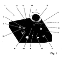
- FIG. 1 is a three-dimensional view of a basic structure of a control element 1 reproduced.
- the control element 1 has a control knob 2, which protrudes at least partially from a housing of the control element 1.
- a central axis 3 is integrally formed or grown, wherein by means of the central axis 4, the light distribution 5 is rotationally connected to the control knob 2.
- a light barrier system formed of a light source 6 and a light receiver 7 is mounted on a printed circuit board 5 held in the housing.
- the light distribution consists in this embodiment of four circular segments representing segments 8, which are held substantially plane-parallel to the circuit board on the light sources 6 and the light receivers 7 in the control element 1 rotatable.
- the segments 8 are held by a disk 9 which extends radially from the central axis 3 and essentially has the task of connecting the segments 8 to a uniform diameter above the light barrier system 6, 7, 8 and above the light source 6 and the light receiver 7 hold and guide.
- the disk 9 can in this case be made of any material, wherein the disk 9 is preferably made of a plastic.
- a cylindrical extension 10 is formed, on the one hand holds the light distribution 4 in position about the central axis and at the same time serves as a storage for the control knob 2.
- the segments 8 in this embodiment have a specifically designed geometry that supports the function of the light barrier system 6, 7, 8, but which represents only a preferred embodiment of the inventive form.
- a cross section through a segment 8, the circuit board 5, the light source 6 and the light receiver 7 is in the FIG. 2 played.
- the segment 8 is formed of two mutually inclined by 45 ° reflection surfaces 11, 12 and a light entrance surface 13 and a light exit surface 14.
- This special geometric cross-sectional shape of the segment 8, on the one hand causes the light L emitted by the light source 6, which is, for example, a light in the infrared region, to be parallelized in the direction of the reflection surface 11 and at the same time serves as a reflection surface 13, which likewise produces a signal in the light barrier system 6, 7, 8 can be generated.
- the parallelized light L is guided by the reflection surface 11 in the direction of the second reflection surface 12, from where it is directed in the direction of the light receiver 7, which is for example a photodiode.
- the light entry surface 13 and the light exit surface 14 are curved, so that they Parallelize light L on the one hand and focus on the other hand, so that a clear evaluation and generation of a signal is possible.
- FIG. 1 illustrated embodiment of the circular segment segments 8 represents only one embodiment. It is also conceivable according to the invention to form the light distribution 4 from a circular disk which is provided with reflection surfaces and the light-absorbing surfaces.
- the embodiment of the light distribution 4 according to the exemplary embodiment offers the advantage that stray radiation on non-reflecting regions of a light distribution does not lead to errors in the evaluation of the signals generated.
- a further advantageous embodiment of the invention is formed in that the reflection surfaces 11, 12 are designed to be coated. If the reflection surfaces 11, 12 coated, for example, painted or mirrored executed, the light pipe is increased in the interior of the segment 8, which in turn leads to an increase in security in the generation of a signal when turning the control knob 2. But it is also conceivable, the segments 8 on its underside 13, 14 perform mirrored, so that the light L is passed directly from the surface 13 in the direction of the light receiver 7. For this purpose, it would of course be easier to form the reflection surfaces 13, 14 of the segment 8 in such a way that the light L is conducted in the direction of the light receiver 7. As the light source 6, for example, a light emitting in the infrared region LED can be used.
- An advantage of the segment shown in the embodiment is that even with a tilting of the control knob 2 about its central axis 3, a signal can be generated.
- the position of the segment 8 in a tilted position is in the FIG. 3 played.
- the position 8 'of the segment 8 indicates the position occupied by the segment 8 when tilted about the central axis 3.
- a signal is generated in the tilted position of the control knob 2 and provided for the electronics for evaluation.
- the in the FIG. 4 shown position of the segment 8 "indicates the position occupied by the segment 8 in a depressed position of the control knob 2. It can be clearly seen that the course of the light L also leads to a generatable signal
- the control knob 2 of the control element 1 is thus executable as a push button, knob and tilting control knob 2, wherein in each position an evaluation of the rotational movement of the Control button 2 is guaranteed.
- a signal is generated, so that a rotation of the control knob 2 can be evaluated at any time about its central axis 3.
- the inventive construction a pulse generator for a control element 1 is provided, which has a high tolerance insensitivity, as by reflection on the reflection surfaces 13 and reflection at the interfaces 11, 12 an evaluation at any time and in any position of the control element 2 is guaranteed.
- the light sources 6 and the light receiver 7 are arranged on a radially extending from the central axis line one behind the other, whereby, upon rotation of the control knob 2 in the direction of arrow P, the light source 6 and the light receiver 7 are simultaneously covered by a segment 8 ,
- a corresponding arrangement of the light source 6 and the light receiver 7 with respect to the segments is by means of two light sources 6 and two light receiver 7, as in the FIG. 1 drawn, a gray code with 16 positions generated, so that on the one hand a direction of rotation and on the other hand, a rotation angle of the control knob 2 can be detected.
- the light distribution 4 is formed in the described embodiment of circle segment sections 8 and free areas 15. This offers the advantage that no scattered radiation falls on the light receiver 7.
- the segment 8 is preferably formed from a transparent and translucent plastic.
- the disc 9 is integrally formed integrally with the segments 8 in this embodiment, and also made of a plastic. However, it is crucial for the function that a material is used which at least supports reflection and reflection at the boundary surfaces (11, 12, 13, 14) and which is suitable for guiding the light.
Landscapes
- Physics & Mathematics (AREA)
- General Physics & Mathematics (AREA)
- Switches With Compound Operations (AREA)
- Mechanical Control Devices (AREA)
- Rotary Switch, Piano Key Switch, And Lever Switch (AREA)
Description
- Die Erfindung betrifft ein Bedienelement für ein Kraftfahrzeug bestehend zumindest aus einem drehbar in einem Gehäuse aufgenommenen Bedienknopf und einem Impulsgeber zur Drehrichtungs- und Drehwinkelerkennung, aufweisend eine verdrehfest mit dem Bedienknopf verbundene Lichtverteilung, zumindest eine Lichtquelle und einen Lichtempfänger, wobei das Licht der Lichtquelle mittels der Lichtverteilung an den Lichtempfänger weiterleitbar ist und die Lichtquelle und der Lichtempfänger ein auswertbares Signal generieren, wobei die Lichtverteilung mindestens einen Bereich ausweist, der zumindest teilweise Reflexion des Lichtes in Richtung des Lichtempfängers bewirkt, wobei die Lichtverteilung eine erste und zweite, um ca. 45° und gegensinnig geneigte Reflexionsfläche aufweist, um das Licht der Lichtquelle über die erste und zweite Reflexionsfläche auf den Lichtempfänger (7) zu leiten.
- Drehbare Bedienelemente in Kraftfahrzeugen sind allgemein bekannt. Eingesetzt werden solche Bedienelemente, zum Beispiel zur Verstellung der Lautstärke eines Rundfunkempfängers, als Drehknöpfe für die Klimaanlage oder das Gebläse oder als zentrales Bedienelement, wobei dem zentralen Bedienelement mehrere Funktionen zuordbar sind. Um die Drehbewegung des Bedienknopfes des Bedienelementes auswerten zu können, sind verschiedenst aufgebaute Bedienelemente bekannt geworden.
- Aus der
WO03/088204A - Eine Möglichkeit die Drehbewegung des Bedienknopfes eines Bedienelementes zu erfassen, ist in der
DE 103 14 315 B4 beschrieben. Mittels einer Lichtverteilung, die verdrehfest am Bedienknopf befestigt ist, ist hierbei eine Kodierung der Drehbewegung mittels einer optoelektronischen Erfassung möglich. Hierbei wird Licht einer Lichtquelle, dass in einen Lichtleiter eingeleitet wird, gleichzeitig in einen Lichtverteiler eingeleitet, wobei sich der Lichtverteiter umfänglich um eine Drehachse des Bedienknopfes speichenförmig erstreckt. Das Licht gelangt somit durch den Lichtleiter in die Lichtverteilung und wird mittels Lichtempfängem empfangen und elektronisch verarbeitet. Durch die Anordnung der Lichtempfänger auf einer unterhalb der Lichtverteilung angeordneten Leiterplatte, ist das Erzeugen eines Gray-Codes möglich, wodurch sowohl Richtung als auch Drehwinkel des Bedienknopfes detektierbar sind. - Aufgabe der Erfindung ist es, ein Bedienelement für ein Kraftfahrzeug bereitzustellen, mittels dem eine Dreh- und Kippbewegung des Bedienknopfes detektierbar ist. Darüber hinaus ist es Aufgabe der Erfindung, ein konstruktiv einfach aufgebautes Bedienelement bereitzustellen, dass darüber hinaus auch kostengünstig zu fertigen ist.
- Die Aufgabe wird erfindungsgemäß dadurch gelöst, dass der Bedienknopf kippbar und.drehbar und optional drückbar gelagert ist und dass die Lichteintrittsfläche und die Lichtaustrittsfläche der Lichtverteilung gewölbt ausgeführt sind, sowie dass sich die erste Reflektionsfläche oberhalb der Lichtquelle und die zweite Reflektionsfläche sich oberhalb des Lichtempfängers befinden und dass das von der Lichtquelle emittierte Licht (L) in Richtung der ersten Reflexionsfläche parallelisiert wird. Durch die erfindungsgemäße Ausbildung des Bedienelementes und insbesondere des Impulsgebers im Bedienelement, ist nun die Möglichkeit geschaffen, ein Bedienelement bereitzustellen, das über den Stand der Technik hinaus in der Lage ist, sowohl drehbar wie auch kippbar ist, eine Drehrichtungs- und Drehwinkelerkennung in jeder Stellung des Bedienknopfes zu gewährleisten. Durch den Aufbau einer Lichtverteilung, die zumindest einen Reflexion hervorrufenden Bereich aufweist und die im einfachsten Fall aus einer dünnen Kunststoffscheibe gebildet ist, ist ein konstruktiv einfaches System bereitgestellt, das darüber hinaus auch wirtschaftlich kostengünstig zu fertigen ist.
- Gleichzeitig besitzt das erfindungsgemäße aufgebaute Bedienelement den Vorteil der Verwendung von infrarotem Licht, so dass einerseits Störeinflüsse aus der Umgehung oder Streustrahlung von Lichtquellen im Bedienelement die Funktionsfähigkeit des Impulsgebers nicht beeinflussen. In einem einfachsten System, wird der Impulsgeber aus einer abschnittsweise reflektierenden Scheibe gebildet, die verdrehfest mit dem Bedienknopf verbunden ist und die mit Bereichen versehen ist, die einerseits eine Reflexion des Lichtes ermöglichen und andererseits Licht absorbieren. So ist eine Scheibe mit kreissegmentartig verspiegelten Oberflächen und in abwechselnder Reihenfolge hierzu lichtabsorbierende, zum Beispiel schwarze Flächen, aufweist vorstellbar, so dass das Kreissegment aus sich abwechselnden Licht spiegelnden und Licht absorbierenden Flächen gebildet ist. Dabei ist die Scheibe planparallel zu einer im Bedienelement angeordneten Leiterplatte in einem Gehäuse des Bedienelementes angeordnet, wobei die das Lichtschrankensystem bildenden Lichtsender und -empfänger unterhalb der Scheibe angeordnet sind. Zur genauen Auswertung der Drehbewegung, ist es hierbei vorstellbar, die Lichtquelle und den Lichtempfänger radial nach außen hintereinander anzuordnen, so dass sie auf einer rechtwinklig zur Drehachse des Bedienelementes gedachten Linie auf der Leiterplatte und parallel zur Scheibe angeordnet sind.
- Vorstellbar ist auch die Scheibe aus Kreisabschnitten, die Segmente bilden und eine Reflexion hervorrufen, auszubilden. Vorstellbar ist hier die Verwendung eines transparenten Kunststoffes, der allein für sich gesehen durch sein Reflexionsvermögen ein Signal im Lichtschrankensystem aus Lichtquelle, Reflexionsfläche und Lichtempfänger zu generieren. In einer vorteilhaften Ausgestaltung der Erfindung, wird darüber hinaus vorgeschlagen in die Lichtverteilung reflektierende Bereiche und das Licht zurückwerfende, leitende Bereiche, so genannte Reflexionsbereiche, einzuarbeiten. Dies erfolgt dadurch, das einerseits ein glassklarer transparenter Kunststoff als Lichtverteilung genommen wird, der allein für sich bereits eine Lichtreflexion hervorruft, und der darüber hinaus mit Lichtleitflächen versehen ist, die das Licht zielgerichtet von der Lichtquelle an eine erste Reflexionsfläche auf eine zweite entgegengesetzt ausgebildete Reflexionsfläche leiten, wodurch das Licht zusätzlich zum reflektierenden Licht zum Lichtempfänger weitergeleitet wird.
- Die Lichtverteilung ist direkt an eine Drehachse des Bedienknopfes des Bedienelementes anspritzbar, oder als separates Teil formschlüssig oder kraftschlüssig an die Drehachse des Bedienknopfs anbaubar.
- Nachfolgend wird die Erfindung anhand eines Ausführungsbeispiels näher erläutert.
- Es zeigt
- Figur 1
- eine dreidimensionale Ansicht auf einen prinzipiellen Aufbau eines Impulsgebers in einem Bedienelement für ein Kraftfahrzeug,
- Figur 2
- den Verlauf des Lichtes in einem Lichtschrankensystem aus Lichtquelle, Lichtverteilung und Lichtempfänger in einer Detailansicht im Schnitt,
- Figur 3
- den Verlauf des Lichtes bei der Betätigung Kippen des Bedienknopfes des Bedienelementes und
- Figur 4
- den Verlauf des Lichtes im Impulsgeber bei der Betätigung Drücken des Bedienknopfes.
- In der
Figur 1 ist eine dreidimensionale Ansicht auf einen prinzipiellen Aufbau eines Bedienelementes 1 wiedergegeben. Das Bedienelement 1 besitzt einen Bedienknopf 2, der zumindest bereichsweise aus einem Gehäuse des Bedienelementes 1 herausragt. An den drehbaren im Gehäuse gelagerten Bedienknopf ist eine Mittelachse 3 angeformt oder angebaut, wobei mittels der Mittelachse 4 die Lichtverteilung 5 verdrehfest mit dem Bedienknopf 2 verbunden ist. Unterhalb der Lichtverteilung 4 ist auf einer im Gehäuse gehaltenen Leiterplatte 5 ein aus einer Lichtquelle 6 und einem Lichtempfänger 7 gebildetes Lichtschrankensystem befestigt. - Die Lichtverteilung besteht in diesem Ausführungsbeispiel aus vier einen Kreisabschnitt darstellenden Segmenten 8, die im Wesentlichen planparallel zur Leiterplatte über den Lichtquellen 6 und den Lichtempfängern 7 im Bedienelement 1 drehbar gehalten sind. Gehalten werden die Segmente 8 von einer sich radial von der Mittelachse 3 aus erstreckenden Scheibe 9, die im Wesentlichen die Aufgabe besitzt, die Segmente 8 auf einem einheitlichen Durchmesser über dem Lichtschrankensystem 6, 7, 8 und oberhalb der Lichtquelle 6 und des Lichtempfängers 7 zu halten und zu führen. Die Scheibe 9 kann hierbei aus einem beliebigen Werkstoff gefertigt sein, wobei die Scheibe 9 bevorzugt aus einem Kunststoff gefertigt ist. An die Scheibe 9 ist eine zylindrische Verlängerung 10 angeformt, die einerseits die Lichtverteilung 4 in ihrer Position um die Mittelachse hält und gleichzeitig als Lagerung für den Bedienknopf 2 dient.
- Die Segmente 8 besitzen in dieser Ausführungsform eine gezielt ausgebildete Geometrie, die die Funktion des Lichtschrankensystems 6, 7, 8 unterstützt, die aber für die erfindungsgemäße Form lediglich ein bevorzugtes Ausführungsbeispiel darstellt. Ein Querschnitt durch ein Segment 8, die Leiterplatte 5, die Lichtquelle 6 und den Lichtempfänger 7 ist in der
Figur 2 wiedergegeben. Das Segment 8 ist aus zwei um 45° zueinander geneigten Reflexionsflächen 11, 12 sowie einer Lichteintrittsfläche 13 und einer Lichtaustrittsfläche 14 gebildet. Diese spezielle geometrische Querschnittsform des Segments 8, bewirkt einerseits, dass das von der Lichtquelle 6, die beispielsweise eine Licht im infraroten Bereich emittierende LED ist, emittierte Licht L in Richtung der Reflexionsfläche 11 parallelisiert wird und dient gleichzeitig als Reflexionsfläche 13, wodurch ebenfalls ein Signal im Lichtschrankensystem 6, 7, 8 generierbar ist. Das parallelisierte Licht L wird von der Reflexionsfläche 11 in Richtung der zweiten Reflexionsfläche 12 geleitet, von wo aus es in Richtung des Lichtempfängers 7, die beispielsweise eine Fotodiode ist, geleitet wird. In diesem Ausführungsbeispiel sind die Lichteintrittsfläche 13 und die Lichtaustrittsfläche 14 gewölbt ausgeführt, so dass sie das Licht L einerseits parallelisieren und andererseits fokussieren, so dass eine eindeutige Auswertung und Generierung eines Signals ermöglicht ist. - Zu beachten bleibt hierbei, dass die in der
Figur 1 dargestellte Ausführungsform der Kreisabschnittssegmente 8 lediglich eine Ausführungsform darstellt. Es ist erfindungsgemäß ebenso vorstellbar, die Lichtverteilung 4 aus einer Kreisscheibe auszubilden, die mit Reflektionsflächen und des Licht absorbierenden Flächen versehen ist. Die Ausbildung der Lichtverteilung 4 gemäß dem Ausführungsbeispiel bietet den Vorteil, dass eine Streustrahlung auf nicht reflektierende Bereiche einer Lichtverteilung nicht zu Fehlern beim Auswerten der erzeugten Signale führt. - Eine weitere vorteilhafte Ausführungsform der Erfindung wird dadurch gebildet, dass die Reflexionsflächen 11, 12 beschichtet ausgeführt sind. Werden die Reflexionsflächen 11, 12 beschichtet, zum Beispiel lackiert oder verspiegelt ausgeführt, so wird die Lichtleitung im Inneren des Segments 8 erhöht, was wiederum zu einer Erhöhung der Sicherheit bei der Generierung eines Signals beim Drehen des Bedienknopfs 2 führt. Es ist aber ebenso vorstellbar, die Segmente 8 an ihrer Unterseite 13, 14 verspiegelt auszuführen, so dass das Licht L unmittelbar von der Fläche 13 in Richtung des Lichtempfängers 7 geleitet wird. Hierzu wäre es selbstverständlich einfacher, die Reflektionsflächen 13, 14 des Segments 8 derart auszuformen, dass das Licht L in Richtung des Lichtempfängers 7 geleitet wird. Als Lichtquelle 6 ist zum Beispiel eine Licht im infraroten Bereich emittierende LED einsetzbar.
- Vorteilhaft bei dem in dem Ausführungsbeispiel dargestellten Segment ist, dass auch bei einem Kippen des Bedienknopfes 2 um seine Mittelachse 3 ein Signal generierbar ist. Die Stellung des Segmentes 8 in einer gekippten Position ist in der
Figur 3 wiedergegeben. Dabei zeigt die Stellung 8' des Segmentes 8 die Stellung an, die das Segment 8 bei einem Kippen um die Mittelachse 3 einnimmt. Wie deutlich am eingezeichneten Verlauf des Lichtes L von der Lichtquelle 6 durch das Segment 8' zum Lichtempfänger 7 zu erkennen, wird auch in der gekippten Stellung des Bedienknopfes 2 ein Signal generiert und für die Elektronik zur Auswertung bereitgestellt. - Die in der
Figur 4 dargestellte Position des Segmentes 8" zeigt die Position an, die das Segment 8 bei einer gedrückten Stellung des Bedienknopfes 2 einnimmt. Es ist deutlich zu erkennen, dass der Verlauf des Lichtes L ebenfalls zu einem generierbaren Signal führt. Der Bedienknopf 2 des Bedienelementes 1 ist somit als Druckknopf, Drehknopf und kippbarer Bedienknopf 2 ausführbar, wobei in jeder Position eine Auswertung der Drehbewegung des Bedienknopfes 2 gewährleistet bleibt. In jeder Position des Bedienknopfes 2, wie sie in denFiguren 2, 3 und 4 dargestellt sind, wird ein Signal generiert, so dass ein Drehen des Bedienknopfs 2 um seine Mittelachse 3 jederzeit auswertbar ist. Durch den erfindungsgemäßen Aufbau ist ein Impulsgeber für ein Bedienelement 1 bereitgestellt, der eine hohe Toleranzunempfindlichkeit aufweist, da durch Reflektion auf den Reflektionsflächen 13 und Reflexion an den Grenzflächen 11, 12 eine Auswertung zu jedem Zeitpunkt und in jeder Stellung des Bedienelementes 2 gewährleistet ist. - Wie in der
Figur 1 ersichtlich, sind die Lichtquellen 6 und die Lichtempfänger 7 auf einer sich radial von der Mittelachse erstreckenden Linie hintereinander angeordnet, wodurch, bei einem Verdrehen des Bedienknopfs 2 in Richtung des Pfeils P, die Lichtquelle 6 und der Lichtempfänger 7 gleichzeitig von einem Segment 8 überdeckt werden. Durch eine entsprechende Anordnung der Lichtquelle 6 und des Lichtempfängers 7 in Bezug auf die Segmente ist mittels zweier Lichtquellen 6 und zweier Lichtempfänger 7, wie in derFigur 1 eingezeichnet, ein Gray-Code mit 16 Positionen erzeugbar, so dass einerseits eines Drehrichtung und andererseits ein Drehwinkel des Bedienknopfes 2 detektierbar ist. Auf eine entsprechende Auswertung des Gray-Codes wird auf die Offenbarung derDE 103 14 315 B4 Bezug genommen, wobei ausdrücklich darauf hingewiesen wird, dass deren Offenbarungsgehalt auf die Erfindung anwendbar ist. So ist es insbesondere natürlich vorstellbar, mehr als in dem Ausführungsbeispiel gezeigte Lichtschrankensysteme 6, 7, 8 am Umfang des Bedienknopfes 2 und der Lichtverteilung 4 anzuordnen, um somit zum Beispiel auch die absolute Position des Bedienknopfes 2 zu detektieren. - Die Lichtverteilung 4 wird in dem beschriebenen Ausführungsbeispiel aus Kreissegmentabschnitten 8 und freien Bereichen 15 gebildet. Dies bietet den Vorteil, dass keine Streustrahlung auf den Lichtempfänger 7 fällt. Das Segment 8 wird hierbei bevorzugt aus einem transparenten und transluzenten Kunststoff gebildet. Die Scheibe 9 ist in diesem Ausführungsbeispiel einstöckig an die Segmente 8 angeformt, und ebenfalls aus einem Kunststoff herstellbar. Für die Funktion ist aber entscheidend, dass ein Werkstoff verwendet wird, der eine Reflektion und Reflexion an den Grenzflächen (11, 12, 13, 14) zumindest unterstützt und der sich für ein Leiten des Lichtes eignet.
Claims (11)
- Bedienelement (1) für ein Kraftfahrzeug, bestehend zumindest aus einem drehbar in einem Gehäuse aufgenommenen Bedienknopf (2) und einem Impulsgeber zur Drehrichtungs- und Drehwinkelerkennung, aufweisend eine verdrehfest mit dem Bedienknopf (2) verbundene Lichtverteilung (4), zumindest eine Lichtquelle (6) und einen Lichtempfänger (7), wobei das Licht (L) der Lichtquelle (6) mittels der Lichtverteilung (4) an den Lichtempfänger (7) weiterleitbar ist und Lichtquelle (6) und Lichtempfänger (7) ein auswertbares Signal generieren, wobei die Lichtverteilung (4) mindestens einen Bereich ausweist, der zumindest teilweise Reflexion (13, 14) des Lichtes (L) in Richtung des Lichtempfängers (7) bewirkt, wobei die Lichtverteilung (4) eine erste und zweite, um ca. 45° und gegensinnig geneigte Reflexionsfläche (11, 12) aufweist, um das Licht (L) der Lichtquelle (6) über die erste und zweite Reflexionsfläche (11, 12) auf den Lichtempfänger (7) zu leiten, wobei der Bedienknopf kippbar und drehbar und optional drückbar gelagert ist, dadurch gekennzeichnet, dass die Lichteintrittsfläche (13) und die Lichtaustrittsfläche (14) der Lichtverteilung (4) gewölbt ausgeführt sind, sowie dass sich die erste Reflexionsfläche (11) oberhalb der Lichtquelle (6) und die zweite Reflexionsfläche (12) sich oberhalb des Lichtempfängers (7) befinden und dass das von der Lichtquelle (6) emittierte Licht (L) in Richtung der ersten Reflexionsfläche (11) parallelisiert wird.
- Bedienelement (1) nach Anspruch 1, dadurch gekennzeichnet, dass die Lichtquelle (6) Licht (L) im infraroten Bereich emittert
- Bedienelement (1) nach Anspruch 1 und 2, dadurch gekennzeichnet, dass die Lichtverteilung (4) umfänglich um eine Drehachse (3) des Bedienknopfes (2) im Bedienelement (1) angeordnet ist.
- Bedienelement (1) nach Patentanspruch 1 bis 3, dadurch gekennzeichnet, dass die Lichtquelle (6) und der Lichtempfänger (7) auf einer im Gehäuse befestigten Leiterplatte (5) befestigt sind.
- Bedienelement (1) nach Patentanspruch 4, dadurch gekennzeichnet, dass die Lichtquelle (6) und der Lichtempfänger (7) unterhalb der Lichtverteilung (4) auf der Leiterplatte (5) befestigt sind.
- Bedienelement (1) nach Patentanspruch 4 und 5, dadurch gekennzeichnet, dass die Lichtverteilung (4) sich im Wesentlichen rechtwinklig zur Drehachse (3) und planparallel über die Leiterplatte (5) hinweg erstreckt.
- Bedienelement (1) nach einem der Ansprüche 1 bis 6, dadurch gekennzeichnet, dass die Lichtverteilung (4) aus mindestens einem einen Kreisabschnitt bildenden Segment (8) gebildet ist.
- Bedienelement (1) nach Patentanspruch 7, dadurch gekennzeichnet, dass die Lichtverteilung (4) aus vier Kreisabschnittssegmenten (8) gebildet ist, so dass die Lichtverteilung (4) die Form eines Speichenrades mit vier Speichen aufweist.
- Bedienelement (1) nach einem der Ansprüche 1 bis 8, dadurch gekennzeichnet, dass die Lichtverteilung (4) aus einem transparenten Kunststoff gebildet ist.
- Bedienelement (1) nach einem des Ansprüche 1 bis 9, dadurch gekennzeichnet, dass die Lichtverteilung (4) beschichtet ist, wobei die Beschichtung aus einer verspiegelten Fläche oder einem weißen oder silbernen Lack gebildet ist.
- Bedienelement (1) nach Patentanspruch 10, dadurch gekennzeichnet, dass die Lichtverteilung (4) oberhalb der Reflexionsflächen (11, 12) beschichtet ist.
Applications Claiming Priority (2)
| Application Number | Priority Date | Filing Date | Title |
|---|---|---|---|
| DE102006047471A DE102006047471B4 (de) | 2006-10-05 | 2006-10-05 | Impulsgeber für ein Bedienelement in einem Kraftfahrzeug |
| PCT/EP2007/008350 WO2008040473A1 (de) | 2006-10-05 | 2007-09-26 | Impulsgeber für ein bedienelement in einem kraftfahrzeug |
Publications (2)
| Publication Number | Publication Date |
|---|---|
| EP2076737A1 EP2076737A1 (de) | 2009-07-08 |
| EP2076737B1 true EP2076737B1 (de) | 2012-01-25 |
Family
ID=38754478
Family Applications (1)
| Application Number | Title | Priority Date | Filing Date |
|---|---|---|---|
| EP07818434A Not-in-force EP2076737B1 (de) | 2006-10-05 | 2007-09-26 | Bedienelement für ein kraftfahrzeug mit einem impulsgeber |
Country Status (4)
| Country | Link |
|---|---|
| EP (1) | EP2076737B1 (de) |
| AT (1) | ATE543076T1 (de) |
| DE (1) | DE102006047471B4 (de) |
| WO (1) | WO2008040473A1 (de) |
Families Citing this family (9)
| Publication number | Priority date | Publication date | Assignee | Title |
|---|---|---|---|---|
| EP2213987A1 (de) | 2009-02-03 | 2010-08-04 | Leica Geosystems AG | Optoelektronische Lagemesseinrichtung und optoelektronisches Lagemessverfahren |
| DE102009025595A1 (de) * | 2009-06-19 | 2010-12-23 | Brendel, Wolfgang, Dipl.-Ing. | Elektro-optischer Signalgeber |
| FR2954491B1 (fr) * | 2009-12-23 | 2012-04-27 | Thales Sa | Codeur optique. |
| EP2730894B1 (de) | 2012-11-13 | 2019-03-13 | Itron GmbH | Detektor, Lichtleiter und Zählereinrichtung |
| ES2530544B1 (es) * | 2013-09-03 | 2015-12-15 | Bsh Electrodomésticos España, S.A. | Disposición de mando para aparato doméstico, y aparato doméstico |
| JP5792253B2 (ja) * | 2013-10-02 | 2015-10-07 | ファナック株式会社 | 導光路を有する透過型光学式エンコーダ |
| DE102014223348A1 (de) * | 2014-11-17 | 2016-05-19 | Zf Friedrichshafen Ag | Vorrichtung und Verfahren zum Bestimmen einer Position eines Bewegungselements und mechanisches System |
| CN108334156A (zh) * | 2018-02-26 | 2018-07-27 | 广州医仕博体育科技有限公司 | 一种旋钮组件及判断旋钮旋转方向的方法 |
| CN112325912A (zh) * | 2020-11-20 | 2021-02-05 | 广东瑞讯电子科技有限公司 | 光学编码器组件 |
Family Cites Families (15)
| Publication number | Priority date | Publication date | Assignee | Title |
|---|---|---|---|---|
| SE367868B (de) * | 1972-10-26 | 1974-06-10 | Ericsson Telefon Ab L M | |
| US4820918A (en) * | 1985-06-28 | 1989-04-11 | Canon Kabushiki Kaisha | Optical encoder including transparent substrates having formed indicators therein |
| DD273890A1 (de) * | 1988-07-11 | 1989-11-29 | Zeiss Jena Veb Carl | Anordnung zur signalerzeugung fuer die messung der winkellage eines kippbaren spiegels |
| FR2666145B1 (fr) * | 1990-08-27 | 1994-05-20 | Jaeger | Perfectionnements aux capteurs optiques. |
| DE4336729C2 (de) * | 1993-10-28 | 2003-04-24 | Marquardt Gmbh | Optischer Schalter |
| JP3483234B2 (ja) * | 1996-10-24 | 2004-01-06 | シャープ株式会社 | 光学式センサ |
| NO305048B1 (no) * | 1997-08-18 | 1999-03-22 | Steinar Pedersen | Redskap for styring av PC-mark°r med ekstra styringsmodus i randsonen |
| DE29817668U1 (de) * | 1997-10-31 | 1999-01-07 | Leopold Kostal GmbH & Co. KG, 58507 Lüdenscheid | Vorrichtung zum Erfassen von Schaltstellungen eines mechanisch betätigbaren Schaltmittels |
| US6195083B1 (en) * | 1997-11-14 | 2001-02-27 | Septimiu E. Salcudean | Active joystick with optical positions sensor |
| AU2003224982A1 (en) * | 2002-04-12 | 2003-10-27 | Fritz H. Obermeyer | Multi-axis joystick and transducer means therefore |
| DE10227803B4 (de) * | 2002-06-21 | 2013-09-26 | Continental Automotive Gmbh | Bedienelement für Kraftfahrzeugkomponenten |
| DE60204775T2 (de) * | 2002-08-28 | 2005-12-01 | Siemens Ag | Eingabevorrichtung und Eingabeverfahren |
| WO2004059346A2 (en) * | 2002-12-16 | 2004-07-15 | Microe Systems Corp. | Rotary position sensor with offset beam generating element and elliptical detector array |
| DE10314315B4 (de) * | 2003-03-29 | 2006-03-30 | Preh Gmbh | Bedienelement |
| FR2861212B1 (fr) * | 2003-10-20 | 2006-03-03 | Valeo Climatisation | Tableau de commande pour planche de bord de vehicule automobile muni d'au moins un bouton rotatif de reglage a commande optique. |
-
2006
- 2006-10-05 DE DE102006047471A patent/DE102006047471B4/de not_active Expired - Fee Related
-
2007
- 2007-09-26 EP EP07818434A patent/EP2076737B1/de not_active Not-in-force
- 2007-09-26 WO PCT/EP2007/008350 patent/WO2008040473A1/de not_active Ceased
- 2007-09-26 AT AT07818434T patent/ATE543076T1/de active
Also Published As
| Publication number | Publication date |
|---|---|
| WO2008040473A1 (de) | 2008-04-10 |
| EP2076737A1 (de) | 2009-07-08 |
| DE102006047471A1 (de) | 2008-04-10 |
| ATE543076T1 (de) | 2012-02-15 |
| DE102006047471B4 (de) | 2009-05-28 |
Similar Documents
| Publication | Publication Date | Title |
|---|---|---|
| WO2008040473A1 (de) | Impulsgeber für ein bedienelement in einem kraftfahrzeug | |
| DE102013208649B4 (de) | Optischer Winkeldetektor mit Strahlformungselement | |
| EP2860497B2 (de) | Optoelektronischer Sensor und Verfahren zur Herstellung eines solchen | |
| DE19835972C1 (de) | Optoelektronische Positionserfassungseinrichtung zur absoluten Weg- oder Winkelbestimmung sowie Verwendung einer solchen Einrichtung | |
| DE102015118258B3 (de) | Laserscanner und Verfahren zur Überprüfung von dessen Funktionsfähigkeit | |
| EP1999533B1 (de) | Bedienelement mit einer kipphaptik für ein kraftfahrzeug | |
| EP0958493B1 (de) | Optische sende- und empfangseinrichtung | |
| DE102017117162A1 (de) | Sensor und Verfahren zur Erfassung und Abstandsbestimmung von Objekten | |
| DE102018110566A1 (de) | Verfahren zur Überprüfung der Funktionsfähigkeit eines Laserscanners und Laserscanner | |
| WO2018014926A1 (de) | Drehbetätigungsvorrichtung | |
| WO2017001112A1 (de) | Optische sensorvorrichtung mit zusätzlicher kapazitiver sensorik | |
| WO2005027352A1 (de) | Integrierter optischer encoder | |
| DE10325108A1 (de) | Optoelektronischer Drehwinkelsensor | |
| DE102015116957A1 (de) | Vorrichtung zur Erfassung der absoluten Position eines Drehknopfes | |
| DE102016101024B4 (de) | Bedienelement mit verbesserter Fehlfunktionsdetektion | |
| DE102008004047B4 (de) | Absolut messender optischer Drehwinkelsensor | |
| DE102005027087A1 (de) | Beschlagsensor für ein Kraftfahrzeug | |
| EP1740910B1 (de) | Drehsteller | |
| DE102019003586A1 (de) | Detektionsvorrichtung für einen absoluten Drehwinkel bei Mehrfachdrehung und Zahnrad | |
| DE112022001553T5 (de) | Vorrichtung und verfahren zur erfassung von bewegungen entlang einer achse | |
| DE212013000245U1 (de) | Optischer Winkeldetektor | |
| DE19918313A1 (de) | Winkelsensor | |
| DE202006005876U1 (de) | Optischer Sensor | |
| WO2005103857A1 (de) | Bedienelement für ein kraftfahrzeug | |
| DE102007055497A1 (de) | Optischer Sensor für ein Kraftfahrzeug |
Legal Events
| Date | Code | Title | Description |
|---|---|---|---|
| PUAI | Public reference made under article 153(3) epc to a published international application that has entered the european phase |
Free format text: ORIGINAL CODE: 0009012 |
|
| 17P | Request for examination filed |
Effective date: 20090506 |
|
| AK | Designated contracting states |
Kind code of ref document: A1 Designated state(s): AT BE BG CH CY CZ DE DK EE ES FI FR GB GR HU IE IS IT LI LT LU LV MC MT NL PL PT RO SE SI SK TR |
|
| 17Q | First examination report despatched |
Effective date: 20100108 |
|
| RTI1 | Title (correction) |
Free format text: OPERATING ELEMENT FOR A VEHICLE COMPRISING A PULSE GENERATOR |
|
| GRAP | Despatch of communication of intention to grant a patent |
Free format text: ORIGINAL CODE: EPIDOSNIGR1 |
|
| GRAS | Grant fee paid |
Free format text: ORIGINAL CODE: EPIDOSNIGR3 |
|
| GRAA | (expected) grant |
Free format text: ORIGINAL CODE: 0009210 |
|
| DAX | Request for extension of the european patent (deleted) | ||
| AK | Designated contracting states |
Kind code of ref document: B1 Designated state(s): AT BE BG CH CY CZ DE DK EE ES FI FR GB GR HU IE IS IT LI LT LU LV MC MT NL PL PT RO SE SI SK TR |
|
| REG | Reference to a national code |
Ref country code: GB Ref legal event code: FG4D Free format text: NOT ENGLISH |
|
| REG | Reference to a national code |
Ref country code: CH Ref legal event code: EP |
|
| REG | Reference to a national code |
Ref country code: AT Ref legal event code: REF Ref document number: 543076 Country of ref document: AT Kind code of ref document: T Effective date: 20120215 |
|
| REG | Reference to a national code |
Ref country code: IE Ref legal event code: FG4D |
|
| REG | Reference to a national code |
Ref country code: DE Ref legal event code: R096 Ref document number: 502007009172 Country of ref document: DE Effective date: 20120322 |
|
| REG | Reference to a national code |
Ref country code: NL Ref legal event code: VDEP Effective date: 20120125 |
|
| LTIE | Lt: invalidation of european patent or patent extension |
Effective date: 20120125 |
|
| PG25 | Lapsed in a contracting state [announced via postgrant information from national office to epo] |
Ref country code: LT Free format text: LAPSE BECAUSE OF FAILURE TO SUBMIT A TRANSLATION OF THE DESCRIPTION OR TO PAY THE FEE WITHIN THE PRESCRIBED TIME-LIMIT Effective date: 20120125 Ref country code: BG Free format text: LAPSE BECAUSE OF FAILURE TO SUBMIT A TRANSLATION OF THE DESCRIPTION OR TO PAY THE FEE WITHIN THE PRESCRIBED TIME-LIMIT Effective date: 20120425 Ref country code: IS Free format text: LAPSE BECAUSE OF FAILURE TO SUBMIT A TRANSLATION OF THE DESCRIPTION OR TO PAY THE FEE WITHIN THE PRESCRIBED TIME-LIMIT Effective date: 20120525 Ref country code: NL Free format text: LAPSE BECAUSE OF FAILURE TO SUBMIT A TRANSLATION OF THE DESCRIPTION OR TO PAY THE FEE WITHIN THE PRESCRIBED TIME-LIMIT Effective date: 20120125 |
|
| REG | Reference to a national code |
Ref country code: IE Ref legal event code: FD4D |
|
| PG25 | Lapsed in a contracting state [announced via postgrant information from national office to epo] |
Ref country code: LV Free format text: LAPSE BECAUSE OF FAILURE TO SUBMIT A TRANSLATION OF THE DESCRIPTION OR TO PAY THE FEE WITHIN THE PRESCRIBED TIME-LIMIT Effective date: 20120125 Ref country code: GR Free format text: LAPSE BECAUSE OF FAILURE TO SUBMIT A TRANSLATION OF THE DESCRIPTION OR TO PAY THE FEE WITHIN THE PRESCRIBED TIME-LIMIT Effective date: 20120426 Ref country code: PT Free format text: LAPSE BECAUSE OF FAILURE TO SUBMIT A TRANSLATION OF THE DESCRIPTION OR TO PAY THE FEE WITHIN THE PRESCRIBED TIME-LIMIT Effective date: 20120525 Ref country code: FI Free format text: LAPSE BECAUSE OF FAILURE TO SUBMIT A TRANSLATION OF THE DESCRIPTION OR TO PAY THE FEE WITHIN THE PRESCRIBED TIME-LIMIT Effective date: 20120125 Ref country code: PL Free format text: LAPSE BECAUSE OF FAILURE TO SUBMIT A TRANSLATION OF THE DESCRIPTION OR TO PAY THE FEE WITHIN THE PRESCRIBED TIME-LIMIT Effective date: 20120125 |
|
| PG25 | Lapsed in a contracting state [announced via postgrant information from national office to epo] |
Ref country code: CY Free format text: LAPSE BECAUSE OF FAILURE TO SUBMIT A TRANSLATION OF THE DESCRIPTION OR TO PAY THE FEE WITHIN THE PRESCRIBED TIME-LIMIT Effective date: 20120125 |
|
| PG25 | Lapsed in a contracting state [announced via postgrant information from national office to epo] |
Ref country code: SI Free format text: LAPSE BECAUSE OF FAILURE TO SUBMIT A TRANSLATION OF THE DESCRIPTION OR TO PAY THE FEE WITHIN THE PRESCRIBED TIME-LIMIT Effective date: 20120125 Ref country code: SE Free format text: LAPSE BECAUSE OF FAILURE TO SUBMIT A TRANSLATION OF THE DESCRIPTION OR TO PAY THE FEE WITHIN THE PRESCRIBED TIME-LIMIT Effective date: 20120125 Ref country code: RO Free format text: LAPSE BECAUSE OF FAILURE TO SUBMIT A TRANSLATION OF THE DESCRIPTION OR TO PAY THE FEE WITHIN THE PRESCRIBED TIME-LIMIT Effective date: 20120125 Ref country code: IE Free format text: LAPSE BECAUSE OF FAILURE TO SUBMIT A TRANSLATION OF THE DESCRIPTION OR TO PAY THE FEE WITHIN THE PRESCRIBED TIME-LIMIT Effective date: 20120125 Ref country code: EE Free format text: LAPSE BECAUSE OF FAILURE TO SUBMIT A TRANSLATION OF THE DESCRIPTION OR TO PAY THE FEE WITHIN THE PRESCRIBED TIME-LIMIT Effective date: 20120125 Ref country code: DK Free format text: LAPSE BECAUSE OF FAILURE TO SUBMIT A TRANSLATION OF THE DESCRIPTION OR TO PAY THE FEE WITHIN THE PRESCRIBED TIME-LIMIT Effective date: 20120125 Ref country code: CZ Free format text: LAPSE BECAUSE OF FAILURE TO SUBMIT A TRANSLATION OF THE DESCRIPTION OR TO PAY THE FEE WITHIN THE PRESCRIBED TIME-LIMIT Effective date: 20120125 |
|
| PG25 | Lapsed in a contracting state [announced via postgrant information from national office to epo] |
Ref country code: SK Free format text: LAPSE BECAUSE OF FAILURE TO SUBMIT A TRANSLATION OF THE DESCRIPTION OR TO PAY THE FEE WITHIN THE PRESCRIBED TIME-LIMIT Effective date: 20120125 Ref country code: IT Free format text: LAPSE BECAUSE OF FAILURE TO SUBMIT A TRANSLATION OF THE DESCRIPTION OR TO PAY THE FEE WITHIN THE PRESCRIBED TIME-LIMIT Effective date: 20120125 |
|
| PLBE | No opposition filed within time limit |
Free format text: ORIGINAL CODE: 0009261 |
|
| STAA | Information on the status of an ep patent application or granted ep patent |
Free format text: STATUS: NO OPPOSITION FILED WITHIN TIME LIMIT |
|
| 26N | No opposition filed |
Effective date: 20121026 |
|
| REG | Reference to a national code |
Ref country code: DE Ref legal event code: R097 Ref document number: 502007009172 Country of ref document: DE Effective date: 20121026 |
|
| BERE | Be: lapsed |
Owner name: PREH G.M.B.H. Effective date: 20120930 |
|
| PG25 | Lapsed in a contracting state [announced via postgrant information from national office to epo] |
Ref country code: ES Free format text: LAPSE BECAUSE OF FAILURE TO SUBMIT A TRANSLATION OF THE DESCRIPTION OR TO PAY THE FEE WITHIN THE PRESCRIBED TIME-LIMIT Effective date: 20120506 Ref country code: MC Free format text: LAPSE BECAUSE OF NON-PAYMENT OF DUE FEES Effective date: 20120930 |
|
| REG | Reference to a national code |
Ref country code: CH Ref legal event code: PL |
|
| GBPC | Gb: european patent ceased through non-payment of renewal fee |
Effective date: 20120926 |
|
| REG | Reference to a national code |
Ref country code: FR Ref legal event code: ST Effective date: 20130531 |
|
| PG25 | Lapsed in a contracting state [announced via postgrant information from national office to epo] |
Ref country code: CH Free format text: LAPSE BECAUSE OF NON-PAYMENT OF DUE FEES Effective date: 20120930 Ref country code: BE Free format text: LAPSE BECAUSE OF NON-PAYMENT OF DUE FEES Effective date: 20120930 Ref country code: LI Free format text: LAPSE BECAUSE OF NON-PAYMENT OF DUE FEES Effective date: 20120930 Ref country code: GB Free format text: LAPSE BECAUSE OF NON-PAYMENT OF DUE FEES Effective date: 20120926 |
|
| PG25 | Lapsed in a contracting state [announced via postgrant information from national office to epo] |
Ref country code: FR Free format text: LAPSE BECAUSE OF NON-PAYMENT OF DUE FEES Effective date: 20121001 |
|
| REG | Reference to a national code |
Ref country code: AT Ref legal event code: MM01 Ref document number: 543076 Country of ref document: AT Kind code of ref document: T Effective date: 20120926 |
|
| PG25 | Lapsed in a contracting state [announced via postgrant information from national office to epo] |
Ref country code: MT Free format text: LAPSE BECAUSE OF FAILURE TO SUBMIT A TRANSLATION OF THE DESCRIPTION OR TO PAY THE FEE WITHIN THE PRESCRIBED TIME-LIMIT Effective date: 20120125 |
|
| PG25 | Lapsed in a contracting state [announced via postgrant information from national office to epo] |
Ref country code: AT Free format text: LAPSE BECAUSE OF NON-PAYMENT OF DUE FEES Effective date: 20120926 |
|
| PG25 | Lapsed in a contracting state [announced via postgrant information from national office to epo] |
Ref country code: TR Free format text: LAPSE BECAUSE OF FAILURE TO SUBMIT A TRANSLATION OF THE DESCRIPTION OR TO PAY THE FEE WITHIN THE PRESCRIBED TIME-LIMIT Effective date: 20120125 |
|
| PG25 | Lapsed in a contracting state [announced via postgrant information from national office to epo] |
Ref country code: LU Free format text: LAPSE BECAUSE OF NON-PAYMENT OF DUE FEES Effective date: 20120926 |
|
| PG25 | Lapsed in a contracting state [announced via postgrant information from national office to epo] |
Ref country code: HU Free format text: LAPSE BECAUSE OF FAILURE TO SUBMIT A TRANSLATION OF THE DESCRIPTION OR TO PAY THE FEE WITHIN THE PRESCRIBED TIME-LIMIT Effective date: 20070926 |
|
| REG | Reference to a national code |
Ref country code: DE Ref legal event code: R082 Ref document number: 502007009172 Country of ref document: DE Representative=s name: LOHMANNS, BERNARD, DIPL.-PHYS., DE |
|
| PGFP | Annual fee paid to national office [announced via postgrant information from national office to epo] |
Ref country code: DE Payment date: 20230919 Year of fee payment: 17 |
|
| REG | Reference to a national code |
Ref country code: DE Ref legal event code: R119 Ref document number: 502007009172 Country of ref document: DE |
|
| PG25 | Lapsed in a contracting state [announced via postgrant information from national office to epo] |
Ref country code: DE Free format text: LAPSE BECAUSE OF NON-PAYMENT OF DUE FEES Effective date: 20250401 |