EP2075426A1 - Ajustement glissant et dispositif de traitement des gaz d'échappement - Google Patents
Ajustement glissant et dispositif de traitement des gaz d'échappement Download PDFInfo
- Publication number
- EP2075426A1 EP2075426A1 EP08171414A EP08171414A EP2075426A1 EP 2075426 A1 EP2075426 A1 EP 2075426A1 EP 08171414 A EP08171414 A EP 08171414A EP 08171414 A EP08171414 A EP 08171414A EP 2075426 A1 EP2075426 A1 EP 2075426A1
- Authority
- EP
- European Patent Office
- Prior art keywords
- tube
- component
- housing
- sliding seat
- bearing material
- Prior art date
- Legal status (The legal status is an assumption and is not a legal conclusion. Google has not performed a legal analysis and makes no representation as to the accuracy of the status listed.)
- Granted
Links
- 239000000463 material Substances 0.000 claims abstract description 41
- 239000000835 fiber Substances 0.000 claims abstract description 30
- 238000002485 combustion reaction Methods 0.000 claims abstract description 7
- 239000003365 glass fiber Substances 0.000 claims abstract description 5
- KZHJGOXRZJKJNY-UHFFFAOYSA-N dioxosilane;oxo(oxoalumanyloxy)alumane Chemical compound O=[Si]=O.O=[Si]=O.O=[Al]O[Al]=O.O=[Al]O[Al]=O.O=[Al]O[Al]=O KZHJGOXRZJKJNY-UHFFFAOYSA-N 0.000 claims abstract description 3
- 229910052863 mullite Inorganic materials 0.000 claims abstract description 3
- TWNQGVIAIRXVLR-UHFFFAOYSA-N oxo(oxoalumanyloxy)alumane Chemical compound O=[Al]O[Al]=O TWNQGVIAIRXVLR-UHFFFAOYSA-N 0.000 claims abstract 2
- 239000004744 fabric Substances 0.000 claims description 18
- 239000003054 catalyst Substances 0.000 claims description 11
- 239000011324 bead Substances 0.000 claims description 4
- 238000002156 mixing Methods 0.000 claims description 3
- 239000000919 ceramic Substances 0.000 claims description 2
- 239000007788 liquid Substances 0.000 claims description 2
- 230000003647 oxidation Effects 0.000 claims description 2
- 238000007254 oxidation reaction Methods 0.000 claims description 2
- 239000000376 reactant Substances 0.000 claims description 2
- 239000007789 gas Substances 0.000 description 25
- QGZKDVFQNNGYKY-UHFFFAOYSA-N Ammonia Chemical compound N QGZKDVFQNNGYKY-UHFFFAOYSA-N 0.000 description 8
- 229910021529 ammonia Inorganic materials 0.000 description 4
- 239000002245 particle Substances 0.000 description 4
- 238000007789 sealing Methods 0.000 description 4
- XSQUKJJJFZCRTK-UHFFFAOYSA-N Urea Chemical compound NC(N)=O XSQUKJJJFZCRTK-UHFFFAOYSA-N 0.000 description 3
- 239000004202 carbamide Substances 0.000 description 3
- 230000003197 catalytic effect Effects 0.000 description 3
- 230000000694 effects Effects 0.000 description 3
- 238000002347 injection Methods 0.000 description 3
- 239000007924 injection Substances 0.000 description 3
- MWUXSHHQAYIFBG-UHFFFAOYSA-N nitrogen oxide Inorganic materials O=[N] MWUXSHHQAYIFBG-UHFFFAOYSA-N 0.000 description 3
- 230000003584 silencer Effects 0.000 description 3
- 238000011144 upstream manufacturing Methods 0.000 description 3
- IJGRMHOSHXDMSA-UHFFFAOYSA-N Atomic nitrogen Chemical compound N#N IJGRMHOSHXDMSA-UHFFFAOYSA-N 0.000 description 2
- 230000001419 dependent effect Effects 0.000 description 2
- 238000006460 hydrolysis reaction Methods 0.000 description 2
- PNEYBMLMFCGWSK-UHFFFAOYSA-N aluminium oxide Inorganic materials [O-2].[O-2].[O-2].[Al+3].[Al+3] PNEYBMLMFCGWSK-UHFFFAOYSA-N 0.000 description 1
- 238000010531 catalytic reduction reaction Methods 0.000 description 1
- 238000006243 chemical reaction Methods 0.000 description 1
- 239000011248 coating agent Substances 0.000 description 1
- 238000000576 coating method Methods 0.000 description 1
- 238000010276 construction Methods 0.000 description 1
- 238000001816 cooling Methods 0.000 description 1
- 238000005516 engineering process Methods 0.000 description 1
- 230000007613 environmental effect Effects 0.000 description 1
- 239000003344 environmental pollutant Substances 0.000 description 1
- 238000007667 floating Methods 0.000 description 1
- 239000012530 fluid Substances 0.000 description 1
- 238000010438 heat treatment Methods 0.000 description 1
- 230000007062 hydrolysis Effects 0.000 description 1
- 238000002955 isolation Methods 0.000 description 1
- 239000000314 lubricant Substances 0.000 description 1
- 229910052757 nitrogen Inorganic materials 0.000 description 1
- 231100000719 pollutant Toxicity 0.000 description 1
- 238000006722 reduction reaction Methods 0.000 description 1
- 239000000243 solution Substances 0.000 description 1
- 230000035882 stress Effects 0.000 description 1
- 230000008646 thermal stress Effects 0.000 description 1
Images


Classifications
-
- F—MECHANICAL ENGINEERING; LIGHTING; HEATING; WEAPONS; BLASTING
- F01—MACHINES OR ENGINES IN GENERAL; ENGINE PLANTS IN GENERAL; STEAM ENGINES
- F01N—GAS-FLOW SILENCERS OR EXHAUST APPARATUS FOR MACHINES OR ENGINES IN GENERAL; GAS-FLOW SILENCERS OR EXHAUST APPARATUS FOR INTERNAL COMBUSTION ENGINES
- F01N13/00—Exhaust or silencing apparatus characterised by constructional features ; Exhaust or silencing apparatus, or parts thereof, having pertinent characteristics not provided for in, or of interest apart from, groups F01N1/00 - F01N5/00, F01N9/00, F01N11/00
- F01N13/16—Selection of particular materials
-
- F—MECHANICAL ENGINEERING; LIGHTING; HEATING; WEAPONS; BLASTING
- F01—MACHINES OR ENGINES IN GENERAL; ENGINE PLANTS IN GENERAL; STEAM ENGINES
- F01N—GAS-FLOW SILENCERS OR EXHAUST APPARATUS FOR MACHINES OR ENGINES IN GENERAL; GAS-FLOW SILENCERS OR EXHAUST APPARATUS FOR INTERNAL COMBUSTION ENGINES
- F01N1/00—Silencing apparatus characterised by method of silencing
- F01N1/08—Silencing apparatus characterised by method of silencing by reducing exhaust energy by throttling or whirling
- F01N1/084—Silencing apparatus characterised by method of silencing by reducing exhaust energy by throttling or whirling the gases flowing through the silencer two or more times longitudinally in opposite directions, e.g. using parallel or concentric tubes
-
- F—MECHANICAL ENGINEERING; LIGHTING; HEATING; WEAPONS; BLASTING
- F01—MACHINES OR ENGINES IN GENERAL; ENGINE PLANTS IN GENERAL; STEAM ENGINES
- F01N—GAS-FLOW SILENCERS OR EXHAUST APPARATUS FOR MACHINES OR ENGINES IN GENERAL; GAS-FLOW SILENCERS OR EXHAUST APPARATUS FOR INTERNAL COMBUSTION ENGINES
- F01N13/00—Exhaust or silencing apparatus characterised by constructional features ; Exhaust or silencing apparatus, or parts thereof, having pertinent characteristics not provided for in, or of interest apart from, groups F01N1/00 - F01N5/00, F01N9/00, F01N11/00
- F01N13/009—Exhaust or silencing apparatus characterised by constructional features ; Exhaust or silencing apparatus, or parts thereof, having pertinent characteristics not provided for in, or of interest apart from, groups F01N1/00 - F01N5/00, F01N9/00, F01N11/00 having two or more separate purifying devices arranged in series
- F01N13/0097—Exhaust or silencing apparatus characterised by constructional features ; Exhaust or silencing apparatus, or parts thereof, having pertinent characteristics not provided for in, or of interest apart from, groups F01N1/00 - F01N5/00, F01N9/00, F01N11/00 having two or more separate purifying devices arranged in series the purifying devices are arranged in a single housing
-
- F—MECHANICAL ENGINEERING; LIGHTING; HEATING; WEAPONS; BLASTING
- F01—MACHINES OR ENGINES IN GENERAL; ENGINE PLANTS IN GENERAL; STEAM ENGINES
- F01N—GAS-FLOW SILENCERS OR EXHAUST APPARATUS FOR MACHINES OR ENGINES IN GENERAL; GAS-FLOW SILENCERS OR EXHAUST APPARATUS FOR INTERNAL COMBUSTION ENGINES
- F01N13/00—Exhaust or silencing apparatus characterised by constructional features ; Exhaust or silencing apparatus, or parts thereof, having pertinent characteristics not provided for in, or of interest apart from, groups F01N1/00 - F01N5/00, F01N9/00, F01N11/00
- F01N13/18—Construction facilitating manufacture, assembly, or disassembly
- F01N13/1805—Fixing exhaust manifolds, exhaust pipes or pipe sections to each other, to engine or to vehicle body
- F01N13/1811—Fixing exhaust manifolds, exhaust pipes or pipe sections to each other, to engine or to vehicle body with means permitting relative movement, e.g. compensation of thermal expansion or vibration
-
- F—MECHANICAL ENGINEERING; LIGHTING; HEATING; WEAPONS; BLASTING
- F01—MACHINES OR ENGINES IN GENERAL; ENGINE PLANTS IN GENERAL; STEAM ENGINES
- F01N—GAS-FLOW SILENCERS OR EXHAUST APPARATUS FOR MACHINES OR ENGINES IN GENERAL; GAS-FLOW SILENCERS OR EXHAUST APPARATUS FOR INTERNAL COMBUSTION ENGINES
- F01N3/00—Exhaust or silencing apparatus having means for purifying, rendering innocuous, or otherwise treating exhaust
- F01N3/02—Exhaust or silencing apparatus having means for purifying, rendering innocuous, or otherwise treating exhaust for cooling, or for removing solid constituents of, exhaust
- F01N3/021—Exhaust or silencing apparatus having means for purifying, rendering innocuous, or otherwise treating exhaust for cooling, or for removing solid constituents of, exhaust by means of filters
- F01N3/022—Exhaust or silencing apparatus having means for purifying, rendering innocuous, or otherwise treating exhaust for cooling, or for removing solid constituents of, exhaust by means of filters characterised by specially adapted filtering structure, e.g. honeycomb, mesh or fibrous
- F01N3/0222—Exhaust or silencing apparatus having means for purifying, rendering innocuous, or otherwise treating exhaust for cooling, or for removing solid constituents of, exhaust by means of filters characterised by specially adapted filtering structure, e.g. honeycomb, mesh or fibrous the structure being monolithic, e.g. honeycombs
-
- F—MECHANICAL ENGINEERING; LIGHTING; HEATING; WEAPONS; BLASTING
- F01—MACHINES OR ENGINES IN GENERAL; ENGINE PLANTS IN GENERAL; STEAM ENGINES
- F01N—GAS-FLOW SILENCERS OR EXHAUST APPARATUS FOR MACHINES OR ENGINES IN GENERAL; GAS-FLOW SILENCERS OR EXHAUST APPARATUS FOR INTERNAL COMBUSTION ENGINES
- F01N3/00—Exhaust or silencing apparatus having means for purifying, rendering innocuous, or otherwise treating exhaust
- F01N3/08—Exhaust or silencing apparatus having means for purifying, rendering innocuous, or otherwise treating exhaust for rendering innocuous
- F01N3/10—Exhaust or silencing apparatus having means for purifying, rendering innocuous, or otherwise treating exhaust for rendering innocuous by thermal or catalytic conversion of noxious components of exhaust
- F01N3/18—Exhaust or silencing apparatus having means for purifying, rendering innocuous, or otherwise treating exhaust for rendering innocuous by thermal or catalytic conversion of noxious components of exhaust characterised by methods of operation; Control
- F01N3/20—Exhaust or silencing apparatus having means for purifying, rendering innocuous, or otherwise treating exhaust for rendering innocuous by thermal or catalytic conversion of noxious components of exhaust characterised by methods of operation; Control specially adapted for catalytic conversion ; Methods of operation or control of catalytic converters
- F01N3/2066—Selective catalytic reduction [SCR]
-
- F—MECHANICAL ENGINEERING; LIGHTING; HEATING; WEAPONS; BLASTING
- F01—MACHINES OR ENGINES IN GENERAL; ENGINE PLANTS IN GENERAL; STEAM ENGINES
- F01N—GAS-FLOW SILENCERS OR EXHAUST APPARATUS FOR MACHINES OR ENGINES IN GENERAL; GAS-FLOW SILENCERS OR EXHAUST APPARATUS FOR INTERNAL COMBUSTION ENGINES
- F01N3/00—Exhaust or silencing apparatus having means for purifying, rendering innocuous, or otherwise treating exhaust
- F01N3/08—Exhaust or silencing apparatus having means for purifying, rendering innocuous, or otherwise treating exhaust for rendering innocuous
- F01N3/10—Exhaust or silencing apparatus having means for purifying, rendering innocuous, or otherwise treating exhaust for rendering innocuous by thermal or catalytic conversion of noxious components of exhaust
- F01N3/24—Exhaust or silencing apparatus having means for purifying, rendering innocuous, or otherwise treating exhaust for rendering innocuous by thermal or catalytic conversion of noxious components of exhaust characterised by constructional aspects of converting apparatus
- F01N3/28—Construction of catalytic reactors
- F01N3/2839—Arrangements for mounting catalyst support in housing, e.g. with means for compensating thermal expansion or vibration
- F01N3/2853—Arrangements for mounting catalyst support in housing, e.g. with means for compensating thermal expansion or vibration using mats or gaskets between catalyst body and housing
-
- F—MECHANICAL ENGINEERING; LIGHTING; HEATING; WEAPONS; BLASTING
- F01—MACHINES OR ENGINES IN GENERAL; ENGINE PLANTS IN GENERAL; STEAM ENGINES
- F01N—GAS-FLOW SILENCERS OR EXHAUST APPARATUS FOR MACHINES OR ENGINES IN GENERAL; GAS-FLOW SILENCERS OR EXHAUST APPARATUS FOR INTERNAL COMBUSTION ENGINES
- F01N2240/00—Combination or association of two or more different exhaust treating devices, or of at least one such device with an auxiliary device, not covered by indexing codes F01N2230/00 or F01N2250/00, one of the devices being
- F01N2240/20—Combination or association of two or more different exhaust treating devices, or of at least one such device with an auxiliary device, not covered by indexing codes F01N2230/00 or F01N2250/00, one of the devices being a flow director or deflector
-
- F—MECHANICAL ENGINEERING; LIGHTING; HEATING; WEAPONS; BLASTING
- F01—MACHINES OR ENGINES IN GENERAL; ENGINE PLANTS IN GENERAL; STEAM ENGINES
- F01N—GAS-FLOW SILENCERS OR EXHAUST APPARATUS FOR MACHINES OR ENGINES IN GENERAL; GAS-FLOW SILENCERS OR EXHAUST APPARATUS FOR INTERNAL COMBUSTION ENGINES
- F01N2310/00—Selection of sound absorbing or insulating material
- F01N2310/02—Mineral wool, e.g. glass wool, rock wool, asbestos or the like
-
- F—MECHANICAL ENGINEERING; LIGHTING; HEATING; WEAPONS; BLASTING
- F01—MACHINES OR ENGINES IN GENERAL; ENGINE PLANTS IN GENERAL; STEAM ENGINES
- F01N—GAS-FLOW SILENCERS OR EXHAUST APPARATUS FOR MACHINES OR ENGINES IN GENERAL; GAS-FLOW SILENCERS OR EXHAUST APPARATUS FOR INTERNAL COMBUSTION ENGINES
- F01N2310/00—Selection of sound absorbing or insulating material
- F01N2310/04—Metallic wool, e.g. steel wool, copper wool or the like
-
- F—MECHANICAL ENGINEERING; LIGHTING; HEATING; WEAPONS; BLASTING
- F01—MACHINES OR ENGINES IN GENERAL; ENGINE PLANTS IN GENERAL; STEAM ENGINES
- F01N—GAS-FLOW SILENCERS OR EXHAUST APPARATUS FOR MACHINES OR ENGINES IN GENERAL; GAS-FLOW SILENCERS OR EXHAUST APPARATUS FOR INTERNAL COMBUSTION ENGINES
- F01N2310/00—Selection of sound absorbing or insulating material
- F01N2310/14—Wire mesh fabric, woven glass cloth or the like
-
- F—MECHANICAL ENGINEERING; LIGHTING; HEATING; WEAPONS; BLASTING
- F01—MACHINES OR ENGINES IN GENERAL; ENGINE PLANTS IN GENERAL; STEAM ENGINES
- F01N—GAS-FLOW SILENCERS OR EXHAUST APPARATUS FOR MACHINES OR ENGINES IN GENERAL; GAS-FLOW SILENCERS OR EXHAUST APPARATUS FOR INTERNAL COMBUSTION ENGINES
- F01N2470/00—Structure or shape of gas passages, pipes or tubes
- F01N2470/22—Inlet and outlet tubes being positioned on the same side of the apparatus
-
- F—MECHANICAL ENGINEERING; LIGHTING; HEATING; WEAPONS; BLASTING
- F01—MACHINES OR ENGINES IN GENERAL; ENGINE PLANTS IN GENERAL; STEAM ENGINES
- F01N—GAS-FLOW SILENCERS OR EXHAUST APPARATUS FOR MACHINES OR ENGINES IN GENERAL; GAS-FLOW SILENCERS OR EXHAUST APPARATUS FOR INTERNAL COMBUSTION ENGINES
- F01N2610/00—Adding substances to exhaust gases
-
- Y—GENERAL TAGGING OF NEW TECHNOLOGICAL DEVELOPMENTS; GENERAL TAGGING OF CROSS-SECTIONAL TECHNOLOGIES SPANNING OVER SEVERAL SECTIONS OF THE IPC; TECHNICAL SUBJECTS COVERED BY FORMER USPC CROSS-REFERENCE ART COLLECTIONS [XRACs] AND DIGESTS
- Y02—TECHNOLOGIES OR APPLICATIONS FOR MITIGATION OR ADAPTATION AGAINST CLIMATE CHANGE
- Y02T—CLIMATE CHANGE MITIGATION TECHNOLOGIES RELATED TO TRANSPORTATION
- Y02T10/00—Road transport of goods or passengers
- Y02T10/10—Internal combustion engine [ICE] based vehicles
- Y02T10/12—Improving ICE efficiencies
Definitions
- the present invention relates to a sliding seat for the axially movable mounting of a thermally loaded tube to a component, in particular in an exhaust system of an internal combustion engine.
- the invention also relates to an exhaust gas treatment device with such a sliding seat.
- an exhaust gas treatment device may include at least one tube which is mounted in a housing of the exhaust gas treatment device by means of such a sliding seat.
- An exhaust treatment device may, for example, be a particulate filter, a catalytic converter or a silencer or any combination of such devices.
- a conventional sliding seat may have some radial play between the tube and the respective receiving opening to facilitate the axial adjustability of the tube in the seat. This is unfavorable for applications which require a certain gastightness, since in principle a gas exchange is possible through the sliding seat. In particular, in an exhaust system with regard to sharper environmental regulations escape of exhaust gas into the environment, for example, by a sliding seat to avoid.
- the present invention is concerned with the problem of providing an improved embodiment for a sliding seat or for an exhaust gas treatment device, which is characterized in particular by the fact that in principle a sufficient sealing effect can be realized and / or that the mechanical load within the sliding seat is reduced.
- the invention is based on the general idea to equip the respective sliding seat with a bearing material, which is firmly attached on the one hand with the help of a coaxial enclosing the holding tube on the respective component and on the other hand supported radially on the outside of the tube.
- the tube may shift along the bearing material as its length changes due to thermal stress. Since such a bearing material, for example, may have a certain elastic resilience, reduces the mechanical stress on the tube or the component within the sliding seat.
- radially oriented relative movements between the pipe and component can be sprung or damped, for example, due to vibration during operation may occur. Associated noises can be effectively reduced thereby.
- the holding tube causes on the one hand an axial guidance of the tube, which increases the mechanical stability of the sliding seat.
- the holding tube allows the arrangement of bearing material with a relatively large dimensions in the axial direction. As a result, the sealing effect can be increased and reduce the load of the bearing material during operation.
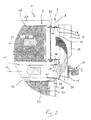
- an exhaust gas treatment device 1 comprises a housing 2 and at least one tube arrangement 3.
- the housing 2 has at least one inlet 4 and at least one outlet 5.
- the housing 2 has in the embodiment shown here two end floors 6 and 7 and an intermediate bottom 8.
- the first end floor 6 bounded with the intermediate bottom 8 in the housing 2 an inlet chamber 9.
- At the first end floor 6 of the inlet 4 is connected in the form of an inlet nozzle.
- the tube assembly 3 comprises at least two tubes communicating with each other, namely a first tube 10 and a second tube 11.
- the first tube 10 communicates on the input side with the inlet chamber 9 and on the output side with a deflection chamber 12.
- the first tube 10 is in an input section 13 on a support member attached, which is formed here by the housing 2 or by a part of the housing 2, namely here by the intermediate bottom 8.
- the first tube 10 with a sliding seat 15 also on the support member, that is supported on the housing 2, namely on the second end floor 7.
- the second tube 11 communicates on the input side with the deflection chamber 12 and the output side with a chamber 16, as a further Deflection chamber or can serve as a distribution chamber.
- an inlet 17 of the second tube 11 communicates with an outlet 18 of the first tube 10. Since the deflection chamber 12 connects the two tubes 10, 11 communicating with each other, it can also be referred to below as a connecting chamber 12.
- the second tube 11 is now supported in an input portion 19 with a sliding seat 20 on the support member, ie on the housing 2, especially on the second end floor 7.
- the second tube 11 in an output section 21 is likewise fastened to the carrier component, that is to say to the housing 2.
- the housing 2 for forming the chamber 16 includes a shell body 22 to which the second tube 11 is fixed in its output section 21.
- the first tube 10 has a first longitudinal central axis 23.
- the second tube 11 accordingly has a second longitudinal central axis 24.
- the two longitudinal central axes 23, 24 extend parallel to one another. Both tubes 10, 11 pass through the respective bottom 7 in separate openings.
- the outlet 18 of the first tube 10 and the inlet 17 of the second tube 11 respectively open in the connecting chamber 12.
- the connecting chamber 12 is here formed by one or more shell body 25, which is connected to the outlet portion 14 of the first tube 10th and are attached to the input portion 19 of the second tube 11.
- said shell body 25 are grown on the second end floor 7.
- a connecting chamber 12 instead of a connecting chamber 12, a correspondingly curved connecting pipe is used to connect the two tubes 10, 11 together. Said connecting tube then connects the outlet 18 of the first tube 10 with the inlet 17 of the second tube 11.
- an exhaust gas treatment device 1 which can be used in an exhaust system of an internal combustion engine, this internal combustion engine can be located in particular in a motor vehicle, preferably in a commercial vehicle.
- the exhaust gas treatment device 1 is designed multifunctional here and contains at least one particle filter element 26, which is arranged in the first tube 10.
- the exhaust gas treatment device 1 here has at least one oxidation catalytic converter element 27, which is likewise arranged here in the first tube 10, namely expediently upstream of the particle filter element 26.
- the exhaust gas treatment device 1 can fulfill a silencer function.
- the first tube 10 here has a radially removable axial section 28, which is characterized here by a curly bracket.
- Said axial section 28 is fastened by means of quick-fastening elements 41, for example in the form of clamps or the like, to the other sections of the first tube 10.
- quick-fastening elements 41 for example in the form of clamps or the like
- corresponding flanges may be formed, with which the fastening elements 41 cooperate.
- the particle filter element 26 is expediently arranged within the radially removable axial section 28. In this way, the respective particulate filter element 26 can be easily renewed or replaced, for example. Appropriately, the entire unit is exchanged from axial section 28 and particulate filter element 26 introduced therein.
- a third tube 29 is also provided, whose longitudinal center axis 30 can also be aligned parallel to the longitudinal central axes 23, 24 of the two other tubes 10, 11.
- An inlet 31 of the third tube 29 communicates with an outlet 32 of the second tube 11.
- the second tube 11 and the third tube 29 open into the chamber 16 so as to communicate with each other the two tubes 11, 29 manufactures.
- the third pipe 29 may include at least one SCR catalyst 33.
- three such catalyst elements 33 in the third tube 29 are arranged one behind the other. With the help of such an SCR catalyst 33, a selective catalytic reduction of certain pollutants can be realized.
- the exhaust gas treatment device 1 also has a metering device 34, with the aid of which a liquid educt can be introduced into the exhaust gas stream.
- a liquid educt can be introduced into the exhaust gas stream.
- ammonia or urea or preferably an aqueous urea solution can be introduced into the exhaust gas flow with the aid of the metering device.
- Urea can be treated by a hydrolysis reaction to ammonia. With the help of ammonia, nitrogen oxides can be converted into nitrogen.
- the corresponding reactions take place in the SCR catalytic converter 33; for example, the first catalyst element 33 through which it flows can facilitate the hydrolysis, while ammonia is reacted in the following elements 33.
- the metering device 34 can be arranged or configured such that it introduces the respective educt in any case upstream of the SCR catalyst 33 in the exhaust gas stream. Expediently, the injection takes place downstream of the particle filter 26. In principle, the injection into the deflection chamber 12 can take place.
- the metering device 34 preferably introduces the educt into the inlet section 19 of the second tube 11. However, the injection of the reactant can also take place upstream of the second tube 11.
- the second tube 11 can serve as a mixing section for exhaust gas and introduced educt to realize an intensive mixing of exhaust gas and educt.
- the exhaust gas treatment device also has a fourth tube 35 which leads to the outlet 5 or which is connected to the exit 5 designed as outlet nozzle.
- An inlet 36 of the fourth tube 35 communicates with an outlet 37 of the third tube 29.
- a longitudinal central axis 40 of the fourth tube 35 extends in the present case again parallel to the longitudinal center axes 23, 24 of the first tube 10 and the second tube 11th
- a single first tube 10, a single second tube 11, a single third tube 29 and a single fourth tube 35 can be seen in each case. It is clear that in particular embodiments at least one of said tubes 10, 11, 29, 35 can also be present multiple times.
- a plurality of second tubes 11 and / or a plurality of third tubes 29 may be provided with SCR catalysts 33.
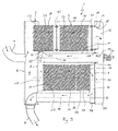
- Corresponding Fig. 2 has the sliding seat 15, with which the first tube 10 on the support member 2 and housing 2 is stored, a bearing material 42.
- This bearing material 42 is arranged stationary with respect to the component 2, that is to say with respect to the housing 2, and is supported radially on the outside of the first tube 10.
- the tube 10 can thus move in its axial direction along the bearing material 42.
- the bearing material 42 itself is indirectly fixed to the housing 2.
- a bearing material 42 which radially on the one hand radially on the second tube 11 is supported radially and indirectly on the component 2 and am Housing 2 is fixed.
- the respective sliding seat 15 or 20 corresponding to the Fig. 3 to 6 a holding tube 43, which is fixedly arranged or formed on the component 2 or on the housing 2, here on the end base 7 thereof.
- the holding tube 43 encloses the respective tube 10 or 11 coaxially.
- the holding tube 43 serves for the radial and axial support of the bearing material 42.
- the bearing material 42 is arranged radially between the holding tube 43 and the respective tube 10, 11.
- the bearing material 42 encloses the respective tube 10, 11 completely in the circumferential direction.
- the bearing material 42 allows low-wear relative movements of the respective tube 10, 11 in the sliding seat 15, 20 and can additionally realize a sufficient gas tightness. Furthermore, it is possible, for example, to make better use of existing spaces in a silencer.
- the bearing material 42 may be, for example, a fiber mat or a wire mesh or another elastic, temperature-resistant material.
- a fiber mat for example, bearing mats or insulating mats of alumina fibers, mullite fibers, glass fibers or similar, temperature-resistant fibers come into question, which are characterized by sufficient elasticity and tightness and by a comparatively low coefficient of friction.
- Such fiber mats are used, for example, for the storage of monoliths in catalysts or particulate filters.
- the fiber mat has a fabric with an oriented fiber direction, it may be expedient to attach the fiber mat in the holding tube 43 such that it has inclined fiber directions at least in a sliding region supported on the tube 10, 11 with respect to the longitudinal central axis 23, 24 of the respective tube 10, 11 having.
- a section of the sliding region designated by 44 of the bearing mat designated 45 is indicated.
- the fibers of the fiber mat 45 extend in the sliding region 44 at approximately 45 ° with respect to the longitudinal central axis 23 or 24 of the tube 10, 11.
- Such knitted fabrics are characterized by a relatively high temperature resistance and by a certain spring elasticity.
- the respective seat 15 or 20 can radially fix the respective tube 10, 11 and nevertheless allow axial relative movements between tube 10, 11 and housing 2 or second end base 7.
- the knitted wire mesh can consist of a plurality of knitted cushions which are distributed in the circumferential direction and spaced apart from one another.
- the wire mesh is in several parts, that is formed from several separate knitted cushions.
- the respective wire mesh is preferably designed so that it consists of at least one knitted ring which includes the respective tube 10, 11 in the circumferential direction closed annular. If several knitted rings are present, these are expediently arranged axially next to one another.
- the holding tube 43 is preferably a body produced separately from the component 2 or housing 2. Accordingly, the holding tube 43 is attached to the housing 2 or component 2. According to Fig. 4 Alternatively, the holding tube 43 can also be an integral component of the respective component 2, that is, the housing 2 here. The holding tube 43 is here formed integrally on the respective component 2.
- the holding tube 43 may have a radial at least one of its axial ends inwardly projecting collar 46 integrally formed on the holding tube 43.
- the collar 46 may be closed in the circumferential direction or looped in segments. It serves for the axial support of the bearing material 42.
- a collar 46 is formed at each axial end of the holding tube 43.
- a radially inwardly projecting bead 47 is formed integrally on the holding tube 43 between its axial ends. This bead 47 may also be closed or segmented in the circumferential direction. Also, the bead 47 serves for the axial support of the bearing mat 42nd
- a cover 48 is formed, which serves for the axial support of the bearing material 42.
- the respective cover 48 protrudes radially inwardly relative to the holding tube 43.
- the cover 48 may be closed in the circumferential direction or extend in segments.
- the cover 48 is a separate component that is attached to the housing 2.
- the cover 48 is integrally formed on the housing 2. In the example, for this purpose, the housing 2 is extended in the region of its inner bottom 7 via the holding tube 43 projecting radially inwardly.
- FIGS. 7 and 8 is the on the pipe 10, 11 supporting sliding portion 44 of the bearing material 42 clearly visible.
- at least this sliding region 44 is formed by a sliding fabric 49, which is arranged in a suitable manner on the fiber mat 45 or on the bearing material 42.
- the sliding fabric 49 encloses the fiber mat 45 like a tube.
- Fig. 8 a layer structure in which the fiber mat 45 via the sliding fabric 49 on the pipe 10, 11 is supported.
- the sliding fabric 49 forms only the radially inner sliding region 44 of the bearing material 42.
- the sliding fabric 49 may be formed of a glass fiber fabric and / or a ceramic fiber fabric.
- the sliding fabric is characterized by a reduced frictional resistance, whereby the wear in the sliding seat 15, 20, can be reduced.
- the referring to Fig. 3 Fiber orientation of the fiber mat 45 described applies analogously to the sliding fabric 49, if this is provided to form the sliding portion 44.
- the bearing material 42 may be pre-pressed or biased in the installed state at least in the radial direction, so that in the sliding seat 15, 20 a radially biased contact between bearing material 42 and tube 10, 11 can be realized.
- To install the respective tube 10, 11 may have a cone, not shown here end.
- the tube 10, 11 may have a friction-reducing or wear-reducing outer side, at least in the area of the sliding seat 15, 20.
- the tube 10, 11 made of a correspondingly smooth material, e.g. cold-rolled sheet.
- the surface can be polished.
- a wear-reducing surface coating can be provided.
- the surface may be hardened and / or nitrided.
- the respective sliding seat 15, 20, a heat-resistant lubricant are added, which is introduced, for example, in the bearing material 42.
- the bearing material 42 it is expedient to match the material selection and / or the dimensioning to the expected during operation of the respective application thermal expansion on the pipe 10, 11 on the one hand and the housing 2 on the other hand, so that always a sufficient elasticity is ensured, for example, always to be able to achieve a sufficient radial pressure on the tube 10, 11 and thus a sufficient sealing effect.
- the embodiment according to Fig. 9 differs from the according to Fig. 1 only in that the deflection chamber 12 now extends over the entire height or side of the second end floor 7 or the exhaust gas treatment device 1. As a result, a reduction in the backpressure can be achieved.
- a cup-shaped lid body 50 is attached to the second end floor 7, so that the deflection chamber 12 is enclosed or bounded by the second end floor 7 and the lid body 50.
- forms in the embodiment according to Fig. 1 forms in the embodiment according to Fig. 1 the shell body 25 with thereof enclosed or limited deflection chamber 12 with respect to the second end plate 7 separate component.
- both the shell body 25, which is separate relative to the second end floor 7, for forming the deflection chamber 12 and the cover body 50 extending over the entire second end floor 7 and fastened thereto are provided.
- the deflection chamber 12 is chambered twice within the exhaust gas treatment device 1, namely within the shell body 25 and within the cover body 50.
- the interior of the shell body 25 is gas-tight from the interior of the cover body 50 separated.
- the cover body 50 together with the second end floor 7 form the space or the chamber 38, which deflects the exhaust gas from the third pipe 29 into the fourth pipe 35.
- the other shell body 39 which in the embodiments of Fig. 1 and 9 forms said deflection space 38 and encloses.
Landscapes
- Engineering & Computer Science (AREA)
- Chemical & Material Sciences (AREA)
- Combustion & Propulsion (AREA)
- Mechanical Engineering (AREA)
- General Engineering & Computer Science (AREA)
- Chemical Kinetics & Catalysis (AREA)
- Health & Medical Sciences (AREA)
- Toxicology (AREA)
- Exhaust Gas After Treatment (AREA)
- Exhaust Silencers (AREA)
- Processes For Solid Components From Exhaust (AREA)
- Accommodation For Nursing Or Treatment Tables (AREA)
Applications Claiming Priority (1)
| Application Number | Priority Date | Filing Date | Title |
|---|---|---|---|
| DE102007062662A DE102007062662A1 (de) | 2007-12-24 | 2007-12-24 | Schiebesitz und Abgasbehandlungseinrichtung |
Publications (2)
| Publication Number | Publication Date |
|---|---|
| EP2075426A1 true EP2075426A1 (fr) | 2009-07-01 |
| EP2075426B1 EP2075426B1 (fr) | 2010-11-10 |
Family
ID=40474828
Family Applications (1)
| Application Number | Title | Priority Date | Filing Date |
|---|---|---|---|
| EP08171414A Active EP2075426B1 (fr) | 2007-12-24 | 2008-12-12 | Ajustement glissant et dispositif de traitement des gaz d'échappement |
Country Status (6)
| Country | Link |
|---|---|
| US (1) | US8713925B2 (fr) |
| EP (1) | EP2075426B1 (fr) |
| JP (1) | JP5271690B2 (fr) |
| CN (1) | CN101504098B (fr) |
| AT (1) | ATE487860T1 (fr) |
| DE (2) | DE102007062662A1 (fr) |
Cited By (11)
| Publication number | Priority date | Publication date | Assignee | Title |
|---|---|---|---|---|
| EP2233708A1 (fr) * | 2009-03-26 | 2010-09-29 | J. Eberspächer GmbH & Co. KG | Dispositif de traitement des gaz d'échappement |
| US20100269495A1 (en) * | 2009-04-24 | 2010-10-28 | Mueller Bernd | Housing for an exhaust gas-treating device and process for manufacturing same |
| EP2261475A1 (fr) * | 2009-06-10 | 2010-12-15 | J. Eberspächer GmbH & Co. KG | Dispositif de purification de gaz d'échappement |
| WO2014107129A1 (fr) * | 2013-01-04 | 2014-07-10 | Scania Cv Ab | Silencieux comprenant un filtre à particules, un tube de vaporisation et un catalyseur de réduction catalytique sélective (scr) |
| CN104066948A (zh) * | 2012-08-10 | 2014-09-24 | 波森公司 | 用于引导气流的设备 |
| EP2420656A3 (fr) * | 2010-08-19 | 2015-03-25 | Eberspächer Exhaust Technology GmbH & Co. KG | Dispositif de nettoyage des gaz d'échappement, installation de gaz d'échappement, procédé de démontage |
| EP2843305A4 (fr) * | 2012-08-07 | 2015-12-02 | Hino Motors Ltd | Brûleur destiné à des dispositifs de purification de gaz d'échappement |
| US9243531B2 (en) | 2012-08-07 | 2016-01-26 | Hino Motors, Ltd. | Burner for exhaust gas purification devices |
| US9746175B2 (en) | 2012-08-07 | 2017-08-29 | Hino Motors, Ltd. | Burner |
| US9765662B2 (en) | 2012-08-13 | 2017-09-19 | Hine Motors, Ltd. | Burner |
| WO2020049084A1 (fr) * | 2018-09-06 | 2020-03-12 | Cnh Industrial Italia S.P.A. | Système de post-traitement amélioré pour un véhicule |
Families Citing this family (19)
| Publication number | Priority date | Publication date | Assignee | Title |
|---|---|---|---|---|
| US20100186394A1 (en) * | 2009-01-26 | 2010-07-29 | Caterpillar Inc. | Exhaust gas after treatment assembly |
| DE102009059684A1 (de) * | 2009-12-19 | 2011-06-22 | J. Eberspächer GmbH & Co. KG, 73730 | Abgasbehandlungseinrichtung |
| US8596049B2 (en) * | 2009-12-22 | 2013-12-03 | Caterpillar Inc. | Exhaust system having an aftertreatment module |
| US8460610B2 (en) * | 2009-12-22 | 2013-06-11 | Caterpillar Inc. | Canister aftertreatment module |
| JP5555023B2 (ja) * | 2010-03-19 | 2014-07-23 | 日野自動車株式会社 | 排気浄化装置 |
| US20130171035A1 (en) * | 2012-01-04 | 2013-07-04 | Tenneco Automotive Operating Company Inc. | Fully insulated exhaust treatment device |
| JP5295403B2 (ja) * | 2012-03-02 | 2013-09-18 | 日立造船株式会社 | 船舶用排ガス脱硝反応容器および排ガス脱硝設備 |
| GB201207201D0 (en) * | 2012-04-24 | 2012-06-06 | Perkins Engines Co Ltd | Emissions cleaning module for a diesel engine |
| CN105247187B (zh) * | 2013-04-11 | 2018-06-29 | 珀金斯发动机有限公司 | 排放物清洁模块及安装机构 |
| DE102013210799C5 (de) * | 2013-06-10 | 2020-07-09 | Eberspächer Exhaust Technology GmbH & Co. KG | Abgasanlage einer Brennkraftmaschine |
| EP2853704B1 (fr) | 2013-09-30 | 2017-04-26 | Kubota Corporation | Moteur diesel |
| JP6087778B2 (ja) * | 2013-09-30 | 2017-03-01 | 株式会社クボタ | ディーゼルエンジン |
| JP6087777B2 (ja) * | 2013-09-30 | 2017-03-01 | 株式会社クボタ | ディーゼルエンジン |
| JP6051154B2 (ja) * | 2013-12-26 | 2016-12-27 | 株式会社クボタ | ディーゼルエンジン |
| DE102015100994A1 (de) * | 2015-01-23 | 2016-07-28 | Faurecia Emissions Control Technologies, Germany Gmbh | Hitzeschildbaugruppe für eine Fahrzeugabgasanlage sowie Abgasanlagenbauteil eines Kraftfahrzeugs |
| CN105649723A (zh) * | 2015-09-18 | 2016-06-08 | 湖北农谷环保科技有限公司 | 一种双筒汽车消音催化器 |
| WO2019055922A1 (fr) | 2017-09-15 | 2019-03-21 | Eberspaecher North America, Inc. | Appareil de post-traitement des gaz d'échappement |
| DE102021111759A1 (de) * | 2021-05-06 | 2022-11-10 | Purem GmbH | Abgasbehandlungsmodul |
| CN116752701B (zh) * | 2023-07-05 | 2023-11-28 | 中国建筑第五工程局有限公司 | 基于bim的装配式建筑构件 |
Citations (6)
| Publication number | Priority date | Publication date | Assignee | Title |
|---|---|---|---|---|
| DE3922667A1 (de) * | 1989-03-17 | 1990-09-27 | Eberspaecher J | Vorrichtung zur katalytischen entgiftung oder dgl. von verbrennungsmotor-abgasen mit doppelwandigem gehaeuse |
| EP0537603A1 (fr) * | 1991-10-18 | 1993-04-21 | Firma J. Eberspächer | Tuyau à paroi double, isolé par de l'air, pour des installations d'échappement de véhicules |
| EP0580963A1 (fr) * | 1992-07-27 | 1994-02-02 | Witzenmann GmbH Metallschlauch-Fabrik Pforzheim | Conduite articulée |
| DE4318343A1 (de) * | 1993-06-02 | 1994-12-08 | Iwk Regler Kompensatoren | Vorrichtung zum Dämpfen von Schwingungen in einer Abgasanlage eines Fahrzeugs |
| DE19918301C1 (de) * | 1999-04-22 | 2000-10-26 | Zeuna Staerker Kg | Teilsystem einer Abgasanlage für ein Kraftfahrzeug |
| EP1329608A2 (fr) * | 2002-01-22 | 2003-07-23 | Faurecia Abgastechnik GmbH | Système d'échappement pour véhicule automobile |
Family Cites Families (33)
| Publication number | Priority date | Publication date | Assignee | Title |
|---|---|---|---|---|
| US2217664A (en) * | 1937-12-18 | 1940-10-15 | Adolph L Berger | Exhaust manifold |
| JPS6159824U (fr) * | 1984-09-25 | 1986-04-22 | ||
| JPH0241293Y2 (fr) * | 1984-09-26 | 1990-11-02 | ||
| US4565380A (en) * | 1984-11-21 | 1986-01-21 | Precision Tube Bending | Seal with two sealing portions having flange receiving opening therebetween |
| DE8812762U1 (fr) * | 1988-10-11 | 1989-06-29 | Emitec Emissionstechnologie | |
| US5190732A (en) * | 1988-10-11 | 1993-03-02 | Emitec Gesellschaft Fur Emissionstechnologie Mbh | Catalyst with a double casing system |
| JPH0442489Y2 (fr) * | 1988-12-02 | 1992-10-07 | ||
| DE3908887A1 (de) * | 1989-03-17 | 1990-09-20 | Eberspaecher J | Vorrichtung zur katalytischen entgiftung oder dgl. von verbrennungsmotor-abgasen mit zwei abgas-behandlungskoerpern und einem schutzring dazwischen |
| US5145215A (en) * | 1991-04-26 | 1992-09-08 | Senior Engineering Investments, B.V. | Flexible coupler apparatus |
| DE9205294U1 (fr) * | 1992-04-16 | 1992-06-17 | Heinrich Gillet Gmbh & Co Kg, 6732 Edenkoben, De | |
| JPH06159824A (ja) | 1992-11-18 | 1994-06-07 | Fujitsu General Ltd | 空気調和機の制御方法 |
| JPH06159823A (ja) | 1992-11-25 | 1994-06-07 | Toshiba Corp | 空気調和機 |
| EP0662564B2 (fr) * | 1994-01-07 | 2001-09-26 | J. Eberspächer GmbH & Co. | Conduit de gaz d'échappement isolé par une couche d'air et méthode de construction |
| DE19829110A1 (de) * | 1998-06-30 | 2000-01-05 | Eberspaecher J Gmbh & Co | Fasermatte |
| US6131960A (en) * | 1998-10-16 | 2000-10-17 | Mchughs; Larry | Packing sealed expansion joint |
| US6265078B1 (en) * | 1999-09-09 | 2001-07-24 | Northrop Grumman Corporation | Reducing wear between structural fiber reinforced ceramic matrix composite automotive engine parts in sliding contacting relationship |
| DE10105841C2 (de) * | 2001-02-07 | 2002-12-12 | Benteler Automobiltechnik Gmbh | Abgasleitung mit Luftspaltisolierung für eine Brennkraftmaschine |
| DE10250050A1 (de) * | 2002-10-25 | 2004-05-06 | Purem Abgassysteme Gmbh & Co. Kg | Abgasnachbehandlungssystem, insbesondere für einen Dieselmotor |
| DE10300780A1 (de) * | 2003-01-11 | 2004-07-22 | J. Eberspächer GmbH & Co. KG | Abgasbehandlungseinrichtung |
| WO2004071646A2 (fr) * | 2003-02-12 | 2004-08-26 | Delphi Technologies, Inc. | Systeme et procede de reduction des oxydes d'azote |
| DE10334307B4 (de) * | 2003-07-28 | 2008-06-26 | Benteler Automobiltechnik Gmbh | Isolierte Abgasleitung |
| JP2005155404A (ja) * | 2003-11-25 | 2005-06-16 | Komatsu Ltd | 内燃機関の排気ガス浄化装置 |
| US7051523B2 (en) * | 2004-03-10 | 2006-05-30 | General Motors Corporation | Exhaust system assemblies employing wire bushings for thermal compensation |
| JP3715981B2 (ja) * | 2004-03-25 | 2005-11-16 | 日産ディーゼル工業株式会社 | 排気浄化機能付き消音装置 |
| DE102004021196B4 (de) * | 2004-04-29 | 2006-10-05 | J. Eberspächer GmbH & Co. KG | Luftspaltisolierter Abgaskrümmer |
| DE102004021474B3 (de) * | 2004-04-30 | 2005-03-10 | Audi Ag | Vorrichtung zur Aufhängung eines dyanmisch beanspruchten Funktionsteiles |
| US7323030B2 (en) * | 2004-10-28 | 2008-01-29 | Delphi Technologies, Inc. | Apparatus and method for an exhaust aftertreatment device |
| DE102005002289B4 (de) * | 2005-01-17 | 2007-04-19 | J. Eberspächer GmbH & Co. KG | Abgasbehandlungssystem |
| DE102005031677B4 (de) * | 2005-07-05 | 2007-11-29 | J. Eberspächer GmbH & Co. KG | Abgasbehandlungseinrichtung und zugehöriges Herstellungsverfahren |
| DE102005046317A1 (de) * | 2005-09-27 | 2007-04-05 | J. Eberspächer GmbH & Co. KG | Abgasbehandlungseinrichtung |
| JP4538397B2 (ja) * | 2005-09-29 | 2010-09-08 | 株式会社クボタ | エンジン |
| JP4687496B2 (ja) | 2006-02-20 | 2011-05-25 | 三菱樹脂株式会社 | モノリス保持材 |
| US8230678B2 (en) * | 2007-06-21 | 2012-07-31 | Daimler Trucks North America Llc | Treatment of diesel engine exhaust |
-
2007
- 2007-12-24 DE DE102007062662A patent/DE102007062662A1/de not_active Withdrawn
-
2008
- 2008-12-12 EP EP08171414A patent/EP2075426B1/fr active Active
- 2008-12-12 AT AT08171414T patent/ATE487860T1/de active
- 2008-12-12 DE DE502008001757T patent/DE502008001757D1/de active Active
- 2008-12-17 CN CN2008101872331A patent/CN101504098B/zh active Active
- 2008-12-17 US US12/337,035 patent/US8713925B2/en active Active
- 2008-12-22 JP JP2008324858A patent/JP5271690B2/ja active Active
Patent Citations (6)
| Publication number | Priority date | Publication date | Assignee | Title |
|---|---|---|---|---|
| DE3922667A1 (de) * | 1989-03-17 | 1990-09-27 | Eberspaecher J | Vorrichtung zur katalytischen entgiftung oder dgl. von verbrennungsmotor-abgasen mit doppelwandigem gehaeuse |
| EP0537603A1 (fr) * | 1991-10-18 | 1993-04-21 | Firma J. Eberspächer | Tuyau à paroi double, isolé par de l'air, pour des installations d'échappement de véhicules |
| EP0580963A1 (fr) * | 1992-07-27 | 1994-02-02 | Witzenmann GmbH Metallschlauch-Fabrik Pforzheim | Conduite articulée |
| DE4318343A1 (de) * | 1993-06-02 | 1994-12-08 | Iwk Regler Kompensatoren | Vorrichtung zum Dämpfen von Schwingungen in einer Abgasanlage eines Fahrzeugs |
| DE19918301C1 (de) * | 1999-04-22 | 2000-10-26 | Zeuna Staerker Kg | Teilsystem einer Abgasanlage für ein Kraftfahrzeug |
| EP1329608A2 (fr) * | 2002-01-22 | 2003-07-23 | Faurecia Abgastechnik GmbH | Système d'échappement pour véhicule automobile |
Cited By (17)
| Publication number | Priority date | Publication date | Assignee | Title |
|---|---|---|---|---|
| EP2233708B1 (fr) | 2009-03-26 | 2016-07-27 | Eberspächer Exhaust Technology GmbH & Co. KG | Dispositif de traitement des gaz d'échappement |
| EP2233708A1 (fr) * | 2009-03-26 | 2010-09-29 | J. Eberspächer GmbH & Co. KG | Dispositif de traitement des gaz d'échappement |
| US8621853B2 (en) | 2009-03-26 | 2014-01-07 | Eberspächer Exhaust Technology GmbH & Co. KG | Exhaust gas-treating device |
| US20100269495A1 (en) * | 2009-04-24 | 2010-10-28 | Mueller Bernd | Housing for an exhaust gas-treating device and process for manufacturing same |
| US8790582B2 (en) * | 2009-04-24 | 2014-07-29 | Eberspächer Exhaust Technology GmbH & Co. KG | Housing for an exhaust gas-treating device and process for manufacturing same |
| EP2261475A1 (fr) * | 2009-06-10 | 2010-12-15 | J. Eberspächer GmbH & Co. KG | Dispositif de purification de gaz d'échappement |
| US8568661B2 (en) | 2009-06-10 | 2013-10-29 | Eberspächer Exhaust Technology GmbH & Co. KG | Exhaust gas treatment device |
| EP2420656A3 (fr) * | 2010-08-19 | 2015-03-25 | Eberspächer Exhaust Technology GmbH & Co. KG | Dispositif de nettoyage des gaz d'échappement, installation de gaz d'échappement, procédé de démontage |
| US9746175B2 (en) | 2012-08-07 | 2017-08-29 | Hino Motors, Ltd. | Burner |
| US9243531B2 (en) | 2012-08-07 | 2016-01-26 | Hino Motors, Ltd. | Burner for exhaust gas purification devices |
| US9249704B2 (en) | 2012-08-07 | 2016-02-02 | Hino Motors, Ltd. | Burner for exhaust gas purification devices |
| EP2843305A4 (fr) * | 2012-08-07 | 2015-12-02 | Hino Motors Ltd | Brûleur destiné à des dispositifs de purification de gaz d'échappement |
| CN104066948A (zh) * | 2012-08-10 | 2014-09-24 | 波森公司 | 用于引导气流的设备 |
| US9765662B2 (en) | 2012-08-13 | 2017-09-19 | Hine Motors, Ltd. | Burner |
| WO2014107129A1 (fr) * | 2013-01-04 | 2014-07-10 | Scania Cv Ab | Silencieux comprenant un filtre à particules, un tube de vaporisation et un catalyseur de réduction catalytique sélective (scr) |
| WO2020049084A1 (fr) * | 2018-09-06 | 2020-03-12 | Cnh Industrial Italia S.P.A. | Système de post-traitement amélioré pour un véhicule |
| US11519314B2 (en) | 2018-09-06 | 2022-12-06 | Cnh Industrial America Llc | After treatment system for a vehicle |
Also Published As
| Publication number | Publication date |
|---|---|
| US8713925B2 (en) | 2014-05-06 |
| ATE487860T1 (de) | 2010-11-15 |
| CN101504098A (zh) | 2009-08-12 |
| DE502008001757D1 (de) | 2010-12-23 |
| US20090158720A1 (en) | 2009-06-25 |
| CN101504098B (zh) | 2012-09-26 |
| JP2009150394A (ja) | 2009-07-09 |
| DE102007062662A1 (de) | 2009-06-25 |
| JP5271690B2 (ja) | 2013-08-21 |
| EP2075426B1 (fr) | 2010-11-10 |
Similar Documents
| Publication | Publication Date | Title |
|---|---|---|
| EP2075426B1 (fr) | Ajustement glissant et dispositif de traitement des gaz d'échappement | |
| EP2075425B1 (fr) | Dispositif de traitement des gaz d'échappement avec agencement de tuyau et siège coulissant | |
| EP2233708B2 (fr) | Dispositif de traitement des gaz d'échappement | |
| EP1728984B1 (fr) | Dispositif d'échappement | |
| EP2233709B1 (fr) | Dispositif de traitement de gaz d'échappement | |
| EP2691618B1 (fr) | Unité de traitement de gaz d'échappement compacte comprenant une zone de mélange et procédé pour mélanger des gaz d'échappement | |
| DE102009030963B4 (de) | Einrichtung und Verfahren zum Kühlen eines Abgases | |
| EP2606208B1 (fr) | Unité de traitement des gaz d'échappement compacte avec ajout de réactif | |
| DE10329000A1 (de) | Abgasnachbehandlungsanlage mit einem Gegenstromgehäuse, sowie entsprechendes Verfahren zur Abgasnachbehandlung | |
| DE102006011091A1 (de) | Komponente einer Abgasanlage | |
| DE202021103400U1 (de) | Fahrzeugabgasanlage mit Endkappenmischer | |
| DE102012017178A1 (de) | Abgasreinigungsvorrichtung | |
| DE102011112988A1 (de) | Abgasanlage für ein Fahrzeug | |
| EP0556846A1 (fr) | Silencieux d'échappement pour moteur diesel et en particulier pour véhicules utilitaires | |
| DE10296178B4 (de) | Flexibles Leitungselement | |
| DE3437641A1 (de) | Abgas-katalysator | |
| DE102018133634A1 (de) | Abgasnachbehandlungssystem für einen Verbrennungsmotor | |
| DE10254036B4 (de) | Mehrbettkatalysator | |
| DE2746475A1 (de) | Vorrichtung zur halterung eines monolithischen traegerkoerpers einer katalytischen abgasreinigungsvorrichtung | |
| EP2194251A1 (fr) | Fixation autoporteuse pour corps de support de catalyseur | |
| DE19755703A1 (de) | Katalysatorträgeranordnung für einen motornahen Einbau | |
| DE10155086A1 (de) | Katalysator-Filter-Anordnung und Verfahren zu ihrer Herstellung | |
| DE102004011844B4 (de) | Abgasreinigungseinrichtung | |
| DE102006059277A1 (de) | Strömungsverteiler für ein Abgassystem | |
| DE102019207603A1 (de) | Abgaskatalyseeinrichtung und Brennkraftmaschine mit einer solchen Abgaskatalyseeinrichtung |
Legal Events
| Date | Code | Title | Description |
|---|---|---|---|
| PUAI | Public reference made under article 153(3) epc to a published international application that has entered the european phase |
Free format text: ORIGINAL CODE: 0009012 |
|
| AK | Designated contracting states |
Kind code of ref document: A1 Designated state(s): AT BE BG CH CY CZ DE DK EE ES FI FR GB GR HR HU IE IS IT LI LT LU LV MC MT NL NO PL PT RO SE SI SK TR |
|
| AX | Request for extension of the european patent |
Extension state: AL BA MK RS |
|
| 17P | Request for examination filed |
Effective date: 20100104 |
|
| AKX | Designation fees paid |
Designated state(s): AT BE BG CH CY CZ DE DK EE ES FI FR GB GR HR HU IE IS IT LI LT LU LV MC MT NL NO PL PT RO SE SI SK TR |
|
| GRAP | Despatch of communication of intention to grant a patent |
Free format text: ORIGINAL CODE: EPIDOSNIGR1 |
|
| RIC1 | Information provided on ipc code assigned before grant |
Ipc: F01N 3/20 20060101ALI20100617BHEP Ipc: F01N 13/16 20100101ALI20100617BHEP Ipc: F01N 1/08 20060101ALI20100617BHEP Ipc: F01N 13/18 20100101ALI20100617BHEP Ipc: F01N 3/022 20060101ALI20100617BHEP Ipc: F01N 3/28 20060101AFI20100617BHEP |
|
| GRAS | Grant fee paid |
Free format text: ORIGINAL CODE: EPIDOSNIGR3 |
|
| GRAA | (expected) grant |
Free format text: ORIGINAL CODE: 0009210 |
|
| AK | Designated contracting states |
Kind code of ref document: B1 Designated state(s): AT BE BG CH CY CZ DE DK EE ES FI FR GB GR HR HU IE IS IT LI LT LU LV MC MT NL NO PL PT RO SE SI SK TR |
|
| REG | Reference to a national code |
Ref country code: GB Ref legal event code: FG4D Free format text: NOT ENGLISH |
|
| REG | Reference to a national code |
Ref country code: CH Ref legal event code: EP |
|
| REG | Reference to a national code |
Ref country code: IE Ref legal event code: FG4D Free format text: LANGUAGE OF EP DOCUMENT: GERMAN |
|
| REF | Corresponds to: |
Ref document number: 502008001757 Country of ref document: DE Date of ref document: 20101223 Kind code of ref document: P |
|
| REG | Reference to a national code |
Ref country code: SE Ref legal event code: TRGR |
|
| REG | Reference to a national code |
Ref country code: NL Ref legal event code: VDEP Effective date: 20101110 |
|
| LTIE | Lt: invalidation of european patent or patent extension |
Effective date: 20101110 |
|
| PG25 | Lapsed in a contracting state [announced via postgrant information from national office to epo] |
Ref country code: LT Free format text: LAPSE BECAUSE OF FAILURE TO SUBMIT A TRANSLATION OF THE DESCRIPTION OR TO PAY THE FEE WITHIN THE PRESCRIBED TIME-LIMIT Effective date: 20101110 Ref country code: NO Free format text: LAPSE BECAUSE OF FAILURE TO SUBMIT A TRANSLATION OF THE DESCRIPTION OR TO PAY THE FEE WITHIN THE PRESCRIBED TIME-LIMIT Effective date: 20110210 |
|
| PG25 | Lapsed in a contracting state [announced via postgrant information from national office to epo] |
Ref country code: IS Free format text: LAPSE BECAUSE OF FAILURE TO SUBMIT A TRANSLATION OF THE DESCRIPTION OR TO PAY THE FEE WITHIN THE PRESCRIBED TIME-LIMIT Effective date: 20110310 Ref country code: CY Free format text: LAPSE BECAUSE OF FAILURE TO SUBMIT A TRANSLATION OF THE DESCRIPTION OR TO PAY THE FEE WITHIN THE PRESCRIBED TIME-LIMIT Effective date: 20101110 Ref country code: LV Free format text: LAPSE BECAUSE OF FAILURE TO SUBMIT A TRANSLATION OF THE DESCRIPTION OR TO PAY THE FEE WITHIN THE PRESCRIBED TIME-LIMIT Effective date: 20101110 Ref country code: BG Free format text: LAPSE BECAUSE OF FAILURE TO SUBMIT A TRANSLATION OF THE DESCRIPTION OR TO PAY THE FEE WITHIN THE PRESCRIBED TIME-LIMIT Effective date: 20110210 Ref country code: NL Free format text: LAPSE BECAUSE OF FAILURE TO SUBMIT A TRANSLATION OF THE DESCRIPTION OR TO PAY THE FEE WITHIN THE PRESCRIBED TIME-LIMIT Effective date: 20101110 Ref country code: PT Free format text: LAPSE BECAUSE OF FAILURE TO SUBMIT A TRANSLATION OF THE DESCRIPTION OR TO PAY THE FEE WITHIN THE PRESCRIBED TIME-LIMIT Effective date: 20110310 Ref country code: FI Free format text: LAPSE BECAUSE OF FAILURE TO SUBMIT A TRANSLATION OF THE DESCRIPTION OR TO PAY THE FEE WITHIN THE PRESCRIBED TIME-LIMIT Effective date: 20101110 Ref country code: SI Free format text: LAPSE BECAUSE OF FAILURE TO SUBMIT A TRANSLATION OF THE DESCRIPTION OR TO PAY THE FEE WITHIN THE PRESCRIBED TIME-LIMIT Effective date: 20101110 Ref country code: HR Free format text: LAPSE BECAUSE OF FAILURE TO SUBMIT A TRANSLATION OF THE DESCRIPTION OR TO PAY THE FEE WITHIN THE PRESCRIBED TIME-LIMIT Effective date: 20101110 |
|
| REG | Reference to a national code |
Ref country code: IE Ref legal event code: FD4D |
|
| BERE | Be: lapsed |
Owner name: J. EBERSPACHER G.M.B.H. & CO. KG Effective date: 20101231 |
|
| PG25 | Lapsed in a contracting state [announced via postgrant information from national office to epo] |
Ref country code: GR Free format text: LAPSE BECAUSE OF FAILURE TO SUBMIT A TRANSLATION OF THE DESCRIPTION OR TO PAY THE FEE WITHIN THE PRESCRIBED TIME-LIMIT Effective date: 20110211 |
|
| PG25 | Lapsed in a contracting state [announced via postgrant information from national office to epo] |
Ref country code: CZ Free format text: LAPSE BECAUSE OF FAILURE TO SUBMIT A TRANSLATION OF THE DESCRIPTION OR TO PAY THE FEE WITHIN THE PRESCRIBED TIME-LIMIT Effective date: 20101110 Ref country code: EE Free format text: LAPSE BECAUSE OF FAILURE TO SUBMIT A TRANSLATION OF THE DESCRIPTION OR TO PAY THE FEE WITHIN THE PRESCRIBED TIME-LIMIT Effective date: 20101110 Ref country code: ES Free format text: LAPSE BECAUSE OF FAILURE TO SUBMIT A TRANSLATION OF THE DESCRIPTION OR TO PAY THE FEE WITHIN THE PRESCRIBED TIME-LIMIT Effective date: 20110221 Ref country code: MC Free format text: LAPSE BECAUSE OF NON-PAYMENT OF DUE FEES Effective date: 20101231 Ref country code: IE Free format text: LAPSE BECAUSE OF FAILURE TO SUBMIT A TRANSLATION OF THE DESCRIPTION OR TO PAY THE FEE WITHIN THE PRESCRIBED TIME-LIMIT Effective date: 20101110 |
|
| PG25 | Lapsed in a contracting state [announced via postgrant information from national office to epo] |
Ref country code: DK Free format text: LAPSE BECAUSE OF FAILURE TO SUBMIT A TRANSLATION OF THE DESCRIPTION OR TO PAY THE FEE WITHIN THE PRESCRIBED TIME-LIMIT Effective date: 20101110 Ref country code: PL Free format text: LAPSE BECAUSE OF FAILURE TO SUBMIT A TRANSLATION OF THE DESCRIPTION OR TO PAY THE FEE WITHIN THE PRESCRIBED TIME-LIMIT Effective date: 20101110 Ref country code: SK Free format text: LAPSE BECAUSE OF FAILURE TO SUBMIT A TRANSLATION OF THE DESCRIPTION OR TO PAY THE FEE WITHIN THE PRESCRIBED TIME-LIMIT Effective date: 20101110 Ref country code: RO Free format text: LAPSE BECAUSE OF FAILURE TO SUBMIT A TRANSLATION OF THE DESCRIPTION OR TO PAY THE FEE WITHIN THE PRESCRIBED TIME-LIMIT Effective date: 20101110 |
|
| PLBE | No opposition filed within time limit |
Free format text: ORIGINAL CODE: 0009261 |
|
| STAA | Information on the status of an ep patent application or granted ep patent |
Free format text: STATUS: NO OPPOSITION FILED WITHIN TIME LIMIT |
|
| PG25 | Lapsed in a contracting state [announced via postgrant information from national office to epo] |
Ref country code: BE Free format text: LAPSE BECAUSE OF NON-PAYMENT OF DUE FEES Effective date: 20101231 |
|
| 26N | No opposition filed |
Effective date: 20110811 |
|
| REG | Reference to a national code |
Ref country code: DE Ref legal event code: R097 Ref document number: 502008001757 Country of ref document: DE Effective date: 20110811 |
|
| PG25 | Lapsed in a contracting state [announced via postgrant information from national office to epo] |
Ref country code: MT Free format text: LAPSE BECAUSE OF FAILURE TO SUBMIT A TRANSLATION OF THE DESCRIPTION OR TO PAY THE FEE WITHIN THE PRESCRIBED TIME-LIMIT Effective date: 20101110 |
|
| PG25 | Lapsed in a contracting state [announced via postgrant information from national office to epo] |
Ref country code: HU Free format text: LAPSE BECAUSE OF FAILURE TO SUBMIT A TRANSLATION OF THE DESCRIPTION OR TO PAY THE FEE WITHIN THE PRESCRIBED TIME-LIMIT Effective date: 20110511 Ref country code: LU Free format text: LAPSE BECAUSE OF NON-PAYMENT OF DUE FEES Effective date: 20101212 |
|
| PG25 | Lapsed in a contracting state [announced via postgrant information from national office to epo] |
Ref country code: TR Free format text: LAPSE BECAUSE OF FAILURE TO SUBMIT A TRANSLATION OF THE DESCRIPTION OR TO PAY THE FEE WITHIN THE PRESCRIBED TIME-LIMIT Effective date: 20101110 |
|
| REG | Reference to a national code |
Ref country code: CH Ref legal event code: PL |
|
| REG | Reference to a national code |
Ref country code: GB Ref legal event code: 732E Free format text: REGISTERED BETWEEN 20130905 AND 20130911 |
|
| REG | Reference to a national code |
Ref country code: DE Ref legal event code: R082 Ref document number: 502008001757 Country of ref document: DE Representative=s name: BRP RENAUD & PARTNER, DE |
|
| PG25 | Lapsed in a contracting state [announced via postgrant information from national office to epo] |
Ref country code: CH Free format text: LAPSE BECAUSE OF NON-PAYMENT OF DUE FEES Effective date: 20121231 Ref country code: LI Free format text: LAPSE BECAUSE OF NON-PAYMENT OF DUE FEES Effective date: 20121231 |
|
| REG | Reference to a national code |
Ref country code: DE Ref legal event code: R082 Ref document number: 502008001757 Country of ref document: DE Representative=s name: BRP RENAUD UND PARTNER MBB RECHTSANWAELTE PATE, DE Effective date: 20131022 Ref country code: DE Ref legal event code: R082 Ref document number: 502008001757 Country of ref document: DE Representative=s name: BRP RENAUD UND PARTNER MBB, DE Effective date: 20131022 Ref country code: DE Ref legal event code: R082 Ref document number: 502008001757 Country of ref document: DE Representative=s name: BRP RENAUD & PARTNER, DE Effective date: 20131022 Ref country code: DE Ref legal event code: R081 Ref document number: 502008001757 Country of ref document: DE Owner name: EBERSPAECHER EXHAUST TECHNOLOGY GMBH & CO. KG, DE Free format text: FORMER OWNER: J. EBERSPAECHER GMBH & CO. KG, 73730 ESSLINGEN, DE Effective date: 20131022 |
|
| REG | Reference to a national code |
Ref country code: FR Ref legal event code: CD Owner name: EBERSPACHER CLIMATE CONTROL SYSTEMS GMBH & CO. KG Effective date: 20131129 |
|
| REG | Reference to a national code |
Ref country code: FR Ref legal event code: TP Owner name: EBERSPACHER EXHAUST TECHNOLOGY GMBH & CO. KG, DE Effective date: 20140204 |
|
| REG | Reference to a national code |
Ref country code: AT Ref legal event code: MM01 Ref document number: 487860 Country of ref document: AT Kind code of ref document: T Effective date: 20131212 |
|
| PG25 | Lapsed in a contracting state [announced via postgrant information from national office to epo] |
Ref country code: AT Free format text: LAPSE BECAUSE OF NON-PAYMENT OF DUE FEES Effective date: 20131212 |
|
| REG | Reference to a national code |
Ref country code: FR Ref legal event code: PLFP Year of fee payment: 8 |
|
| REG | Reference to a national code |
Ref country code: FR Ref legal event code: PLFP Year of fee payment: 9 |
|
| REG | Reference to a national code |
Ref country code: FR Ref legal event code: PLFP Year of fee payment: 10 |
|
| PGFP | Annual fee paid to national office [announced via postgrant information from national office to epo] |
Ref country code: IT Payment date: 20171218 Year of fee payment: 10 |
|
| PG25 | Lapsed in a contracting state [announced via postgrant information from national office to epo] |
Ref country code: IT Free format text: LAPSE BECAUSE OF NON-PAYMENT OF DUE FEES Effective date: 20181212 |
|
| REG | Reference to a national code |
Ref country code: DE Ref legal event code: R081 Ref document number: 502008001757 Country of ref document: DE Owner name: PUREM GMBH, DE Free format text: FORMER OWNER: EBERSPAECHER EXHAUST TECHNOLOGY GMBH & CO. KG, 66539 NEUNKIRCHEN, DE |
|
| PGFP | Annual fee paid to national office [announced via postgrant information from national office to epo] |
Ref country code: SE Payment date: 20211220 Year of fee payment: 14 |
|
| REG | Reference to a national code |
Ref country code: SE Ref legal event code: EUG |
|
| PG25 | Lapsed in a contracting state [announced via postgrant information from national office to epo] |
Ref country code: SE Free format text: LAPSE BECAUSE OF NON-PAYMENT OF DUE FEES Effective date: 20221213 |
|
| PGFP | Annual fee paid to national office [announced via postgrant information from national office to epo] |
Ref country code: GB Payment date: 20231220 Year of fee payment: 16 |
|
| PGFP | Annual fee paid to national office [announced via postgrant information from national office to epo] |
Ref country code: FR Payment date: 20231220 Year of fee payment: 16 Ref country code: DE Payment date: 20231214 Year of fee payment: 16 |