EP2074902A1 - Electrically driven and heated hair brush - Google Patents
Electrically driven and heated hair brush Download PDFInfo
- Publication number
- EP2074902A1 EP2074902A1 EP09100216A EP09100216A EP2074902A1 EP 2074902 A1 EP2074902 A1 EP 2074902A1 EP 09100216 A EP09100216 A EP 09100216A EP 09100216 A EP09100216 A EP 09100216A EP 2074902 A1 EP2074902 A1 EP 2074902A1
- Authority
- EP
- European Patent Office
- Prior art keywords
- hair
- hairbrush
- styling device
- bristles
- bristle
- Prior art date
- Legal status (The legal status is an assumption and is not a legal conclusion. Google has not performed a legal analysis and makes no representation as to the accuracy of the status listed.)
- Granted
Links
Images
Classifications
-
- A—HUMAN NECESSITIES
- A45—HAND OR TRAVELLING ARTICLES
- A45D—HAIRDRESSING OR SHAVING EQUIPMENT; EQUIPMENT FOR COSMETICS OR COSMETIC TREATMENTS, e.g. FOR MANICURING OR PEDICURING
- A45D20/00—Hair drying devices; Accessories therefor
- A45D20/48—Hair-drying combs or hair-drying brushes, with internal heating means
- A45D20/50—Hair-drying combs or hair-drying brushes, with internal heating means and provision for an air stream
-
- A—HUMAN NECESSITIES
- A46—BRUSHWARE
- A46B—BRUSHES
- A46B15/00—Other brushes; Brushes with additional arrangements
- A46B15/0002—Arrangements for enhancing monitoring or controlling the brushing process
- A46B15/0016—Arrangements for enhancing monitoring or controlling the brushing process with enhancing means
- A46B15/003—Enhancing with heat
-
- A—HUMAN NECESSITIES
- A46—BRUSHWARE
- A46B—BRUSHES
- A46B13/00—Brushes with driven brush bodies or carriers
- A46B13/02—Brushes with driven brush bodies or carriers power-driven carriers
-
- A—HUMAN NECESSITIES
- A46—BRUSHWARE
- A46B—BRUSHES
- A46B15/00—Other brushes; Brushes with additional arrangements
- A46B15/0002—Arrangements for enhancing monitoring or controlling the brushing process
-
- A—HUMAN NECESSITIES
- A46—BRUSHWARE
- A46B—BRUSHES
- A46B2200/00—Brushes characterized by their functions, uses or applications
- A46B2200/10—For human or animal care
- A46B2200/104—Hair brush
-
- A—HUMAN NECESSITIES
- A46—BRUSHWARE
- A46B—BRUSHES
- A46B9/00—Arrangements of the bristles in the brush body
- A46B9/02—Position or arrangement of bristles in relation to surface of the brush body, e.g. inclined, in rows, in groups
- A46B9/023—Position or arrangement of bristles in relation to surface of the brush body, e.g. inclined, in rows, in groups arranged like in hair brushes, e.g. hair treatment, dyeing, streaking
Definitions
- the invention relates to an electric hair styling device for shaping waves with a built-in handle warm air blower and with an electric motor driven by a rotating and powered by the hot air blower air stream hairbrush with a shaft and a protruding from the shaft bristles.
- Such hair styling devices are used to form curls in a person's hair.
- the hair is shaped by the electric motor driven by a rotary hair brush, supported by a stream of hot air, which brings the heat required for forming the hair to be formed.
- the electric motor and the hot air blower with heater are typically housed in a tubular, serving as a handle housing.
- the reshaped hairs are basically taken by the rotating hairbrush over more than one hair brush rotation, resulting in the above-described curling or screwing result.
- the hairbrush is rolled into the hair to be reshaped like a curler.
- Such a hair styling device is for example off DE 35 29 267 A1 known.
- the electric motor driving the hairbrush is switched off in good time before the hairbrush is completely screwed into the hair tuft provided for shaping a curl, so that the pull acting on the tuft by the rotating hairbrush does not increase big and possibly painful.
- the electric power supplied to the electric motor is limited by that Power supply of the hair brush driving electric motor is realized via a voltage tap on the heater.
- Such an electric hair styling device is an alternative to a use of curlers. With this electric hair styling device, however, can not form waves, as this is sometimes desired. So-called hair drier waves can be formed conventionally only with a hand brush and a hair dryer, where it requires a lot of skill to train hair drier.
- US Pat. No. 4,023,578 describes an electric hair styling device with a hair brush rotatably mounted on a handle for shaping hair waves.
- the hairbrush itself is not powered.
- the hair styling device described in this document is provided that the hair to be formed comes into contact with the sleeve of the hairbrush, as this has a certain heat storage capacity and the heat stored therein is to be transferred to the hair to be formed.
- the hair is wrapped around the sleeve.
- the bristles of this known hair styling device protrude only about 4 - 5 mm from the surface of this heat-storing sleeve.
- each comb or bristle row is moved out of the sleeve and pulled into it due to its eccentric rotatable mounting relative to the sleeve, so that each row of combs or bristles has only one certain amount of rotation protrudes beyond the outer surface of the sleeve.
- the invention is therefore the object of developing an aforementioned electric hair styling device such that with this hair waves, especially so-called hair dryer waves can be easily formed.
- the hair brush is designed such that a rotational drive on the hair to be formed only to the extent that basically a complete screwing the hair brush is avoided in the hair to be formed.
- a certain rotational drive is necessary to keep the hair to be formed in a shape simulating the wave to be created for the necessary time for shaping the shaft.
- the heat provided by the warm air flow supports the hair-styling process, wherein the hairbrush is expediently designed in the manner of an airbrush and the hot air stream flowing into the hairbrush enters an inner inflow channel of the hairbrush and is led out of it through the air outlet openings located in the hairbrush in the radial direction.
- conditional rotational drive of the hair to be formed with a rotating hairbrush is achieved in that the radially outwardly facing top of the lateral surface of the shaft of the hairbrush has such a nature that transmitted from this no torque on the hair to be formed or at most only a negligibly small becomes.
- This surface is therefore expediently highly smooth and / or has a coating to which the hair to be formed does not adhere when the hairbrush is rotating, as is the case, for example, with a polytetrafluoroethylene coating (PTFE coating).
- PTFE coating polytetrafluoroethylene coating
- the bristles of such a hairbrush may be considered moderately bristled in terms of the density of their bristles.
- the individual bristle tufts themselves are expediently recessed in relation to the jacket surface of the hair dryer, it being provided that the actual anchoring of the foot of the bristle tufts is spaced from the lateral surface by a spacing opening.
- the inwardly facing side of the spacer opening is spaced from the lateral surface of a bristle tuft so that it can be reciprocated within the spacer opening.
- the distance opening serves the purpose that the bristle tufts already at the top of the lateral surface of the shank of the hairbrush have a certain softness or compliance and in this area are only loosely together. Hair gripped by such a bristle tuft, when attracted to the surface of the hair dryer, may also slide between the individual hairs of a bristle tuft without being jammed between the individual bristle hairs.
- the clearance opening responsible for the compliance of the bristle tufts in the region of the jacket surface of the hair dryer may be of different geometry.
- the distance opening may be, for example, an opening of circular cross-section. It is also possible to design the distance opening as a slot, wherein in such a configuration, the longitudinal extent of the elongated hole expediently has at least one portion pointing in the direction of rotation of the hairbrush. This is the case, for example, in the case of a slot whose longitudinal axis points in the direction of rotation of the hairbrush or whose longitudinal axis is aligned in a diagonal direction.
- the spacing opening may directly adjoin an anchoring hole for anchoring a bristle tuft, whereby a stepped hole is formed.
- the bristle tufts are anchored in a tube core, which is enclosed by a concentrically enclosing the tube core sleeve.
- the outside of the sleeve then forms the top of the lateral surface of the hairbrush.
- the sleeve may have on the outside, for example, a chrome-plated and thus highly smooth surface. This sleeve has bristle openings in the contour of the provided spacing openings.
- annular gap is used firstly for spacing the bristle outlet from its anchoring holes and for the lateral surface of the shank formed by the sleeve. On the other hand, this serves to conduct an air flow, which is then supplied through the serving as clearance openings bristle openings of the sleeve to the reshaped hair.
- the performance of the electric motor can be designed stronger. This is advantageously carried out in that the electric motor is not connected via a voltage tap to the heater of the hot air blower, but that the hair styling device has its own power connector for the electric motor used to rotate the hairbrush, such as a transformer. It is then possible to drive the hairbrush with a higher rotational speed, especially without having to accept a loss in terms of the performance of the heater.
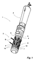
- An electric hair styling device 1 consists of a handle 2 and a hair brush 3.
- an electric hot air blower is arranged in the handle 2 .
- the handle 2 has air inlet openings at its rear end.
- the hot air blower itself comprises a fan and an electric heater, via which the air flow conveyed by the fan is led to its heating.
- an electric motor is arranged in the handle 2.
- the electric motor is used to drive the hairbrush 3, the torque-locking with the drive shaft of the electric motor, if necessary, geared stocky, is connected.
- the motor driven shaft on which the hairbrush 3 sits is in FIG. 1 denoted by the reference numeral 4.
- the shaft 4 is led out of the front-side outlet of the handle 2 axially.
- This front opening 5 of the handle 2 also serves as an air outlet opening for the funded by the handle 2 in the hot air flow.
- the shaft 4 itself is designed as a hollow shaft and has inlet openings 6, so that the conveyed by the hot air blower hot air stream can enter the interior of the hollow shaft 4. This serves the purpose that the hot air flow or a portion of the hot air flow is conveyed into an inner inflow channel of the hairbrush 3.
- This inflow channel is connected via air outlet openings 7 with the lateral surface 8 of the hairbrush 3, so that the air stream flowing into the inflow channel of the hairbrush 3 exit from the air outlet openings 7 and is fed to the hair to be formed.
- the hairbrush 3 is closed at its front, the shaft 4 opposite end.
- the hairbrush 3 consists of a substantially cylindrical shaft 9 with the lateral surface 8.
- the lateral surface 8 of the shaft 9 is formed in the illustrated embodiment by a sleeve 10 which, leaving an annular gap 11 (see. FIG. 2 ) concentrically encloses a tube core 12.
- the tube core 12 in turn, includes the above-described inlet channel 13 of the hairbrush 3.
- the sleeve 10 is based on the tubular core 12 integrally formed cylindrical extensions 14 from.
- the tube core 12 is used to anchor the bristle tufts B of the hairbrush 3.
- 12 anchoring holes 15 are introduced into the tube core, in which the bristle tufts B are set or anchored with her foot.
- the sleeve 10 has bristle openings 16 through which the bristle tufts B pass.
- the bristle openings 16 of the sleeve 10 have an inner width which is significantly larger than the diameter of an anchoring hole 15 provided for anchoring a bristle tuft B.
- each bristle tuft B can readily be reciprocated within a bristle opening 6.
- the individual bristles of the bristle tufts B are not compressed by the bristle opening 16.
- the contour of the brush openings 16 the contour of a slot, which extends in its longitudinal extent diagonal to the rotational movement of the hair brush 3, as this in FIG. 1 is recognizable.
- FIG. 1 only individual bristle tufts B are shown.
- the tube core 12 is torsionally connected to the shaft 4.
- the air flow conveyed by the hot air blower flows at least partially into the inflow channel 13 of the hair brush 12 and into the annular gap 11 formed by the sleeve 10. From the inflow passage 13, this hot air flow passes out of the hairbrush 3 through the air outlet openings 7 in the radial direction.
- the sleeve 10 In alignment with the air outlet openings 7 of the tube core 12, the sleeve 10 also has corresponding air outlet openings, wherein inside the annular gap 11, a mixing with the airflow conveyed in the annular gap 11 takes place and the heated air also exits from the bristle openings 16. The entrained by the hot air flow heat is thus fed directly to the hair to be formed.
- the bristle of the hairbrush 3 with respect to their density and the rigidity of the bristle tufts B is formed so that when rotating hairbrush 3 a rotational drive of the applied hairbrush 3 hair only over about 180 ° or something more.
- the sleeve 10 has a chrome-plated surface so that it is particularly smooth. Therefore, a rotary driving with rotating hairbrush 3 of hair does not take place when they rest only on the lateral surface 8 of the shaft 9.
- the spacing of the bristle tufts anchoring in the anchoring holes 15 of the tube core 12 from the lateral surface 8 of the shaft 9 has the result that the bristle tufts B have relatively soft properties as they pass through the bristle openings 16.
- the hair grabbed by the bristle tufts B do not jam between the individual bristles of a bristle tuft B, resulting in the conditional rotational movement of the hair when the hairbrush is rotating. Also, the bristle tufts B are hardly affected in terms of their compliance with rotating hairbrush 3 in the bristle openings 16, which supports the desired, only conditional entrainment effect of the hair to be formed.
- the hairbrush 3 is to be addressed as moderately bristled.
- shaping hair with this hair styling device 1 can be formed by the rotary driving of the hair through the hair brush 3 to only about 180 ° waves.
- the entrainment of the hair by the hairbrush 3 primarily serves the purpose of forming the desired waveform.
- the rotating hairbrush 3 therefore serves as a mold, the hair-shaping process being assisted by the heat brought about by the stream of hot air.
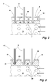
- FIG. 3 shows another hairbrush 17 for forming waves in the hair of a person, which is basically constructed as the hairbrush 3 of FIGS. 1 and 2 , In contrast to the hairbrush 3, however, the hairbrush 17 does not have an annular gap 11.
- the tube core 18 also includes an inflow 19, which is connected by air outlet openings 20 with the outer surface of the hair brush 17.
- the bristle tufts B are set in stepped, introduced radially into the tube core 18 holes 21, only the deepest portion serves as anchoring hole 22.
- the upper part of a hole 21 - the part 23 - serves as a distance opening whose inside diameter is greater than the diameter of the anchoring hole 22 in order to achieve the desired properties of the bristle tufts B.
- the lateral surface 24 of the hairbrush 17th is PTFE-coated. This coating is in FIG. 3 designated by the reference numeral 25.
- the coating 25 is responsible for the fact that no adhesion between the hair to be formed and the lateral surface 24 of the hairbrush 17, at least not appreciable, is present.
- the bristle tufts B react with rotating hairbrush 17 as well as the bristle tufts B of the previously described hairbrush 3.
- the electric hair styling device additionally has an ionization device in order to support the hair styling process by electron donation.
- an ionization device in order to support the hair styling process by electron donation.
- a second development can be provided to arrange the hair brush releasably on the motor-driven shaft, so that it can be replaced by a different diameter. Such a hairbrush is then designed as an attachment.
Abstract
Description
Die Erfindung betrifft ein elektrisches Haarformgerät zum Formen von Wellen mit einem in einem Griffstück integrierten Warmluftgebläse und mit einer elektromotorisch rotierend angetriebenen und von einem durch das Warmluftgebläse geförderten Luftstrom angeströmten Haarbürste mit einem Schaft und einer von dem Schaft abragenden Beborstung.The invention relates to an electric hair styling device for shaping waves with a built-in handle warm air blower and with an electric motor driven by a rotating and powered by the hot air blower air stream hairbrush with a shaft and a protruding from the shaft bristles.
Derartige Haarformgeräte dienen zum Formen von Locken in dem Haar einer Person. Dabei erfolgt ein Formen der Haare durch die elektromotorisch rotierend angetriebene Haarbürste, unterstützt von einem Warmluftstrom, der die zum Umformen benötigte Wärme an das umzuformende Haar bringt. Der Elektromotor sowie das Warmluftgebläse samt Heizeinrichtung sind typischerweise in einem rohrförmigen, als Griffstück dienenden Gehäuse untergebracht. Durch Eindrehen der Haarbürste in das umzuformende Haar bei rotierender Haarbürste werden die einzelnen Locken geformt. Eingerollt werden die zu einer Locke auszubildenden Haare infolge eine Drehmitnahme der von der Beborstung und/oder der Mantelfläche der Haarbürste ergriffenen Haare als Folge der Rotation der Haarbürste. Die umzuformenden Haare werden grundsätzlich von der in Drehung befindlichen Haarbürste über mehr als eine Haarbürstenumdrehung mitgenommen, was das vorbeschriebene Einrollen bzw. Eindrehen zur Folge hat. Die Haarbürste wird in das umzuformende Haar eingerollt wie ein Lockenwickler. Ein derartiges Haarformgerät ist beispielsweise aus
Bei einer Benutzung eines solchen Haarformgerätes ist darauf zu achten, dass der die Haarbürste antreibende Elektromotor rechtzeitig ausgeschaltet wird, bevor die Haarbürste in das zum Formen einer Locke vorgesehene Haarbüschel vollständig eingedreht wird, damit der durch die sich drehende Haarbürste auf das Haarbüschel wirkende Zug nicht zu groß und gegebenenfalls schmerzhaft wird. Um das auf die Haare einwirkende Drehmoment in einem solchen Fall zu begrenzen, ist die dem Elektromotor zugeführte elektrische Leistung dadurch begrenzt, dass die Stromversorgung des die Haarbürste antreibenden Elektromotors über einen Spannungsabgriff an der Heizeinrichtung realisiert ist.When using such a hair styling device, make sure that the electric motor driving the hairbrush is switched off in good time before the hairbrush is completely screwed into the hair tuft provided for shaping a curl, so that the pull acting on the tuft by the rotating hairbrush does not increase big and possibly painful. In order to limit the torque acting on the hair in such a case, the electric power supplied to the electric motor is limited by that Power supply of the hair brush driving electric motor is realized via a voltage tap on the heater.
Ein solches elektrisches Haarformgerät stellt eine Alternative zu einem Einsatz von Lockenwicklern dar. Mit diesem elektrischen Haarformgerät lassen sich jedoch keine Wellen ausbilden, wie dieses mitunter jedoch gewünscht wird. Sogenannte Fönwellen lassen sich herkömmlich nur mit einer Handbürste und einem Haartrockner formen, wobei es sehr viel Geschicklichkeit verlangt, Fönwellen auszubilden.Such an electric hair styling device is an alternative to a use of curlers. With this electric hair styling device, however, can not form waves, as this is sometimes desired. So-called hair drier waves can be formed conventionally only with a hand brush and a hair dryer, where it requires a lot of skill to train hair drier.
Ein elektrisches Haarformgerät zum Formen von Wellen, bei dem die zur Handhabung des vorbeschriebenen Gerätes aufgezeigten Nachteile vermieden sind, ist aus
Ausgehend von diesem diskutierten Stand der Technik liegt der Erfindung daher die Aufgabe zugrunde, ein eingangs genanntes elektrisches Haarformgerät dergestalt weiterzubilden, dass mit diesem Haarwellen, insbesondere sogenannte Föhnwellen ohne weiteres geformt werden können.Based on this discussed prior art, the invention is therefore the object of developing an aforementioned electric hair styling device such that with this hair waves, especially so-called hair dryer waves can be easily formed.
Diese Aufgabe wird erfindungsgemäß durch ein Haarformgerät gemäß Anspruch 1 gelöst.This object is achieved by a hair styling device according to
Bei diesem elektrischen Haarformgerät ist die Haarbürste dergestalt ausgebildet, dass eine Drehmitnahme auf das zu formende Haar nur soweit erfolgt, dass grundsätzlich ein vollständiges Eindrehen der Haarbürste in das zu formende Haar vermieden ist. Eine gewisse Drehmitnahme ist notwendig, um das zu formende Haar in eine die zu erstellende Welle nachbildenden Form für die zum Formen der Welle notwendigen Zeit zu halten. Die durch den Warmluftstrom bereitgestellte Wärme unterstützt den Haarformprozess, wobei zweckmäßigerweise die Haarbürste nach Art eines Airbrush ausgebildet ist und der die Haarbürste anströmende Warmluftstrom in einen inneren Einströmkanal der Haarbürste eintritt und aus diesem durch in der Haarbürste befindliche Luftaustrittsöffnungen in radialer Richtung herausgeführt ist.In this electric hair styling device, the hair brush is designed such that a rotational drive on the hair to be formed only to the extent that basically a complete screwing the hair brush is avoided in the hair to be formed. A certain rotational drive is necessary to keep the hair to be formed in a shape simulating the wave to be created for the necessary time for shaping the shaft. The heat provided by the warm air flow supports the hair-styling process, wherein the hairbrush is expediently designed in the manner of an airbrush and the hot air stream flowing into the hairbrush enters an inner inflow channel of the hairbrush and is led out of it through the air outlet openings located in the hairbrush in the radial direction.
Die vorbeschriebene bedingte Drehmitnahme der zu formenden Haare bei rotierender Haarbürste wird dadurch erreicht, dass die radial nach außen weisende Oberseite der Mantelfläche des Schaftes der Haarbürste eine solche Beschaffenheit aufweist, dass von dieser kein Drehmoment auf das zu formende Haar oder allenfalls nur ein vernachlässigbar kleines übertragen wird. Diese Oberfläche ist daher zweckmäßigerweise hoch glatt und/oder weist eine Beschichtung auf, an der das zu formende Haar bei rotierender Haarbürste nicht haftet, wie dieses beispielsweise bei einer Polytetrafluorethylen-Beschichtung (PTFE-Beschichtung) der Fall ist. Durch Ausbildung der Oberfläche des Schaftes der Haarbürste in dieser Art und Weise ist für eine Drehmitnahme der zu formenden Haare somit ausschließlich die Beborstung verantwortlich. Diese ist bezüglich ihrer Dichte und/oder ihrer Steifigkeit so konzipiert, dass einerseits zwar eine Drehmitnahme bei rotierender Haarbürste von zu formenden Haaren erfolgt, dass andererseits diese Drehmitnahme nur über einen Teil einer Haarbürstenumdrehung, beispielsweise über 180° erfolgt. Dadurch ist ein Eindrehen der rotierenden Haarbürste in das zu formende Haar wirksam verhindert. Zweckmäßig ist die Ausgestaltung einer Haarbürste, mit der eine Drehmitnahme des zu formenden Haares um 180° bis max. 270° erfolgt. Je nach Behandlungsdauer und Behandlungsart können mit einer solchen Haarbürste unterschiedlichste Haarwellen geformt werden.The above-described conditional rotational drive of the hair to be formed with a rotating hairbrush is achieved in that the radially outwardly facing top of the lateral surface of the shaft of the hairbrush has such a nature that transmitted from this no torque on the hair to be formed or at most only a negligibly small becomes. This surface is therefore expediently highly smooth and / or has a coating to which the hair to be formed does not adhere when the hairbrush is rotating, as is the case, for example, with a polytetrafluoroethylene coating (PTFE coating). By forming the surface of the shaft of the hairbrush in this manner is thus responsible for a rotational drive of the hair to be formed exclusively bristles. This is designed in terms of their density and / or their rigidity, that on the one hand, although a Rotational driving with rotating hair brush of hair to be formed takes place, on the other hand, this rotational drive takes place only over a part of a hair brush rotation, for example over 180 °. As a result, a screwing the rotating hair brush is effectively prevented in the hair to be formed. Appropriately, the embodiment of a hair brush, with a rotational drive of the hair to be formed by 180 ° to max. 270 ° takes place. Depending on the duration of treatment and type of treatment can be shaped with a hairbrush such a variety of hair waves.
Die Beborstung einer solchen Haarbürste wird hinsichtlich der Dichte ihrer Beborstung als mäßig geborstet angesprochen werden können. Die einzelnen Borstenbüschel selbst sind zweckmäßigerweise gegenüber der Mantelfläche des Haartrockners vertieft verankert, wobei vorgesehen ist, dass die eigentliche Verankerung des Fußes der Borstenbüschel von der Mantelfläche durch eine Abstandsöffnung beabstandet ist. Die nach Innen weisende Seite der Abstandsöffnung ist von der Mantelfläche eines Borstenbüschels beabstandet, so dass dieses innerhalb der Abstandsöffnung hin- und herbewegt werden kann. Die Abstandsöffnung dient dem Zweck, dass die Borstenbüschel bereits an der Oberseite der Mantelfläche des Schaftes der Haarbürste eine gewisse Weichheit bzw. Nachgiebigkeit aufweisen und in diesem Bereich nur noch lose aneinander liegen. Von einem solchen Borstenbüschel ergriffenes Haar kann dann, wenn es zur Mantelfläche des Haartrockners hingezogen wird auch zwischen den einzelnen Haaren eines Borstenbüschels hindurchgleiten, ohne zwischen den einzelnen Borstenhaaren verklemmt zu werden.The bristles of such a hairbrush may be considered moderately bristled in terms of the density of their bristles. The individual bristle tufts themselves are expediently recessed in relation to the jacket surface of the hair dryer, it being provided that the actual anchoring of the foot of the bristle tufts is spaced from the lateral surface by a spacing opening. The inwardly facing side of the spacer opening is spaced from the lateral surface of a bristle tuft so that it can be reciprocated within the spacer opening. The distance opening serves the purpose that the bristle tufts already at the top of the lateral surface of the shank of the hairbrush have a certain softness or compliance and in this area are only loosely together. Hair gripped by such a bristle tuft, when attracted to the surface of the hair dryer, may also slide between the individual hairs of a bristle tuft without being jammed between the individual bristle hairs.
Die für die Nachgiebigkeit der Borstenbüschel im Bereich der Mantelfläche des Haartrockners verantwortliche Abstandsöffnung kann von unterschiedlicher Geometrie sein. Die Abstandsöffnung kann beispielsweise eine Öffnung kreisrunden Querschnittes sein. Ebenso ist es möglich, die Abstandsöffnung als Langloch zu konzipieren, wobei bei einer solchen Ausgestaltung zweckmäßigerweise die Längserstreckung des Langloches zumindest einen in Drehrichtung der Haarbürste weisenden Anteil aufweist. Dieses ist beispielsweise bei einem Langloch der Fall, dessen Langsachse in Drehrichtung der Haarbürste weist oder dessen Langachse in einer diagonalen Richtung dazu ausgerichtet ist.The clearance opening responsible for the compliance of the bristle tufts in the region of the jacket surface of the hair dryer may be of different geometry. The distance opening may be, for example, an opening of circular cross-section. It is also possible to design the distance opening as a slot, wherein in such a configuration, the longitudinal extent of the elongated hole expediently has at least one portion pointing in the direction of rotation of the hairbrush. This is the case, for example, in the case of a slot whose longitudinal axis points in the direction of rotation of the hairbrush or whose longitudinal axis is aligned in a diagonal direction.
Die Abstandsöffnung kann unmittelbar an ein Verankerungsloch zum Verankern eines Borstenbüschels angrenzen, wodurch ein gestuftes Loch ausgebildet ist. Gemäß einer weiteren Ausgestaltung ist vorgesehen, dass die Borstenbüschel in einem Rohrkern verankert sind, das von einer konzentrisch den Rohrkern einschließenden Hülse eingeschlossen ist. Die Außenseite der Hülse bildet sodann die Oberseite der Mantelfläche der Haarbürste. Die Hülse kann außenseitig beispielsweise eine verchromte und somit hoch glatte Oberfläche aufweisen. Diese Hülse weist Borstenöffnungen in der Kontur der vorgesehenen Abstandsöffnungen auf. Gemäß einer Ausgestaltung ist vorgesehen, eine solche Hülse mit Abstand zum Rohrkern anzuordnen, wodurch ein Ringspalt zwischen dem Rohrkern und der Hülse vorgesehen ist. Der Ringspalt dient zum einen zum Beabstanden des Borstenaustrittes aus ihren Verankerungslöchern und der Mantelfläche des durch die Hülse gebildeten Schaftes. Zum anderen dient dieser zum Leiten eines Luftstromes, der sodann durch die als Abstandsöffnungen dienenden Borstenöffnungen der Hülse dem umzuformenden Haar zugeführt wird.The spacing opening may directly adjoin an anchoring hole for anchoring a bristle tuft, whereby a stepped hole is formed. According to a further embodiment it is provided that the bristle tufts are anchored in a tube core, which is enclosed by a concentrically enclosing the tube core sleeve. The outside of the sleeve then forms the top of the lateral surface of the hairbrush. The sleeve may have on the outside, for example, a chrome-plated and thus highly smooth surface. This sleeve has bristle openings in the contour of the provided spacing openings. According to one embodiment, it is provided to arrange such a sleeve at a distance from the tube core, whereby an annular gap between the tube core and the sleeve is provided. The annular gap is used firstly for spacing the bristle outlet from its anchoring holes and for the lateral surface of the shank formed by the sleeve. On the other hand, this serves to conduct an air flow, which is then supplied through the serving as clearance openings bristle openings of the sleeve to the reshaped hair.
Da bei diesem elektrischen Haarformgerät ein Eindrehen der Haarbürste in das zu formende Haar bei bestimmungsgemäßem Einsatz nicht möglich ist, kann die Leistung des Elektromotors stärker ausgelegt sein. Dieses erfolgt zweckmäßigerweise dadurch, dass der Elektromotor nicht über einen Spannungsabgriff an die Heizeinrichtung des Warmluftgebläses angeschlossen ist, sondern dass das Haarformgerät einen eigenen Stromanschluss für den zum Drehen der Haarbürste eingesetzten Elektromotor aufweist, beispielsweise einen Transformator. Es ist dann möglich, die Haarbürste auch mit einer höheren Drehgeschwindigkeit anzutreiben, vor allem auch ohne eine Einbuße hinsichtlich der Leistungsfähigkeit der Heizeinrichtung hinnehmen zu müssen.Since in this electric hair styling device screwing the hairbrush into the hair to be formed in normal use is not possible, the performance of the electric motor can be designed stronger. This is advantageously carried out in that the electric motor is not connected via a voltage tap to the heater of the hot air blower, but that the hair styling device has its own power connector for the electric motor used to rotate the hairbrush, such as a transformer. It is then possible to drive the hairbrush with a higher rotational speed, especially without having to accept a loss in terms of the performance of the heater.
Nachfolgend ist die Erfindung anhand von Ausführungsbeispielen unter Bezugnahme auf die beigefügten Figuren beschrieben. Es zeigen:
- Fig. 1:
- eine schematisierte perspektivische Ansicht eines elektrischen Haarformgerätes mit einer rotierend angetriebenen Haarbürste,
- Fig. 2:
- einen Ausschnitt eines vergrößerten Längsschnittes durch die Haarbürste der
Figur 1 - Fig. 3:
- einen Ausschnitt eines Längsschnittes durch eine Haarbürste gemäß einem weiteren Ausführungsbeispiel eines elektrischen Haarformgerätes.
- Fig. 1:
- a schematic perspective view of an electric hair styling device with a rotary driven hair brush,
- Fig. 2:
- a section of an enlarged longitudinal section through the Hairbrush the
FIG. 1 and - 3:
- a section of a longitudinal section through a hair brush according to another embodiment of an electric hair styling device.
Ein elektrisches Haarformgerät 1 besteht aus einem Griffstück 2 und einer Haarbürste 3. In dem Griffstück 2 ist ein elektrisches Warmluftgebläse angeordnet. Zu diesem Zweck weist das Griffstück 2 an seinem hinteren Ende Lufteinlassöffnungen auf. Das Warmluftgebläse selbst umfasst einen Lüfter sowie eine elektrische Heizeinrichtung, über die der von dem Lüfter geförderter Luftstrom zu seiner Erwärmung geführt wird. Ferner ist in dem Griffstück 2 ein Elektromotor angeordnet. Der Elektromotor dient zum Antreiben der Haarbürste 3, die drehmomentschlüssig mit der Antriebswelle des Elektromotors, gegebenenfalls getrieblich untersetzt, verbunden ist. Die motorisch angetriebene Welle, auf der die Haarbürste 3 aufsitzt, ist in
Die Haarbürste 3 besteht aus einem im Wesentlichen zylindrischen Schaft 9 mit der Mantelfläche 8. Die Mantelfläche 8 des Schaftes 9 wird bei dem dargestellten Ausführungsbeispiel durch eine Hülse 10 gebildet, die unter Belassung eines Ringspaltes 11 (vgl.
Der Rohrkern 12 dient zum Verankern der Borstenbüschel B der Haarbürste 3. Zu diesem Zweck sind in den Rohrkern 12 Verankerungslöcher 15 eingebracht, in die die Borstenbüschel B mit ihrem Fuße festgesetzt bzw. verankert sind. Die Hülse 10 weist Borstenöffnungen 16 auf, durch die die Borstenbüschel B hindurchtreten. Die Borstenöffnungen 16 der Hülse 10 weisen eine innere Weite auf, die deutlich größer ist als der Durchmesser eines zum Verankern eines Borstenbüschels B vorgesehenen Verankerungsloches 15. Somit kann jedes Borstenbüschel B innerhalb einer Borstenöffnung 6 ohne weiteres hin- und herbewegt werden. Insbesondere werden die einzelnen Borsten des Borstenbüschels B durch die Borstenöffnung 16 nicht zusammengedrückt. Bei dem dargestellten Ausführungsbeispiel weist die Kontur der Bürstenöffnungen 16 die Kontur eines Langloches auf, das in seiner Längserstreckung diagonal zur Drehbewegung der Haarbürste 3 verläuft, wie dieses in
Der Rohrkern 12 ist drehmomentschlüssig mit der Welle 4 verbunden.The
Bei einem Betrieb des elektrischen Haarformgerätes 1 zum Formen einer Locke strömt der von dem Warmluftgebläse geförderte Luftstrom zumindest anteilig in den Einströmkanal 13 der Haarbürste 12 sowie in den durch die Hülse 10 gebildeten Ringspalt 11 ein. Aus dem Einströmkanal 13 tritt dieser Warmluftstrom durch die Luftaustrittsöffnungen 7 in radialer Richtung aus der Haarbürste 3 heraus. Fluchtend mit den Luftaustrittsöffnungen 7 des Rohrkerns 12 weist auch die Hülse 10 entsprechende Luftaustrittsöffnungen auf, wobei innerhalb des Ringspaltes 11 eine Vermischung mit dem in dem Ringspalt 11 geförderten Luftstrom erfolgt und die erwärmte Luft auch aus den Borstenöffnungen 16 austritt. Die durch den Warmluftstrom mitgeführte Wärme wird somit unmittelbar dem zu formenden Haar zugeführt.During operation of the electric
Die Beborstung der Haarbürste 3 hinsichtlich ihrer Dichte und der Steifigkeit der Borstenbüschel B ist ausgebildet, damit bei rotierender Haarbürste 3 eine Drehmitnahme des an der Haarbürste 3 anliegenden Haars nur über etwa 180° oder etwas mehr erfolgt. Aus diesem Grunde weist die Hülse 10 eine verchromte Oberfläche auf, damit diese besonders glatt ist. Daher erfolgt eine Drehmitnahme bei rotierender Haarbürste 3 von Haaren nicht, wenn diese lediglich an der Mantelfläche 8 des Schaftes 9 anliegen. Die Beabstandung der Borstenbüschelverankerung in den Verankerungslöchern 15 des Rohrkerns 12 von der Mantelfläche 8 des Schaftes 9 hat zur Folge, dass die Borstenbüschel B bei ihrem Durchtritt durch die Borstenöffnungen 16 relativ weiche Eigenschaften aufweisen. Daher verklemmen die von den Borstenbüscheln B ergriffenen Haare nicht zwischen den einzelnen Borsten eines Borstenbüschels B, was die bedingte Drehmitnahme der Haare bei rotierender Haarbürste zur Folge hat. Auch sind die Borstenbüschel B hinsichtlich ihrer Nachgiebigkeit bei rotierender Haarbürste 3 in den Borstenöffnungen 16 kaum beeinträchtigt, was den gewünschten, nur bedingten Mitnahmeeffekt des zu formenden Haares unterstützt. Die Haarbürste 3 ist insgesamt als mäßig beborstet anzusprechen.The bristle of the
Beim Formen von Haaren mit diesem Haarformgerät 1 können durch die Drehmitnahme der Haare durch die Haarbürste 3 um lediglich etwa 180° Wellen geformt werden. Dabei dient die Mitnahme der Haare durch die Haarbürste 3 vornehmlich dem Zweck, die gewünschte Wellenform auszubilden. Die rotierende Haarbürste 3 dient daher als Formwerkzeug, wobei der Haarformprozess von der durch den Warmluftstrom herangeführten Wärme unterstützt wird.When shaping hair with this
In einer ersten Weiterbildung ist vorgesehen, dass das elektrische Haarformgerät zusätzlich über eine lonisierungseinrichtung verfügt, um den Haarformprozess durch Elektronenabgabe zu unterstützen. Als zweite Weiterbildung kann vorgesehen sein, die Haarbürste lösbar auf der motorisch angetriebenen Welle anzuordnen, so dass diese durch eine im Durchmesser unterschiedliche ausgetauscht werden kann. Eine solche Haarbürste ist sodann als Aufsatz konzipiert.In a first development it is provided that the electric hair styling device additionally has an ionization device in order to support the hair styling process by electron donation. As a second development can be provided to arrange the hair brush releasably on the motor-driven shaft, so that it can be replaced by a different diameter. Such a hairbrush is then designed as an attachment.
- 11
- HaarformgerätThe hair styling appliance
- 22
- Griffstückgrip
- 33
- Haarbürstehairbrush
- 44
- Wellewave
- 55
- Öffnungopening
- 66
- Einströmöffnunginflow
- 77
- LuftaustrittsöffnungAir outlet opening
- 88th
- Mantelflächelateral surface
- 99
- Schaftshaft
- 1010
- Hülseshell
- 1111
- Ringspaltannular gap
- 1212
- Rohrkerntube core
- 1313
- Einströmkanalinflow
- 1414
- Fortsatzextension
- 1515
- Verankerungslochanchoring hole
- 1616
- Bürstenöffnungbrush opening
- 1717
- Haarbürstehairbrush
- 1919
- Rohrkerntube core
- 1919
- Einströmkanalinflow
- 2020
- LuftaustrittsöffnungAir outlet opening
- 2121
- Lochhole
- 2222
- Verankerungslochanchoring hole
- 2323
- Abstandsöffnungdistance opening
- 2424
- Mantelflächelateral surface
- 2525
- PTFE-BeschichtungPTFE coating
- BB
- Borstenbüscheltufts
Claims (8)
Applications Claiming Priority (2)
| Application Number | Priority Date | Filing Date | Title |
|---|---|---|---|
| DE200420004200 DE202004004200U1 (en) | 2004-03-16 | 2004-03-16 | Electric hair styling device |
| EP20050101900 EP1576900B1 (en) | 2004-03-16 | 2005-03-11 | Electrically driven and heated hair brush |
Related Parent Applications (2)
| Application Number | Title | Priority Date | Filing Date |
|---|---|---|---|
| EP20050101900 Division EP1576900B1 (en) | 2004-03-16 | 2005-03-11 | Electrically driven and heated hair brush |
| EP05101900.8 Division | 2005-03-11 |
Publications (2)
| Publication Number | Publication Date |
|---|---|
| EP2074902A1 true EP2074902A1 (en) | 2009-07-01 |
| EP2074902B1 EP2074902B1 (en) | 2010-08-18 |
Family
ID=34833330
Family Applications (2)
| Application Number | Title | Priority Date | Filing Date |
|---|---|---|---|
| EP09100216A Expired - Fee Related EP2074902B1 (en) | 2004-03-16 | 2005-03-11 | Electrically driven and heated hair brush |
| EP20050101900 Expired - Fee Related EP1576900B1 (en) | 2004-03-16 | 2005-03-11 | Electrically driven and heated hair brush |
Family Applications After (1)
| Application Number | Title | Priority Date | Filing Date |
|---|---|---|---|
| EP20050101900 Expired - Fee Related EP1576900B1 (en) | 2004-03-16 | 2005-03-11 | Electrically driven and heated hair brush |
Country Status (4)
| Country | Link |
|---|---|
| EP (2) | EP2074902B1 (en) |
| JP (1) | JP3111459U (en) |
| CN (1) | CN2891771Y (en) |
| DE (3) | DE202004004200U1 (en) |
Cited By (3)
| Publication number | Priority date | Publication date | Assignee | Title |
|---|---|---|---|---|
| EP2428132A1 (en) * | 2010-09-09 | 2012-03-14 | WIK Far East Ltd | Hair brush with retractable bristles |
| WO2023001980A1 (en) | 2021-07-22 | 2023-01-26 | L'oreal | Brush for treating the hair |
| WO2023001983A1 (en) | 2021-07-22 | 2023-01-26 | L’Oreal | Brush and method for treating the hair |
Families Citing this family (10)
| Publication number | Priority date | Publication date | Assignee | Title |
|---|---|---|---|---|
| ES2265286B1 (en) * | 2005-07-18 | 2007-12-01 | Dols Industrial De Peluqueria, S.A. | "HAIR BRUSH". |
| FR2914543B1 (en) | 2007-04-06 | 2010-02-26 | Seb Sa | ELECTRIC HAIR BRUSH |
| GB2461291A (en) * | 2008-06-26 | 2009-12-30 | Ricky Moate | Brush |
| CN203591004U (en) * | 2011-01-17 | 2014-05-14 | 新联电器厂有限公司 | Hair styling apparatus |
| CN202456955U (en) * | 2012-02-16 | 2012-10-03 | 建福实业有限公司 | Hair combing device |
| CN103763973B (en) * | 2012-04-23 | 2017-02-22 | 新联电器厂有限公司 | Accessory for hair styling apparatus |
| CN104720257A (en) * | 2013-12-23 | 2015-06-24 | 王圣君 | Electric heating hair curling and air blowing device |
| CN103932478A (en) * | 2014-03-28 | 2014-07-23 | 莱富利美容工具(张家港)有限公司 | Eyelash perming device |
| EP3459386A1 (en) | 2017-09-22 | 2019-03-27 | BaByliss Faco sprl | Rotary blower brush with improved ergonomics |
| BR112020003434A2 (en) | 2017-09-01 | 2020-08-25 | Babyliss Faco Sprl | rotary dryer brush |
Citations (7)
| Publication number | Priority date | Publication date | Assignee | Title |
|---|---|---|---|---|
| US3890984A (en) * | 1974-01-23 | 1975-06-24 | Alexander C Lesetar | Hair dryer with rotary brush |
| US3894549A (en) | 1973-01-12 | 1975-07-15 | Malibu Personal Beauty Product | Electrically driven and heated hair treating device |
| US4023578A (en) | 1974-11-08 | 1977-05-17 | Etablissements Lardenois | Blow-wave brush |
| GB2007500A (en) * | 1977-11-11 | 1979-05-23 | Braun Ag | Hair brush |
| DE3529267A1 (en) | 1985-08-16 | 1987-02-26 | Schuermann Hans Peter | Hair-dryer/curling tongs having a rotatable round brush |
| JPH1052311A (en) * | 1996-08-09 | 1998-02-24 | Takahashi Michiko | Curl rotating system for hair drier |
| US6363215B1 (en) * | 2000-06-12 | 2002-03-26 | Helen Of Troy, L.P. | Hot air and light emitting curling brush |
-
2004
- 2004-03-16 DE DE200420004200 patent/DE202004004200U1/en not_active Expired - Lifetime
-
2005
- 2005-03-11 DE DE200550010120 patent/DE502005010120D1/en active Active
- 2005-03-11 EP EP09100216A patent/EP2074902B1/en not_active Expired - Fee Related
- 2005-03-11 DE DE200550007733 patent/DE502005007733D1/en active Active
- 2005-03-11 EP EP20050101900 patent/EP1576900B1/en not_active Expired - Fee Related
- 2005-03-16 CN CNU2005200084022U patent/CN2891771Y/en not_active Expired - Lifetime
- 2005-03-16 JP JP2005001369U patent/JP3111459U/en not_active Expired - Lifetime
Patent Citations (7)
| Publication number | Priority date | Publication date | Assignee | Title |
|---|---|---|---|---|
| US3894549A (en) | 1973-01-12 | 1975-07-15 | Malibu Personal Beauty Product | Electrically driven and heated hair treating device |
| US3890984A (en) * | 1974-01-23 | 1975-06-24 | Alexander C Lesetar | Hair dryer with rotary brush |
| US4023578A (en) | 1974-11-08 | 1977-05-17 | Etablissements Lardenois | Blow-wave brush |
| GB2007500A (en) * | 1977-11-11 | 1979-05-23 | Braun Ag | Hair brush |
| DE3529267A1 (en) | 1985-08-16 | 1987-02-26 | Schuermann Hans Peter | Hair-dryer/curling tongs having a rotatable round brush |
| JPH1052311A (en) * | 1996-08-09 | 1998-02-24 | Takahashi Michiko | Curl rotating system for hair drier |
| US6363215B1 (en) * | 2000-06-12 | 2002-03-26 | Helen Of Troy, L.P. | Hot air and light emitting curling brush |
Cited By (5)
| Publication number | Priority date | Publication date | Assignee | Title |
|---|---|---|---|---|
| EP2428132A1 (en) * | 2010-09-09 | 2012-03-14 | WIK Far East Ltd | Hair brush with retractable bristles |
| WO2023001980A1 (en) | 2021-07-22 | 2023-01-26 | L'oreal | Brush for treating the hair |
| WO2023001983A1 (en) | 2021-07-22 | 2023-01-26 | L’Oreal | Brush and method for treating the hair |
| FR3125398A1 (en) | 2021-07-22 | 2023-01-27 | L'oreal | Hair treatment brush and method |
| FR3125400A1 (en) | 2021-07-22 | 2023-01-27 | L'oreal | hair treatment brush |
Also Published As
| Publication number | Publication date |
|---|---|
| DE202004004200U1 (en) | 2005-08-11 |
| JP3111459U (en) | 2005-07-28 |
| EP1576900A1 (en) | 2005-09-21 |
| DE502005010120D1 (en) | 2010-09-30 |
| DE502005007733D1 (en) | 2009-09-03 |
| CN2891771Y (en) | 2007-04-25 |
| EP1576900B1 (en) | 2009-07-22 |
| EP2074902B1 (en) | 2010-08-18 |
Similar Documents
| Publication | Publication Date | Title |
|---|---|---|
| EP1576900B1 (en) | Electrically driven and heated hair brush | |
| DE112013004159B4 (en) | Directional nozzle attachment | |
| DE60319890T2 (en) | Hair dryer with a minus ion generator | |
| DE60211015T2 (en) | HAIR CARE INSTRUMENTS AND DEVICES | |
| EP0610412B1 (en) | Diffuser for a hair-dryer | |
| DE4243640C2 (en) | Tool for hair styling / drying for an air-flow device for personal needs | |
| DE202008018013U1 (en) | Electric hairbrush | |
| EP1425986A1 (en) | Brush for hair styling and shaping | |
| DE2409019C2 (en) | Hand held hair dryer | |
| DE202004007437U1 (en) | Device for dyeing hair | |
| WO1993016617A1 (en) | Mascara brush | |
| DE2051419A1 (en) | Device for curling hair using curlers and hot air | |
| DE2502821A1 (en) | Electric hair dryer with electrically driven comb - for use by professional hairdressers and in home has exchangeable comb on hexagonal hollow shaft | |
| US6823874B2 (en) | Hair curling comb device | |
| WO2001015568A1 (en) | Brush attachment for a hand-held device diffusing hot air | |
| EP1672965A1 (en) | Hair-care applicance with an ion generator device | |
| EP2533664B1 (en) | Attachment for a hairstyling apparatus | |
| DE2526637C2 (en) | hairbrush | |
| DE60316605T2 (en) | NOZZLE FOR A HAIR DRYER | |
| WO1995004485A1 (en) | Hair-care process and device | |
| EP0043907B1 (en) | Apparatus for dressing and taking care of the hair | |
| DE2526374A1 (en) | A BRUSH FLOWED BY A HOT AIR FLOW FOR HAIR CARE | |
| EP2827736B1 (en) | Hair styling device and method for treating a hair strand | |
| DE2825099A1 (en) | Hair curler for attachment to hair dryer - has conical fitment for attachment and radial bristles adjustable by rod inside sleeve | |
| DE2501682A1 (en) | Hairdressing system with hot air blower - uses comb or brush arrangement geared to blower motor for rotation |
Legal Events
| Date | Code | Title | Description |
|---|---|---|---|
| PUAI | Public reference made under article 153(3) epc to a published international application that has entered the european phase |
Free format text: ORIGINAL CODE: 0009012 |
|
| AC | Divisional application: reference to earlier application |
Ref document number: 1576900 Country of ref document: EP Kind code of ref document: P |
|
| AK | Designated contracting states |
Kind code of ref document: A1 Designated state(s): DE FR GB GR IT |
|
| RIN1 | Information on inventor provided before grant (corrected) |
Inventor name: BOUQUET, ERIC Inventor name: HAFEMANN, KLAUS |
|
| 17P | Request for examination filed |
Effective date: 20091223 |
|
| AKX | Designation fees paid |
Designated state(s): DE FR GB GR IT |
|
| 17Q | First examination report despatched |
Effective date: 20100224 |
|
| GRAP | Despatch of communication of intention to grant a patent |
Free format text: ORIGINAL CODE: EPIDOSNIGR1 |
|
| GRAS | Grant fee paid |
Free format text: ORIGINAL CODE: EPIDOSNIGR3 |
|
| GRAA | (expected) grant |
Free format text: ORIGINAL CODE: 0009210 |
|
| AC | Divisional application: reference to earlier application |
Ref document number: 1576900 Country of ref document: EP Kind code of ref document: P |
|
| AK | Designated contracting states |
Kind code of ref document: B1 Designated state(s): DE FR GB GR IT |
|
| REG | Reference to a national code |
Ref country code: GB Ref legal event code: FG4D Free format text: NOT ENGLISH |
|
| REF | Corresponds to: |
Ref document number: 502005010120 Country of ref document: DE Date of ref document: 20100930 Kind code of ref document: P |
|
| PG25 | Lapsed in a contracting state [announced via postgrant information from national office to epo] |
Ref country code: GR Free format text: LAPSE BECAUSE OF FAILURE TO SUBMIT A TRANSLATION OF THE DESCRIPTION OR TO PAY THE FEE WITHIN THE PRESCRIBED TIME-LIMIT Effective date: 20101119 |
|
| PLBE | No opposition filed within time limit |
Free format text: ORIGINAL CODE: 0009261 |
|
| STAA | Information on the status of an ep patent application or granted ep patent |
Free format text: STATUS: NO OPPOSITION FILED WITHIN TIME LIMIT |
|
| 26N | No opposition filed |
Effective date: 20110519 |
|
| PGFP | Annual fee paid to national office [announced via postgrant information from national office to epo] |
Ref country code: GB Payment date: 20110324 Year of fee payment: 7 |
|
| REG | Reference to a national code |
Ref country code: DE Ref legal event code: R097 Ref document number: 502005010120 Country of ref document: DE Effective date: 20110519 |
|
| GBPC | Gb: european patent ceased through non-payment of renewal fee |
Effective date: 20120311 |
|
| PG25 | Lapsed in a contracting state [announced via postgrant information from national office to epo] |
Ref country code: GB Free format text: LAPSE BECAUSE OF NON-PAYMENT OF DUE FEES Effective date: 20120311 |
|
| REG | Reference to a national code |
Ref country code: FR Ref legal event code: PLFP Year of fee payment: 12 |
|
| REG | Reference to a national code |
Ref country code: FR Ref legal event code: PLFP Year of fee payment: 13 |
|
| REG | Reference to a national code |
Ref country code: FR Ref legal event code: CA Effective date: 20170518 |
|
| REG | Reference to a national code |
Ref country code: FR Ref legal event code: PLFP Year of fee payment: 14 |
|
| PGFP | Annual fee paid to national office [announced via postgrant information from national office to epo] |
Ref country code: DE Payment date: 20180209 Year of fee payment: 14 |
|
| PGFP | Annual fee paid to national office [announced via postgrant information from national office to epo] |
Ref country code: FR Payment date: 20180326 Year of fee payment: 14 Ref country code: IT Payment date: 20180322 Year of fee payment: 14 |
|
| REG | Reference to a national code |
Ref country code: DE Ref legal event code: R119 Ref document number: 502005010120 Country of ref document: DE |
|
| PG25 | Lapsed in a contracting state [announced via postgrant information from national office to epo] |
Ref country code: DE Free format text: LAPSE BECAUSE OF NON-PAYMENT OF DUE FEES Effective date: 20191001 |
|
| PG25 | Lapsed in a contracting state [announced via postgrant information from national office to epo] |
Ref country code: IT Free format text: LAPSE BECAUSE OF NON-PAYMENT OF DUE FEES Effective date: 20190311 Ref country code: FR Free format text: LAPSE BECAUSE OF NON-PAYMENT OF DUE FEES Effective date: 20190331 |