EP2074831B1 - Projection avec un écran zscreen ® double - Google Patents
Projection avec un écran zscreen ® double Download PDFInfo
- Publication number
- EP2074831B1 EP2074831B1 EP07839482.2A EP07839482A EP2074831B1 EP 2074831 B1 EP2074831 B1 EP 2074831B1 EP 07839482 A EP07839482 A EP 07839482A EP 2074831 B1 EP2074831 B1 EP 2074831B1
- Authority
- EP
- European Patent Office
- Prior art keywords
- projector
- images
- image
- field
- transmitted
- Prior art date
- Legal status (The legal status is an assumption and is not a legal conclusion. Google has not performed a legal analysis and makes no representation as to the accuracy of the status listed.)
- Active
Links
- 230000009977 dual effect Effects 0.000 title description 7
- 238000000034 method Methods 0.000 claims description 18
- 230000010287 polarization Effects 0.000 claims description 6
- 230000000295 complement effect Effects 0.000 claims 2
- 230000005540 biological transmission Effects 0.000 claims 1
- 238000005286 illumination Methods 0.000 description 27
- 238000013461 design Methods 0.000 description 23
- 230000002123 temporal effect Effects 0.000 description 17
- 230000035807 sensation Effects 0.000 description 11
- 238000013459 approach Methods 0.000 description 8
- 230000000694 effects Effects 0.000 description 7
- 208000003464 asthenopia Diseases 0.000 description 5
- 230000008901 benefit Effects 0.000 description 4
- 230000004927 fusion Effects 0.000 description 3
- 239000000463 material Substances 0.000 description 3
- 230000003287 optical effect Effects 0.000 description 3
- 230000008447 perception Effects 0.000 description 3
- 230000002688 persistence Effects 0.000 description 3
- 206010019233 Headaches Diseases 0.000 description 2
- 239000000654 additive Substances 0.000 description 2
- 230000000996 additive effect Effects 0.000 description 2
- 238000010586 diagram Methods 0.000 description 2
- 230000006870 function Effects 0.000 description 2
- 231100000869 headache Toxicity 0.000 description 2
- 230000001360 synchronised effect Effects 0.000 description 2
- 230000000007 visual effect Effects 0.000 description 2
- 208000002193 Pain Diseases 0.000 description 1
- 230000006978 adaptation Effects 0.000 description 1
- 230000009286 beneficial effect Effects 0.000 description 1
- 230000008859 change Effects 0.000 description 1
- 230000001186 cumulative effect Effects 0.000 description 1
- 230000001747 exhibiting effect Effects 0.000 description 1
- 238000003384 imaging method Methods 0.000 description 1
- 238000009434 installation Methods 0.000 description 1
- 238000012986 modification Methods 0.000 description 1
- 230000004048 modification Effects 0.000 description 1
- 238000012544 monitoring process Methods 0.000 description 1
- 230000003387 muscular Effects 0.000 description 1
- 230000000926 neurological effect Effects 0.000 description 1
- 230000037361 pathway Effects 0.000 description 1
- 230000008569 process Effects 0.000 description 1
- 230000001629 suppression Effects 0.000 description 1
- 230000009466 transformation Effects 0.000 description 1
Images


Classifications
-
- H—ELECTRICITY
- H04—ELECTRIC COMMUNICATION TECHNIQUE
- H04N—PICTORIAL COMMUNICATION, e.g. TELEVISION
- H04N13/00—Stereoscopic video systems; Multi-view video systems; Details thereof
-
- G—PHYSICS
- G03—PHOTOGRAPHY; CINEMATOGRAPHY; ANALOGOUS TECHNIQUES USING WAVES OTHER THAN OPTICAL WAVES; ELECTROGRAPHY; HOLOGRAPHY
- G03B—APPARATUS OR ARRANGEMENTS FOR TAKING PHOTOGRAPHS OR FOR PROJECTING OR VIEWING THEM; APPARATUS OR ARRANGEMENTS EMPLOYING ANALOGOUS TECHNIQUES USING WAVES OTHER THAN OPTICAL WAVES; ACCESSORIES THEREFOR
- G03B35/00—Stereoscopic photography
- G03B35/18—Stereoscopic photography by simultaneous viewing
-
- H—ELECTRICITY
- H04—ELECTRIC COMMUNICATION TECHNIQUE
- H04N—PICTORIAL COMMUNICATION, e.g. TELEVISION
- H04N13/00—Stereoscopic video systems; Multi-view video systems; Details thereof
- H04N13/10—Processing, recording or transmission of stereoscopic or multi-view image signals
- H04N13/106—Processing image signals
- H04N13/144—Processing image signals for flicker reduction
-
- H—ELECTRICITY
- H04—ELECTRIC COMMUNICATION TECHNIQUE
- H04N—PICTORIAL COMMUNICATION, e.g. TELEVISION
- H04N13/00—Stereoscopic video systems; Multi-view video systems; Details thereof
- H04N13/30—Image reproducers
- H04N13/302—Image reproducers for viewing without the aid of special glasses, i.e. using autostereoscopic displays
- H04N13/31—Image reproducers for viewing without the aid of special glasses, i.e. using autostereoscopic displays using parallax barriers
- H04N13/315—Image reproducers for viewing without the aid of special glasses, i.e. using autostereoscopic displays using parallax barriers the parallax barriers being time-variant
-
- H—ELECTRICITY
- H04—ELECTRIC COMMUNICATION TECHNIQUE
- H04N—PICTORIAL COMMUNICATION, e.g. TELEVISION
- H04N13/00—Stereoscopic video systems; Multi-view video systems; Details thereof
- H04N13/30—Image reproducers
- H04N13/332—Displays for viewing with the aid of special glasses or head-mounted displays [HMD]
- H04N13/337—Displays for viewing with the aid of special glasses or head-mounted displays [HMD] using polarisation multiplexing
-
- H—ELECTRICITY
- H04—ELECTRIC COMMUNICATION TECHNIQUE
- H04N—PICTORIAL COMMUNICATION, e.g. TELEVISION
- H04N13/00—Stereoscopic video systems; Multi-view video systems; Details thereof
- H04N13/30—Image reproducers
- H04N13/332—Displays for viewing with the aid of special glasses or head-mounted displays [HMD]
- H04N13/341—Displays for viewing with the aid of special glasses or head-mounted displays [HMD] using temporal multiplexing
-
- H—ELECTRICITY
- H04—ELECTRIC COMMUNICATION TECHNIQUE
- H04N—PICTORIAL COMMUNICATION, e.g. TELEVISION
- H04N13/00—Stereoscopic video systems; Multi-view video systems; Details thereof
- H04N13/30—Image reproducers
- H04N13/363—Image reproducers using image projection screens
-
- H—ELECTRICITY
- H04—ELECTRIC COMMUNICATION TECHNIQUE
- H04N—PICTORIAL COMMUNICATION, e.g. TELEVISION
- H04N13/00—Stereoscopic video systems; Multi-view video systems; Details thereof
- H04N13/30—Image reproducers
- H04N13/398—Synchronisation thereof; Control thereof
-
- H—ELECTRICITY
- H04—ELECTRIC COMMUNICATION TECHNIQUE
- H04N—PICTORIAL COMMUNICATION, e.g. TELEVISION
- H04N5/00—Details of television systems
- H04N5/74—Projection arrangements for image reproduction, e.g. using eidophor
-
- H—ELECTRICITY
- H04—ELECTRIC COMMUNICATION TECHNIQUE
- H04N—PICTORIAL COMMUNICATION, e.g. TELEVISION
- H04N2213/00—Details of stereoscopic systems
- H04N2213/002—Eyestrain reduction by processing stereoscopic signals or controlling stereoscopic devices
Definitions
- the present invention relates to the art of stereoscopic motion picture display, and more specifically to coordinating two projectors for stereoscopic motion picture projection wherein illumination and temporal binocular symmetrical constraints are met.
- Binocular symmetries are an optical symmetrical or congruence principle, in which the left and right image fields must be carefully matched to within specifiable tolerances in order to insure that the stereoscopic image provides a pleasing image.
- Stereoscopic moving images are transmitted using projection systems, including but not limited to the ZScreen® design available from StereoGraphics Corporation.
- projection systems including but not limited to the ZScreen® design available from StereoGraphics Corporation.
- binocular symmetries (illumination, temporal, and/or geometrical) occur using the ZScreen or any type of digital projection system, the aforementioned discomfort to the viewer can result.
- US 2003/0020809 discloses an arrangement in which a projector includes six spatial light modulators, arranged in groups of three, to provide two full colour images that are combined in a polarising beam splitter to provide a single output beam.
- the present design seeks to address binocular symmetries present in stereoscopic motion picture projection systems.
- binocular asymmetries will create discomfort to viewers and results from the left and right images that do not conform to well articulated design principles that are reviewed below and also described in more detail in Lipton as referenced above.
- Binocular symmetries are classified into three major categories: illumination, temporal, and geometrical.
- Illumination asymmetries include the following subcategories: overall illumination intensity, asymmetrical intensity or vignetting, and color balance.
- overall illumination intensity if one image is brighter than the other, the observer will feel an unpleasant sensation. The level of discomfort depends on how much brighter one image is than the other, but it doesn't take very much of a difference to create an unpleasant sensation. A 20% difference in illumination intensity between the two images will result in the sensation that one eye is "pulling", or result in eyestrain, or headaches, or other unpleasant feelings.
- vignetting refers to the effect of corner darkening. Since lenses, by a cosine law, don't have even illumination, vignetting typically will occur in the corners of the frame. If the vignetting is symmetrical - in other words, if vignetting is identical in the left and right fields - the result is no discomfort because there is a symmetrical condition. But if the vignetting is asymmetrical, darkening in, for example, the right image's right corner but not in the left image's right corner, this results in another serious cause of a unpleasant sensations.
- the last illumination asymmetry has to do with color balance.
- the tolerances can be less stringent because of the phenomenon of binocular color mixing but it remains a cause of unpleasant sensations. If the color temperature or color balance of the left and the right field don't match to within a specifiable tolerance, this is yet another source of concern.
- Discomfort or "eyestrain" encountered as a result of these asymmetries is additive with time and cumulative as the artifacts pile up. That is to say, the longer one experiences an asymmetrical stereoscopic image from any cause whatsoever, the worse the feeling of discomfort. Also, although there are about a half a dozen definable symmetries, departures from the condition are additive notwithstanding the fact that they may fall into different categories. For example, if the stereoscopic moving image includes both illumination and geometry asymmetries simultaneously, these make the experience of viewing the film cumulatively and increasingly unpleasant.
- two kinds of stereoscopic projection systems exist: those that project the left and right images simultaneously, and those that project the left and right image in sequence (right, left, right, left, and so on). If the left and right images are not projected at a high enough field rate when projected in sequence, the result is the aforementioned judder.
- the images are at a high enough field rate to satisfy what is known as the critical fusion frequency constraint.
- an additional constraint exists having to do with the suppression of the temporal motion artifacts and the perception of stereoscopic judder.
- the image has to be repeated at a high enough rate in field sequential projection such that simultaneity is in a certain sense approximated.
- each frame is typically concatenated and repeated three times for a total repetition rate of 144 frames per second to preclude the rippling or judder artifacts, double repetition or 96 frames per second having proven to be inadequate.
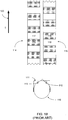
- FIGS. IA and IB are diagrammatic representations of a previous field sequential stereoscopic projection system.
- the system illustrated in FIGs. IA and IB has had a successful commercial embodiment under the trade name ZScreen.
- Video server 101 has cable 102 connecting to projector 103.
- Video synchronization information is transmitted from the projector 103 by means of cable 104 to control box 105.
- Control box 105 energizes, using cable 106, the ZScreen modulator 107.
- the ZScreen modulator has been described in great detail in Lipton U.S. Patent No. 4,792,850 .
- the ZScreen is an electro- optical modulator that switches between left- and right-handed circularly polarized light at video field rate.
- a polarization-conserving screen 109 When used in front of the projection lens 110 the result is that, when observer 108 is wearing analyzing eyewear, only the left eye sees a train of left images and not right images, and vice versa. It is highly preferable to use a polarization-conserving screen 109, and such screens are generally well known.
- FIG. 1B illustrates the separate trains of left and right images as projected field sequentially.
- the observer 110 wearing stereoscopic eyewear 111 observes images with left eye 113 and right eye 112.
- the fusion of the left- and right-eye images produces the stereoscopic image.
- a diagrammatic representation of the two trains of images is shown for the left train 114 and the right train 115.
- Field 116 is blank for the left image, as is 118 for the right image, and as depicted, these are out of phase.
- Typical left and right image fields, fields 117 and 119 respectively, are depicted out of phase.
- the time line given by T and the single-headed arrow 120 is shown to indicate the progression of fields.
- the left and right eyes of the observer see a train of left and right images emerging from a single projector.
- each eye is seeing nothing, because it is seeing a succession or train of fields that are made up of image fields followed by a blank field so that, in effect, half of the fields projected by the single projector 103 are used for one eye and half are used for the other eye in sequence as depicted.
- This sequence is called, by those in computer graphics "page-flipping," also known as the "time-multiplexed" or field-sequential approach.
- page-flipping also known as the "time-multiplexed" or field-sequential approach.
- the single projector approach is a more modem approach that has been used in the last 15 years or so and only lately in the commercial cinema. Originally this stereoscopic approach was introduced for industrial virtual reality or for corporate presentations, but has not, until lately, become a commercially viable product for the cinema.
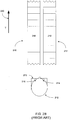
- FIGS. 2A and 2B the original method shown in FIGS. 2A and 2B has been in existence since the 1930s and uses two projectors. This method is used in location-based entertainment, in theme parks, and was used in the theatrical cinema in the 1950s.
- the major advantage of using a double projector is brightness. Compared to the field sequential system of FIGS. 1A and 1B , which employs a single projector, two projector arrangements are twice as bright.
- FIG. 2A show the previous dual projection setup comprising left and right projectors 206 and 207, with left and right servers 201 and 203 respectively.
- the servers 201 and 203 are synchronized by means of cable 202 so that the images transmitted from the left and right projectors 206 and 207 will be in synchrony and in phase.
- the left and right cables 204 and 205 respectively, feed projectors 206 and 207.
- In front of projector 206's lens 212 is a sheet polarizer 208, and in front of feed projector 207's lens 213 is sheet polarizer 209.
- a single server can output both left and right fields and this is also true for the field sequential approach described with the aid of FIGS. 1A and 1B .
- the essence of these teachings, specifically in the context of FIGs. 2A and 2B has little or nothing to do with server configurations.
- Two servers may be configured, or a single server can provide source information for these projectors. Two servers are shown in this arrangement.
- the images projected by 206 and 207 through sheet polarizers 208 and 209 are reflected off of screen 210 and viewed by observer 211.
- the screen like that shown in FIG. 1A as screen 109, preferably conserves polarization.
- the polarization filters can be of the circular or linear varieties.
- FIG. 2B diagrams what the user's eyes see.
- the assumption is that the projectors in FIG. 2A are electronic projectors, or digital projectors, using the DLP light engine devised by Texas Instruments now embodied in projectors by Barco, Christie, and NEC.
- the designs presented herein are not limited to use of the DLP light engine. Nevertheless, in order to adequately describe the instant design, aspects are presented based on employing the design using a DLP light engine-based projector.
- the DLP light engine unlike motion picture projection, is essentially continuously "on."
- Motion picture projection requires occlusion of the projection fields for two reasons. First, when the film is advanced in the projector, travel-ghosts result if the interrupting shutter does not occlude the light and what is at that instant a vertically traveling piece of film. Also, the effective field rate is doubled by using the Pross shutter to interrupt the projection frame once the motion picture frame is at rest, thereby increasing the flicker rate and thus satisfying the critical "fusion frequency" requirement, i.e. that a motion picture image must be displayed at a minimum number of times per second to eliminate the perception of flutter.
- the left and right eyes see images continuously.
- Observer 221 is wearing stereoscopic analyzing eyewear 213 and is observing the image through left eye 215 and right eye 214. Shown is a train of left images at 216 and right images at 217, and typical fields 218 and 219 (that is to say, left and right fields respectively) are shown.
- the arrow marked as T at 220 shows the time dimension.
- projectors 206 and 207 provide the train of images 216 for the left eye and the train of images 217 for the right eye; and if everything is coordinated properly and the photography is done properly, the observer will see good quality stereoscopic images.
- the left and right image presentation sequence be properly coordinated. All of the binocular symmetrical constraints described above apply. If the focal lengths of the left lens and the right lens do not match, then problems arise with the geometric constraint. If the images are misaligned in the vertical or the horizontal, additional geometric problems occur. If the arc lamps of the two projectors are not adjusted to have more or less the same illumination intensity, the image can be difficult to look at in the sense that the observer will experience fatigue.
- FIGS. 1A and 1B because the left and right images are coming out of a single projector there is no opportunity for illumination and geometric asymmetries. These binocular symmetries are guaranteed. Both images are treated identically.
- the only symmetrical concern with the single projection ZScreen approach has to do with the temporal asymmetry.
- the images in FIGs. 1A and 1B cannot possibly be projected simultaneously since they are coming out of a single projector with the field sequential approach. This symmetrical concern can be overcome if the repetition rate is high enough - for example, at 144 frames per second for material that was shot at 24 frames per second, the industry standard as has been explained above.
- the present design addresses the illumination and temporal binocular symmetrical constraints in order to provide a brighter, better looking stereoscopic image that requires, after initial setup, little or no calibration.
- a projected stereoscopic image should do no harm and cause no viewer discomfort.
- Many previously available projection solutions caused viewer fatigue and discomfort.
- a novel and improved design, overcoming the pitfalls of the past, is preferably simple to use. In the case of a theatrical motion picture projector, if the projector does not run essentially unassisted, then the projector is not a practical product. Previous systems had employed projectors that required constant monitoring and repeated tweaking.
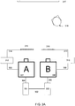
- FIG. 3A shows servers 301 and 303, used for the left and right images, respectively.
- a single server can be used to perform the functions of servers 301 and 303, or in other words a single server can provide images split between the left and right projectors.
- a single server may have two drives or the images can be formatted so that they can be encoded on a single drive.
- the servers 301 and 303 in the specific embodiment of FIG. 3A , are synchronized using cable 302, where synchronization comprises sending and receiving timing signals such that both projectors are projecting the required image at the appropriate time intervals.
- Cable 304 sends the video signal from server 301 to projector A, shown as projector 307.
- cable 305 sends the image from server 303 to projector B, shown as projector 306.
- Projector A sends a synchronization signal to control box 312 via cable 309.
- Projector B sends a synchronization signal to control box 310 via cable 308.
- Cable 314 sends power to push-pull modulator or ZScreen 315, and cable 313 sends power to push-pull or ZScreen modulator 316.
- the ZScreen modulator has been commercially available for about 20 years.
- Observer 318 views the image through polarized analyzing spectacles, as the image is reflected from polarization-conserving screen 317.
- Each projector receives both left and right image signals. Accordingly the signal fed to projector A via cable 305 has both left and right picture information and the signal fed to projector B has both left and right picture information.
- the third embodiment can be used in conjunction with the first two to enhance image resolution.
- the two projectors are run in synchrony.
- the ZScreen modulators 315 and 316 for the left and right modulators respectively are used to change the characteristic of polarized light at video field rate.
- Projector A projects a stream of left and right images
- projector B projects a different stream of left and right images.
- the projector on the left side projects both left and right images
- the projector on the right side projects both left and right images.
- the projectors in this mode of operation while in synchrony, have the projected fields phase adjusted so that unlike that which is represented in FIG. 1B , in which the eyes see images alternating with equal intervals of no image, in this case the eyes see image continuously.
- the images in this embodiment are in field-for-field synchronization, and such synchronization can be provided electronically, again by using timing signals between the devices to ensure the desired fields are being displayed at the desired times.
- a timing signal is sent between the two projectors and the same field is projected by each projector, each field being out of phase with the other.
- the degree of phase difference is variable between the two projectors, and depending on circumstances, different phase differences can produce better quality images.
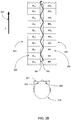
- FIG. 3B is used to explain this first embodiment.
- observer 319 is using circularly polarizing analyzing eyewear 320 in this case, to correspond with the output of the push-pull modulator or ZScreen.
- the left eye 322 sees only left images and the right eye 321 sees only the right images.
- the diagrammatic representation shows two trains of images, the left train 323 and the right train 324. Also shown is a typical frame 325 for the left image, and frame 326 for the right image.
- the vertical-going arrow marked with T at 327 is used to indicate the direction of time flow.
- Each projector shares the burden of producing both the left and right fields.
- a standing for the A projector of FIG. 3B and B standing for the B projector (A and B have been chosen so as not to confuse the left and right projectors in terms of their actual physical location with the left and right fields)
- R stands for the right perspective view.
- the subscripts identify the field number.
- the train is AL 1 , BL 1 , AL 1 , BL 1 , AL 2 ... and so on, for the left eye.
- the train is BR 1 , AR 1 , BR 1 , AR 1 , BR 2 ... and so on.
- projection occurs using two projectors, and progresses in a first eye from first (A) projector, left field 1, second (B) projector, left field 1, first (A) projector, left field 1, second (B) projector, left field 1, first (A) projector, left field 2, second (B) projector, left field 2, and so forth.
- fields progress from second (B) projector, right field 1, first (A) projector, right field 1, second (B) projector, right field 1, first (A) projector, right field 1, second (B) projector, right field 2, and so forth. While the left eye is seeing AL 1 , the right eye is at the same time seeing BR 1 , and so on.
- the representation of the two field trains is a sequential order of what the observer's eyes see.
- a or B projector projects in accordance with the progression represented by line 351, while the B projector projects in accordance with the sequence shown by line 352.
- Lines 351 and 352 therefore each represent a field train transmitted by a projector, 351 representing the field train for the A projector and 352 the field train for the B projector.
- the field trains 323 and 324 represent field trains perceived by the observer's left and right eye, respectively.
- projector A first transmits AL 1 while projector B at the same time (or substantially the same time) transmits BR 1 .
- projector A transmits AR 1
- projector B transmits BL 1 .
- No blank images or fields are transmitted, and the net effect is an increase in the overall brightness perceived and temporal and illumination asymmetries are eliminated or substantially reduced.
- the user's left eye perceives AL 1 , then BL 1 , then AL 1 , then BL 1 , then AL 2 , and so forth, while his right eye observes AR 1 , BR 1 , AR 1 , BR 1 , AR 2 , etc.
- the A projector is therefore used for both left and right images and the B projector is used in the same manner. Therefore, the left eye sees a train of images that have originated from both the A and the B projectors, and the right eye sees a train of images that have originated from the A and B projectors.
- the projectors are adjusted in this arrangement to be out of phase. By running the projectors and the ZScreens out of phase, the image appears to be "on" continuously.
- Illumination and temporal symmetries can benefit from the design illustrated in FIG. 3B .
- the left and right images are essentially mixed or combined (in sequence by means of the persistence of vision) so that each eye sees a rapid succession of left images which originate from both A and B projectors, and right images which originate from both A and B projectors.
- the two illumination sources in terms of all illumination asymmetries - intensity or brightness of the image, vignetting, and also color balance - are mixed. Since both projectors contribute each image or field, even if the two projectors are not in good symmetry in terms of illumination, because the signals are mixed, the end result is that both left and right images are balanced. Assuming that the projectors are properly set up, even if they do drift apart over time, despite the fact that this is a dual projector setup, the ensemble behaves like a single field sequential projector in which left and right fields are treated identically.
- the left and right trains of images are viewed continuously, so there is no blank period and the eyes are seeing images continuously. This can eliminate temporal asymmetry.
- the projectors may be run in the so-called “double-flash” mode in which each field or frame is concatenated and repeated twice, and the repetition rate is 96 frames per second, or they may be run in the so-called “triple-flash” mode in which each frame is concatenated and repeated three times for a total repetition rate of 144 frames per second.
- Single flash may be employed in certain circumstances. This arrangement can provide an extreme increase in brightness using the design of FIGs. 1A and 1B .
- the second embodiment runs both projectors in phase rather than the out of phase operation of the first embodiment.
- Running both projectors in phase provides field trains identical to those described with respect to FIG. 1B , but cures illumination asymmetry because the images have a simultaneously blended illumination. This result is due to the left train of images 114 and the right train of images 115, with respect to FIG. 1B , mixing. Since the images are in phase the alternating of images characteristic of single projector field sequential projection results, despite the fact that two projectors are employed. Temporal asymmetry cannot be cured because the projectors are in phase. Accordingly, for example, frame 117 of FIG. 1B is made up of both the A and B left images and frame 119 is made up both the A and B right images, so that the result is that these images are mixed and illumination symmetry is guaranteed.
- the net effect of this second embodiment is an increase in the overall brightness perceived and illumination asymmetries are eliminated or substantially reduced.
- the images are mixed by means of the psychophysical phenomenon of the persistence of vision.
- the image fields are simply mixed additively simultaneously, but the end result is perceptually the same, namely consistently uniform left and right trains of image fields.
- the progression of frames is, for the left eye, blank, left eye image 1, blank, left eye image 2, blank, left eye image 3, and so forth.
- progression is right eye image 1, blank, right eye image 2, blank, right eye image 3, blank, and so forth.
- progression for left eye is blank, left 1 plus right 1, blank, left 2 plus right 2, blank, left 3 plus right 3, blank, and so forth.
- progression for right eye is left 1 plus right 1, blank, left 2 plus right 2, blank, left 3 plus right 3, blank, and so forth.
- the third embodiment may be applied to both the first and second embodiments and is based on the television concept of interlace.
- interlace is a bandwidth reducing technique to improve resolution.
- This third embodiment is a variation on that concept but because the design differs in two significant respects it is termed "quasi-interlace.”
- TV interlace uses successive lines of a scanned image, alternating every other line, to build the image. If the images are repeated at a sufficient rate, no flicker results.
- interlace captures one field, or one half image, at a time. In quasi-interlace, the system captures the entire image at once and then deconstructs the image to meet the format requirements of digital projection.
- TV interlace alternates lines such that horizontal lines do not overlap.
- the lines overlap to the extent that half of each line is covered alternately by its simultaneously written or successively written line.
- quasi-interlace departs from television interlace is that when applied to the second embodiment, quasi-interlace comprises a simultaneous display of both interlace elopements. In the case of quasi-interlace, as applied to the first embodiment described above, the result more nearly resembles the traditional interlace technique.
- Quasi-interlace is described with the help of FIGs. 4A through 4C .
- An image that is twice the resolution of the projector's capability is used as a starting point. That is to say, the image frame has twice the number of pixels as that which the projector is capable of handling.
- the High Resolution Image is deconstructed and turned into two quasi-interlaced image fields, M and N.
- M contains half the number of pixels as the original image as does N.
- Half of the rows, or horizontal lines of pixels, are shifted to M and half to N.
- no space or empty image area exists between lines because the lines abut one another.
- FIG. 4B shows the final image quasi-interlaced as projected on the screen.
- the screen 401 includes image 402.
- Area 403 indicates an area to expand and evaluate, and the expanded area is shown in 404.
- Projectors A and B from FIG. 3A are adjusted to be displaced by one half a pixel in the vertical, horizontal, or diagonal direction so that the overlap pattern given in 404 is fulfilled.
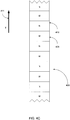
- FIG. 4C illustrates the train of fields for one eye. It is not necessary to describe the field train for two eyes since such an explanation is redundant because each eye, in the case of quasi-interlace, is handled as a separate entity and is not the subject of a stereoscopic combination. Quasi-interlace is typically employed with multiple projectors, in stereoscopic modes, but may also be employed in planar modes using multiple projectors.
- FIG. 4C presents field train 408 made up of quasi-interlaced fields M 409 and N 410. The combination of successive quasi-interlaced images by the eye-brain depends on the persistence of vision to achieve the effect of combining two half resolution images into one full or high resolution image.
- Quasi-interlace does not need to take the form of horizontal lines.
- the process can involve vertical lines, or diagonal offset, or an image that has been deconstructed along the lines of, for example, a checkerboard, or other arrangements.
- All of the embodiments provided above include what may be considered a safety mode. If one of the two projectors fails, the safety mode ensures that the display continues, as sufficient stereoscopic images will be transmitted to the screen to enable a user to view the movie and perceive the stereoscopic effect.
- the safety mode ensures that the display continues, as sufficient stereoscopic images will be transmitted to the screen to enable a user to view the movie and perceive the stereoscopic effect.
- the prior system such as the system of FIG. 1A and 1B
- a projector failure disrupts a critical component of the stereoscopic images and the stereoscopic effect cannot be perceived.
- the image is still projected with full stereoscopic depth but certain attributes will be lacking in the event of such a failure. For example, brightness will suffer or resolution will be reduced.
- such a failure is not catastrophic because the arrangement provides for continued operation even in the event that one of the two projectors fails to operate.
Landscapes
- Engineering & Computer Science (AREA)
- Multimedia (AREA)
- Signal Processing (AREA)
- Physics & Mathematics (AREA)
- General Physics & Mathematics (AREA)
- Testing, Inspecting, Measuring Of Stereoscopic Televisions And Televisions (AREA)
- Stereoscopic And Panoramic Photography (AREA)
- Projection Apparatus (AREA)
Claims (15)
- Procédé permettant de projeter des images stéréoscopiques en utilisant un dispositif de projecteurs multiples comprenant un premier projecteur (206) et un second projecteur (207), ce procédé comprenant des étapes consistant à :transmettre un premier train de champ à partir du premier projecteur (206), ce premier train de champ comprenant des premières images gauche et droite de projecteur, ettransmettre, simultanément, un second train de champ à partir du second projecteur (207), ce second train de champ comprenant des images droite et gauche de projecteur,la première image gauche de projecteur étant transmise par le premier projecteur essentiellement en même temps que la transmission de la seconde image droite de projecteur par le second projecteur, et le premier projecteur et le second projecteur étant chacun adapté pour projeter en alternance de la lumière ayant une première polarisation et de la lumière ayant une seconde polarisation en synchronisme avec les trains de champ vidéo.
- Procédé conforme à la revendication 1,
selon lequel le premier train de champ et le second train de champ sont exempts d'images vierges. - Procédé conforme à la revendication 1,
selon lequel en outre, la seconde image gauche de projecteur est transmise par le second projecteur après la première image gauche de projecteur et essentiellement en même temps que la transmission de la première image droite de projecteur par le premier projecteur. - Procédé conforme à la revendication 1,
comprenant en outre une étape consistant à subdiviser les images en des premières images gauche de projecteur des premières images droite de projecteur des secondes images gauche de projecteur et des secondes images droite de projecteur, cette subdivision s'effectuant avant la transmission. - Procédé conforme à la revendication 1,
selon lequel l'oeil gauche d'un observateur perçoit une première image gauche de projecteur transmise à partir du premier projecteur suivie par une seconde image gauche de projecteur transmise à partir du second projecteur. - Procédé conforme à l'une quelconque des revendications 1 à 5,
selon lequel les projecteurs sont actionnés selon un mode double flash dans lequel chaque champ est enchaîné en cascade et répété deux fois. - Procédé conforme à l'une quelconque des revendications 1 à 6,
selon lequel les projecteurs sont actionnés selon un mode triple flash dans lequel chaque trame est enchaînée en cascade et répétée trois fois. - Procédé conforme à la revendication 1,
comprenant en outre une étape consistant à quasi-entrelacer les images, ce quasi-entrelacement comprenant une étape consistant à déconstruire chacune des images en divisant des pixels dans chaque image pour former deux sous-images, chaque sous-image comprenant une série complémentaire de régions comprenant moins de pixels que dans chacune des images. - Procédé conforme à la revendication 8,
selon lequel lorsque la première image gauche de projecteur est transmise à partir du premier projecteur et que la seconde image gauche de projecteur est transmise à partir du second projecteur l'oeil droit d'un observateur ne perçoit pas une partie significative de cette image. - Appareil de projection réalisé pour permettre de projeter des images stéréoscopiques comprenant un premier projecteur conformé pour permettre de transmettre un premier train de champ, ce premier train de champ comprenant des premières images gauche et droite de projecteur, et un second projecteur conformé pour permettre de transmettre de façon simultanée un second train de champ, ce second train de champ comprenant des secondes images droite et gauche de projecteur, la première image gauche de projecteur étant transmise par le premier projecteur essentiellement simultanément à la transmission de la seconde image droite de projecteur par le second projecteur et le premier projecteur et le second projecteur étant adaptés chacun pour projeter en alternance de la lumière ayant une première polarisation et de la lumière ayant une seconde polarisation en synchronisme avec les trains de champ.
- Appareil de projection conforme à la revendication 10, comprenant en outre un élément de connexion entre le premier projecteur et le second projecteur, cet élément de connexion étant conformé pour permettre la transmission de signaux de synchronisation entre le premier projecteur et le second projecteur.
- Appareil de projection conforme à la revendication 10, satisfaisant à au moins l'une des conditions suivantes :A) le premier train de champ et le second train de champ sont exempts d'images vierges,B) chacune des premières images gauche de projecteur et chacune des premières images droite de projecteur se présente au moins une fois selon une succession alternée dans le premier train de champ.
- Appareil de projection conforme à la revendication 10, dans lequel l'oeil gauche d'un observateur perçoit une première image gauche de projecteur transmise à partir du premier projecteur suivie par une seconde image gauche de projecteur transmise à partir du second projecteur.
- Appareil de projection conforme à la revendication 10, comprenant en outre un ensemble de serveurs conçu pour permettre de diviser des images en des premières images gauche de projecteur, des premières images droite de projecteur, des secondes images gauche de projecteur et des secondes images droite de projecteur et pour transmettre les premières images gauche de projecteur et les premières images droite de projecteur au premier projecteur et les secondes images gauche de projecteur et les secondes images droite de projecteur au second projecteur.
- Appareil de projection conforme à la revendication 14,
dans lequel l'ensemble de serveurs est en outre conçu pour quasi entrelacer les images, ce quasi entrelacement comprenant une déconstruction de chaque image par division de pixels dans chaque image en deux sous-images, chaque sous-image comprenant une série complémentaire de régions comprenant moins de pixels que dans chacune des images.
Applications Claiming Priority (2)
| Application Number | Priority Date | Filing Date | Title |
|---|---|---|---|
| US11/583,245 US7670004B2 (en) | 2006-10-18 | 2006-10-18 | Dual ZScreen® projection |
| PCT/US2007/021781 WO2008048480A2 (fr) | 2006-10-18 | 2007-10-11 | Projection avec un écran zscreen ® double |
Publications (3)
| Publication Number | Publication Date |
|---|---|
| EP2074831A2 EP2074831A2 (fr) | 2009-07-01 |
| EP2074831A4 EP2074831A4 (fr) | 2012-02-22 |
| EP2074831B1 true EP2074831B1 (fr) | 2017-03-15 |
Family
ID=39314599
Family Applications (1)
| Application Number | Title | Priority Date | Filing Date |
|---|---|---|---|
| EP07839482.2A Active EP2074831B1 (fr) | 2006-10-18 | 2007-10-11 | Projection avec un écran zscreen ® double |
Country Status (5)
| Country | Link |
|---|---|
| US (2) | US7670004B2 (fr) |
| EP (1) | EP2074831B1 (fr) |
| JP (1) | JP2010507332A (fr) |
| KR (1) | KR20090079959A (fr) |
| WO (1) | WO2008048480A2 (fr) |
Families Citing this family (68)
| Publication number | Priority date | Publication date | Assignee | Title |
|---|---|---|---|---|
| GB0522968D0 (en) | 2005-11-11 | 2005-12-21 | Popovich Milan M | Holographic illumination device |
| GB0718706D0 (en) | 2007-09-25 | 2007-11-07 | Creative Physics Ltd | Method and apparatus for reducing laser speckle |
| EP2851735A1 (fr) | 2006-09-29 | 2015-03-25 | Real Inc. | Systèmes de conversion de polarisation pour projection stéréoscopique |
| JP5641424B2 (ja) | 2007-05-09 | 2014-12-17 | リアルディー インコーポレイテッドRealD Inc. | 立体視投影用の偏光変換システムおよび方法 |
| US7908233B2 (en) * | 2007-06-29 | 2011-03-15 | International Business Machines Corporation | Method and apparatus for implementing digital video modeling to generate an expected behavior model |
| US7675513B2 (en) * | 2008-03-14 | 2010-03-09 | Evans & Sutherland Computer Corp. | System and method for displaying stereo images |
| US8411137B2 (en) * | 2008-07-16 | 2013-04-02 | Dolby Laboratories Licensing Corporation | Dual projection system with inversely synchronized channel projections |
| USD666663S1 (en) | 2008-10-20 | 2012-09-04 | X6D Limited | 3D glasses |
| USRE45394E1 (en) | 2008-10-20 | 2015-03-03 | X6D Limited | 3D glasses |
| USD624952S1 (en) | 2008-10-20 | 2010-10-05 | X6D Ltd. | 3D glasses |
| USD603445S1 (en) | 2009-03-13 | 2009-11-03 | X6D Limited | 3D glasses |
| CA2684513A1 (fr) | 2008-11-17 | 2010-05-17 | X6D Limited | Lunettes de vision tridimensionnelle ameliorees |
| US8542326B2 (en) | 2008-11-17 | 2013-09-24 | X6D Limited | 3D shutter glasses for use with LCD displays |
| USD646451S1 (en) | 2009-03-30 | 2011-10-04 | X6D Limited | Cart for 3D glasses |
| US9335604B2 (en) | 2013-12-11 | 2016-05-10 | Milan Momcilo Popovich | Holographic waveguide display |
| US11726332B2 (en) | 2009-04-27 | 2023-08-15 | Digilens Inc. | Diffractive projection apparatus |
| USD672804S1 (en) | 2009-05-13 | 2012-12-18 | X6D Limited | 3D glasses |
| USD650956S1 (en) | 2009-05-13 | 2011-12-20 | X6D Limited | Cart for 3D glasses |
| US20100321382A1 (en) | 2009-06-18 | 2010-12-23 | Scalable Display Technologies, Inc. | System and method for injection of mapping functions |
| US9341846B2 (en) | 2012-04-25 | 2016-05-17 | Rockwell Collins Inc. | Holographic wide angle display |
| US11204540B2 (en) | 2009-10-09 | 2021-12-21 | Digilens Inc. | Diffractive waveguide providing a retinal image |
| USD671590S1 (en) | 2010-09-10 | 2012-11-27 | X6D Limited | 3D glasses |
| USD669522S1 (en) | 2010-08-27 | 2012-10-23 | X6D Limited | 3D glasses |
| USD692941S1 (en) | 2009-11-16 | 2013-11-05 | X6D Limited | 3D glasses |
| EP2526461B1 (fr) | 2010-01-20 | 2023-06-07 | RealD Inc. | Système de projection stéréoscopique à champ de vision large |
| USD662965S1 (en) | 2010-02-04 | 2012-07-03 | X6D Limited | 3D glasses |
| KR20110096494A (ko) | 2010-02-22 | 2011-08-30 | 엘지전자 주식회사 | 전자 장치 및 입체영상 재생 방법 |
| JP2011248323A (ja) * | 2010-04-30 | 2011-12-08 | Canon Inc | 画像処理装置及びその制御方法 |
| USD664183S1 (en) | 2010-08-27 | 2012-07-24 | X6D Limited | 3D glasses |
| US9274349B2 (en) | 2011-04-07 | 2016-03-01 | Digilens Inc. | Laser despeckler based on angular diversity |
| EP2719185B1 (fr) * | 2011-06-13 | 2020-12-23 | Dolby Laboratories Licensing Corporation | Système de projection |
| WO2013027004A1 (fr) | 2011-08-24 | 2013-02-28 | Milan Momcilo Popovich | Affichage de données vestimentaire |
| WO2016020630A2 (fr) | 2014-08-08 | 2016-02-11 | Milan Momcilo Popovich | Illuminateur laser en guide d'ondes comprenant un dispositif de déchatoiement |
| US10670876B2 (en) | 2011-08-24 | 2020-06-02 | Digilens Inc. | Waveguide laser illuminator incorporating a despeckler |
| US20150010265A1 (en) | 2012-01-06 | 2015-01-08 | Milan, Momcilo POPOVICH | Contact image sensor using switchable bragg gratings |
| US9456744B2 (en) | 2012-05-11 | 2016-10-04 | Digilens, Inc. | Apparatus for eye tracking |
| USD711959S1 (en) | 2012-08-10 | 2014-08-26 | X6D Limited | Glasses for amblyopia treatment |
| US9933684B2 (en) * | 2012-11-16 | 2018-04-03 | Rockwell Collins, Inc. | Transparent waveguide display providing upper and lower fields of view having a specific light output aperture configuration |
| US10209517B2 (en) | 2013-05-20 | 2019-02-19 | Digilens, Inc. | Holographic waveguide eye tracker |
| WO2015015138A1 (fr) | 2013-07-31 | 2015-02-05 | Milan Momcilo Popovich | Méthode et appareil de détection d'une image par contact |
| WO2015073838A1 (fr) | 2013-11-15 | 2015-05-21 | Reald Inc. | Systèmes de projection à plage dynamique étendue et à contraste élevé |
| WO2016020632A1 (fr) | 2014-08-08 | 2016-02-11 | Milan Momcilo Popovich | Procédé pour gravure par pressage et réplication holographique |
| WO2016042283A1 (fr) | 2014-09-19 | 2016-03-24 | Milan Momcilo Popovich | Procédé et appareil de production d'images d'entrée pour affichages à guides d'ondes holographiques |
| WO2016046514A1 (fr) | 2014-09-26 | 2016-03-31 | LOKOVIC, Kimberly, Sun | Dispositif de poursuite optique à guide d'ondes holographique |
| EP3245551B1 (fr) | 2015-01-12 | 2019-09-18 | DigiLens Inc. | Afficheurs à champ lumineux et à guide d'ondes |
| US10437064B2 (en) | 2015-01-12 | 2019-10-08 | Digilens Inc. | Environmentally isolated waveguide display |
| US10330777B2 (en) | 2015-01-20 | 2019-06-25 | Digilens Inc. | Holographic waveguide lidar |
| US9632226B2 (en) | 2015-02-12 | 2017-04-25 | Digilens Inc. | Waveguide grating device |
| US10459145B2 (en) | 2015-03-16 | 2019-10-29 | Digilens Inc. | Waveguide device incorporating a light pipe |
| US10591756B2 (en) | 2015-03-31 | 2020-03-17 | Digilens Inc. | Method and apparatus for contact image sensing |
| CN113759555B (zh) | 2015-10-05 | 2024-09-20 | 迪吉伦斯公司 | 波导显示器 |
| WO2017134412A1 (fr) | 2016-02-04 | 2017-08-10 | Milan Momcilo Popovich | Dispositif de poursuite optique de guide d'onde holographique |
| JP6895451B2 (ja) | 2016-03-24 | 2021-06-30 | ディジレンズ インコーポレイテッド | 偏光選択ホログラフィー導波管デバイスを提供するための方法および装置 |
| JP6734933B2 (ja) | 2016-04-11 | 2020-08-05 | ディジレンズ インコーポレイテッド | 構造化光投影のためのホログラフィック導波管装置 |
| US11513350B2 (en) | 2016-12-02 | 2022-11-29 | Digilens Inc. | Waveguide device with uniform output illumination |
| US10545346B2 (en) | 2017-01-05 | 2020-01-28 | Digilens Inc. | Wearable heads up displays |
| US10942430B2 (en) | 2017-10-16 | 2021-03-09 | Digilens Inc. | Systems and methods for multiplying the image resolution of a pixelated display |
| GB2605118A (en) * | 2017-11-16 | 2022-09-21 | Interesting Av Ltd | Apparatus and method |
| CN116224492A (zh) | 2018-01-08 | 2023-06-06 | 迪吉伦斯公司 | 用于制造波导单元的系统和方法 |
| WO2019136476A1 (fr) | 2018-01-08 | 2019-07-11 | Digilens, Inc. | Architectures de guides d'ondes et procédés de fabrication associés |
| US10732569B2 (en) | 2018-01-08 | 2020-08-04 | Digilens Inc. | Systems and methods for high-throughput recording of holographic gratings in waveguide cells |
| CN112088332A (zh) | 2018-03-16 | 2020-12-15 | 迪吉伦斯公司 | 包含双折射控制的全息波导及用于它们的制造的方法 |
| WO2020023779A1 (fr) | 2018-07-25 | 2020-01-30 | Digilens Inc. | Systèmes et procédés pour fabriquer une structure optique multicouches |
| EP3924759A4 (fr) | 2019-02-15 | 2022-12-28 | Digilens Inc. | Procédés et appareils pour fournir un affichage de guide d'ondes holographique à l'aide de réseaux intégrés |
| WO2020186113A1 (fr) | 2019-03-12 | 2020-09-17 | Digilens Inc. | Rétroéclairage de guide d'ondes holographique et procédés de fabrication associés |
| KR20220016990A (ko) | 2019-06-07 | 2022-02-10 | 디지렌즈 인코포레이티드. | 투과 및 반사 격자를 통합하는 도파관 및 관련 제조 방법 |
| JP2022543571A (ja) | 2019-07-29 | 2022-10-13 | ディジレンズ インコーポレイテッド | 画素化されたディスプレイの画像解像度および視野を乗算するための方法および装置 |
| JP2022546413A (ja) | 2019-08-29 | 2022-11-04 | ディジレンズ インコーポレイテッド | 真空回折格子および製造方法 |
Family Cites Families (30)
| Publication number | Priority date | Publication date | Assignee | Title |
|---|---|---|---|---|
| US2729138A (en) * | 1951-07-17 | 1956-01-03 | Synthetic Vision Corp | System and apparatus for projecting three dimensional motion pictures |
| KR930009882B1 (ko) * | 1987-10-31 | 1993-10-12 | 주식회사 금성사 | 고휘도 입체용 엘씨디 프로젝터 구동장치 |
| US4792850A (en) * | 1987-11-25 | 1988-12-20 | Sterographics Corporation | Method and system employing a push-pull liquid crystal modulator |
| US5239372A (en) * | 1991-12-31 | 1993-08-24 | Stereographics Corporation | Stereoscopic video projection system |
| GB2267579A (en) * | 1992-05-15 | 1993-12-08 | Sharp Kk | Optical device comprising facing lenticular or parallax screens of different pitch |
| JP3323575B2 (ja) * | 1993-03-16 | 2002-09-09 | 日本放送協会 | 眼鏡なし3次元画像表示装置 |
| JPH0728178A (ja) * | 1993-07-13 | 1995-01-31 | Sanyo Electric Co Ltd | 投写型3次元画像表示装置 |
| JPH07134275A (ja) * | 1993-11-08 | 1995-05-23 | Mitsubishi Electric Corp | 投写型表示装置 |
| JPH07140933A (ja) * | 1993-11-16 | 1995-06-02 | Sanyo Electric Co Ltd | 液晶表示装置の駆動方法 |
| US6608652B1 (en) * | 1995-10-14 | 2003-08-19 | Semiconductor Energy Laboratory Co., Ltd. | Image display system and method |
| GB2309847B (en) * | 1995-10-19 | 1999-09-15 | Sony Corp | Stereoscopic image generation method and apparatus thereof |
| JP2846856B2 (ja) * | 1996-07-19 | 1999-01-13 | 三洋電機株式会社 | 立体映像表示装置 |
| JP3500083B2 (ja) * | 1999-01-11 | 2004-02-23 | 三洋電機株式会社 | 眼鏡無し立体映像表示装置 |
| US20010028416A1 (en) * | 2000-02-03 | 2001-10-11 | Divelbiss Adam W. | System and method for displaying 3D imagery using a dual projector 3D stereoscopic projection system |
| CA2403483A1 (fr) * | 2000-03-15 | 2001-09-20 | Steven Charles Read | Procedes et appareils de superposition d'images |
| US20030020809A1 (en) | 2000-03-15 | 2003-01-30 | Gibbon Michael A | Methods and apparatuses for superimposition of images |
| JP3990141B2 (ja) * | 2001-11-08 | 2007-10-10 | Nec液晶テクノロジー株式会社 | 液晶表示装置 |
| JP2003185969A (ja) * | 2001-12-17 | 2003-07-03 | Sanyo Electric Co Ltd | 立体視液晶プロジェクタシステム |
| JP3891000B2 (ja) * | 2002-02-15 | 2007-03-07 | 日本ビクター株式会社 | 液晶表示装置およびその駆動方法 |
| EP1450568A3 (fr) * | 2003-02-21 | 2009-08-26 | Barco N.V. | Méthode de transmission de signaux dans un système de projection et système de projection qui applique la méthode |
| US7411611B2 (en) * | 2003-08-25 | 2008-08-12 | Barco N. V. | Device and method for performing multiple view imaging by means of a plurality of video processing devices |
| ATE418236T1 (de) * | 2003-10-21 | 2009-01-15 | Barco Nv | Verfahren und vorrichtung zur durchführung einer stereoskopischen bildanzeige auf der basis von farbselektiven filtern |
| US7227568B2 (en) * | 2004-04-03 | 2007-06-05 | Li Sun | Dual polarizing light filter for 2-D and 3-D display |
| JP4349963B2 (ja) * | 2004-04-05 | 2009-10-21 | 株式会社有沢製作所 | 立体画像表示装置 |
| KR100616556B1 (ko) * | 2004-06-12 | 2006-08-28 | 김은수 | 무손실 편광형 입체 디스플레이방법 및 장치 |
| US7236175B2 (en) * | 2004-08-13 | 2007-06-26 | National Center For High Performance Computing | Apparatus for projecting computer generated stereoscopic images |
| JP2006133741A (ja) * | 2004-10-06 | 2006-05-25 | Canon Inc | 画像表示装置、映像受信表示装置 |
| US7387392B2 (en) * | 2005-09-06 | 2008-06-17 | Simon Widdowson | System and method for projecting sub-frames onto a surface |
| US7477206B2 (en) * | 2005-12-06 | 2009-01-13 | Real D | Enhanced ZScreen modulator techniques |
| US7857455B2 (en) * | 2006-10-18 | 2010-12-28 | Reald Inc. | Combining P and S rays for bright stereoscopic projection |
-
2006
- 2006-10-18 US US11/583,245 patent/US7670004B2/en active Active
-
2007
- 2007-10-11 EP EP07839482.2A patent/EP2074831B1/fr active Active
- 2007-10-11 JP JP2009533318A patent/JP2010507332A/ja active Pending
- 2007-10-11 WO PCT/US2007/021781 patent/WO2008048480A2/fr active Application Filing
- 2007-10-11 KR KR1020097010136A patent/KR20090079959A/ko not_active Application Discontinuation
-
2010
- 2010-02-25 US US12/713,051 patent/US20100214396A1/en not_active Abandoned
Non-Patent Citations (1)
| Title |
|---|
| None * |
Also Published As
| Publication number | Publication date |
|---|---|
| US20080143964A1 (en) | 2008-06-19 |
| KR20090079959A (ko) | 2009-07-22 |
| WO2008048480A2 (fr) | 2008-04-24 |
| US7670004B2 (en) | 2010-03-02 |
| JP2010507332A (ja) | 2010-03-04 |
| WO2008048480A3 (fr) | 2008-08-07 |
| EP2074831A2 (fr) | 2009-07-01 |
| EP2074831A4 (fr) | 2012-02-22 |
| US20100214396A1 (en) | 2010-08-26 |
Similar Documents
| Publication | Publication Date | Title |
|---|---|---|
| EP2074831B1 (fr) | Projection avec un écran zscreen ® double | |
| US7411611B2 (en) | Device and method for performing multiple view imaging by means of a plurality of video processing devices | |
| US8456516B2 (en) | Methods and systems for stereoscopic imaging | |
| US20100238274A1 (en) | Method of displaying three-dimensional image data and an apparatus of processing three-dimensional image data | |
| JP4827783B2 (ja) | 画像表示装置 | |
| Ezra et al. | New autostereoscopic display system | |
| US20080036854A1 (en) | Method and system of communicating and rendering stereoscopic and dual-view images | |
| TWI502958B (zh) | 立體影像顯示裝置及其方法 | |
| US9261710B2 (en) | 2D quality enhancer in polarized 3D systems for 2D-3D co-existence | |
| EP2387245A2 (fr) | Appareil d'affichage d'images tridimensionnel 3D et son procédé de commande | |
| US20100302235A1 (en) | efficient composition of a stereoscopic image for a 3-D TV | |
| KR20110025977A (ko) | 삼차원 프리젠테이션 동안의 이차원 컨텐트의 디스플레이 | |
| JPH08205201A (ja) | 疑似立体視方法 | |
| EP2595395A1 (fr) | Appareil dýaffichage et son procédé de commande | |
| EP1993294B1 (fr) | Système d'affichage stéréoscopique | |
| JP4932036B2 (ja) | 非整数フラッシュレートを有する3d投影システム | |
| US20130222374A1 (en) | Method for outputting three-dimensional (3d) image and display apparatus thereof | |
| Lipton et al. | A flicker-free field-sequential stereoscopic video system | |
| US20130044102A1 (en) | Method for outputting three-dimensional (3d) image and display apparatus thereof | |
| JP4969684B2 (ja) | 画像表示装置 | |
| KR20030046748A (ko) | 시분할 입체영상시스템 | |
| Lipton et al. | Eclipse projection | |
| JPH04107086A (ja) | 立体テレビ | |
| EP2341711A2 (fr) | Système d'affichage tridimensionnel (3D) | |
| JP2012165218A (ja) | 映像出力装置 |
Legal Events
| Date | Code | Title | Description |
|---|---|---|---|
| PUAI | Public reference made under article 153(3) epc to a published international application that has entered the european phase |
Free format text: ORIGINAL CODE: 0009012 |
|
| 17P | Request for examination filed |
Effective date: 20090420 |
|
| AK | Designated contracting states |
Kind code of ref document: A2 Designated state(s): AT BE BG CH CY CZ DE DK EE ES FI FR GB GR HU IE IS IT LI LT LU LV MC MT NL PL PT RO SE SI SK TR |
|
| DAX | Request for extension of the european patent (deleted) | ||
| RAP1 | Party data changed (applicant data changed or rights of an application transferred) |
Owner name: REALD INC. |
|
| A4 | Supplementary search report drawn up and despatched |
Effective date: 20120123 |
|
| RIC1 | Information provided on ipc code assigned before grant |
Ipc: H04N 13/04 20060101ALI20120117BHEP Ipc: H04N 13/00 20060101AFI20120117BHEP |
|
| 17Q | First examination report despatched |
Effective date: 20130213 |
|
| GRAP | Despatch of communication of intention to grant a patent |
Free format text: ORIGINAL CODE: EPIDOSNIGR1 |
|
| INTG | Intention to grant announced |
Effective date: 20161010 |
|
| RIN1 | Information on inventor provided before grant (corrected) |
Inventor name: COWAN, MATT Inventor name: GREER, JOSH Inventor name: LIPTON, LENNY |
|
| GRAS | Grant fee paid |
Free format text: ORIGINAL CODE: EPIDOSNIGR3 |
|
| GRAA | (expected) grant |
Free format text: ORIGINAL CODE: 0009210 |
|
| AK | Designated contracting states |
Kind code of ref document: B1 Designated state(s): AT BE BG CH CY CZ DE DK EE ES FI FR GB GR HU IE IS IT LI LT LU LV MC MT NL PL PT RO SE SI SK TR |
|
| REG | Reference to a national code |
Ref country code: CH Ref legal event code: EP Ref country code: GB Ref legal event code: FG4D |
|
| REG | Reference to a national code |
Ref country code: IE Ref legal event code: FG4D |
|
| REG | Reference to a national code |
Ref country code: AT Ref legal event code: REF Ref document number: 876649 Country of ref document: AT Kind code of ref document: T Effective date: 20170415 |
|
| REG | Reference to a national code |
Ref country code: DE Ref legal event code: R096 Ref document number: 602007050222 Country of ref document: DE |
|
| REG | Reference to a national code |
Ref country code: NL Ref legal event code: MP Effective date: 20170315 |
|
| REG | Reference to a national code |
Ref country code: LT Ref legal event code: MG4D |
|
| PG25 | Lapsed in a contracting state [announced via postgrant information from national office to epo] |
Ref country code: FI Free format text: LAPSE BECAUSE OF FAILURE TO SUBMIT A TRANSLATION OF THE DESCRIPTION OR TO PAY THE FEE WITHIN THE PRESCRIBED TIME-LIMIT Effective date: 20170315 Ref country code: LT Free format text: LAPSE BECAUSE OF FAILURE TO SUBMIT A TRANSLATION OF THE DESCRIPTION OR TO PAY THE FEE WITHIN THE PRESCRIBED TIME-LIMIT Effective date: 20170315 |
|
| REG | Reference to a national code |
Ref country code: AT Ref legal event code: MK05 Ref document number: 876649 Country of ref document: AT Kind code of ref document: T Effective date: 20170315 |
|
| PG25 | Lapsed in a contracting state [announced via postgrant information from national office to epo] |
Ref country code: BG Free format text: LAPSE BECAUSE OF FAILURE TO SUBMIT A TRANSLATION OF THE DESCRIPTION OR TO PAY THE FEE WITHIN THE PRESCRIBED TIME-LIMIT Effective date: 20170615 Ref country code: SE Free format text: LAPSE BECAUSE OF FAILURE TO SUBMIT A TRANSLATION OF THE DESCRIPTION OR TO PAY THE FEE WITHIN THE PRESCRIBED TIME-LIMIT Effective date: 20170315 Ref country code: LV Free format text: LAPSE BECAUSE OF FAILURE TO SUBMIT A TRANSLATION OF THE DESCRIPTION OR TO PAY THE FEE WITHIN THE PRESCRIBED TIME-LIMIT Effective date: 20170315 |
|
| PG25 | Lapsed in a contracting state [announced via postgrant information from national office to epo] |
Ref country code: NL Free format text: LAPSE BECAUSE OF FAILURE TO SUBMIT A TRANSLATION OF THE DESCRIPTION OR TO PAY THE FEE WITHIN THE PRESCRIBED TIME-LIMIT Effective date: 20170315 |
|
| PG25 | Lapsed in a contracting state [announced via postgrant information from national office to epo] |
Ref country code: EE Free format text: LAPSE BECAUSE OF FAILURE TO SUBMIT A TRANSLATION OF THE DESCRIPTION OR TO PAY THE FEE WITHIN THE PRESCRIBED TIME-LIMIT Effective date: 20170315 Ref country code: CZ Free format text: LAPSE BECAUSE OF FAILURE TO SUBMIT A TRANSLATION OF THE DESCRIPTION OR TO PAY THE FEE WITHIN THE PRESCRIBED TIME-LIMIT Effective date: 20170315 Ref country code: IT Free format text: LAPSE BECAUSE OF FAILURE TO SUBMIT A TRANSLATION OF THE DESCRIPTION OR TO PAY THE FEE WITHIN THE PRESCRIBED TIME-LIMIT Effective date: 20170315 Ref country code: AT Free format text: LAPSE BECAUSE OF FAILURE TO SUBMIT A TRANSLATION OF THE DESCRIPTION OR TO PAY THE FEE WITHIN THE PRESCRIBED TIME-LIMIT Effective date: 20170315 Ref country code: SK Free format text: LAPSE BECAUSE OF FAILURE TO SUBMIT A TRANSLATION OF THE DESCRIPTION OR TO PAY THE FEE WITHIN THE PRESCRIBED TIME-LIMIT Effective date: 20170315 Ref country code: ES Free format text: LAPSE BECAUSE OF FAILURE TO SUBMIT A TRANSLATION OF THE DESCRIPTION OR TO PAY THE FEE WITHIN THE PRESCRIBED TIME-LIMIT Effective date: 20170315 Ref country code: RO Free format text: LAPSE BECAUSE OF FAILURE TO SUBMIT A TRANSLATION OF THE DESCRIPTION OR TO PAY THE FEE WITHIN THE PRESCRIBED TIME-LIMIT Effective date: 20170315 |
|
| PG25 | Lapsed in a contracting state [announced via postgrant information from national office to epo] |
Ref country code: IS Free format text: LAPSE BECAUSE OF FAILURE TO SUBMIT A TRANSLATION OF THE DESCRIPTION OR TO PAY THE FEE WITHIN THE PRESCRIBED TIME-LIMIT Effective date: 20170715 Ref country code: PT Free format text: LAPSE BECAUSE OF FAILURE TO SUBMIT A TRANSLATION OF THE DESCRIPTION OR TO PAY THE FEE WITHIN THE PRESCRIBED TIME-LIMIT Effective date: 20170717 Ref country code: PL Free format text: LAPSE BECAUSE OF FAILURE TO SUBMIT A TRANSLATION OF THE DESCRIPTION OR TO PAY THE FEE WITHIN THE PRESCRIBED TIME-LIMIT Effective date: 20170315 |
|
| REG | Reference to a national code |
Ref country code: DE Ref legal event code: R097 Ref document number: 602007050222 Country of ref document: DE |
|
| PLBE | No opposition filed within time limit |
Free format text: ORIGINAL CODE: 0009261 |
|
| STAA | Information on the status of an ep patent application or granted ep patent |
Free format text: STATUS: NO OPPOSITION FILED WITHIN TIME LIMIT |
|
| PG25 | Lapsed in a contracting state [announced via postgrant information from national office to epo] |
Ref country code: DK Free format text: LAPSE BECAUSE OF FAILURE TO SUBMIT A TRANSLATION OF THE DESCRIPTION OR TO PAY THE FEE WITHIN THE PRESCRIBED TIME-LIMIT Effective date: 20170315 |
|
| 26N | No opposition filed |
Effective date: 20171218 |
|
| PG25 | Lapsed in a contracting state [announced via postgrant information from national office to epo] |
Ref country code: SI Free format text: LAPSE BECAUSE OF FAILURE TO SUBMIT A TRANSLATION OF THE DESCRIPTION OR TO PAY THE FEE WITHIN THE PRESCRIBED TIME-LIMIT Effective date: 20170315 |
|
| PG25 | Lapsed in a contracting state [announced via postgrant information from national office to epo] |
Ref country code: MC Free format text: LAPSE BECAUSE OF FAILURE TO SUBMIT A TRANSLATION OF THE DESCRIPTION OR TO PAY THE FEE WITHIN THE PRESCRIBED TIME-LIMIT Effective date: 20170315 |
|
| REG | Reference to a national code |
Ref country code: CH Ref legal event code: PL |
|
| REG | Reference to a national code |
Ref country code: IE Ref legal event code: MM4A |
|
| REG | Reference to a national code |
Ref country code: FR Ref legal event code: ST Effective date: 20180629 |
|
| PG25 | Lapsed in a contracting state [announced via postgrant information from national office to epo] |
Ref country code: LU Free format text: LAPSE BECAUSE OF NON-PAYMENT OF DUE FEES Effective date: 20171011 Ref country code: CH Free format text: LAPSE BECAUSE OF NON-PAYMENT OF DUE FEES Effective date: 20171031 Ref country code: LI Free format text: LAPSE BECAUSE OF NON-PAYMENT OF DUE FEES Effective date: 20171031 |
|
| REG | Reference to a national code |
Ref country code: BE Ref legal event code: MM Effective date: 20171031 |
|
| PG25 | Lapsed in a contracting state [announced via postgrant information from national office to epo] |
Ref country code: BE Free format text: LAPSE BECAUSE OF NON-PAYMENT OF DUE FEES Effective date: 20171031 Ref country code: FR Free format text: LAPSE BECAUSE OF NON-PAYMENT OF DUE FEES Effective date: 20171031 |
|
| PG25 | Lapsed in a contracting state [announced via postgrant information from national office to epo] |
Ref country code: MT Free format text: LAPSE BECAUSE OF NON-PAYMENT OF DUE FEES Effective date: 20171011 |
|
| PG25 | Lapsed in a contracting state [announced via postgrant information from national office to epo] |
Ref country code: IE Free format text: LAPSE BECAUSE OF NON-PAYMENT OF DUE FEES Effective date: 20171011 |
|
| PG25 | Lapsed in a contracting state [announced via postgrant information from national office to epo] |
Ref country code: HU Free format text: LAPSE BECAUSE OF FAILURE TO SUBMIT A TRANSLATION OF THE DESCRIPTION OR TO PAY THE FEE WITHIN THE PRESCRIBED TIME-LIMIT; INVALID AB INITIO Effective date: 20071011 |
|
| PG25 | Lapsed in a contracting state [announced via postgrant information from national office to epo] |
Ref country code: CY Free format text: LAPSE BECAUSE OF NON-PAYMENT OF DUE FEES Effective date: 20170315 |
|
| PG25 | Lapsed in a contracting state [announced via postgrant information from national office to epo] |
Ref country code: TR Free format text: LAPSE BECAUSE OF FAILURE TO SUBMIT A TRANSLATION OF THE DESCRIPTION OR TO PAY THE FEE WITHIN THE PRESCRIBED TIME-LIMIT Effective date: 20170315 |
|
| PG25 | Lapsed in a contracting state [announced via postgrant information from national office to epo] |
Ref country code: GR Free format text: LAPSE BECAUSE OF FAILURE TO SUBMIT A TRANSLATION OF THE DESCRIPTION OR TO PAY THE FEE WITHIN THE PRESCRIBED TIME-LIMIT Effective date: 20170315 |
|
| PGFP | Annual fee paid to national office [announced via postgrant information from national office to epo] |
Ref country code: GB Payment date: 20230920 Year of fee payment: 17 |
|
| PGFP | Annual fee paid to national office [announced via postgrant information from national office to epo] |
Ref country code: DE Payment date: 20230920 Year of fee payment: 17 |