EP2074369B1 - Impinging air ovens having high mass flow orifices - Google Patents
Impinging air ovens having high mass flow orifices Download PDFInfo
- Publication number
- EP2074369B1 EP2074369B1 EP07839497.0A EP07839497A EP2074369B1 EP 2074369 B1 EP2074369 B1 EP 2074369B1 EP 07839497 A EP07839497 A EP 07839497A EP 2074369 B1 EP2074369 B1 EP 2074369B1
- Authority
- EP
- European Patent Office
- Prior art keywords
- orifices
- air
- oven
- columnating
- plate
- Prior art date
- Legal status (The legal status is an assumption and is not a legal conclusion. Google has not performed a legal analysis and makes no representation as to the accuracy of the status listed.)
- Not-in-force
Links
Images


Classifications
-
- F—MECHANICAL ENGINEERING; LIGHTING; HEATING; WEAPONS; BLASTING
- F27—FURNACES; KILNS; OVENS; RETORTS
- F27B—FURNACES, KILNS, OVENS, OR RETORTS IN GENERAL; OPEN SINTERING OR LIKE APPARATUS
- F27B9/00—Furnaces through which the charge is moved mechanically, e.g. of tunnel type; Similar furnaces in which the charge moves by gravity
- F27B9/06—Furnaces through which the charge is moved mechanically, e.g. of tunnel type; Similar furnaces in which the charge moves by gravity heated without contact between combustion gases and charge; electrically heated
- F27B9/10—Furnaces through which the charge is moved mechanically, e.g. of tunnel type; Similar furnaces in which the charge moves by gravity heated without contact between combustion gases and charge; electrically heated heated by hot air or gas
-
- A—HUMAN NECESSITIES
- A21—BAKING; EDIBLE DOUGHS
- A21B—BAKERS' OVENS; MACHINES OR EQUIPMENT FOR BAKING
- A21B1/00—Bakers' ovens
- A21B1/02—Bakers' ovens characterised by the heating arrangements
- A21B1/24—Ovens heated by media flowing therethrough
- A21B1/245—Ovens heated by media flowing therethrough with a plurality of air nozzles to obtain an impingement effect on the food
-
- A—HUMAN NECESSITIES
- A23—FOODS OR FOODSTUFFS; TREATMENT THEREOF, NOT COVERED BY OTHER CLASSES
- A23L—FOODS, FOODSTUFFS, OR NON-ALCOHOLIC BEVERAGES, NOT COVERED BY SUBCLASSES A21D OR A23B-A23J; THEIR PREPARATION OR TREATMENT, e.g. COOKING, MODIFICATION OF NUTRITIVE QUALITIES, PHYSICAL TREATMENT; PRESERVATION OF FOODS OR FOODSTUFFS, IN GENERAL
- A23L5/00—Preparation or treatment of foods or foodstuffs, in general; Food or foodstuffs obtained thereby; Materials therefor
- A23L5/10—General methods of cooking foods, e.g. by roasting or frying
- A23L5/17—General methods of cooking foods, e.g. by roasting or frying in a gaseous atmosphere with forced air or gas circulation, in vacuum or under pressure
-
- F—MECHANICAL ENGINEERING; LIGHTING; HEATING; WEAPONS; BLASTING
- F24—HEATING; RANGES; VENTILATING
- F24C—DOMESTIC STOVES OR RANGES ; DETAILS OF DOMESTIC STOVES OR RANGES, OF GENERAL APPLICATION
- F24C15/00—Details
- F24C15/32—Arrangements of ducts for hot gases, e.g. in or around baking ovens
- F24C15/322—Arrangements of ducts for hot gases, e.g. in or around baking ovens with forced circulation
Definitions
- the present disclosure relates to impinging jet air flow ovens. More particularly, the present disclosure relates to impinging jet ovens using larger orifices to carry a high mass flow of air to a food product.
- Impingement ovens are primarily used in quick service restaurants for rapid cooking of foods such as pizzas, finish heating of plated meals, precooked meals, cookies, protein foods and the like.
- Such ovens have jets of heated air which impinge directly upon the surface of the food being cooked. All jets within an oven typically have the same diameter.
- the ovens typically have an air handling system, to supply and distribute the heated air to the jets and thus the food, and a heating space in which the food is actually cooked.
- the food is typically passed into and through the heating space by one or more conveyors per oven.
- These conveyors can be all in the same vertical plane or can be in multiple planes vertically.
- Heated air jets are presented to the food product so that the air jets impinge directly on both the top and bottom of the food product.
- An energy source and an air moving source supply air to a duct.
- the duct has a plurality of plates comprising a plurality of orifices.
- the air jets are formed by air flowing through these orifices.
- the plates often referred to as columnating plates, form the jets into a column to be focused/directed onto the food product
- WO 89/08402 describes an oven for cooking or heating a food product according to the preamble of claim 1 with an air dispensing duct comprising several orifices through which the heated air is formed to hot air jets. By the hot air jets, parts of the food product to be heated is partially displaced to enhance the heating efficiency.
- the present disclosure provides an impinging air oven that has air ducts comprising columnating plates and cover plates that have larger orifices than those in currently available impinging oven systems.
- the present disclosure has discovered, unexpectedly, that the larger orifices provide significantly improved cooking results and oven efficiency over currently available systems, while maintaining or improving the quality of the cooked food product.
- the orifices of the air ducts can be in a variety of shapes and configurations on the cover and columnating plates.
- the heat transfer rates of the air ducts to the food product can be changed by manipulating the orientation and size of the orifices.
- the present disclosure provides an air dispensing duct.
- the air dispensing duct comprises a cover plate, and at least one columnating plate.
- the cover plate and the columnating plates each have a plurality of orifices disposed thereon, wherein the orifices are substantially round in shape, and have a diameter ranging from about 1,27 cm (0.5 inches) to about 5,08 cm (2.0 inches) .
- the present disclosure provides an oven for cooking or heating a food product.
- the oven comprises a plurality of air dispensing ducts and a conveyor.
- the food product is disposed on the conveyor while within the oven.
- the air dispensing duct comprises a cover plate, and at least one columnating plate.
- the cover plate and the columnating plates each have a plurality of orifices disposed thereon, and the orifices have an area equivalent to that of a circle having a diameter between about 1,27 cm (0.5 inches) to about 5,08 cm (2.0 inches).
- the present disclosure provides an impinging jet air duct with larger orifices and jet columns of heated air than have been considered in prior art for cooking ovens.
- the air ducts of the present disclosure comprise a housing, a cover plate, and at least one columnating plate. There are a plurality of orifices disposed about the cover and columnating plates.
- the orifices of the present disclosure can be round and have diameters ranging from about 1,27 cm (0.5 inches) to about 5,08 cm (2.0 inches).
- the orifices can also have diameters between about 1,589 cm (0.625 inches) to about 2,22 cm (0.875 inches).
- the orifices may also be in any shape, and have an area equivalent to the above-described circular orifices.
- the orifices can be spaced at 1,27 cm (0.5 inch) to 15,24 cm (6 inch) intervals, and can be arranged in either radial or linear patterns.
- the spacing from the orifices to the food product to be heated can be from about 5,08 cm (2 inches) to about 20,32 cm (8 inches).
- An unexpected effect of using the larger orifices of the present disclosure at the same temperature difference is that the surface of the food product can accept a significantly greater amount of heat energy onto and through the surface by convection and/or conduction.
- the high mass flow larger orifices of the present disclosure drive heat to the center of the cooking product and cause cool moisture to migrate outward to the surface of a product 15 to 40% faster than with conventional smaller orifices. Because the larger, high mass flow jets do not remove the moisture at the surface faster than it comes to the surface, the result is to heat the food product through to the center significantly faster, while not drying out the surface of the food product.
- Large orifices provide direct, bulk heat transfer in an array of reduced velocity columns of air with high mass flow, yet still maintain focused contact areas with the food product.
- the use of the high mass flow orifices of the present disclosure reduces the energy required from the oven to properly heat the food products, as less time is required to heat the product properly than with conventional smaller air jets. Additionally, the utensils that hold the food product are heated uniformly and faster, which leads to a better food product.
- a further unexpected result of the present disclosure is that greater heat transfer occurs at a lower noise level due to the physical properties of the invention. In the past, in order to provide a greater heat transfer rate, a higher volume of air had to be driven through the conventional size orifices, which resulted in extremely high noise levels.
- the impinging jet of the present disclosure increases mass flow for the cooking and heating method described with no increase in noise level for the operating system. In fact, experimental data shows noise reductions while yet increasing mass flow and resulting in increased productivity and quality.
- the orifices of the present disclosure can be arranged on the cover in any pattern and can comprise one or more orifice shapes.
- the orifices are arranged in a line that is parallel to the longitudinal axis of the air duct.
- the orifices can also have varying diameters within a single air duct. For example, within a single air duct, the orifices can have the larger sizes of the present disclosure, or can have more conventional, smaller sizes.
- columnating plates there can also be multiple columnating plates per air duct, which are arranged in parallel vertical planes within the air duct, and can be used to manipulate and change the shape or the columnation of the air jet.
- the spacing of the columnating plates can vary from 1,27 cm (0.5 inches) to 5,08 cm (2 inches), and can be spaced at a dimension that is equal to the diameter of the circular orifice. For example, for orifices that are 1,27 cm (0.5 inches) in diameter, the columnating plates should be spaced 1,27 cm (0.5 inches) apart, for 2,54 cm (1 inch) diameter orifices 2,54 cm (1 inch) spacing, etc.
- the spacing between the cover plates of the present disclosure and the columnating plates can range from between about two to about five times the diameter of the orifices used. In one embodiment, the spacing between the cover plate and the columnating plate is between about 2,54 cm (1.0 inch) and about 4,45 cm (1.75) inches.
- the orifices and columnating plates of the present disclosure are used in impinging air ducts, which are disposed within an oven.
- Oven 10 has cabinet 20, conveyor 30, a plurality of upper air ducts 40, and a plurality of lower air ducts 50.
- the present disclosure contemplates the use of different configurations of upper and lower air ducts.
- a food product is conveyed by conveyor 30 between upper air ducts 40 and lower air ducts 50, where it is heated by air exiting the ducts.
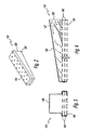
- Impingement duct 110 has housing 120, cover plate 130, and two columnating plates 140. Cover plate 130 and columnating plates 140 have a plurality of orifices disposed thereon. Housing 120 has opening 125 and optionally a plurality of air dams and air guides 127 disposed therein to assist with the even distribution of air throughout the duct 110.
- air enters duct 110 through opening 125, and is dispersed throughout housing 120. It then passes through columnating plates 140 and cover plate 130 before exiting duct 110 in columnated air jets.
- the present disclosure contemplates the use of 1 to 4 columnating plates.
- Fig. 5 an embodiment of the orifices is shown.
- the orifices in columnating plate 140 are arranged in three rows of circular shapes.
- the orifices in cover plate 130 are also arranged in three rows.
- the outer rows have orifices that are circular in shape, and the middle row has orifices shaped like crosses.
- the present disclosure contemplates a number of orientations and shapes for the orifices in the cover plate 130 and columnating plate 140.
- Such shapes can include, but are not limited to, rectangles, squares, diamonds, polygonal shapes, or any other shape suitable for such a purpose. As previously discussed, these shapes can have an area equivalent to a circular orifice having the disclosed diameters.
- the orifices in both the columnating and cover plates can be of varying sizes.
- FIGs. 6 and 7 profiles of air exiting orifices of the present disclosure and the prior art are shown.
- a columnated air jet of the present disclosure is shown hitting a flat surface.
- the larger orifices provide air jets that, while moving at a slower velocity overall, provide better contact with the surface to be heated.
- Fig. 7 which is an air flow diagram of an air jet of the prior art, the air flow is such that there is a stagnation region on the surface of the product to be heated, where no air flows directly onto the product. The product is thus heated less efficiently, producing an undesirable result.
- the orifices in the columnating plate 140 can be smaller than the corresponding orifices in the cover plate 130. This relationship helps to create a wider jet, and a larger area of contact with the food product.
- the ratio of the diameter of the columnating plate orifice to the diameter of the cover plate orifice is from 4:5 to 4:16, and is preferably 5:7.
- the present disclosure also contemplates columnating plate orifices that are larger or the same size as the orifices in the cover plate.
- the present disclosure also contemplates using the larger orifices previously discussed, in ovens that have impinging jets with heat transfer rates that vary throughout the oven.
- the heat transferred to the food product can be applied in steps, to match the product's ability to accept energy per unit of time.
- the heat transfer rates of the air ducts in an oven can be varied to provide higher or lower rates of heat transfer at different points along the conveyor within the oven.
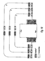
- Fig. 9 Such a configuration is shown in Fig. 9 .
- the air jets can be partially or completely shut off to alter the heat transfer rate to the food product.
- Fig. 9 the embodiment shown in Fig.
- the air jets of this embodiment can have any number of varying capacities other than the specific arrangement shown.
- the cover plates of the air ducts can be covered with mechanical structures to achieve the desired capacity.
- the unexpected result of the present disclosure is that using larger orifices helps to cook the food products more efficiently. This is an inversion of the commonly understood relationship between orifice size and cooking capacity. As a result, higher temperatures can be used with the orifices, without burning the surface of the food product. In addition, although the mass flow coming out of the air jets is high, the velocity is low enough so that the surface of the food product is not disturbed.
- the orifices of the present disclosure can increase the heating efficiency of the oven by up to 40% over currently available ovens, which can provide up to a 40% reduction in the amount of floor space taken up by the oven to maintain equal capacity.
- Figs. 10-17 Examples of food products cooked using the ovens having the standard size orifices and the larger orifices of the present invention are shown in Figs. 10-17 .
- the food products shown in Figs. 10-13 were cooked at 249°C (480°F) for 7 minutes, and the ovens used had impinging jets having 90 orifices at a diameter of 1,111 cm (7/16"). These food products, while acceptable, have crust and toppings that are at the maximum acceptable color.
- the food products shown in Figs. 14-17 by contrast, bake for 5.5 minutes at 260°C (500°F), or at 4.5 minutes at 271°C (520°F).
- the impinging jets of this oven had 22 orifices at a diameter of 2,223 cm (7/8").
- the crust and toppings of these food products are at a color that is in the middle of acceptable ranges.
- the products cooked using the orifices of the present disclosure are preferable.
- FIG 18 Another benefit provided by the orifices of the present disclosure is illustrated in Figure 18 .
- ovens using the orifices of the present disclosure (referred to as “FastBake” in the diagram) exhibit significantly lower noise readings at various points around the oven than ovens using the standard orifices. This can be highly advantageous in the applications where the oven is used.
- the orifices and air ducts of the present disclosure can be used with any number of air sources to supply air to the air jets.
- air sources may include, but are not limited to, axial flow fans, centrifugal flow fans, variable speed fans, multiple fans having fixed or variable speeds, any flow means capable of supplying air to the impingement duct, or any other suitable methods of providing air for such a use.
- the energy sources used to provide heat can be, but are not limited to, modulating energy sources and heating controls, power burners, tube burners, powered tube burners, electrical heat sources, powered ceramic burners, or burners with a heat exchanger or other suitable combustion or electrical source.
- alternate and supplemental sources of energy can be used in the oven, such as, but not limited to, infrared energy with a tubular heater, infrared energy with a reflected plate radiator, saturated steam energy to enhance the orifice energy, supersaturated steam energy to enhance the orifice energy, moisture combined with the orifice energy, moisture injected into the orifice energy space, low frequency microwave energy to enhance the orifice energy, and high frequency microwave energy to enhance the orifice energy.
- the oven of the present disclosure can also have a closable inlet and outlet, or an active air curtain located at the entrance and exit of the oven, to reduce energy losses.
- the orifices of the present disclosure may be perpendicular to the food products, or may be disposed at an angle to the food product, depending on the desired cooking effect. A preferred range of angles may be zero degrees to forty-five degrees from the perpendicular direction.
- the oven may also have one or more conveyors, which are configured to move food products at a higher or lower position with respect to the air jets during travel.
- the oven conveyor surface may also have a pitch spacing to facilitate optimal heat transfer to the food product or utensil in which the food product is cooked.
Applications Claiming Priority (2)
| Application Number | Priority Date | Filing Date | Title |
|---|---|---|---|
| US85148406P | 2006-10-13 | 2006-10-13 | |
| PCT/US2007/021840 WO2008048497A2 (en) | 2006-10-13 | 2007-10-12 | Impinging air ovens having high mass flow orifices |
Publications (3)
| Publication Number | Publication Date |
|---|---|
| EP2074369A2 EP2074369A2 (en) | 2009-07-01 |
| EP2074369A4 EP2074369A4 (en) | 2010-04-21 |
| EP2074369B1 true EP2074369B1 (en) | 2015-12-23 |
Family
ID=39314607
Family Applications (1)
| Application Number | Title | Priority Date | Filing Date |
|---|---|---|---|
| EP07839497.0A Not-in-force EP2074369B1 (en) | 2006-10-13 | 2007-10-12 | Impinging air ovens having high mass flow orifices |
Country Status (11)
| Country | Link |
|---|---|
| US (1) | US9089142B2 (zh) |
| EP (1) | EP2074369B1 (zh) |
| JP (1) | JP2010506565A (zh) |
| KR (1) | KR20090067206A (zh) |
| CN (1) | CN101589283B (zh) |
| AU (1) | AU2007313345B2 (zh) |
| CA (1) | CA2665822C (zh) |
| HK (1) | HK1135171A1 (zh) |
| SG (1) | SG175613A1 (zh) |
| WO (1) | WO2008048497A2 (zh) |
| ZA (1) | ZA200902418B (zh) |
Families Citing this family (17)
| Publication number | Priority date | Publication date | Assignee | Title |
|---|---|---|---|---|
| US8839527B2 (en) | 2006-02-21 | 2014-09-23 | Goji Limited | Drying apparatus and methods and accessories for use therewith |
| US10674570B2 (en) | 2006-02-21 | 2020-06-02 | Goji Limited | System and method for applying electromagnetic energy |
| US8653482B2 (en) | 2006-02-21 | 2014-02-18 | Goji Limited | RF controlled freezing |
| EP3010309B1 (en) | 2006-02-21 | 2019-04-10 | Goji Limited | Electromagnetic heating |
| US8075304B2 (en) * | 2006-10-19 | 2011-12-13 | Wayne/Scott Fetzer Company | Modulated power burner system and method |
| US9131543B2 (en) | 2007-08-30 | 2015-09-08 | Goji Limited | Dynamic impedance matching in RF resonator cavity |
| US20120122072A1 (en) | 2008-11-10 | 2012-05-17 | Rf Dynamics Ltd. | Method and system for heating and/or thawing blood products |
| KR101584397B1 (ko) | 2009-11-10 | 2016-01-11 | 고지 엘티디. | Rf 에너지를 사용하여 가열하기 위한 장치 및 방법 |
| JP6012107B2 (ja) | 2010-05-03 | 2016-10-25 | ゴジ リミテッド | 空間的に制御されたエネルギ送出 |
| US8703226B2 (en) * | 2010-10-14 | 2014-04-22 | Frito-Lay North America, Inc. | Method for improving the textural attributes of baked snack foods |
| DE102013223030B4 (de) * | 2013-11-12 | 2020-12-17 | Kaak Groep B.V. | Backofen und Nachrüstsatz für Backöfen |
| EP3183504A1 (en) * | 2014-08-19 | 2017-06-28 | Cleveland Range, LLC | A system to prevent incorrect finger placement in conveyor ovens |
| US9879865B2 (en) * | 2015-06-08 | 2018-01-30 | Alto-Shaam, Inc. | Cooking oven |
| NZ746496A (en) * | 2016-03-09 | 2021-12-24 | Dmp Entpr Pty Ltd | Conveyor-type oven |
| WO2018090101A1 (en) * | 2016-11-21 | 2018-05-24 | Domino's Pizza Enterprises Limited | Apparatus and method for reducing cooking time |
| CN110522319A (zh) * | 2019-10-18 | 2019-12-03 | 广东美的白色家电技术创新中心有限公司 | 烹饪器具 |
| CN215305176U (zh) * | 2021-06-15 | 2021-12-28 | 江门市新会恒隆家居创新用品有限公司 | 多士炉 |
Family Cites Families (27)
| Publication number | Priority date | Publication date | Assignee | Title |
|---|---|---|---|---|
| US4066011A (en) | 1971-09-13 | 1978-01-03 | Ballentine Earle W | Apparatus for thawing frozen food |
| US3884213A (en) | 1973-03-30 | 1975-05-20 | Donald P Smith | Cooking apparatus |
| US4338911A (en) | 1976-05-19 | 1982-07-13 | Smith Donald P | Cooking apparatus |
| US4492839A (en) * | 1976-05-19 | 1985-01-08 | Smith Donald P | Thermal treatment apparatus |
| US4479776A (en) | 1981-07-22 | 1984-10-30 | Smith Donald P | Thermal treatment of food products |
| US4154861A (en) | 1976-05-19 | 1979-05-15 | Smith Donald P | Heat treatment of food products |
| US4626661A (en) | 1984-04-16 | 1986-12-02 | Lincoln Manufacturing Company, Inc. | Air delivery system for an impingement food preparation oven |
| US4750276A (en) * | 1984-05-10 | 1988-06-14 | Donald Paul Smith | Impingement thermal treatment apparatus with collector plate |
| US4701340A (en) | 1985-12-09 | 1987-10-20 | Lincoln Foodservice Products, Inc. | Impingement and steam oven apparatus for preparing food products |
| US4781169A (en) * | 1987-04-14 | 1988-11-01 | Lincoln Foodservice Products, Inc. | Oven with radiant panel |
| US4834063A (en) | 1987-05-28 | 1989-05-30 | Stein Associates, Inc. | Food cooking oven with duct fingers and method |
| JPH02503386A (ja) * | 1988-03-10 | 1990-10-18 | ピッツァ ハット インコーポレーテッド | ピザを焼く方法及びオーブン |
| US4991497A (en) | 1989-07-10 | 1991-02-12 | Kfc Corporation | Method and apparatus for simulating open flame broiled meat products |
| CA2024203C (en) | 1989-09-22 | 2002-07-30 | Donald P. Smith | Balanced air return convection oven |
| US6041398A (en) | 1992-06-26 | 2000-03-21 | International Business Machines Corporation | Massively parallel multiple-folded clustered processor mesh array |
| US5205274A (en) * | 1989-09-22 | 1993-04-27 | Patentsmith Ii, Inc. | Turntable convection oven |
| US5401940A (en) * | 1990-01-10 | 1995-03-28 | Patentsmith Ii, Inc. | Oscillating air dispensers for microwave oven |
| US5025775A (en) | 1990-06-04 | 1991-06-25 | Lincoln Foodservice Products, Inc. | Air delivery system and oven control circuitry cooling system for a low profile impingement oven |
| WO1998008402A1 (en) * | 1996-08-30 | 1998-03-05 | Societe Des Produits Nestle S.A. | Nutritional formula for phenylketonuria patients |
| EP1149261B1 (en) * | 1998-05-23 | 2007-10-10 | Enersyst Development Center, L.L.C. | High heat transfer rate convection oven with grease management and smoke reduction capabilities |
| US6526961B1 (en) | 2000-07-10 | 2003-03-04 | Lincoln Foodservice Products, Inc | Conveyor oven |
| NZ535478A (en) | 2002-03-27 | 2006-03-31 | Enodis Corp | Conveyorized oven with moisture laden air impingement and method |
| CA2528539C (en) * | 2003-06-10 | 2009-09-22 | Lincoln Foodservice Products, Inc. | A high speed cooking oven having an air impingement heater with an improved orifice configuration |
| US7343912B2 (en) | 2003-09-16 | 2008-03-18 | Lincoln Foodservice Products Llc | Conveyor oven with improved air return and method |
| US6833533B1 (en) | 2004-03-12 | 2004-12-21 | Wolfe Electric, Inc. | Air impingement conveyor over |
| WO2008021243A2 (en) * | 2006-08-15 | 2008-02-21 | Lincoln Foodservice Products Llc | Multiple air dam device |
| WO2008106314A1 (en) | 2007-03-01 | 2008-09-04 | Osram Sylvania Inc. | Method of producing uv-emitting magnesium pentaborate phosphors |
-
2007
- 2007-10-12 CN CN2007800382343A patent/CN101589283B/zh not_active Expired - Fee Related
- 2007-10-12 US US11/974,274 patent/US9089142B2/en not_active Expired - Fee Related
- 2007-10-12 CA CA2665822A patent/CA2665822C/en not_active Expired - Fee Related
- 2007-10-12 AU AU2007313345A patent/AU2007313345B2/en not_active Ceased
- 2007-10-12 JP JP2009532433A patent/JP2010506565A/ja active Pending
- 2007-10-12 EP EP07839497.0A patent/EP2074369B1/en not_active Not-in-force
- 2007-10-12 ZA ZA200902418A patent/ZA200902418B/xx unknown
- 2007-10-12 SG SG2011074168A patent/SG175613A1/en unknown
- 2007-10-12 WO PCT/US2007/021840 patent/WO2008048497A2/en active Application Filing
- 2007-10-12 KR KR1020097009687A patent/KR20090067206A/ko not_active Application Discontinuation
-
2010
- 2010-04-13 HK HK10103584.4A patent/HK1135171A1/xx not_active IP Right Cessation
Also Published As
| Publication number | Publication date |
|---|---|
| WO2008048497A8 (en) | 2009-07-23 |
| AU2007313345A1 (en) | 2008-04-24 |
| US9089142B2 (en) | 2015-07-28 |
| HK1135171A1 (en) | 2010-05-28 |
| JP2010506565A (ja) | 2010-03-04 |
| US20080087175A1 (en) | 2008-04-17 |
| AU2007313345B2 (en) | 2011-12-08 |
| CA2665822C (en) | 2012-12-18 |
| EP2074369A4 (en) | 2010-04-21 |
| EP2074369A2 (en) | 2009-07-01 |
| WO2008048497A2 (en) | 2008-04-24 |
| ZA200902418B (en) | 2010-07-28 |
| CN101589283A (zh) | 2009-11-25 |
| CN101589283B (zh) | 2011-11-16 |
| CA2665822A1 (en) | 2008-04-24 |
| WO2008048497A3 (en) | 2008-06-12 |
| SG175613A1 (en) | 2011-11-28 |
| KR20090067206A (ko) | 2009-06-24 |
Similar Documents
| Publication | Publication Date | Title |
|---|---|---|
| EP2074369B1 (en) | Impinging air ovens having high mass flow orifices | |
| EP2139341B1 (en) | Compact conveyor oven | |
| EP1797758B1 (en) | Continuous cooking oven system | |
| US6805112B2 (en) | Convection oven having multiple airflow patterns | |
| US7424848B2 (en) | High speed cooking device and method | |
| EP0086568B1 (en) | Thermal treatment of food products | |
| EP0094816B1 (en) | Apparatus and method for heating food products | |
| US8029274B2 (en) | Convection oven with laminar airflow and method | |
| US8646383B1 (en) | Spiral oven apparatus and method of cooking | |
| WO2003082024A1 (en) | Conveyorized oven with moisture laden air impingement and method | |
| CA2595820A1 (en) | High efficiency fluid delivery system | |
| US5541390A (en) | Tunnel oven for microwave heating and cooking foods | |
| WO2018010000A1 (en) | Methods and apparatus for cooking food | |
| GB2217969A (en) | Travelling bread ovens | |
| CS263898B1 (cs) | Přívod horkého plynu do pracovního prostoru pece na tepelné opracování potravinářských výrobků |
Legal Events
| Date | Code | Title | Description |
|---|---|---|---|
| PUAI | Public reference made under article 153(3) epc to a published international application that has entered the european phase |
Free format text: ORIGINAL CODE: 0009012 |
|
| 17P | Request for examination filed |
Effective date: 20090513 |
|
| AK | Designated contracting states |
Kind code of ref document: A2 Designated state(s): AT BE BG CH CY CZ DE DK EE ES FI FR GB GR HU IE IS IT LI LT LU LV MC MT NL PL PT RO SE SI SK TR |
|
| AX | Request for extension of the european patent |
Extension state: AL BA HR MK RS |
|
| DAX | Request for extension of the european patent (deleted) | ||
| A4 | Supplementary search report drawn up and despatched |
Effective date: 20100322 |
|
| 17Q | First examination report despatched |
Effective date: 20100721 |
|
| GRAP | Despatch of communication of intention to grant a patent |
Free format text: ORIGINAL CODE: EPIDOSNIGR1 |
|
| INTG | Intention to grant announced |
Effective date: 20150618 |
|
| GRAS | Grant fee paid |
Free format text: ORIGINAL CODE: EPIDOSNIGR3 |
|
| GRAA | (expected) grant |
Free format text: ORIGINAL CODE: 0009210 |
|
| AK | Designated contracting states |
Kind code of ref document: B1 Designated state(s): AT BE BG CH CY CZ DE DK EE ES FI FR GB GR HU IE IS IT LI LT LU LV MC MT NL PL PT RO SE SI SK TR |
|
| REG | Reference to a national code |
Ref country code: GB Ref legal event code: FG4D |
|
| REG | Reference to a national code |
Ref country code: CH Ref legal event code: EP |
|
| REG | Reference to a national code |
Ref country code: IE Ref legal event code: FG4D |
|
| REG | Reference to a national code |
Ref country code: AT Ref legal event code: REF Ref document number: 766736 Country of ref document: AT Kind code of ref document: T Effective date: 20160115 |
|
| REG | Reference to a national code |
Ref country code: DE Ref legal event code: R096 Ref document number: 602007044321 Country of ref document: DE |
|
| REG | Reference to a national code |
Ref country code: LT Ref legal event code: MG4D |
|
| REG | Reference to a national code |
Ref country code: NL Ref legal event code: MP Effective date: 20151223 |
|
| PG25 | Lapsed in a contracting state [announced via postgrant information from national office to epo] |
Ref country code: LT Free format text: LAPSE BECAUSE OF FAILURE TO SUBMIT A TRANSLATION OF THE DESCRIPTION OR TO PAY THE FEE WITHIN THE PRESCRIBED TIME-LIMIT Effective date: 20151223 |
|
| REG | Reference to a national code |
Ref country code: AT Ref legal event code: MK05 Ref document number: 766736 Country of ref document: AT Kind code of ref document: T Effective date: 20151223 |
|
| PG25 | Lapsed in a contracting state [announced via postgrant information from national office to epo] |
Ref country code: FI Free format text: LAPSE BECAUSE OF FAILURE TO SUBMIT A TRANSLATION OF THE DESCRIPTION OR TO PAY THE FEE WITHIN THE PRESCRIBED TIME-LIMIT Effective date: 20151223 Ref country code: GR Free format text: LAPSE BECAUSE OF FAILURE TO SUBMIT A TRANSLATION OF THE DESCRIPTION OR TO PAY THE FEE WITHIN THE PRESCRIBED TIME-LIMIT Effective date: 20160324 Ref country code: SE Free format text: LAPSE BECAUSE OF FAILURE TO SUBMIT A TRANSLATION OF THE DESCRIPTION OR TO PAY THE FEE WITHIN THE PRESCRIBED TIME-LIMIT Effective date: 20151223 Ref country code: NL Free format text: LAPSE BECAUSE OF FAILURE TO SUBMIT A TRANSLATION OF THE DESCRIPTION OR TO PAY THE FEE WITHIN THE PRESCRIBED TIME-LIMIT Effective date: 20151223 Ref country code: LV Free format text: LAPSE BECAUSE OF FAILURE TO SUBMIT A TRANSLATION OF THE DESCRIPTION OR TO PAY THE FEE WITHIN THE PRESCRIBED TIME-LIMIT Effective date: 20151223 |
|
| PG25 | Lapsed in a contracting state [announced via postgrant information from national office to epo] |
Ref country code: IT Free format text: LAPSE BECAUSE OF FAILURE TO SUBMIT A TRANSLATION OF THE DESCRIPTION OR TO PAY THE FEE WITHIN THE PRESCRIBED TIME-LIMIT Effective date: 20151223 Ref country code: ES Free format text: LAPSE BECAUSE OF FAILURE TO SUBMIT A TRANSLATION OF THE DESCRIPTION OR TO PAY THE FEE WITHIN THE PRESCRIBED TIME-LIMIT Effective date: 20151223 Ref country code: CZ Free format text: LAPSE BECAUSE OF FAILURE TO SUBMIT A TRANSLATION OF THE DESCRIPTION OR TO PAY THE FEE WITHIN THE PRESCRIBED TIME-LIMIT Effective date: 20151223 |
|
| PG25 | Lapsed in a contracting state [announced via postgrant information from national office to epo] |
Ref country code: PT Free format text: LAPSE BECAUSE OF FAILURE TO SUBMIT A TRANSLATION OF THE DESCRIPTION OR TO PAY THE FEE WITHIN THE PRESCRIBED TIME-LIMIT Effective date: 20160426 Ref country code: PL Free format text: LAPSE BECAUSE OF FAILURE TO SUBMIT A TRANSLATION OF THE DESCRIPTION OR TO PAY THE FEE WITHIN THE PRESCRIBED TIME-LIMIT Effective date: 20151223 Ref country code: AT Free format text: LAPSE BECAUSE OF FAILURE TO SUBMIT A TRANSLATION OF THE DESCRIPTION OR TO PAY THE FEE WITHIN THE PRESCRIBED TIME-LIMIT Effective date: 20151223 Ref country code: EE Free format text: LAPSE BECAUSE OF FAILURE TO SUBMIT A TRANSLATION OF THE DESCRIPTION OR TO PAY THE FEE WITHIN THE PRESCRIBED TIME-LIMIT Effective date: 20151223 Ref country code: IS Free format text: LAPSE BECAUSE OF FAILURE TO SUBMIT A TRANSLATION OF THE DESCRIPTION OR TO PAY THE FEE WITHIN THE PRESCRIBED TIME-LIMIT Effective date: 20160423 Ref country code: SK Free format text: LAPSE BECAUSE OF FAILURE TO SUBMIT A TRANSLATION OF THE DESCRIPTION OR TO PAY THE FEE WITHIN THE PRESCRIBED TIME-LIMIT Effective date: 20151223 Ref country code: RO Free format text: LAPSE BECAUSE OF FAILURE TO SUBMIT A TRANSLATION OF THE DESCRIPTION OR TO PAY THE FEE WITHIN THE PRESCRIBED TIME-LIMIT Effective date: 20151223 |
|
| REG | Reference to a national code |
Ref country code: DE Ref legal event code: R097 Ref document number: 602007044321 Country of ref document: DE |
|
| REG | Reference to a national code |
Ref country code: FR Ref legal event code: PLFP Year of fee payment: 10 |
|
| PLBE | No opposition filed within time limit |
Free format text: ORIGINAL CODE: 0009261 |
|
| STAA | Information on the status of an ep patent application or granted ep patent |
Free format text: STATUS: NO OPPOSITION FILED WITHIN TIME LIMIT |
|
| PG25 | Lapsed in a contracting state [announced via postgrant information from national office to epo] |
Ref country code: DK Free format text: LAPSE BECAUSE OF FAILURE TO SUBMIT A TRANSLATION OF THE DESCRIPTION OR TO PAY THE FEE WITHIN THE PRESCRIBED TIME-LIMIT Effective date: 20151223 |
|
| 26N | No opposition filed |
Effective date: 20160926 |
|
| PG25 | Lapsed in a contracting state [announced via postgrant information from national office to epo] |
Ref country code: BE Free format text: LAPSE BECAUSE OF FAILURE TO SUBMIT A TRANSLATION OF THE DESCRIPTION OR TO PAY THE FEE WITHIN THE PRESCRIBED TIME-LIMIT Effective date: 20151223 |
|
| PGFP | Annual fee paid to national office [announced via postgrant information from national office to epo] |
Ref country code: FR Payment date: 20161025 Year of fee payment: 10 Ref country code: GB Payment date: 20161027 Year of fee payment: 10 Ref country code: DE Payment date: 20161027 Year of fee payment: 10 |
|
| PG25 | Lapsed in a contracting state [announced via postgrant information from national office to epo] |
Ref country code: SI Free format text: LAPSE BECAUSE OF FAILURE TO SUBMIT A TRANSLATION OF THE DESCRIPTION OR TO PAY THE FEE WITHIN THE PRESCRIBED TIME-LIMIT Effective date: 20151223 |
|
| REG | Reference to a national code |
Ref country code: CH Ref legal event code: PL |
|
| REG | Reference to a national code |
Ref country code: IE Ref legal event code: MM4A |
|
| PG25 | Lapsed in a contracting state [announced via postgrant information from national office to epo] |
Ref country code: LI Free format text: LAPSE BECAUSE OF NON-PAYMENT OF DUE FEES Effective date: 20161031 Ref country code: CH Free format text: LAPSE BECAUSE OF NON-PAYMENT OF DUE FEES Effective date: 20161031 |
|
| PG25 | Lapsed in a contracting state [announced via postgrant information from national office to epo] |
Ref country code: LU Free format text: LAPSE BECAUSE OF NON-PAYMENT OF DUE FEES Effective date: 20161012 |
|
| PG25 | Lapsed in a contracting state [announced via postgrant information from national office to epo] |
Ref country code: IE Free format text: LAPSE BECAUSE OF NON-PAYMENT OF DUE FEES Effective date: 20161012 |
|
| REG | Reference to a national code |
Ref country code: DE Ref legal event code: R119 Ref document number: 602007044321 Country of ref document: DE |
|
| PG25 | Lapsed in a contracting state [announced via postgrant information from national office to epo] |
Ref country code: HU Free format text: LAPSE BECAUSE OF FAILURE TO SUBMIT A TRANSLATION OF THE DESCRIPTION OR TO PAY THE FEE WITHIN THE PRESCRIBED TIME-LIMIT; INVALID AB INITIO Effective date: 20071012 Ref country code: CY Free format text: LAPSE BECAUSE OF FAILURE TO SUBMIT A TRANSLATION OF THE DESCRIPTION OR TO PAY THE FEE WITHIN THE PRESCRIBED TIME-LIMIT Effective date: 20151223 |
|
| GBPC | Gb: european patent ceased through non-payment of renewal fee |
Effective date: 20171012 |
|
| PG25 | Lapsed in a contracting state [announced via postgrant information from national office to epo] |
Ref country code: TR Free format text: LAPSE BECAUSE OF FAILURE TO SUBMIT A TRANSLATION OF THE DESCRIPTION OR TO PAY THE FEE WITHIN THE PRESCRIBED TIME-LIMIT Effective date: 20151223 Ref country code: MC Free format text: LAPSE BECAUSE OF FAILURE TO SUBMIT A TRANSLATION OF THE DESCRIPTION OR TO PAY THE FEE WITHIN THE PRESCRIBED TIME-LIMIT Effective date: 20151223 Ref country code: MT Free format text: LAPSE BECAUSE OF NON-PAYMENT OF DUE FEES Effective date: 20161031 |
|
| REG | Reference to a national code |
Ref country code: FR Ref legal event code: ST Effective date: 20180629 |
|
| PG25 | Lapsed in a contracting state [announced via postgrant information from national office to epo] |
Ref country code: DE Free format text: LAPSE BECAUSE OF NON-PAYMENT OF DUE FEES Effective date: 20180501 Ref country code: GB Free format text: LAPSE BECAUSE OF NON-PAYMENT OF DUE FEES Effective date: 20171012 Ref country code: BG Free format text: LAPSE BECAUSE OF FAILURE TO SUBMIT A TRANSLATION OF THE DESCRIPTION OR TO PAY THE FEE WITHIN THE PRESCRIBED TIME-LIMIT Effective date: 20151223 |
|
| PG25 | Lapsed in a contracting state [announced via postgrant information from national office to epo] |
Ref country code: FR Free format text: LAPSE BECAUSE OF NON-PAYMENT OF DUE FEES Effective date: 20171031 |