EP0094816B1 - Apparatus and method for heating food products - Google Patents
Apparatus and method for heating food products Download PDFInfo
- Publication number
- EP0094816B1 EP0094816B1 EP83302737A EP83302737A EP0094816B1 EP 0094816 B1 EP0094816 B1 EP 0094816B1 EP 83302737 A EP83302737 A EP 83302737A EP 83302737 A EP83302737 A EP 83302737A EP 0094816 B1 EP0094816 B1 EP 0094816B1
- Authority
- EP
- European Patent Office
- Prior art keywords
- air
- food products
- cavity
- scroll
- heating
- Prior art date
- Legal status (The legal status is an assumption and is not a legal conclusion. Google has not performed a legal analysis and makes no representation as to the accuracy of the status listed.)
- Expired
Links
Images


Classifications
-
- A—HUMAN NECESSITIES
- A21—BAKING; EDIBLE DOUGHS
- A21B—BAKERS' OVENS; MACHINES OR EQUIPMENT FOR BAKING
- A21B1/00—Bakers' ovens
- A21B1/02—Bakers' ovens characterised by the heating arrangements
- A21B1/24—Ovens heated by media flowing therethrough
- A21B1/245—Ovens heated by media flowing therethrough with a plurality of air nozzles to obtain an impingement effect on the food
-
- A—HUMAN NECESSITIES
- A21—BAKING; EDIBLE DOUGHS
- A21B—BAKERS' OVENS; MACHINES OR EQUIPMENT FOR BAKING
- A21B1/00—Bakers' ovens
- A21B1/42—Bakers' ovens characterised by the baking surfaces moving during the baking
- A21B1/48—Bakers' ovens characterised by the baking surfaces moving during the baking with surfaces in the form of an endless band
Definitions
- the present invention relates generally to arrangements for heating food products, and more particularly to an apparatus and method for heating food products by convection.
- the chamber of most typical commercial ovens is only accessible from one side, usually through a hinged door or the like. This not only mandates that the oven be repeatedly opened and closed for removing cooked products from the oven or for placing food products to be cooked into the oven, but also detracts from convenient use of the oven since individual orders being prepared in the oven can sometimes be mixed-up. Naturally, this detracts from efficient food preparation, and may result in customer dissatisfaction.
- a further drawback associated with the typical commercial oven relates to the manner in which the oven cooks or heats food. While the normal baking process by which a conventional oven cooks is well established as providing acceptable results, the period of time required for the required cooking or heating may be unacceptably long for some food service establishments. This is especially true for fast food restaurants and the like in which a premium is placed upon quick and efficient preparation of food products. In this regard, arrangements for heating food by forced hot air convection have been recognized as desirable for reducing food preparation time.
- DE-A-2 400 845 describes an oven provided with a heater and a fan which is driven to circulate the hot gases in the oven over the foodstuff.
- DE-A-2 312 722 goes still further in providing an apparatus for heating food products in accordance with the preamble of claim 1 of this application and comprising a housing having a cavity adapted to receive said food products, and heating means for heating said cavity, means for conveying food products through said cavity, foraminous plate means disposed above and below said cavity, centrifugal blower means for circulating air drawn from said cavity and over said heating means through said foraminous plate means, and duct means associated with the blower means for guiding air flow from said circulating means to said foraminous plate means, whereby heated air passes through said foraminous plate means and heats said food products.
- An apparatus for heating food products as described in DE-A-2 312 722 overcomes many of the inherent limitations associated with conventional oven arrangement, and is readily suited for use in commercial restaurant establishments. Nevertheless, such apparatus is capable of improvement to provide for the still more efficient and economical preparation of food products.
- the present invention is characterized in that said duct means defines scroll-shaped air passage means for aerodynamically enhancing said air flow of the circulated air and venturi means disposed downstream of said air passage means and upstream of said foraminous plate means for creating a relative increase in the pressure of the circulated air immediately upstream of said plate means for its injection through said plate means for heating said food products, said scroll-shaped air passage means comprising a pair of scroll-shaped passages associated with said centrifugal blower means and arranged to respectively duct circulated air above and below said cavity for passage through said plate means.
- the flow rate of the heating air is increased and the uniformity of heating is improved and also the interject turbulence, so that faster, better and more economical results are achieved.
- the present invention also provides a method of heating food products by convection including conveying said food products through a cavity in a housing defined between respective upper and lower foraminous plate means, circulating selectively heated air within said housing by drawing air from within said cavity with centrifugal blower means and directing the circulated air through said upper and lower plate means to heat said food products, characterized by aerodynamically enhancing the flow of the circulated air from said blower means towards both said upper and said lower plate means using generally scroll-shaped passage means in close association with said centrifugal blower means, and passing the aerodynamically enhanced air flow through venturi means downstream of the scroll-shaped passage means so as to create a relative increase in the pressure of the circulated air immediately upstream of said plate means for its injection through said plate means.
- a tunnel heater apparatus typically includes a heater housing having a tunnel-like cavity extending throughout its length, the cavity being adapted to receive food products to be heated. Conveying means are provided which extend the length of the cavity in the housing for supporting and conveying food products through the heater so that the products are received by one end of the cavity and discharged from the other end.
- the apparatus further includes upper and lower foraminous plates which are disposed within the heater housing above and below the tunnel-like cavity. Each plate is flat and relatively thin, and includes a plurality of holes extending therethrough through which air is directed against food products in the cavity.
- Each plate includes adjacent perforate and imperforate portions so that food products being heated are conveyed through non-discrete zones of relatively high and relatively low convective heating.
- centrifugal blower means are provided for drawing air from the heater cavity.
- a pair of centrifugal blowers are provided, each run by its own electric motor.
- a thermostatically controlled burner positioned within the heating chamber heats the circulated air to an elevated temperature so that food products conveyed through the heater cavity are heated by convection.
- the apparatus includes a duct work arrangement to facilitate air flow.
- Aerodynamically efficient duct means are associated with the air circulating blowers for enhancing air flow and delivery from the blowers to the foraminous upper and lower plates positioned above and below the heater cavity.
- the duct means define a pair of opposed scroll-shaped passages around each of the blowers of the heater, and further define venturi-like passages disposed immediately upstream of the foraminous plates for creating a relative increase in the pressure of the circulated air before passage through the upper and lower plates.
- the duct work further includes arcuate- shaped air flow guides which are positioned within the scroll-shaped passages for guiding the flow of circulated air transversely of the scroll-shaped passages to the venturi-like passages downstream thereof.
- This arrangement of the duct work of the present heater apparatus has been found to promote efficient air flow so that food products are heated quickly and efficiently.
- the present tunnel heater includes a plurality of supports which support the duct work of the heater within the heater housing. Each of the supports includes a portion of reduced cross-section so that conductive heat transfer from the heater duct work to outer portions of the heater housing is minimized.
- This duct-supporting arrangement, together with the use of suitable thermally insulating materials, has been found to promote energy efficiency, an important consideration in a commercially-sized cooking device.
- An apparatus and method in accordance with the present invention obviates many of the problems associated with typical large-sized ovens heretofore commonly used in commercial food preparation.
- the conveying of the food products to be heated through a cavity into which heated air is introduced assures systematic and convenient filling of food orders and provides much shorter cooking times than required with use of conventional ovens.
- the apparatus may be brought up to operating temperatures in a relatively short time, thus precluding the need for the apparatus to be maintained in a fully operational state during periods in which maximum output is not required.
- the tunnel heater 10 is arranged to cook or otherwise heat food products by forced hot air convection, and includes a food product conveying arrangement so that food products to be heated may be automatically moved through the heater for cooking.
- Tunnel heater 10 includes a generally box-like heater housing 12 supported upon legs 14. Notably, heater 10 is designed so that one heater can be stacked upon another, which is particularly useful where space is somewhat limited.
- Heater housing 12 includes an outer upper wall 16 and an outer lower wall 18. The housing further includes spaced outer side walls 20 and 22, and spaced outer end walls 24 and 26. Each of end walls 24 and 26 defines an opening at the respective ends of a tunnel-like cavity 28 which extends the length of heater 10.
- Cavity 28 is adapted to receive food products to be heated, and to this end a conveyor 30 is provided which extends the length of cavity 28 and beyond the ends thereof.
- Conveyor 30 includes an upper conveyor run 32 and a lower, return conveyor run 34 so that food products, such as 36, may be placed upon the upper conveyor run 32 and advanced through tunnel cavity 28 of the heater. In this manner, food products are received through one end of cavity 28, moved through the cavity on conveyor 30, and discharged from the conveyor at the other end of cavity 28.
- Conveyor 30 is preferably provided with a variable speed control so that heating times of food products conveyed can be selectively varied.
- outer side wall 20 of the heater housing 12 may be provided with an elongated observation window 38 so that food products being conveyed through the heater may be readily inspected.
- Window 38 may be provided with sliding glass doors or the like to permit ready access to tunnel cavity 28 intermediate the ends thereof.
- tunnel heater 10 provides for circulation of heated air within the heater housing 12 so that the heated air is directed against the upper and lower surfaces of food products conveyed through the heater.
- a pair of centrifugal blowers 40 is provided for drawing air from within cavity 28, although a single blower or more than two blowers could of course be used.
- Each blower 40 is provided with its own electric motor 42, with the blowers 40 arranged so that air drawn from cavity 28 is drawn into heating chamber 44 through a plurality of upper and lower intake holes 46 and 47 defined by a generally vertically disposed intake plate 48.
- heating chamber 44 is further defined by upper and lower duct plates 50 which are positioned generally above and below intake plate 48.
- Air drawn into heating chamber 44 is heated by a heater comprising a burner 52 which extends into the heating chamber.
- An electric heater can also be readily employed in the present tunnel heater.
- Burner 52 is preferably gas-fired, and is provided with a generally cylindrical flame tube 54 which extends into heating chamber 44 and within which combustion by the burner 52 takes place. Burner 52 operates to selectively heat air drawn through heating chamber 44 in response to thermostatically-regulated automatic controls, designated generally at 56.
- flame tube 54 minimizes direct impingement of heat energy from the burner on blowers 40 disposed immediately downstream of the heating chamber 44. Without flame tube 54, blowers 40 would otherwise tend to suck flames from burner 53 into the blower intakes.
- Circulated air heated within heating chamber 44 is drawn into centrifugal blowers 40 through respective blower intakes 58 which define the low pressure or suction side of each blower.
- the heated, circulating air is blown radially from the blowers 40 in blower chambers 60 within which each of blowers 40 is respectively disposed.
- blower chambers 60 The configuration of the blower chambers 60 is significant for providing aerodynamically efficient air flow as the circulating air is ducted from the blowers back to tunnel cavity 28.
- Each blower chamber 60 is defined by a respective end wall 62, and common top and bottom walls 64 and 66.
- the blower chambers are further defined by a common rear wall 68 which is spaced inwardly of outer side wall 22 of heater housing 12.
- suitable thermal insulation 69 is provided between outer side wall 22 and rear wall 68.
- a dividing wall 70 extends vertically from top wall 64 to bottom wall 66 and distinguishes the two blower chambers from each other.
- a plurality of arcuate plate arrangements 72 defines aerodynamically efficient, first and second pairs of generally scroll-shaped air flow passages 73, with each pair of passages in close association with and extending about a respective one of blowers 40.
- the passages 73 of each pair are generally opposed to each other, with each extending approximately halfway about the respective blower 40.
- the passages 73 of each pair are arranged for opposite blower discharge to substantially equally distribute and duct air from the respective blower 40 to upper and lower sides of tunnel cavity 28 for flow against food products in the cavity. This arrangement for ducting circulating air flow within tunnel heater 10 has been found to promote highly efficient operation, which provides for fast and readily-controllable heating of food products conveyed through tunnel cavity 28.
- Air from within the blower chambers 60 is circulated therefrom through upper and lower portions of discharge plate 74 to upper and lower air flow passages 77 and 79 (with blower intakes 58 disposed generally centrally of discharge plate 74).
- Discharge plate 74 defines a plurality of discharge openings 78, with each discharge opening 78 receiving flow from a respective one of scroll-shaped passages 73.
- This preferred arrangement of discharge plate 74 cooperates with the scroll-shaped passages 73 so that generally equal portions of the air circulated by each blower 40 are respectively channeled through either one of the upper or lower air flow passages 77 and 79 through which the air circulates.
- Air flow efficiency is enhanced by the provision of arcuate guides 80 which are positioned generally adjacent rear wall 68, and are arranged to guide the flow of circulating air through discharge plate 74 transversely of the scroll-shaped passages 73 which extend about blowers 40.
- the duct work of the present tunnel heater which defines upper and lower air flow passages 77 and 79 provides each of these passages with a venturi-like configuration for directing heated air from the blowers 40 back to the tunnel cavity 28 for heating food products.
- Upper and lower air flow passages 77 and 79 are respectively defined by upper and lower duct walls 82 and 84, which extend from discharge plate 74 and converge toward the opposite side of the heater housing 12.
- the upper and lower venturi-like airflow passages 77 and 79 are further defined by duct plates 50 disposed above and below intake plate 48 of heating chamber 44.
- arcuate guides 80 within blower chambers 60 act to guide circulating air from the scroll-shaped passages 73 about blowers 40 into the venturi-like air passages 77 and 79 downstream thereof.
- the present apparatus includes upper and lower foraminous plates 86 and 88.
- Upper and lower plates 86 and 88 are respectively disposed above and below and adjacent to tunnel cavity 28.
- Upper plate 86 and lower plate 88 are positioned inwardly of and between upper and lower intake holes 46 and 47 in intake plate 48.
- Intake holes 46 communicate with cavity 28 on the same side of the upper plate 86 that is associated with air passage 77.
- intake holes 47 communicate with cavity 28 on the same side of the lower plate 88 that is associated with air passage 79.
- Upper and lower plates 86 and 88 respectively extend from duct plates 50 to inner wall 90.
- the inner wall 90 is spaced from the outer side wall 20 of heater housing 12, with suitable thermal insulation provided therebetween for minimizing heat transfer from the heated circulating air to the heater housing.
- Each plate 86 and 88 is slidably supported by channels 94 and 96 which permit the plates to be easily removed for cleaning or servicing of the tunnel heater.
- each plate 86 and 88 includes at least one perforated portion 97, which includes a plurality of relatively closely spaced air passage holes 98, and at least one imperforate portion 99 adjacent perforated portion 97.
- each plate 86 and 88 includes a plurality of respectively vertically aligned perforated and imperforate portions 97 and 99 extending generally transversely to the path of food products conveyed through tunnel cavity 28.
- the food products are conveyed through generally adjacent, non-discrete, alternating zones or areas of relatively high and relatively low convective heating. Passage of food products through high and low heating zones in this manner is desirable since moisture in the food products being heated is permitted to migrate toward the surfaces of the products during passage of the products through the zones of relatively low convective heating. More uniform heating of the products thereby results, providing cooked products have improved quality and appeal.
- This method of heating food products is particularly effective for heating or baking products having crusts or the like, resulting in products having the desired texture and doneness throughout.
- upper and lower plates 86 and 88 can be made to provide different rates of heating of the upper and lower surfaces of the products by varying the size, number and distribution of holes in the plates.
- the relative spacing of food products from the plates 86 and 88 also affects the rate of product heating.
- products are conveyed through cavity 28 so that their surfaces are spaced between approximately one to three inches from the plates 86 and 88.
- relative spacing of conveyed products for optimum results will, of course, depend upon the configuration of plates 86 and 88, the rate and velocity of airflow against and about the products, and the temperature of the circulating air. These design parameters can be varied while still obtaining the desired efficient and readily controlled heating provided by the present apparatus.
- each plate 86 and 88 is fabricated from 18 gauge stainless steel and each hole 98 of perforated portions 97 is approximately 7,9 mm (5/16 of an inch) in diameter.
- Each perforated portion 97 includes six rows of holes 98 with adjacent holes of each row spaced on approximately 15,9 mm (5/8 inch) centers. Adjacent rows of holes 98 are staggered with respect to each other by approximately 3,2 mm (1/8 inch). While various other perforated configurations for foraminous upper and lower plates 86 and 88 can also be used, this particular sizing and spacing of holes 98 has been found to provide the desired high velocity, blanket-like flow of heated air against food products conveyed through tunnel cavity 28.
- the ducting of the heated circulating air through the venturi-like upper and lower air flow passages 77 and 79 creates a relative increase in the pressure of the circulated air upstream of upper and lower plates 88 and 86 before the air passes through the plates and is directed against food products for heating.
- the overall arrangement of the aerodynamically efficient duct work of the present tunnel heater greatly promotes efficient heating of food products.
- the efficient air flow provided by the present arrangement minimizes heat energy losses by passage of air from the open ends of tunnel cavity 28.
- the internal duct work of the tunnel heater is supported within the heater housing 12 so that conductive heat transfer from the heated circulating air to outer portions of the heater housing is minimized.
- supports 100 respectively extend between the upper and lower outer walls 16 and 18 of the heater housing 12 and top and bottom walls 64 and 66 about blower chambers 60 within the housing.
- Each support 100 includes a plurality of spaced holes 102 so that each support 100 includes a portion of reduced cross-section so that conductive heat transfer therethrough is minimized.
- supports 104 are provided extending between end wall 90 and upper and lower outer walls 16 and 18, with supports 104 each defining a plurality of holes 106 for providing each support with a portion of reduced cross-section for minimizing conductive heat transfer therethrough.
- supports such as 100 and 104 together with suitable thermal insulation, permits the outer surfaces of heater housing 12 to remain relatively cool even though air circulated within the heater may be heated to temperatures on the order of several hundred degrees Fahrenheit.
- each of two blowers 40 provided in the tunnel heater has a rated air flow capacity of approximately 35,4 m 3 /min (1250 cubic feet per minute) (CFM), with working air flow through each blower being approximately 21,2 m 3 /min (750 CFM).
- Upper and lower foraminous plates 86 and 88 each include two plate sections fitted side-by-side so that generally continuous upper and lower plates 86 and 88 are provided extending substantially the length of tunnel cavity 28.
- Each plate 86- and 88 includes six spaced perforated portions 97 having holes 98 spaced as described above.
- Circulating air is heated by burner 52 having a maximum rated output of approximately 105 500 kJ/h (100,000 BTU/hour), with the burner typically operating at a rate of 30,000-50,000 BTU/hour.
- Circulating air flow velocity within venturi-like air flow passages 77 and 79 reaches approximately 31650-52750 kJ/h (3800-4000 feet/minute) through the areas of reduced cross-section, with air velocity decreasing to approximately 427-488 m/min (1400-1600 feet/minute) upstream of foraminous plates 86 and 88.
- the velocity of air flow against food products in cavity 28 is on the order of approximately 549 ⁇ 610 m/min (1800-2000 feet/minute).
- This particular embodiment of the present tunnel heater has proven to provide highly acceptable results for commercial use. However, a wide variety of operating conditions can be readily provided in a heater apparatus made in accordance with the teachings herein.
- FIG. 7 a further embodiment for the circulating air duct work of the present heater is disclosed.
- This embodiment includes a different arrangement for the chambers within which blowers 40 are positioned which acts to enhance aerodynamically efficient air flow in a manner similar to the arrangement of blower chambers 60.
- Each blower chamber 160 is defined by a respective end wall 162, and common top and bottom walls 164 and 166.
- the blower chambers are further defined by a common rear wall 168 (spaced outwardly of outer side wall 22 of heater housing 12).
- a dividing wall 170 extends angularly from top wall 164 to bottom wall 166 and distinguishes the blower chambers 160 from each other.
- dividing wall 170 together with a plurality of arcuate plate arrangements 172, defines aerodynamically efficient, generally scroll-shaped air flow passages 173 which are closely associated with and respectively extend about the blowers 40.
- this arrangement of chambers 160 for ducting circulating air flow has been found to promote highly efficient operation.
- Air from within the blower chambers 160 is circulated therefrom through upper and lower portions of discharge plate 174 (positioned within heater 10 like discharge plate 74) to the upper and lower air flow passages 77 and 79.
- Discharge plate 174 defines discharge openings 178 and 179 through which air circulated by blowers 40 flows.
- Discharge plate 174 acts in cooperation with blower chambers 160 to baffle air flow from the blowers 40 for distribution to upper and lower air flow passages 77 and 79. If desired, the configuration of discharge plate 174 can be provided so that air flow from each blower 42 is evenly distributed between passages 77 and 79.
- a predominant portion of the air flow from one of the blowers can be directed to one of passages 77 and 79, with a predominant air flow from the other blower directed to the other of the passages 77 and 79.
- This latter flow distribution is achieved by sizing and positioning discharge openings 178 and 179 generally as illustrated.
- Other baffling arrangements can also be used.
- Air flow efficiency is enhanced by the provision of arcuate air flow guides 140 which are positioned generally adjacent rear wall 168, and are arranged to guide the flow of circulating air through discharge plate 174 transversely of the scroll-shaped passages 173 which respectively extend about each blower 40.
- a tunnel heater apparatus which greatly facilitates efficient heating and preparation of food products.
- the present arrangement not only heats food products in a relatively rapid fashion by the use of forced air convection for cooking, but is also energy efficient, with aerodynamically correct air flow passages promoting smooth and efficient circulation of heated air for heating food products.
Description
- The present invention relates generally to arrangements for heating food products, and more particularly to an apparatus and method for heating food products by convection.
- In the restaurant and food service industry, one of the primary considerations in providing efficient food preparation and service is the manner in which food products are to be cooked or otherwise heated. To this end, many establishments employ commercially-sized ovens and like devices which heat food in a conventional manner by placing the food within the heated oven chamber.
- While such cooking arrangements are in widespread use, such use is not without certain inherent drawbacks. For example, typical commercial ovens are generally designed to be continuously switched on, that is, the oven is heated to its normal operating temperature at the start of business hours and left to operate continuously throughout the business day. Unfortunately, this can detract from efficient operation of the unit since many restaurant establishments experience peaks in their business only during certain times while they are open, such as at meal times. Thus, there are periods during which the oven is switched on and ready for use when there is little or no business.
- Further, the chamber of most typical commercial ovens is only accessible from one side, usually through a hinged door or the like. This not only mandates that the oven be repeatedly opened and closed for removing cooked products from the oven or for placing food products to be cooked into the oven, but also detracts from convenient use of the oven since individual orders being prepared in the oven can sometimes be mixed-up. Naturally, this detracts from efficient food preparation, and may result in customer dissatisfaction.
- A further drawback associated with the typical commercial oven relates to the manner in which the oven cooks or heats food. While the normal baking process by which a conventional oven cooks is well established as providing acceptable results, the period of time required for the required cooking or heating may be unacceptably long for some food service establishments. This is especially true for fast food restaurants and the like in which a premium is placed upon quick and efficient preparation of food products. In this regard, arrangements for heating food by forced hot air convection have been recognized as desirable for reducing food preparation time.
- Thus, DE-A-2 400 845 describes an oven provided with a heater and a fan which is driven to circulate the hot gases in the oven over the foodstuff.
- DE-A-2 312 722 goes still further in providing an apparatus for heating food products in accordance with the preamble of claim 1 of this application and comprising a housing having a cavity adapted to receive said food products, and heating means for heating said cavity, means for conveying food products through said cavity, foraminous plate means disposed above and below said cavity, centrifugal blower means for circulating air drawn from said cavity and over said heating means through said foraminous plate means, and duct means associated with the blower means for guiding air flow from said circulating means to said foraminous plate means, whereby heated air passes through said foraminous plate means and heats said food products.
- An apparatus for heating food products as described in DE-A-2 312 722 overcomes many of the inherent limitations associated with conventional oven arrangement, and is readily suited for use in commercial restaurant establishments. Nevertheless, such apparatus is capable of improvement to provide for the still more efficient and economical preparation of food products.
- To this end and in accordance with one aspect, the present invention is characterized in that said duct means defines scroll-shaped air passage means for aerodynamically enhancing said air flow of the circulated air and venturi means disposed downstream of said air passage means and upstream of said foraminous plate means for creating a relative increase in the pressure of the circulated air immediately upstream of said plate means for its injection through said plate means for heating said food products, said scroll-shaped air passage means comprising a pair of scroll-shaped passages associated with said centrifugal blower means and arranged to respectively duct circulated air above and below said cavity for passage through said plate means.
- By the use of these features, the flow rate of the heating air is increased and the uniformity of heating is improved and also the interject turbulence, so that faster, better and more economical results are achieved.
- The present invention also provides a method of heating food products by convection including conveying said food products through a cavity in a housing defined between respective upper and lower foraminous plate means, circulating selectively heated air within said housing by drawing air from within said cavity with centrifugal blower means and directing the circulated air through said upper and lower plate means to heat said food products, characterized by aerodynamically enhancing the flow of the circulated air from said blower means towards both said upper and said lower plate means using generally scroll-shaped passage means in close association with said centrifugal blower means, and passing the aerodynamically enhanced air flow through venturi means downstream of the scroll-shaped passage means so as to create a relative increase in the pressure of the circulated air immediately upstream of said plate means for its injection through said plate means.
- Typically, in one embodiment of the invention, a tunnel heater apparatus includes a heater housing having a tunnel-like cavity extending throughout its length, the cavity being adapted to receive food products to be heated. Conveying means are provided which extend the length of the cavity in the housing for supporting and conveying food products through the heater so that the products are received by one end of the cavity and discharged from the other end. The apparatus further includes upper and lower foraminous plates which are disposed within the heater housing above and below the tunnel-like cavity. Each plate is flat and relatively thin, and includes a plurality of holes extending therethrough through which air is directed against food products in the cavity. Each plate includes adjacent perforate and imperforate portions so that food products being heated are conveyed through non-discrete zones of relatively high and relatively low convective heating. In order to circulate air within the heater housing through the foraminous plates, centrifugal blower means are provided for drawing air from the heater cavity. A pair of centrifugal blowers are provided, each run by its own electric motor. As circulating air is drawn from within the heater cavity into the centrifugal blowers, the air passes through a heating chamber in which the air is selectively heated. A thermostatically controlled burner positioned within the heating chamber heats the circulated air to an elevated temperature so that food products conveyed through the heater cavity are heated by convection. In order to enhance efficient circulation of air within the heater, the apparatus includes a duct work arrangement to facilitate air flow. Aerodynamically efficient duct means are associated with the air circulating blowers for enhancing air flow and delivery from the blowers to the foraminous upper and lower plates positioned above and below the heater cavity. The duct means define a pair of opposed scroll-shaped passages around each of the blowers of the heater, and further define venturi-like passages disposed immediately upstream of the foraminous plates for creating a relative increase in the pressure of the circulated air before passage through the upper and lower plates. The duct work further includes arcuate- shaped air flow guides which are positioned within the scroll-shaped passages for guiding the flow of circulated air transversely of the scroll-shaped passages to the venturi-like passages downstream thereof. This arrangement of the duct work of the present heater apparatus has been found to promote efficient air flow so that food products are heated quickly and efficiently. In order to further promote efficient operation, the present tunnel heater includes a plurality of supports which support the duct work of the heater within the heater housing. Each of the supports includes a portion of reduced cross-section so that conductive heat transfer from the heater duct work to outer portions of the heater housing is minimized. This duct-supporting arrangement, together with the use of suitable thermally insulating materials, has been found to promote energy efficiency, an important consideration in a commercially-sized cooking device.
- An apparatus and method in accordance with the present invention obviates many of the problems associated with typical large-sized ovens heretofore commonly used in commercial food preparation. The conveying of the food products to be heated through a cavity into which heated air is introduced assures systematic and convenient filling of food orders and provides much shorter cooking times than required with use of conventional ovens. Further, the apparatus may be brought up to operating temperatures in a relatively short time, thus precluding the need for the apparatus to be maintained in a fully operational state during periods in which maximum output is not required.
- Some ways of carrying out the invention will now be described by way of example and not by way of limitation with reference to drawings which illustrate specific embodiments of apparatus in accordance with the invention. In the drawings:-
- Figure 1 is a perspective view of a tunnel heater of the present invention;
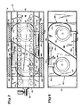
- Figure 2 is a cross-sectional view of the tunnel heater taken generally along lines 2-2 of Figure 1;
- Figure 3 is a fragmentary plan view taken generally along lines 3-3 of Figure 2;
- Figure 4 is a fragmentary cross-sectional view taken generally along lines 4-4 of Figure 2;
- Figure 5 is a· cross-sectional view taken generally along lines 5-5 of Figure 2;
- Figure 6 is a partial cross-sectional view taken generally along lines 6-6 of Figure 2;
- Figure 7 is a view similar to Figure 5 illustrating a further embodiment of the tunnel heater according to the invention; and
- Figure 8 is a view similar to Figure 6 further illustrating the further embodiment of the present invention.
- With reference now to the figures 1 to 6, the tunnel heater 10 is arranged to cook or otherwise heat food products by forced hot air convection, and includes a food product conveying arrangement so that food products to be heated may be automatically moved through the heater for cooking.
- Tunnel heater 10 includes a generally box-
like heater housing 12 supported uponlegs 14. Notably, heater 10 is designed so that one heater can be stacked upon another, which is particularly useful where space is somewhat limited.Heater housing 12 includes an outerupper wall 16 and an outerlower wall 18. The housing further includes spacedouter side walls outer end walls end walls like cavity 28 which extends the length of heater 10. -
Cavity 28 is adapted to receive food products to be heated, and to this end aconveyor 30 is provided which extends the length ofcavity 28 and beyond the ends thereof.Conveyor 30 includes an upper conveyor run 32 and a lower, return conveyor run 34 so that food products, such as 36, may be placed upon the upper conveyor run 32 and advanced throughtunnel cavity 28 of the heater. In this manner, food products are received through one end ofcavity 28, moved through the cavity onconveyor 30, and discharged from the conveyor at the other end ofcavity 28.Conveyor 30 is preferably provided with a variable speed control so that heating times of food products conveyed can be selectively varied. If desired,outer side wall 20 of theheater housing 12 may be provided with anelongated observation window 38 so that food products being conveyed through the heater may be readily inspected.Window 38 may be provided with sliding glass doors or the like to permit ready access totunnel cavity 28 intermediate the ends thereof. - In order to heat food products conveyed through
tunnel cavity 28 onconveyor 30, tunnel heater 10 provides for circulation of heated air within theheater housing 12 so that the heated air is directed against the upper and lower surfaces of food products conveyed through the heater. To provide circulation of air in this manner, a pair ofcentrifugal blowers 40 is provided for drawing air from withincavity 28, although a single blower or more than two blowers could of course be used. Eachblower 40 is provided with its ownelectric motor 42, with theblowers 40 arranged so that air drawn fromcavity 28 is drawn intoheating chamber 44 through a plurality of upper and lower intake holes 46 and 47 defined by a generally vertically disposedintake plate 48. As best shown in Figure 2,heating chamber 44 is further defined by upper andlower duct plates 50 which are positioned generally above and belowintake plate 48. - Air drawn into
heating chamber 44 is heated by a heater comprising aburner 52 which extends into the heating chamber. An electric heater can also be readily employed in the present tunnel heater.Burner 52 is preferably gas-fired, and is provided with a generally cylindrical flame tube 54 which extends intoheating chamber 44 and within which combustion by theburner 52 takes place.Burner 52 operates to selectively heat air drawn throughheating chamber 44 in response to thermostatically-regulated automatic controls, designated generally at 56. Notably, flame tube 54 minimizes direct impingement of heat energy from the burner onblowers 40 disposed immediately downstream of theheating chamber 44. Without flame tube 54,blowers 40 would otherwise tend to suck flames from burner 53 into the blower intakes. - Circulated air heated within
heating chamber 44 is drawn intocentrifugal blowers 40 throughrespective blower intakes 58 which define the low pressure or suction side of each blower. The heated, circulating air is blown radially from theblowers 40 inblower chambers 60 within which each ofblowers 40 is respectively disposed. - The configuration of the
blower chambers 60 is significant for providing aerodynamically efficient air flow as the circulating air is ducted from the blowers back totunnel cavity 28. Eachblower chamber 60 is defined by arespective end wall 62, and common top andbottom walls rear wall 68 which is spaced inwardly ofouter side wall 22 ofheater housing 12. In order to minimize heat transfer from the heated circulating air to theheater housing 12, suitablethermal insulation 69 is provided betweenouter side wall 22 andrear wall 68. - In the presently preferred embodiment, a dividing
wall 70 extends vertically fromtop wall 64 tobottom wall 66 and distinguishes the two blower chambers from each other. Significantly, a plurality ofarcuate plate arrangements 72 defines aerodynamically efficient, first and second pairs of generally scroll-shapedair flow passages 73, with each pair of passages in close association with and extending about a respective one ofblowers 40. Thepassages 73 of each pair are generally opposed to each other, with each extending approximately halfway about therespective blower 40. Significantly, thepassages 73 of each pair are arranged for opposite blower discharge to substantially equally distribute and duct air from therespective blower 40 to upper and lower sides oftunnel cavity 28 for flow against food products in the cavity. This arrangement for ducting circulating air flow within tunnel heater 10 has been found to promote highly efficient operation, which provides for fast and readily-controllable heating of food products conveyed throughtunnel cavity 28. - Air from within the
blower chambers 60 is circulated therefrom through upper and lower portions ofdischarge plate 74 to upper and lower air flow passages 77 and 79 (withblower intakes 58 disposed generally centrally of discharge plate 74).Discharge plate 74 defines a plurality ofdischarge openings 78, with each discharge opening 78 receiving flow from a respective one of scroll-shapedpassages 73. This preferred arrangement ofdischarge plate 74 cooperates with the scroll-shapedpassages 73 so that generally equal portions of the air circulated by eachblower 40 are respectively channeled through either one of the upper or lowerair flow passages 77 and 79 through which the air circulates. Air flow efficiency is enhanced by the provision ofarcuate guides 80 which are positioned generally adjacentrear wall 68, and are arranged to guide the flow of circulating air throughdischarge plate 74 transversely of the scroll-shapedpassages 73 which extend aboutblowers 40. - As best shown in Figure 2, the duct work of the present tunnel heater which defines upper and lower
air flow passages 77 and 79 provides each of these passages with a venturi-like configuration for directing heated air from theblowers 40 back to thetunnel cavity 28 for heating food products. Upper and lowerair flow passages 77 and 79 are respectively defined by upper andlower duct walls discharge plate 74 and converge toward the opposite side of theheater housing 12. The upper and lower venturi-like airflow passages 77 and 79 are further defined byduct plates 50 disposed above and belowintake plate 48 ofheating chamber 44. As will be observed, circulating air within each of theair flow passages 77 and 79 moves through an area of reduced cross-section (in the region of duct plates 50) and then into an area of expanded cross-section in the manner associated with venturi flow characteristics. Notably,arcuate guides 80 withinblower chambers 60 act to guide circulating air from the scroll-shapedpassages 73 aboutblowers 40 into the venturi-like air passages 77 and 79 downstream thereof. - In order to direct the flow of heated circulating air against food products conveyed through
tunnel cavity 28 onconveyor 30, the present apparatus includes upper and lowerforaminous plates lower plates tunnel cavity 28.Upper plate 86 andlower plate 88 are positioned inwardly of and between upper and lower intake holes 46 and 47 inintake plate 48. Intake holes 46 communicate withcavity 28 on the same side of theupper plate 86 that is associated with air passage 77. Similarly, intake holes 47 communicate withcavity 28 on the same side of thelower plate 88 that is associated withair passage 79. - Upper and
lower plates duct plates 50 toinner wall 90. Theinner wall 90 is spaced from theouter side wall 20 ofheater housing 12, with suitable thermal insulation provided therebetween for minimizing heat transfer from the heated circulating air to the heater housing. Eachplate channels - The configuration of
foraminous plates lower plate 88 which is of similar construction) includes at least oneperforated portion 97, which includes a plurality of relatively closely spaced air passage holes 98, and at least oneimperforate portion 99 adjacentperforated portion 97. Preferably, eachplate imperforate portions tunnel cavity 28. In this manner, the food products are conveyed through generally adjacent, non-discrete, alternating zones or areas of relatively high and relatively low convective heating. Passage of food products through high and low heating zones in this manner is desirable since moisture in the food products being heated is permitted to migrate toward the surfaces of the products during passage of the products through the zones of relatively low convective heating. More uniform heating of the products thereby results, providing cooked products have improved quality and appeal. This method of heating food products is particularly effective for heating or baking products having crusts or the like, resulting in products having the desired texture and doneness throughout. Depending upon the type of products to be heated, upper andlower plates - The relative spacing of food products from the
plates cavity 28 so that their surfaces are spaced between approximately one to three inches from theplates plates - In a presently preferred form, each
plate hole 98 ofperforated portions 97 is approximately 7,9 mm (5/16 of an inch) in diameter. Eachperforated portion 97 includes six rows ofholes 98 with adjacent holes of each row spaced on approximately 15,9 mm (5/8 inch) centers. Adjacent rows ofholes 98 are staggered with respect to each other by approximately 3,2 mm (1/8 inch). While various other perforated configurations for foraminous upper andlower plates holes 98 has been found to provide the desired high velocity, blanket-like flow of heated air against food products conveyed throughtunnel cavity 28. Further, the ducting of the heated circulating air through the venturi-like upper and lowerair flow passages 77 and 79 creates a relative increase in the pressure of the circulated air upstream of upper andlower plates tunnel cavity 28. - To further enhance the energy efficiency of the present tunnel heater apparatus, the internal duct work of the tunnel heater is supported within the
heater housing 12 so that conductive heat transfer from the heated circulating air to outer portions of the heater housing is minimized. To this end, supports 100 respectively extend between the upper and lowerouter walls heater housing 12 and top andbottom walls blower chambers 60 within the housing. Eachsupport 100 includes a plurality of spacedholes 102 so that eachsupport 100 includes a portion of reduced cross-section so that conductive heat transfer therethrough is minimized. Similarly, supports 104 are provided extending betweenend wall 90 and upper and lowerouter walls supports 104 each defining a plurality ofholes 106 for providing each support with a portion of reduced cross-section for minimizing conductive heat transfer therethrough. Significantly, the provision of supports such as 100 and 104, together with suitable thermal insulation, permits the outer surfaces ofheater housing 12 to remain relatively cool even though air circulated within the heater may be heated to temperatures on the order of several hundred degrees Fahrenheit. - In one current embodiment of the above- described tunnel heater apparatus, each of two
blowers 40 provided in the tunnel heater has a rated air flow capacity of approximately 35,4 m3/min (1250 cubic feet per minute) (CFM), with working air flow through each blower being approximately 21,2 m3/min (750 CFM). Upper and lowerforaminous plates lower plates tunnel cavity 28. Each plate 86- and 88 includes six spacedperforated portions 97 havingholes 98 spaced as described above. - Circulating air is heated by
burner 52 having a maximum rated output of approximately 105 500 kJ/h (100,000 BTU/hour), with the burner typically operating at a rate of 30,000-50,000 BTU/hour. Circulating air flow velocity within venturi-likeair flow passages 77 and 79 reaches approximately 31650-52750 kJ/h (3800-4000 feet/minute) through the areas of reduced cross-section, with air velocity decreasing to approximately 427-488 m/min (1400-1600 feet/minute) upstream offoraminous plates cavity 28 is on the order of approximately 549―610 m/min (1800-2000 feet/minute). This particular embodiment of the present tunnel heater has proven to provide highly acceptable results for commercial use. However, a wide variety of operating conditions can be readily provided in a heater apparatus made in accordance with the teachings herein. - With reference to Figures 7 and 8, a further embodiment for the circulating air duct work of the present heater is disclosed. This embodiment includes a different arrangement for the chambers within which
blowers 40 are positioned which acts to enhance aerodynamically efficient air flow in a manner similar to the arrangement ofblower chambers 60. - Circulated air heated within
heating chamber 44 is drawn intocentrifugal blowers 40 through therespective blower intakes 58, and is blown radially from the blowers inblower chambers 160 within which theblowers 40 are respectively disposed. Eachblower chamber 160 is defined by arespective end wall 162, and common top andbottom walls outer side wall 22 of heater housing 12). - A dividing
wall 170 extends angularly fromtop wall 164 tobottom wall 166 and distinguishes theblower chambers 160 from each other. Significantly, dividingwall 170, together with a plurality ofarcuate plate arrangements 172, defines aerodynamically efficient, generally scroll-shapedair flow passages 173 which are closely associated with and respectively extend about theblowers 40. Like the previously described arrangement ofblower chambers 60, this arrangement ofchambers 160 for ducting circulating air flow has been found to promote highly efficient operation. - Air from within the
blower chambers 160 is circulated therefrom through upper and lower portions of discharge plate 174 (positioned within heater 10 like discharge plate 74) to the upper and lowerair flow passages 77 and 79. Discharge plate 174 definesdischarge openings blowers 40 flows. Discharge plate 174 acts in cooperation withblower chambers 160 to baffle air flow from theblowers 40 for distribution to upper and lowerair flow passages 77 and 79. If desired, the configuration of discharge plate 174 can be provided so that air flow from eachblower 42 is evenly distributed betweenpassages 77 and 79. Alternatively, a predominant portion of the air flow from one of the blowers can be directed to one ofpassages 77 and 79, with a predominant air flow from the other blower directed to the other of thepassages 77 and 79. This latter flow distribution is achieved by sizing andpositioning discharge openings rear wall 168, and are arranged to guide the flow of circulating air through discharge plate 174 transversely of the scroll-shapedpassages 173 which respectively extend about eachblower 40. - Thus, a tunnel heater apparatus is disclosed which greatly facilitates efficient heating and preparation of food products. The present arrangement not only heats food products in a relatively rapid fashion by the use of forced air convection for cooking, but is also energy efficient, with aerodynamically correct air flow passages promoting smooth and efficient circulation of heated air for heating food products.
Claims (12)
Applications Claiming Priority (2)
| Application Number | Priority Date | Filing Date | Title |
|---|---|---|---|
| US379738 | 1982-05-19 | ||
| US06/379,738 US4471750A (en) | 1982-05-19 | 1982-05-19 | Tunnel heater |
Publications (3)
| Publication Number | Publication Date |
|---|---|
| EP0094816A2 EP0094816A2 (en) | 1983-11-23 |
| EP0094816A3 EP0094816A3 (en) | 1984-04-11 |
| EP0094816B1 true EP0094816B1 (en) | 1986-11-05 |
Family
ID=23498480
Family Applications (1)
| Application Number | Title | Priority Date | Filing Date |
|---|---|---|---|
| EP83302737A Expired EP0094816B1 (en) | 1982-05-19 | 1983-05-16 | Apparatus and method for heating food products |
Country Status (5)
| Country | Link |
|---|---|
| US (1) | US4471750A (en) |
| EP (1) | EP0094816B1 (en) |
| CA (1) | CA1193898A (en) |
| DE (1) | DE3367456D1 (en) |
| IE (1) | IE54190B1 (en) |
Families Citing this family (34)
| Publication number | Priority date | Publication date | Assignee | Title |
|---|---|---|---|---|
| US4576090A (en) * | 1982-05-19 | 1986-03-18 | Mastermatic, Inc. | Tunnel heater |
| DE3306972A1 (en) * | 1983-02-28 | 1984-10-04 | Buderus Ag, 6330 Wetzlar | DEVICE FOR HEAT TREATMENT OF FOOD AND FOOD |
| US4616562A (en) * | 1985-06-21 | 1986-10-14 | Kuechler Irvin R | Ventilation system for pizza ovens |
| WO1988000681A1 (en) * | 1985-07-10 | 1988-01-28 | Archer Aire Industries, Inc. | Air slot cooking grill |
| US4873107A (en) * | 1986-12-24 | 1989-10-10 | Archer Air Industries, Inc. | Air impingement tunnel oven apparatus |
| US4753215A (en) * | 1987-01-14 | 1988-06-28 | Lincoln Foodservice Products, Inc. | Burner for low profile inpingement oven |
| US4949629A (en) * | 1987-10-13 | 1990-08-21 | Heat And Control, Inc. | Cooking a food product in a process vapor at progressively varying rates |
| US4924763A (en) * | 1988-10-17 | 1990-05-15 | Pizza Hut | Compact pizza oven |
| US4919477A (en) * | 1988-10-17 | 1990-04-24 | Pizza Hut, Inc. | Compact pizza preparation and delivery vehicle |
| US4951645A (en) * | 1988-12-02 | 1990-08-28 | Welbilt Corporation | Stacked duel module commercial hot air impingement cooking oven |
| US4972824A (en) * | 1988-12-02 | 1990-11-27 | Welbilt Corporation | Commercial hot air impingement cooking apparatus |
| US5239917A (en) * | 1991-06-06 | 1993-08-31 | Genie Tech, Inc. | Oven |
| US5421316A (en) * | 1994-01-31 | 1995-06-06 | G. S. Blodgett Corporation | Conveyor oven with improved air flow |
| CA2191786A1 (en) * | 1996-11-29 | 1998-05-29 | Georges Moshonas | Impingement food apparatus |
| DE19730829A1 (en) | 1997-07-18 | 1999-01-28 | Riesselmann Gottfried | Device for heating food |
| US5845631A (en) * | 1997-08-21 | 1998-12-08 | Kerry Ingredients, Inc. | Heat exchanger for convection baking ovens |
| US6526961B1 (en) * | 2000-07-10 | 2003-03-04 | Lincoln Foodservice Products, Inc | Conveyor oven |
| AU2005311599B2 (en) * | 2004-12-03 | 2011-02-03 | Turbochef Technologies, Inc. | High speed convection oven |
| WO2006065807A2 (en) * | 2004-12-14 | 2006-06-22 | Enodis Corporation | Impingement/ convection/ microwave oven and method |
| US7624728B1 (en) * | 2004-12-22 | 2009-12-01 | David C Forbes | Impingement tunnel oven with reduced energy consumption and reduced maintenance |
| US7820216B1 (en) * | 2007-10-23 | 2010-10-26 | Alkar-Rapidpak-Mp Equipment, Inc. | Apparatus and methods for pasteurizing food product |
| US8350192B2 (en) * | 2008-07-18 | 2013-01-08 | Electrolux Home Products, Inc. | Dual fan convection performance divider |
| US9044024B2 (en) | 2011-01-14 | 2015-06-02 | Cleveland Range, Llc | Oven door |
| US8637792B2 (en) | 2011-05-18 | 2014-01-28 | Prince Castle, LLC | Conveyor oven with adjustable air vents |
| GB201205766D0 (en) * | 2012-03-30 | 2012-05-16 | Oxford Optronix Ltd | Controlled atmosphere workstation |
| US20140199446A1 (en) * | 2013-01-11 | 2014-07-17 | Star Manufacturing International, Inc. | Split-Belt Conveyor Toaster |
| US10337745B2 (en) | 2015-06-08 | 2019-07-02 | Alto-Shaam, Inc. | Convection oven |
| US9677774B2 (en) | 2015-06-08 | 2017-06-13 | Alto-Shaam, Inc. | Multi-zone oven with variable cavity sizes |
| US9879865B2 (en) | 2015-06-08 | 2018-01-30 | Alto-Shaam, Inc. | Cooking oven |
| US10088172B2 (en) | 2016-07-29 | 2018-10-02 | Alto-Shaam, Inc. | Oven using structured air |
| US10890336B2 (en) | 2015-06-08 | 2021-01-12 | Alto-Shaam, Inc. | Thermal management system for multizone oven |
| AU2017231095B2 (en) * | 2016-03-09 | 2022-12-08 | Dmp Enterprises Pty Ltd | Conveyor-type oven |
| IT201700117996A1 (en) * | 2017-10-18 | 2019-04-18 | Prismafood S R L | COOKING SYSTEM FOR FOOD AND ITS METHOD |
| CN215305176U (en) * | 2021-06-15 | 2021-12-28 | 江门市新会恒隆家居创新用品有限公司 | Toaster |
Family Cites Families (39)
| Publication number | Priority date | Publication date | Assignee | Title |
|---|---|---|---|---|
| US3065553A (en) * | 1962-11-27 | R olin | ||
| US1617609A (en) * | 1922-03-16 | 1927-02-15 | Gas Res Co | Apparatus for effecting heat transfer |
| US1717115A (en) * | 1928-05-19 | 1929-06-11 | Mccann Harry Paul | Ventilating system for ovens |
| US1847915A (en) * | 1930-03-08 | 1932-03-01 | Thermox Inc | Apparatus for drying paper and the like |
| US1860887A (en) * | 1930-08-19 | 1932-05-31 | Charles E Buysse | Furnace |
| US2330938A (en) * | 1941-11-14 | 1943-10-05 | Torrington Mfg Co | Multiple outlet blower assembly |
| US2504320A (en) * | 1945-02-26 | 1950-04-18 | Lindberg Eng Co | Method of and apparatus for forced convection heating |
| US2491687A (en) * | 1945-06-26 | 1949-12-20 | Nutt John Henry | Apparatus for baking dough products |
| US2674811A (en) * | 1950-11-17 | 1954-04-13 | Us Rubber Co | Drier for porous materials |
| US2908234A (en) * | 1954-06-12 | 1959-10-13 | T & T Vicars Ltd | Bakers' and the like ovens |
| US3104187A (en) * | 1958-04-15 | 1963-09-17 | Owens Illinois Glass Co | Method for cleaning corrugated partition strips |
| US3129072A (en) * | 1958-12-29 | 1964-04-14 | Midland Ross Corp | Heat transfer apparatus for continuously moving strip |
| US3015893A (en) * | 1960-03-14 | 1962-01-09 | Mccreary John | Fluid flow control device for tenter machines utilizing super-heated steam |
| US3074179A (en) * | 1960-08-26 | 1963-01-22 | Faustel Inc | Web dryer |
| US3173384A (en) * | 1961-06-07 | 1965-03-16 | Baker Perkins Inc | Baking oven |
| US3266559A (en) * | 1963-02-15 | 1966-08-16 | American Mach & Foundry | Method of drying foamed materials, e. g. foods |
| US3374106A (en) * | 1964-05-14 | 1968-03-19 | Proctor & Schwartz Inc | Material drying method and apparatus |
| US3514576A (en) * | 1968-06-24 | 1970-05-26 | Hirst Microwave Heating Ltd | Combined microwave and hot air oven |
| NL6908455A (en) * | 1968-07-20 | 1970-01-22 | ||
| GB1244257A (en) * | 1969-01-31 | 1971-08-25 | Gas Council | Improvements in or relating to forced convection ovens |
| US3561885A (en) * | 1969-08-11 | 1971-02-09 | Pyronics Inc | Blower housing |
| US3605717A (en) * | 1969-11-10 | 1971-09-20 | Crown X Inc | Convection oven |
| US3692968A (en) * | 1970-04-06 | 1972-09-19 | Sanyo Electric Co | Electronic oven |
| US3821454A (en) * | 1971-12-15 | 1974-06-28 | Leon Lobel | Method of ageing meat |
| US3747513A (en) * | 1972-03-03 | 1973-07-24 | K C Seelback Co Inc | Apparatus for processing foodstuffs |
| SE363229B (en) * | 1972-03-15 | 1974-01-14 | Electrolux Ab | |
| GB1426367A (en) * | 1972-06-15 | 1976-02-25 | Burger Eisenwerke Ag | Gas-heated oven for heating foodstuffs |
| DE7238931U (en) * | 1972-10-24 | 1973-03-29 | Licentia Gmbh | COOKING STOVE WITH CIRCULATION OF A HOT AIR FLOW THROUGH A FAN IN A WARM ROOM THAT CAN BE LOCKED FROM THE OUTSIDE |
| US3884213A (en) * | 1973-03-30 | 1975-05-20 | Donald P Smith | Cooking apparatus |
| US3908533A (en) * | 1973-04-04 | 1975-09-30 | Electrolux Ab | Apparatus for continuously cooking food in sequential oven section of an elongated oven |
| DE2400845A1 (en) * | 1974-01-09 | 1975-07-17 | Burger Eisenwerke Ag | DEVICE FOR HEAT TREATMENT OF FOOD AND FOOD |
| US4338911A (en) * | 1976-05-19 | 1982-07-13 | Smith Donald P | Cooking apparatus |
| US4154861A (en) * | 1976-05-19 | 1979-05-15 | Smith Donald P | Heat treatment of food products |
| US4109636A (en) * | 1976-12-22 | 1978-08-29 | British Gas Corporation | Forced convection ovens |
| DE2709068C3 (en) * | 1977-03-02 | 1985-12-05 | Debag Deutsche Backofenbau GmbH, 8000 München | oven |
| CH624460A5 (en) * | 1977-05-24 | 1981-07-31 | Gautschi Electro Fours Sa | |
| SE409164B (en) * | 1978-06-19 | 1979-08-06 | Tipe Revent Ab | BAKUGN |
| DE2908348A1 (en) * | 1979-03-03 | 1980-09-04 | Vits Maschinenbau Gmbh | FLOATING DRYER |
| DE2950946C2 (en) * | 1979-12-18 | 1984-08-09 | Bosch-Siemens Hausgeräte GmbH, 7000 Stuttgart | Oven with fan and grill element |
-
1982
- 1982-05-19 US US06/379,738 patent/US4471750A/en not_active Expired - Lifetime
-
1983
- 1983-05-10 IE IE1079/83A patent/IE54190B1/en not_active IP Right Cessation
- 1983-05-16 DE DE8383302737T patent/DE3367456D1/en not_active Expired
- 1983-05-16 EP EP83302737A patent/EP0094816B1/en not_active Expired
- 1983-05-17 CA CA000428350A patent/CA1193898A/en not_active Expired
Also Published As
| Publication number | Publication date |
|---|---|
| DE3367456D1 (en) | 1986-12-11 |
| IE54190B1 (en) | 1989-07-05 |
| CA1193898A (en) | 1985-09-24 |
| IE831079L (en) | 1983-11-19 |
| EP0094816A2 (en) | 1983-11-23 |
| EP0094816A3 (en) | 1984-04-11 |
| US4471750A (en) | 1984-09-18 |
Similar Documents
| Publication | Publication Date | Title |
|---|---|---|
| EP0094816B1 (en) | Apparatus and method for heating food products | |
| US4576090A (en) | Tunnel heater | |
| CA1110686A (en) | Circulating air oven for holding and cooking food | |
| CA2041872C (en) | Air delivery system and oven control circuitry cooling system for a low profile impingement oven | |
| US6943321B2 (en) | Convection oven with forced airflow circulation zones | |
| EP1797758B1 (en) | Continuous cooking oven system | |
| US5239917A (en) | Oven | |
| EP0086568B1 (en) | Thermal treatment of food products | |
| US5958274A (en) | Jet impingement batch oven | |
| US6817283B2 (en) | High speed cooking device and method | |
| EP2074369B1 (en) | Impinging air ovens having high mass flow orifices | |
| US7205507B2 (en) | Food cooking and heating apparatus | |
| US5172682A (en) | Commercial hot air impingement cooking apparatus | |
| IL44255A (en) | Cooking oven with forced air circulation | |
| JPH0738775B2 (en) | Cooking food products in process steam at progressively variable rates | |
| US5165889A (en) | Gas convection oven with heat exchanger and baffles | |
| EP0185059A1 (en) | Continuous feed oven | |
| EP0370021A1 (en) | Method and apparatus for pulse heating and cooking food products | |
| US4534987A (en) | Method of convection cooking of food | |
| EP1442660A1 (en) | Oven for the continuous cooking of food products | |
| EP1744633A1 (en) | System to convey air for convection or static ovens through cylinders and/or interstice and system of vertical opposed ventilation | |
| JPH09126458A (en) | Convection oven | |
| JP3823062B2 (en) | Cooker | |
| JPH09229366A (en) | Hot air circulation type gas oven, and hot air circulation method for hot air circulation type gas oven | |
| JPH05164326A (en) | Forced convection oven for cooking or heating food |
Legal Events
| Date | Code | Title | Description |
|---|---|---|---|
| PUAI | Public reference made under article 153(3) epc to a published international application that has entered the european phase |
Free format text: ORIGINAL CODE: 0009012 |
|
| AK | Designated contracting states |
Designated state(s): BE CH DE FR GB LI NL |
|
| PUAL | Search report despatched |
Free format text: ORIGINAL CODE: 0009013 |
|
| AK | Designated contracting states |
Designated state(s): BE CH DE FR GB LI NL |
|
| 17P | Request for examination filed |
Effective date: 19841010 |
|
| GRAA | (expected) grant |
Free format text: ORIGINAL CODE: 0009210 |
|
| AK | Designated contracting states |
Kind code of ref document: B1 Designated state(s): BE CH DE FR GB LI NL |
|
| REF | Corresponds to: |
Ref document number: 3367456 Country of ref document: DE Date of ref document: 19861211 |
|
| ET | Fr: translation filed | ||
| PGFP | Annual fee paid to national office [announced via postgrant information from national office to epo] |
Ref country code: NL Payment date: 19870531 Year of fee payment: 5 |
|
| PLBE | No opposition filed within time limit |
Free format text: ORIGINAL CODE: 0009261 |
|
| STAA | Information on the status of an ep patent application or granted ep patent |
Free format text: STATUS: NO OPPOSITION FILED WITHIN TIME LIMIT |
|
| 26N | No opposition filed | ||
| PG25 | Lapsed in a contracting state [announced via postgrant information from national office to epo] |
Ref country code: GB Effective date: 19890516 |
|
| PG25 | Lapsed in a contracting state [announced via postgrant information from national office to epo] |
Ref country code: LI Effective date: 19890531 Ref country code: CH Effective date: 19890531 Ref country code: BE Effective date: 19890531 |
|
| PG25 | Lapsed in a contracting state [announced via postgrant information from national office to epo] |
Ref country code: NL Effective date: 19891201 |
|
| GBPC | Gb: european patent ceased through non-payment of renewal fee | ||
| NLV4 | Nl: lapsed or anulled due to non-payment of the annual fee | ||
| PG25 | Lapsed in a contracting state [announced via postgrant information from national office to epo] |
Ref country code: FR Free format text: LAPSE BECAUSE OF NON-PAYMENT OF DUE FEES Effective date: 19900131 |
|
| REG | Reference to a national code |
Ref country code: CH Ref legal event code: PL |
|
| PG25 | Lapsed in a contracting state [announced via postgrant information from national office to epo] |
Ref country code: DE Effective date: 19900201 |
|
| REG | Reference to a national code |
Ref country code: FR Ref legal event code: ST |