EP2073883B1 - Extravascular system in-line venting - Google Patents
Extravascular system in-line venting Download PDFInfo
- Publication number
- EP2073883B1 EP2073883B1 EP07843857.9A EP07843857A EP2073883B1 EP 2073883 B1 EP2073883 B1 EP 2073883B1 EP 07843857 A EP07843857 A EP 07843857A EP 2073883 B1 EP2073883 B1 EP 2073883B1
- Authority
- EP
- European Patent Office
- Prior art keywords
- vent
- gas
- medical device
- fluid path
- cannula
- Prior art date
- Legal status (The legal status is an assumption and is not a legal conclusion. Google has not performed a legal analysis and makes no representation as to the accuracy of the status listed.)
- Active
Links
- 238000013022 venting Methods 0.000 title claims description 41
- 239000012530 fluid Substances 0.000 claims description 102
- 239000000463 material Substances 0.000 claims description 60
- 239000007788 liquid Substances 0.000 claims description 43
- 230000002792 vascular Effects 0.000 claims description 36
- 238000004891 communication Methods 0.000 claims description 27
- 238000007789 sealing Methods 0.000 claims description 23
- 238000013008 moisture curing Methods 0.000 claims description 8
- 229920001971 elastomer Polymers 0.000 claims description 5
- 239000000806 elastomer Substances 0.000 claims description 5
- 239000012528 membrane Substances 0.000 claims description 5
- 230000017531 blood circulation Effects 0.000 claims description 2
- 239000008280 blood Substances 0.000 description 28
- 210000004369 blood Anatomy 0.000 description 28
- 238000000034 method Methods 0.000 description 23
- 238000001802 infusion Methods 0.000 description 10
- 210000005166 vasculature Anatomy 0.000 description 9
- 238000002560 therapeutic procedure Methods 0.000 description 6
- 230000008901 benefit Effects 0.000 description 5
- 238000003780 insertion Methods 0.000 description 4
- 230000037431 insertion Effects 0.000 description 4
- 230000002093 peripheral effect Effects 0.000 description 4
- 230000007774 longterm Effects 0.000 description 3
- 239000011148 porous material Substances 0.000 description 3
- 230000036772 blood pressure Effects 0.000 description 2
- 230000006835 compression Effects 0.000 description 2
- 238000007906 compression Methods 0.000 description 2
- 238000011109 contamination Methods 0.000 description 2
- 238000001723 curing Methods 0.000 description 2
- 230000000977 initiatory effect Effects 0.000 description 2
- 238000001990 intravenous administration Methods 0.000 description 2
- 230000007246 mechanism Effects 0.000 description 2
- 229920002635 polyurethane Polymers 0.000 description 2
- 239000004814 polyurethane Substances 0.000 description 2
- 230000004044 response Effects 0.000 description 2
- 238000009738 saturating Methods 0.000 description 2
- XLYOFNOQVPJJNP-UHFFFAOYSA-N water Substances O XLYOFNOQVPJJNP-UHFFFAOYSA-N 0.000 description 2
- 206010002091 Anaesthesia Diseases 0.000 description 1
- FAPWRFPIFSIZLT-UHFFFAOYSA-M Sodium chloride Chemical compound [Na+].[Cl-] FAPWRFPIFSIZLT-UHFFFAOYSA-M 0.000 description 1
- 230000037005 anaesthesia Effects 0.000 description 1
- 230000036592 analgesia Effects 0.000 description 1
- 238000004873 anchoring Methods 0.000 description 1
- 230000000845 anti-microbial effect Effects 0.000 description 1
- 239000010836 blood and blood product Substances 0.000 description 1
- 229940125691 blood product Drugs 0.000 description 1
- 210000001124 body fluid Anatomy 0.000 description 1
- 239000010839 body fluid Substances 0.000 description 1
- 238000000576 coating method Methods 0.000 description 1
- 238000013461 design Methods 0.000 description 1
- 239000003814 drug Substances 0.000 description 1
- 239000007789 gas Substances 0.000 description 1
- 230000012010 growth Effects 0.000 description 1
- 230000036541 health Effects 0.000 description 1
- 208000015181 infectious disease Diseases 0.000 description 1
- 238000002347 injection Methods 0.000 description 1
- 239000007924 injection Substances 0.000 description 1
- 235000016709 nutrition Nutrition 0.000 description 1
- 230000001681 protective effect Effects 0.000 description 1
- 238000010992 reflux Methods 0.000 description 1
- 230000033764 rhythmic process Effects 0.000 description 1
- 229920006395 saturated elastomer Polymers 0.000 description 1
- 239000011780 sodium chloride Substances 0.000 description 1
- 238000012546 transfer Methods 0.000 description 1
- 238000011282 treatment Methods 0.000 description 1
- 238000011144 upstream manufacturing Methods 0.000 description 1
- 210000003462 vein Anatomy 0.000 description 1
Images


Classifications
-
- A—HUMAN NECESSITIES
- A61—MEDICAL OR VETERINARY SCIENCE; HYGIENE
- A61M—DEVICES FOR INTRODUCING MEDIA INTO, OR ONTO, THE BODY; DEVICES FOR TRANSDUCING BODY MEDIA OR FOR TAKING MEDIA FROM THE BODY; DEVICES FOR PRODUCING OR ENDING SLEEP OR STUPOR
- A61M25/00—Catheters; Hollow probes
- A61M25/01—Introducing, guiding, advancing, emplacing or holding catheters
- A61M25/06—Body-piercing guide needles or the like
- A61M25/0606—"Over-the-needle" catheter assemblies, e.g. I.V. catheters
-
- A—HUMAN NECESSITIES
- A61—MEDICAL OR VETERINARY SCIENCE; HYGIENE
- A61M—DEVICES FOR INTRODUCING MEDIA INTO, OR ONTO, THE BODY; DEVICES FOR TRANSDUCING BODY MEDIA OR FOR TAKING MEDIA FROM THE BODY; DEVICES FOR PRODUCING OR ENDING SLEEP OR STUPOR
- A61M39/00—Tubes, tube connectors, tube couplings, valves, access sites or the like, specially adapted for medical use
- A61M39/22—Valves or arrangement of valves
- A61M39/24—Check- or non-return valves
Definitions
- Infusion therapy is one of the most common health care procedures. Hospitalized, home care, and other patients receive fluids, pharmaceuticals, and blood products via a vascular access device inserted into the vascular system. Infusion therapy may be used to treat an infection, provide anesthesia or analgesia, provide nutritional support, treat cancerous growths, maintain blood pressure and heart rhythm, or many other clinically significant uses.
- vascular access device may access a patient's peripheral or central vasculature.
- the vascular access device may be indwelling for short term (days), moderate term (weeks), or long term (months to years).
- the vascular access device may be used for continuous infusion therapy or for intermittent therapy.
- a common vascular access device is a catheter that is inserted into a patient's vein.
- the catheter length may vary from a few centimeters for peripheral access to many centimeters for central access.
- the catheter may be inserted transcutaneously or may be surgically implanted beneath the patient's skin.
- the catheter, or any other vascular access device attached thereto may have a single lumen or multiple lumens for infusion of many fluids simultaneously.
- One or more vascular or other devices used to access the vasculature of a patient are collectively referred to herein as an extravascular system.
- an extravascular system including a catheter is the BD NEXIVATM Closed IV (intravenous) Catheter System, by Becton, Dickinson and Company.
- This system includes an over-the-needle, peripheral intravascular catheter made from polyurethane, another catheter used as an integrated extension tubing with a Y adapter and slide clamp, a vent plug, a Luer access device or port, and a passive needle-shielding mechanism.
- the design of the BD NEXIVATM IV catheter can be described as a closed system since it protects clinicians or operators from blood exposure during the catheter insertion procedure. Since the needle is withdrawn through a septum that seals, after the needle has been removed and both ports of the Y adapter are closed, blood is contained within the NEXIVATM device during catheter insertion. The pressure exerted on the needle as it passes through the septum wipes blood from the needle, further reducing potential blood exposure. The slide clamp on the integrated extension tubing is provided to eliminate blood exposure when the vent plug is replaced with another vascular access device such as an infusion set connection or a Luer access device or port.
- another vascular access device such as an infusion set connection or a Luer access device or port.
- a device operator will insert the needle into the vasculature of a patient and wait for flashback of blood to travel into the device to confirm that the needle is properly located within the vasculature of the patient.
- the blood travels into and along the catheter of the device because a vent plug permits air to escape the device as blood enters the device.
- the operator clamps the catheter to halt the progression of blood through the catheter, removes the vent plug, replaces the vent plug with another vascular access device such as an infusion set connection or a Luer access port, unclamps the catheter, flushes the blood from the catheter back into the vasculature of the patient, and re-clamps the catheter.
- another vascular access device such as an infusion set connection or a Luer access port
- the procedure may include an unnecessary number of steps and amount of time to simply insert and prepare an extravascular system for use within the vasculature of a patient. Further, by removing the vent plug, the fluid path of the system is temporarily exposed to potential contamination from the external environment of the extravascular system.
- WO 97/45151 describes a catheter system comprising an adapter sealed with a plug, whereas the plug comprises a gas vent.
- a valve is arranged whereby the valve body is pushed in a closed position due to the blood pressure sealing the fluid path.
- US 4,106,491 describes a catheter system comprising a catheter assembly connected to an adapter by a fluid path.
- the adapter is closed by a plug, whereas gas contained within the fluid path can escape through a gas-permeable and fluid-impermeable space between plug and adapter.
- the present invention has been developed in response to problems and needs in the art that have not yet been fully resolved by currently available extravascular systems, devices, and methods. Thus, these systems, devices, and methods are developed to provide more efficient extravascular venting systems and methods.
- a medical device may include a closed extravascular system having a fluid path and a gas vent in communication with the fluid path.
- the closed extravascular system may remain closed after gas vents from the fluid path through the gas vent.
- the gas vent may include a venting material and a user-activated rotation valve, a user-activated seal with a pull tab, at least two layers of fluid seal material separated by a layer of gas, a removable filter plug and a re-seal elastomer, and/or a cannula and a cartridge seal.
- the gas vent may include a cannula with a first end and a second end, a venting material secured to the first end of the cannula, a push shaft with a first end and a second end, and a septum secured to the second end of the push shaft and in movable contact with the second end of the cannula.
- the gas vent may include a narrow vent hole and a floatable structure and/or a heavy structure in the fluid path and in communication with the narrow vent hole.
- the gas vent may include a spring-loaded sealing member, a sealing member that expands when the sealing member comes into contact with liquid, a check valve, a moisture-cure material, and/or a porous membrane.
- the vent may be in direct communication with the fluid path.
- the gas vent may include an expandable vent material, a cannula with a first end and a second end, and a septum in communication with the second end of the cannula.
- the first end of a cannula may be anchored within the expandable vent material.
- the vent material may be capable of expanding and drawing the second end of the cannula through the septum when the vent material is exposed to liquid.
- a method of venting a medical device may include providing a closed extravascular system having a fluid path, providing a gas vent in communication with the fluid path, venting gas from the extravascular system through the gas vent, and maintaining a closed extravascular system during and after venting.
- the method may also include any of the following steps: closing the vent upon user-activation of the vent, saturating a first layer of venting material with liquid, removing the gas vent after venting, closing the vent with a floatable structure, closing the vent with a heavy structure, closing the vent with a spring-loaded sealing member, and/or closing the vent with an expandable sealing member.
- the step of providing a gas vent in communication with the fluid path may include providing the gas vent in direct communication with the fluid path.
- the method may further include curing a material to form a seal.
- the gas vent may include an expandable vent material, a cannula with a first end and a second end, and a septum in communication with the second end of the cannula. This method may further include anchoring the first end of a cannula within the expandable vent material, expanding the vent material, and drawing the second end of the cannula through the septum as the vent material expands.
- a medical device may include a means for providing access to the vascular system of a patient and a means for venting the means for providing access to the vascular system of a patient.
- the means for providing access to the vascular system of a patient may include a fluid path.
- the means for venting the means for providing access to the vascular system of a patient may communicate with the fluid path.
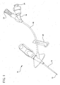
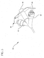
- an extravascular system 10 such as the BD NEXIVA(TM) Closed IV (intravenous) Catheter System, by Becton, Dickinson and Company, is used to communicate fluid with the vascular system of a patient.
- An example of the system 10, as shown in Figure 1 includes multiple vascular access devices such as an intravascular needle 12; an over-the-needle, peripheral intravascular catheter 14 made from polyurethane; an integrated extension tubing 16 (also referred to herein as a catheter) with a Y adapter 18 and slide clamp 20; a vent plug 22; a Luer access device or port 24; and a passive needle-shielding mechanism.
- Any adapter used to connect two or more vascular access devices may be used in place of the Y adapter 18.
- the system 10 is initially a closed system since it protects clinicians or operators from blood exposure during the catheter 14 insertion procedure. Since the needle 12 is withdrawn through a septum that seals after the needle 12 has been removed and both ports of the Y adapter 18 are closed, blood is contained within the system 10 during catheter 14 insertion. The pressure exerted on the needle 12 as it passes through the septum wipes blood from the needle 12, further reducing potential blood exposure.
- the slide clamp 20 on the integrated extension tubing 16 is provided to eliminate blood exposure when the vent plug 22 is replaced with another vascular access device such as an infusion set connection or another Luer access device or port 24.
- a current procedure of initiating the use of the extravascular system 10 is as follows.
- a device operator will insert the needle 12 into the vasculature of a patient and wait for flashback of blood to travel into the system 10 to confirm that the needle 12 is properly located within the vasculature of the patient.
- the blood travels into and along the catheter 14 and extension tubing 16 because a vent plug 22 permits air to escape the system 10 as blood enters the system 10.
- the operator clamps the catheter 16 to halt the progression of blood through the catheters 14 and 16, removes the vent plug 22 (temporarily opening the otherwise closed extravascular system 10), replaces the vent plug 22 with another vascular access device such as an infusion set connection or a Luer access device similar or identical to Luer access device or port 24 (re-closing the extravascular system 10), unclamps the catheter 16, flushes the blood from the catheters 14 and 16 back into the vasculature of the patient, and re-clamps the catheter 16.
- another vascular access device such as an infusion set connection or a Luer access device similar or identical to Luer access device or port 24 (re-closing the extravascular system 10)
- vents and venting procedures are desired and will be discussed with reference to the figures following Figure 1 . Specifically, vents and venting procedures that, among other advantages, do not require opening of an otherwise closed extravascular system may be desired.
- a vent may be placed.near the terminus of a fluid path of an extravascular system in order to ensure that all gas within the entire fluid path of the extravascular system is vented from the extravascular system.
- Vents may also be placed in areas of stagnant flow within the extravascular system in order to remove all gas and/or stagnant fluid from the venting area.
- One or more vents, and one or more of the elements or features thereof, may be combined in any combination and applied to an extravascular system. Such combination may occur in order to eliminate stagnant gas and liquid, minimize and/or maximize blood reflux, ensure full venting of gas from the extravascular system, and achieve other desired benefits.
- an extravascular system 10 includes a fluid path 28 within the interior of the extravascular system 10.
- the fluid path 28 is in communication with a vent 30, and the vent 30 is capable of venting gas from the fluid path 28 of the system 10.
- the extravascular system 10 remains closed both during and after venting of gas through the vent 30.
- an operator of the extravascular system 10 may vent the system 10 without ever removing the vent 30 from the system 10 in a manner that exposes the operator to the fluid path 28 of the system 10.
- the vent 30 may include multiple embodiments.
- the vent 30 includes a venting material 32 and a user-activated rotation valve 34.
- An operator or user may rotate the rotation valve 34 in order to close exposure to the vent plug or venting material 32. Airflow or gas flow will travel from the fluid path 28, through the venting material 32, and out the user-activated rotation valve 34 when the valve 34 is open. When the valve 34 is closed, no air or other fluid will travel through the vent 30.
- the vent 30 includes a user-activated seal 36 with a pull tab 38. Air or other gas will travel around the edges 40 of the user-activated seal 36 until a user pulls upward on the pull tab 38, causing a bottom disc 42 of the seal 36 to come into contact with an inner surface of the body of the extravascular system 10. When the disc 42 comes into contact with the surface of the extravascular system 10, the user-activated seal 36 will close the airflow channels adjacent the seal 36, preventing any further gas or other fluid from escaping the fluid path through the vent 30 into the external environment in which the system 10 is placed.
- the gas vent 30 includes at least two layers of fluid seal or other venting material separated by a layer of gas 44.
- a first layer of fluid seal material 46 is exposed to the inner surface of the system 10 that is in contact with the fluid path 28.
- a second layer of fluid seal material 48 is separated from the first seal 46 by the layer of gas 44 and is exposed to the external environment in which the extravascular system 10 is placed.
- an operator will allow the system 10 to vent through the vent 30, causing air to escape through both layers 46 and 48 into the external environment. After all or a substantial portion of gas has escaped the fluid path 28, blood or other liquid will come into contact with the first layer 46.
- the liquid will seep or weep through the first layer 46, saturating the first layer 46 of venting material. Because the second layer 48 is separated from the first layer 46 by a layer of gas 44, the liquid that has saturated the first layer 46 will not travel to the second layer 48. Since liquid will not travel to the second layer 48, an operator will never be exposed to blood from a patient during the venting procedure for the extravascular system 10.
- an extravascular system 10 includes a fluid path 28 in communication with a vent 30.
- the vent 30 includes a removable filter plug 50 and a re-seal elastomer 52.
- the vent 30 is placed at or near vascular access devices on the system 10 capable of providing fluid access to the system 10.
- the vent 30 may be placed at or near the terminus of the system 10 in order to allow fluid, including gas, blood, saline, and water, to fill the internal chamber of the fluid path directly adjacent any vascular access devices of the system 10. Providing this location of the vent 30 on the system 10 will provide less gas and other stagnant fluid entrapment at this location.
- the vent 30 may be placed on an extravascular system with a Y or other port.
- the removable filter plug 50 may be removed from the system 10 after the system 10 is fully vented of gas and has been self-primed by allowing liquid to travel up to the vent 30 and neighboring vascular access devices. After the removable filter plug 50 is removed from the system 10 the re-seal elastomer 52 will seal the system 10, preventing any further unwanted fluid from exiting the fluid path 28 into the external environment in which the system 10 is placed.
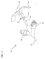
- an extravascular system 10 includes a fluid path 28 in communication with a vent 30.
- the vent 30 includes a cannula 54 and a cartridge seal 56.
- the cannula 54 provides a gas permeable vent through which gas may travel from the fluid path 28, through the cannula 54, across a venting material 58, and into the external environment in which the system 10 is placed.
- the cartridge seal 56 will seal the lumen in which the cannula 54 resided, preventing any further escape of gas and other fluid from the fluid path 28 into the external environment.
- the vent 30 may also include additional protective structure 60, which may or may not include antimicrobial coatings or other treatments on its surface, to protect the surfaces of vascular access devices 62 at our neighboring event.
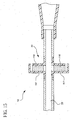
- FIG. 5 a cross section view of the extravascular system 10 of Figure 4 is shown.
- an extravascular system 10 includes a fluid path 28 in communication with a vent 30.
- the gas vent 30 includes a cannula 64 with a first end 66 and a second end, a venting material secured to the first end 66 of the cannula 64, a push shaft 72 with a first end 74 and a second end 76, and a septum 78 secured to the second end 76 of the push shaft 72 and in movable contact with the second end of the cannula 64.
- the septum 78 is in contact with the outer surface of the cannula 64 near the second end.
- the second end of the cannula 64 is exposed to the fluid path 28 of the system 10.
- gas will flow from the fluid path 28 into the second end of the cannula 64, through the first end 66 and the venting material, out a hole 80 in the first end 74 of the push shaft 72, and into the external environment in which the system 10 is placed.
- an operator may close the vent 30 by pushing the first end 74 of the push shaft 72 in a direction 82.
- the second end 76 of the push shaft 72 will force the septum 78 beyond the second end of the cannula 64.
- the septum 78 advances beyond the second end, the septum will be compressed by tapered walls 84 located on the interior surface of the extravascular system 10.
- the septum 78 Under compression of the tapered walls 84, the septum 78 will close the lumen that existed within the septum 78 when the second end penetrated the septum 78. As the septum lumen 78 closes, the vent 30 will be sealed from further gas or other fluid escaping the system 10 into the external environment.
- an extravascular system 10 includes a vent 30 having a narrow vent hole 86 and a floatable structure 88.
- the floatable structure 88 resides within the fluid path 28 of the system 10 and is in communication with the narrow vent hole 86.
- the floatable structure 88 is preferably not permeable to gas or other fluid.
- the floatable structure 88 is small enough to permit air or other gas to flow past the floatable structure 88, through the remainder of the fluid path 28, through the narrow vent hole 86, and into the external environment in which the system 10 is placed.
- the floatable structure 88 is capable of sealing the narrow vent hole 86 when in contact therewith.
- the floatable structure 88 may be formed of a material that expands when it comes into contact with liquid.
- the vent 30 of Figure 7 is shown with liquid in the fluid path 28.
- the floatable structure 88 With liquid placed in the fluid path 28, the floatable structure 88 has been forced upward as a result of its buoyancy on top of the liquid into the narrow vent hole 86, causing the narrow vent hole 86 to become sealed to any further flow of gas or other liquid.
- the material of the floatable structure 88 may expand as a result of its contact with liquid, causing the floatable structure 88 to fill and seal both the narrow vent hole 86 and the neighboring upper portion of the fluid path 28, in order to provide a long term seal against any future flow of gas or other fluid.
- an extravascular system 10 includes a fluid path 28 and a vent 30 in communication with the fluid path 28.
- the vent 30 may include at least one narrow vent hole 86 and one or more sealing structures, such as a floatable structure 88 and/or a heavy structure 90.
- the heavy structure 90 is capable of sinking in the presence of a liquid. Both the floatable structure 88 and the heavy structure 90 are placed within the fluid path 28 and are in sealing communication with the at least one narrow vent hole 86.
- the floatable and heavy structures 88 and 90 permit gas to travel around the structures 88 and 90 and through the at least one narrow vent hole 86 to the external environment. However, after liquid enters the fluid path 28, the liquid will cause the floatable structure 88 to rise towards an upper narrow vent hole 86 and will simultaneously cause the heavy structure 90 to sink towards a lower narrow vent hole 86. In this manner, either an upper or a lower vent hole 86 may be sealed by a sealing structure in response to the presence of a liquid within the fluid path 28.
- the embodiment described with reference to Figure 9 may include an expandable material used as either of these structures 88 and 90 in order to provide a long term or more effective seal of the fluid path 28 and/or the at least one narrow vent hole 86.
- an extravascular system 10 includes a fluid path 28 in communication with a vent 30.
- the vent 30 includes a spring-loaded sealing member 92 secured to the walls of the system 10 adjacent a vent hole 94 by means of a light spring 96.
- the light spring 96 requires very little force in order to become compressed.
- the spring-loaded sealing member 92 will allow gas to travel around the sealing member and through the vent hole 94, escaping to the external environment, while the light spring 96 is uncompressed.
- any expandable material capable of expanding upon coming into contact with a liquid may be employed as a vent 30 structure with a spring 96 in order to provide a vent capable of sealing upon liquid contact.
- any portion of the expandable material may be transferred into the lumen of the vent hole 94 as the material expands to seal off the vent hole 94.
- an extravascular system 10 includes a fluid path 28 in communication with a vent 30.
- the vent 30 includes a check valve 98.
- the check valve 98 may be a ball check or a plug check capable of sealing a gas path in communication with the fluid path 28.
- the vent 30 may be placed in proximity with other vascular access devices, such as Luer access devices, on a Y-shaped adapter of an extravascular system 10.
- the ball or plug check valve 98 is located in a position between two neighboring vascular access devices 100 to allow gas to escape the system 10 during venting. When liquid hits the ball or plug valve 98, the ball or plug moves into a neck 102, sealing off the vent 30 from any further gas or other fluid transfer between the fluid path 28 and the external environment.
- Injection of a liquid from either of the neighboring vascular access devices 100 would also press or force the ball or plug of the check valve 98 further into the neck 102 in order to seal the vent 30.
- the surface of the ball or plug of the check valve 98 may be such that after entry into the neck 102, the ball or plug is reluctant to exit the neck 102 and re-enter the fluid path 28.
- the ball or plug of the check valve 98 may include or be formed of any expandable material capable of expanding in the presence of a liquid. Thus the ball or plug could expand, after being forced by a liquid into the neck 102, causing the check valve 98 to fully and permanently seal the vent 30.
- the unique location of the vent 30 between the two neighboring vascular access devices 100 on a Y-shaped connector of the extravascular system 10 may minimize air, gas or other stagnant fluid volume within the Y-shaped adapter 104.
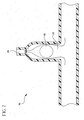
- a T-shaped adapter may employ the vent 30 between two neighboring vascular access devices 100.
- the embodiments described with reference to Figure 12 may advantageously provide a vent that is in direct communication with the active fluid path 28 of the system 10.
- no unnecessary volume is added to the vent in order to extend the vent away from the fluid path shared by neighboring vascular access devices 100.
- the vent 30 is located directly within the fluid path 28 between the downstream fluid path of the system 10 and the upstream fluid path of each particular neighboring vascular access device 100. This location prevents any dead gas or fluid volume within the fluid path 28 adjacent the vent 30.
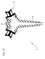
- an extravascular system 10 includes a fluid path 28 and a vent 30 in communication with the fluid path 28.
- the vent 30 includes a moisture-cure material 108 that is permeable to gas in the absence of a liquid.
- the vent 30 of Figure 13 is shown after liquid has entered into the fluid path 28 of the system 10.
- the liquid such as water or blood
- the liquid has caused the moisture-cure material 108 to become cured.
- the moisture-cure material 108 is no longer permeable to any fluid, including gas and liquid.
- the moisture-cure material 108 of the vent 30 described with reference to Figures 13 and 14 provides a vent capable of venting gas from the system 10 without permitting the escape of liquid after the liquid has come into contact with the material 108.
- an extravascular system 10 includes a fluid path 28 in communication with a vent 30.
- the vent 30 includes a porous membrane 110 secured by a housing 112 within the body of the system 10.
- the membrane 110 is gas, but not liquid, permeable.
- the vent 30 permits gas to escape from the fluid path 28 until the fluid path 28 includes only liquid.
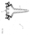
- an extravascular system 10 includes a fluid path 28 in communication with a vent 30.
- the vent 30 includes an expandable vent material 114 that is hydrophilic.
- the vent 30 also includes a cannula 116 with a first end 118 and a second end 120.
- the cannula may include multiple pores 122 along its length and in communication with the expanding material 114.
- the vent 30 also includes a septum 124 in communication with the second end 120 of the cannula 116.
- the first end 118 of the cannula 116 is anchored within the expandable vent material 114.
- the expandable vent material 114 is capable of expanding and drawing the second end 120 of the cannula 116 through the septum 124 when the vent material 114 is exposed to liquid from the fluid path 28.
- gas will travel from the fluid path 28 through the second end 120 of the cannula 116, through the pores 122 and first end 118 of the cannula 116, through the expanding material 114, through vent holes 126, and into the external environment in which the system 10 is placed.
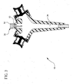
- liquid from the fluid path 28 will travel through the second end 120 of the cannula 116, through the pores 122 and end 118 of the cannula 116, and into the venting material 114.
- the venting material 114 will expand, causing the venting material to travel in a direction 128 within a wedged body 130 of the vent 30.
- the expanding material 114 will draw the anchored first end 118 of the cannula 116 in the direction 128. Since the septum 124 is secured to the body of the system 10, as the cannula 116 travels in a direction 128, the second end 120 of the cannula 116 will exit the septum 124. After the cannula 116 has fully exited the septum 124, the septum 124 will self-seal under compression, causing the lumen that previously existed in the septum 124 as a result of the second end 120 of the cannula 116, preventing any further gas or other fluid from traveling through the septum 124. Since the septum 124 is sealed to further gas and other fluid travel, no further fluid will be permitted to escape into the external environment.
Landscapes
- Health & Medical Sciences (AREA)
- Life Sciences & Earth Sciences (AREA)
- Heart & Thoracic Surgery (AREA)
- Biomedical Technology (AREA)
- Engineering & Computer Science (AREA)
- Anesthesiology (AREA)
- Pulmonology (AREA)
- Hematology (AREA)
- Animal Behavior & Ethology (AREA)
- General Health & Medical Sciences (AREA)
- Public Health (AREA)
- Veterinary Medicine (AREA)
- Biophysics (AREA)
- Infusion, Injection, And Reservoir Apparatuses (AREA)
- External Artificial Organs (AREA)
Applications Claiming Priority (3)
| Application Number | Priority Date | Filing Date | Title |
|---|---|---|---|
| US82835606P | 2006-10-05 | 2006-10-05 | |
| US11/864,527 US8062262B2 (en) | 2006-10-05 | 2007-09-28 | Extravascular system in-line venting |
| PCT/US2007/080468 WO2008043034A2 (en) | 2006-10-05 | 2007-10-04 | Extravascular system in-line venting |
Publications (3)
| Publication Number | Publication Date |
|---|---|
| EP2073883A2 EP2073883A2 (en) | 2009-07-01 |
| EP2073883A4 EP2073883A4 (en) | 2012-11-14 |
| EP2073883B1 true EP2073883B1 (en) | 2015-05-27 |
Family
ID=39269227
Family Applications (1)
| Application Number | Title | Priority Date | Filing Date |
|---|---|---|---|
| EP07843857.9A Active EP2073883B1 (en) | 2006-10-05 | 2007-10-04 | Extravascular system in-line venting |
Country Status (7)
| Country | Link |
|---|---|
| US (1) | US8062262B2 (pt) |
| EP (1) | EP2073883B1 (pt) |
| JP (1) | JP5451395B2 (pt) |
| CN (1) | CN101534891B (pt) |
| BR (1) | BRPI0719965B8 (pt) |
| ES (1) | ES2545953T3 (pt) |
| WO (1) | WO2008043034A2 (pt) |
Families Citing this family (34)
| Publication number | Priority date | Publication date | Assignee | Title |
|---|---|---|---|---|
| US8383044B2 (en) | 2009-07-09 | 2013-02-26 | Becton, Dickinson And Company | Blood sampling device |
| US8323249B2 (en) | 2009-08-14 | 2012-12-04 | The Regents Of The University Of Michigan | Integrated vascular delivery system |
| WO2011146772A1 (en) | 2010-05-19 | 2011-11-24 | Tangent Medical Technologies Llc | Safety needle system operable with a medical device |
| US8771230B2 (en) | 2010-05-19 | 2014-07-08 | Tangent Medical Technologies, Llc | Integrated vascular delivery system |
| US9022951B2 (en) * | 2012-05-30 | 2015-05-05 | Magnolia Medical Technologies, Inc. | Fluid diversion mechanism for bodily-fluid sampling |
| US9060724B2 (en) | 2012-05-30 | 2015-06-23 | Magnolia Medical Technologies, Inc. | Fluid diversion mechanism for bodily-fluid sampling |
| US9204864B2 (en) | 2012-08-01 | 2015-12-08 | Magnolia Medical Technologies, Inc. | Fluid diversion mechanism for bodily-fluid sampling |
| USD732160S1 (en) | 2012-08-30 | 2015-06-16 | Terumo Kabushiki Kaisha | Intravenous catheter |
| USD731641S1 (en) | 2012-08-30 | 2015-06-09 | Terumo Kabushiki Kaisha | Intravenous catheter |
| EP3906952A1 (en) | 2012-10-11 | 2021-11-10 | Magnolia Medical Technologies, Inc. | Systems and methods for delivering a fluid to a patient with reduced contamination |
| CA2931983C (en) | 2012-11-30 | 2021-12-07 | Magnolia Medical Technologies, Inc. | Syringe based fluid diversion mechanism for bodily-fluid sampling |
| EP2928375B1 (en) | 2012-12-04 | 2018-01-31 | Magnolia Medical Technologies, Inc. | Sterile bodily-fluid collection device |
| US10772548B2 (en) | 2012-12-04 | 2020-09-15 | Magnolia Medical Technologies, Inc. | Sterile bodily-fluid collection device and methods |
| JP6461174B2 (ja) | 2014-02-04 | 2019-01-30 | アイシーユー・メディカル・インコーポレーテッド | 自己プライミングシステムおよび自己プライミング方法 |
| CN103933636B (zh) * | 2014-04-17 | 2016-08-24 | 山东大学齐鲁医院 | 静脉留置针 |
| US11234626B2 (en) | 2015-06-12 | 2022-02-01 | Magnolia Medical Technologies, Inc. | Devices and methods for syringe-based fluid transfer for bodily-fluid sampling |
| US9820682B2 (en) * | 2015-07-24 | 2017-11-21 | Kurin, Inc. | Blood sample optimization system and blood contaminant sequestration device and method |
| CN113521494B (zh) | 2016-02-18 | 2023-05-02 | 施曼信医疗Asd公司 | 封闭式系统导管 |
| IL302893A (en) | 2016-12-27 | 2023-07-01 | Kurin Inc | A system for optimizing blood samples and a device and method for determining blood contamination |
| US10827964B2 (en) * | 2017-02-10 | 2020-11-10 | Kurin, Inc. | Blood contaminant sequestration device with one-way air valve and air-permeable blood barrier with closure mechanism |
| US11617525B2 (en) * | 2017-02-10 | 2023-04-04 | Kurin, Inc. | Blood contaminant sequestration device with passive fluid control junction |
| US11969247B2 (en) | 2017-07-19 | 2024-04-30 | Becton, Dickinson And Company | Extension housing a probe or intravenous catheter |
| EP3681384B1 (en) | 2017-09-12 | 2022-12-28 | Magnolia Medical Technologies, Inc. | A system |
| EP3721086A4 (en) | 2017-12-07 | 2021-11-10 | Magnolia Medical Technologies, Inc. | FLUID CONTROL DEVICES AND METHODS OF USING THEREOF |
| CN110575578B (zh) * | 2018-06-08 | 2022-09-23 | 东莞科威医疗器械有限公司 | 带增强排气功能的氧合器 |
| US11147956B2 (en) * | 2018-06-21 | 2021-10-19 | Becton, Dickinson And Company | Enteral syringe with vented collar |
| KR102245714B1 (ko) * | 2018-11-30 | 2021-04-28 | (주)휴바이오메드 | 지혈 밸브 장치 |
| KR102246870B1 (ko) * | 2018-11-30 | 2021-05-24 | (주)휴바이오메드 | 지혈 밸브 장치 |
| AU2020218544A1 (en) | 2019-02-08 | 2021-09-16 | Magnolia Medical Technologies, Inc. | Devices and methods for bodily fluid collection and distribution |
| AU2020234829A1 (en) | 2019-03-11 | 2021-10-28 | Magnolia Medical Technologies, Inc. | Fluid control devices and methods of using the same |
| USD925731S1 (en) | 2019-06-20 | 2021-07-20 | Becton, Dickinson And Company | Enteral syringe |
| USD925730S1 (en) | 2019-06-20 | 2021-07-20 | Becton, Dickinson And Company | Enteral syringe |
| CN111249557A (zh) * | 2020-02-14 | 2020-06-09 | 深圳汉诺医疗科技有限公司 | 一种动/静脉插管套件 |
| US11793984B2 (en) | 2020-07-20 | 2023-10-24 | Becton, Dickinson And Company | Vascular access instrument and related devices and methods |
Family Cites Families (41)
| Publication number | Priority date | Publication date | Assignee | Title |
|---|---|---|---|---|
| US3859998A (en) | 1972-06-05 | 1975-01-14 | Johnson & Johnson | Intravenous needle assembly |
| US4106491A (en) | 1975-07-24 | 1978-08-15 | Guerra Luis A | Device for prolonged intravascular infusion |
| US4193399A (en) | 1977-07-08 | 1980-03-18 | Travenol Laboratories, Inc. | Self venting plug for venous entry unit |
| US4269186A (en) * | 1978-06-16 | 1981-05-26 | The Deseret Company | Intravenous needle assembly with air bleed plug |
| US4193400A (en) | 1978-06-16 | 1980-03-18 | The Deseret Company | Intravenous needle assembly with air bleed plug |
| US4365630A (en) | 1981-03-10 | 1982-12-28 | Mcfarlane Richard H | Flashback chamber for catheter |
| US4444203A (en) * | 1982-03-26 | 1984-04-24 | Lab-A-Cath, Inc. | Intravenous catheter placing and specimen gathering device |
| JPS6266651U (pt) * | 1985-10-17 | 1987-04-25 | ||
| US4765588A (en) * | 1986-08-18 | 1988-08-23 | Vernay Laboratories, Inc. | Check valve for use with a syringe |
| GB8627808D0 (en) * | 1986-11-20 | 1986-12-17 | Cox J A | Sampling liquids from human/animal body |
| US4966586A (en) | 1987-09-04 | 1990-10-30 | Vaillancourt Vincent L | Closed system over-the-needle I.V. catheter |
| US4904240A (en) * | 1988-06-09 | 1990-02-27 | Hoover Rocklin L | Method and apparatus for starting intravenous solutions |
| US4917671A (en) | 1988-07-20 | 1990-04-17 | Critikon, Inc. | Flash plug for I.V. catheters |
| US4894052A (en) | 1988-08-22 | 1990-01-16 | Becton, Dickinson And Company | Flash detection in an over the needle catheter with a restricted needle bore |
| US5049130A (en) * | 1988-12-23 | 1991-09-17 | Cardiovascular Imaging Systems, Inc. | System and method for pressure filling of catheters |
| US5066284A (en) * | 1989-05-11 | 1991-11-19 | Becton, Dickinson And Company | Vent for flashback plug |
| US5032116A (en) | 1991-01-09 | 1991-07-16 | Becton, Dickinson And Company | Flashback plug |
| JPH0613744Y2 (ja) * | 1991-01-18 | 1994-04-13 | テルモ株式会社 | 穿刺針 |
| US5226883A (en) | 1992-03-31 | 1993-07-13 | Sherwood Medical Company | Flashback ventilation cap |
| US5295969A (en) | 1992-04-27 | 1994-03-22 | Cathco, Inc. | Vascular access device with air-tight blood containment capability |
| US5501671A (en) * | 1993-11-02 | 1996-03-26 | Novoste Corporation | Vascular blood containment device |
| US5697914A (en) | 1995-03-16 | 1997-12-16 | Becton Dickinson And Company | Control forward/flashback forward one hand introducer needle and catheter assembly |
| US5542932A (en) | 1995-07-20 | 1996-08-06 | Daugherty; Charles W. | Bloodless flashback vent |
| US5749857A (en) | 1996-04-25 | 1998-05-12 | Cuppy; Michael J. | Catheter system |
| US5755709A (en) * | 1996-04-25 | 1998-05-26 | Cuppy; Michael J. | Catheter system for percutaneously introducing a liquid |
| US5824001A (en) | 1996-06-10 | 1998-10-20 | Becton Dickinson And Company | Radially vented flashback chamber and plug assembly |
| US5984895A (en) | 1998-01-15 | 1999-11-16 | Merit Medical Systems, Inc. | Vascular blood flashback containment device with improved sealing capability |
| US6533770B1 (en) | 1998-01-21 | 2003-03-18 | Heartport, Inc. | Cannula and method of manufacture and use |
| AU748632B2 (en) | 1998-05-29 | 2002-06-06 | Weston Harding | Luer receiver and method for fluid transfer |
| US6949114B2 (en) * | 1998-11-06 | 2005-09-27 | Neomend, Inc. | Systems, methods, and compositions for achieving closure of vascular puncture sites |
| US7351249B2 (en) * | 1998-11-06 | 2008-04-01 | Neomend, Inc. | Systems, methods, and compositions for achieving closure of suture sites |
| CN1523970A (zh) * | 2000-04-18 | 2004-08-25 | Mdc投资控股公司 | 带有可缩回针头的遮护件的医用装置 |
| US6533760B2 (en) | 2000-05-02 | 2003-03-18 | Becton, Dickinson And Company | Flashback blood collection needle |
| US6638252B2 (en) | 2001-05-25 | 2003-10-28 | Becton Dickinson And Company | Cantilever push tab for an intravenous medical device |
| JP4151311B2 (ja) | 2002-05-24 | 2008-09-17 | ニプロ株式会社 | 留置針 |
| EP1515773B1 (en) | 2002-06-21 | 2012-06-13 | Becton Dickinson and Company | Apparatus for controlling flashback in an introducer needle and catheter assembly |
| AU2003903990A0 (en) * | 2003-07-31 | 2003-08-14 | Medigard Pty Ltd | Cannula/catheter introducer |
| US8066669B2 (en) * | 2006-11-06 | 2011-11-29 | Becton, Dickinson And Company | Vascular access device housing venting |
| US8377040B2 (en) * | 2006-11-06 | 2013-02-19 | Becton, Dickinson And Company | Extravascular system venting |
| US8066670B2 (en) * | 2006-11-06 | 2011-11-29 | Becton, Dickinson And Company | Vascular access device septum venting |
| US8070725B2 (en) * | 2008-08-15 | 2011-12-06 | Becton, Dickinson And Company | Luer integrated air venting system |
-
2007
- 2007-09-28 US US11/864,527 patent/US8062262B2/en active Active
- 2007-10-04 WO PCT/US2007/080468 patent/WO2008043034A2/en active Application Filing
- 2007-10-04 BR BRPI0719965A patent/BRPI0719965B8/pt active IP Right Grant
- 2007-10-04 EP EP07843857.9A patent/EP2073883B1/en active Active
- 2007-10-04 ES ES07843857.9T patent/ES2545953T3/es active Active
- 2007-10-04 CN CN200780042209.2A patent/CN101534891B/zh active Active
- 2007-10-04 JP JP2009531612A patent/JP5451395B2/ja active Active
Also Published As
| Publication number | Publication date |
|---|---|
| EP2073883A2 (en) | 2009-07-01 |
| WO2008043034A3 (en) | 2008-07-03 |
| BRPI0719965B8 (pt) | 2021-06-22 |
| JP2010505548A (ja) | 2010-02-25 |
| ES2545953T3 (es) | 2015-09-17 |
| JP5451395B2 (ja) | 2014-03-26 |
| US20100057004A1 (en) | 2010-03-04 |
| CN101534891A (zh) | 2009-09-16 |
| WO2008043034A2 (en) | 2008-04-10 |
| BRPI0719965B1 (pt) | 2019-02-19 |
| EP2073883A4 (en) | 2012-11-14 |
| BRPI0719965A2 (pt) | 2014-03-18 |
| CN101534891B (zh) | 2015-04-22 |
| US8062262B2 (en) | 2011-11-22 |
Similar Documents
| Publication | Publication Date | Title |
|---|---|---|
| EP2073883B1 (en) | Extravascular system in-line venting | |
| EP2079386B1 (en) | Vascular access device housing venting | |
| EP2153865B1 (en) | Luer integrated air venting system | |
| US8066670B2 (en) | Vascular access device septum venting | |
| US8377040B2 (en) | Extravascular system venting | |
| EP2398545B1 (en) | Systems and methods for providing a flow control valve for a medical device | |
| EP2079499B1 (en) | Vascular access device chamber venting |
Legal Events
| Date | Code | Title | Description |
|---|---|---|---|
| PUAI | Public reference made under article 153(3) epc to a published international application that has entered the european phase |
Free format text: ORIGINAL CODE: 0009012 |
|
| 17P | Request for examination filed |
Effective date: 20090429 |
|
| AK | Designated contracting states |
Kind code of ref document: A2 Designated state(s): AT BE BG CH CY CZ DE DK EE ES FI FR GB GR HU IE IS IT LI LT LU LV MC MT NL PL PT RO SE SI SK TR |
|
| RIN1 | Information on inventor provided before grant (corrected) |
Inventor name: CONDIE, SHAUN Inventor name: CINDRICH, CHRISTOPHER, N. Inventor name: FUNK, SHAWN Inventor name: EVANS, TYLER Inventor name: AUSTIN, JESSE Inventor name: KOMMIREDDY, DINESH, S. Inventor name: MCKINNON, AUSTIN, JASON Inventor name: POWELL, WADE, A. Inventor name: CHRISTENSEN, KELLY, D. Inventor name: JACOBSEN, JOEY Inventor name: LEAVITT, RICHARD Inventor name: STALEY, SHAUN Inventor name: HENDERSON, SCOTT Inventor name: STOKES, JOHN Inventor name: SMITH, AUSTIN |
|
| DAX | Request for extension of the european patent (deleted) | ||
| REG | Reference to a national code |
Ref country code: DE Ref legal event code: R079 Ref document number: 602007041598 Country of ref document: DE Free format text: PREVIOUS MAIN CLASS: A61M0025000000 Ipc: A61M0025060000 |
|
| A4 | Supplementary search report drawn up and despatched |
Effective date: 20121011 |
|
| RIC1 | Information provided on ipc code assigned before grant |
Ipc: A61M 25/06 20060101AFI20121005BHEP Ipc: A61M 39/22 20060101ALI20121005BHEP |
|
| 17Q | First examination report despatched |
Effective date: 20130930 |
|
| GRAP | Despatch of communication of intention to grant a patent |
Free format text: ORIGINAL CODE: EPIDOSNIGR1 |
|
| INTG | Intention to grant announced |
Effective date: 20141219 |
|
| RIN1 | Information on inventor provided before grant (corrected) |
Inventor name: CINDRICH, CHRISTOPHER, N. Inventor name: LEAVITT, RICHARD F. Inventor name: STALEY, SHAUN Inventor name: MCKINNON, AUSTIN, JASON Inventor name: HENDERSON, SCOTT Inventor name: STOKES, JOHN Inventor name: EVANS, TYLER Inventor name: FUNK, SHAWN Inventor name: AUSTIN, JESSE Inventor name: CHRISTENSEN, KELLY, D. Inventor name: KOMMIREDDY, DINESH, S. Inventor name: JACOBSEN, JOEY Inventor name: CONDIE, SHAUN Inventor name: POWELL, WADE, A. Inventor name: SMITH, AUSTIN |
|
| GRAS | Grant fee paid |
Free format text: ORIGINAL CODE: EPIDOSNIGR3 |
|
| GRAA | (expected) grant |
Free format text: ORIGINAL CODE: 0009210 |
|
| AK | Designated contracting states |
Kind code of ref document: B1 Designated state(s): AT BE BG CH CY CZ DE DK EE ES FI FR GB GR HU IE IS IT LI LT LU LV MC MT NL PL PT RO SE SI SK TR |
|
| REG | Reference to a national code |
Ref country code: GB Ref legal event code: FG4D |
|
| REG | Reference to a national code |
Ref country code: CH Ref legal event code: EP |
|
| REG | Reference to a national code |
Ref country code: AT Ref legal event code: REF Ref document number: 728501 Country of ref document: AT Kind code of ref document: T Effective date: 20150615 |
|
| REG | Reference to a national code |
Ref country code: IE Ref legal event code: FG4D |
|
| REG | Reference to a national code |
Ref country code: DE Ref legal event code: R096 Ref document number: 602007041598 Country of ref document: DE |
|
| REG | Reference to a national code |
Ref country code: SE Ref legal event code: TRGR |
|
| REG | Reference to a national code |
Ref country code: ES Ref legal event code: FG2A Ref document number: 2545953 Country of ref document: ES Kind code of ref document: T3 Effective date: 20150917 |
|
| REG | Reference to a national code |
Ref country code: AT Ref legal event code: MK05 Ref document number: 728501 Country of ref document: AT Kind code of ref document: T Effective date: 20150527 |
|
| REG | Reference to a national code |
Ref country code: LT Ref legal event code: MG4D |
|
| PG25 | Lapsed in a contracting state [announced via postgrant information from national office to epo] |
Ref country code: LT Free format text: LAPSE BECAUSE OF FAILURE TO SUBMIT A TRANSLATION OF THE DESCRIPTION OR TO PAY THE FEE WITHIN THE PRESCRIBED TIME-LIMIT Effective date: 20150527 Ref country code: FI Free format text: LAPSE BECAUSE OF FAILURE TO SUBMIT A TRANSLATION OF THE DESCRIPTION OR TO PAY THE FEE WITHIN THE PRESCRIBED TIME-LIMIT Effective date: 20150527 Ref country code: PT Free format text: LAPSE BECAUSE OF FAILURE TO SUBMIT A TRANSLATION OF THE DESCRIPTION OR TO PAY THE FEE WITHIN THE PRESCRIBED TIME-LIMIT Effective date: 20150928 |
|
| REG | Reference to a national code |
Ref country code: NL Ref legal event code: MP Effective date: 20150527 |
|
| PG25 | Lapsed in a contracting state [announced via postgrant information from national office to epo] |
Ref country code: GR Free format text: LAPSE BECAUSE OF FAILURE TO SUBMIT A TRANSLATION OF THE DESCRIPTION OR TO PAY THE FEE WITHIN THE PRESCRIBED TIME-LIMIT Effective date: 20150828 Ref country code: LV Free format text: LAPSE BECAUSE OF FAILURE TO SUBMIT A TRANSLATION OF THE DESCRIPTION OR TO PAY THE FEE WITHIN THE PRESCRIBED TIME-LIMIT Effective date: 20150527 Ref country code: IS Free format text: LAPSE BECAUSE OF FAILURE TO SUBMIT A TRANSLATION OF THE DESCRIPTION OR TO PAY THE FEE WITHIN THE PRESCRIBED TIME-LIMIT Effective date: 20150927 Ref country code: AT Free format text: LAPSE BECAUSE OF FAILURE TO SUBMIT A TRANSLATION OF THE DESCRIPTION OR TO PAY THE FEE WITHIN THE PRESCRIBED TIME-LIMIT Effective date: 20150527 Ref country code: BG Free format text: LAPSE BECAUSE OF FAILURE TO SUBMIT A TRANSLATION OF THE DESCRIPTION OR TO PAY THE FEE WITHIN THE PRESCRIBED TIME-LIMIT Effective date: 20150827 |
|
| PG25 | Lapsed in a contracting state [announced via postgrant information from national office to epo] |
Ref country code: EE Free format text: LAPSE BECAUSE OF FAILURE TO SUBMIT A TRANSLATION OF THE DESCRIPTION OR TO PAY THE FEE WITHIN THE PRESCRIBED TIME-LIMIT Effective date: 20150527 Ref country code: DK Free format text: LAPSE BECAUSE OF FAILURE TO SUBMIT A TRANSLATION OF THE DESCRIPTION OR TO PAY THE FEE WITHIN THE PRESCRIBED TIME-LIMIT Effective date: 20150527 |
|
| PG25 | Lapsed in a contracting state [announced via postgrant information from national office to epo] |
Ref country code: RO Free format text: LAPSE BECAUSE OF NON-PAYMENT OF DUE FEES Effective date: 20150527 Ref country code: PL Free format text: LAPSE BECAUSE OF FAILURE TO SUBMIT A TRANSLATION OF THE DESCRIPTION OR TO PAY THE FEE WITHIN THE PRESCRIBED TIME-LIMIT Effective date: 20150527 Ref country code: CZ Free format text: LAPSE BECAUSE OF FAILURE TO SUBMIT A TRANSLATION OF THE DESCRIPTION OR TO PAY THE FEE WITHIN THE PRESCRIBED TIME-LIMIT Effective date: 20150527 Ref country code: SK Free format text: LAPSE BECAUSE OF FAILURE TO SUBMIT A TRANSLATION OF THE DESCRIPTION OR TO PAY THE FEE WITHIN THE PRESCRIBED TIME-LIMIT Effective date: 20150527 |
|
| REG | Reference to a national code |
Ref country code: DE Ref legal event code: R097 Ref document number: 602007041598 Country of ref document: DE |
|
| PLBE | No opposition filed within time limit |
Free format text: ORIGINAL CODE: 0009261 |
|
| STAA | Information on the status of an ep patent application or granted ep patent |
Free format text: STATUS: NO OPPOSITION FILED WITHIN TIME LIMIT |
|
| 26N | No opposition filed |
Effective date: 20160301 |
|
| PG25 | Lapsed in a contracting state [announced via postgrant information from national office to epo] |
Ref country code: SI Free format text: LAPSE BECAUSE OF FAILURE TO SUBMIT A TRANSLATION OF THE DESCRIPTION OR TO PAY THE FEE WITHIN THE PRESCRIBED TIME-LIMIT Effective date: 20150527 Ref country code: LU Free format text: LAPSE BECAUSE OF FAILURE TO SUBMIT A TRANSLATION OF THE DESCRIPTION OR TO PAY THE FEE WITHIN THE PRESCRIBED TIME-LIMIT Effective date: 20151004 |
|
| REG | Reference to a national code |
Ref country code: CH Ref legal event code: PL |
|
| PG25 | Lapsed in a contracting state [announced via postgrant information from national office to epo] |
Ref country code: MC Free format text: LAPSE BECAUSE OF FAILURE TO SUBMIT A TRANSLATION OF THE DESCRIPTION OR TO PAY THE FEE WITHIN THE PRESCRIBED TIME-LIMIT Effective date: 20150527 |
|
| PG25 | Lapsed in a contracting state [announced via postgrant information from national office to epo] |
Ref country code: LI Free format text: LAPSE BECAUSE OF NON-PAYMENT OF DUE FEES Effective date: 20151031 Ref country code: CH Free format text: LAPSE BECAUSE OF NON-PAYMENT OF DUE FEES Effective date: 20151031 |
|
| PG25 | Lapsed in a contracting state [announced via postgrant information from national office to epo] |
Ref country code: BE Free format text: LAPSE BECAUSE OF FAILURE TO SUBMIT A TRANSLATION OF THE DESCRIPTION OR TO PAY THE FEE WITHIN THE PRESCRIBED TIME-LIMIT Effective date: 20150527 |
|
| REG | Reference to a national code |
Ref country code: FR Ref legal event code: PLFP Year of fee payment: 10 |
|
| PG25 | Lapsed in a contracting state [announced via postgrant information from national office to epo] |
Ref country code: HU Free format text: LAPSE BECAUSE OF FAILURE TO SUBMIT A TRANSLATION OF THE DESCRIPTION OR TO PAY THE FEE WITHIN THE PRESCRIBED TIME-LIMIT; INVALID AB INITIO Effective date: 20071004 |
|
| PG25 | Lapsed in a contracting state [announced via postgrant information from national office to epo] |
Ref country code: NL Free format text: LAPSE BECAUSE OF FAILURE TO SUBMIT A TRANSLATION OF THE DESCRIPTION OR TO PAY THE FEE WITHIN THE PRESCRIBED TIME-LIMIT Effective date: 20150527 Ref country code: CY Free format text: LAPSE BECAUSE OF FAILURE TO SUBMIT A TRANSLATION OF THE DESCRIPTION OR TO PAY THE FEE WITHIN THE PRESCRIBED TIME-LIMIT Effective date: 20150527 |
|
| PG25 | Lapsed in a contracting state [announced via postgrant information from national office to epo] |
Ref country code: MT Free format text: LAPSE BECAUSE OF FAILURE TO SUBMIT A TRANSLATION OF THE DESCRIPTION OR TO PAY THE FEE WITHIN THE PRESCRIBED TIME-LIMIT Effective date: 20150527 Ref country code: TR Free format text: LAPSE BECAUSE OF FAILURE TO SUBMIT A TRANSLATION OF THE DESCRIPTION OR TO PAY THE FEE WITHIN THE PRESCRIBED TIME-LIMIT Effective date: 20150527 |
|
| REG | Reference to a national code |
Ref country code: FR Ref legal event code: PLFP Year of fee payment: 11 |
|
| REG | Reference to a national code |
Ref country code: FR Ref legal event code: PLFP Year of fee payment: 12 |
|
| PGFP | Annual fee paid to national office [announced via postgrant information from national office to epo] |
Ref country code: IT Payment date: 20230920 Year of fee payment: 17 Ref country code: IE Payment date: 20230921 Year of fee payment: 17 Ref country code: GB Payment date: 20230920 Year of fee payment: 17 |
|
| PGFP | Annual fee paid to national office [announced via postgrant information from national office to epo] |
Ref country code: SE Payment date: 20230922 Year of fee payment: 17 Ref country code: FR Payment date: 20230920 Year of fee payment: 17 |
|
| PGFP | Annual fee paid to national office [announced via postgrant information from national office to epo] |
Ref country code: ES Payment date: 20231102 Year of fee payment: 17 |
|
| PGFP | Annual fee paid to national office [announced via postgrant information from national office to epo] |
Ref country code: DE Payment date: 20230920 Year of fee payment: 17 |