EP2073148A1 - Schmutz- und Manipulationsgeschützter Kartenleser - Google Patents
Schmutz- und Manipulationsgeschützter Kartenleser Download PDFInfo
- Publication number
- EP2073148A1 EP2073148A1 EP08020486A EP08020486A EP2073148A1 EP 2073148 A1 EP2073148 A1 EP 2073148A1 EP 08020486 A EP08020486 A EP 08020486A EP 08020486 A EP08020486 A EP 08020486A EP 2073148 A1 EP2073148 A1 EP 2073148A1
- Authority
- EP
- European Patent Office
- Prior art keywords
- card reader
- card
- protective flap
- contact carrier
- recess
- Prior art date
- Legal status (The legal status is an assumption and is not a legal conclusion. Google has not performed a legal analysis and makes no representation as to the accuracy of the status listed.)
- Granted
Links
Images


Classifications
-
- G—PHYSICS
- G06—COMPUTING OR CALCULATING; COUNTING
- G06K—GRAPHICAL DATA READING; PRESENTATION OF DATA; RECORD CARRIERS; HANDLING RECORD CARRIERS
- G06K13/00—Conveying record carriers from one station to another, e.g. from stack to punching mechanism
- G06K13/02—Conveying record carriers from one station to another, e.g. from stack to punching mechanism the record carrier having longitudinal dimension comparable with transverse dimension, e.g. punched card
- G06K13/08—Feeding or discharging cards
-
- G—PHYSICS
- G06—COMPUTING OR CALCULATING; COUNTING
- G06K—GRAPHICAL DATA READING; PRESENTATION OF DATA; RECORD CARRIERS; HANDLING RECORD CARRIERS
- G06K13/00—Conveying record carriers from one station to another, e.g. from stack to punching mechanism
- G06K13/02—Conveying record carriers from one station to another, e.g. from stack to punching mechanism the record carrier having longitudinal dimension comparable with transverse dimension, e.g. punched card
- G06K13/08—Feeding or discharging cards
- G06K13/0868—Feeding or discharging cards using an arrangement for keeping the feeding or insertion slot of the card station clean of dirt, or to avoid feeding of foreign or unwanted objects into the slot
- G06K13/0875—Feeding or discharging cards using an arrangement for keeping the feeding or insertion slot of the card station clean of dirt, or to avoid feeding of foreign or unwanted objects into the slot the arrangement comprising a shutter for blocking at least part of the card insertion slot
-
- G—PHYSICS
- G06—COMPUTING OR CALCULATING; COUNTING
- G06K—GRAPHICAL DATA READING; PRESENTATION OF DATA; RECORD CARRIERS; HANDLING RECORD CARRIERS
- G06K13/00—Conveying record carriers from one station to another, e.g. from stack to punching mechanism
- G06K13/02—Conveying record carriers from one station to another, e.g. from stack to punching mechanism the record carrier having longitudinal dimension comparable with transverse dimension, e.g. punched card
- G06K13/08—Feeding or discharging cards
- G06K13/0868—Feeding or discharging cards using an arrangement for keeping the feeding or insertion slot of the card station clean of dirt, or to avoid feeding of foreign or unwanted objects into the slot
- G06K13/0893—Feeding or discharging cards using an arrangement for keeping the feeding or insertion slot of the card station clean of dirt, or to avoid feeding of foreign or unwanted objects into the slot the arrangement comprising means for cleaning the card upon insertion
-
- G—PHYSICS
- G06—COMPUTING OR CALCULATING; COUNTING
- G06K—GRAPHICAL DATA READING; PRESENTATION OF DATA; RECORD CARRIERS; HANDLING RECORD CARRIERS
- G06K7/00—Methods or arrangements for sensing record carriers, e.g. for reading patterns
- G06K7/0013—Methods or arrangements for sensing record carriers, e.g. for reading patterns by galvanic contacts, e.g. card connectors for ISO-7816 compliant smart cards or memory cards, e.g. SD card readers
- G06K7/0021—Methods or arrangements for sensing record carriers, e.g. for reading patterns by galvanic contacts, e.g. card connectors for ISO-7816 compliant smart cards or memory cards, e.g. SD card readers for reading/sensing record carriers having surface contacts
Definitions
- the present invention relates to a card reader or chip or smart card connector with a dirt flap arranged in a serving for receiving a smart card card slot.
- the invention relates to a mud flap for a card reader.
- Card readers are widely known and generally have a housing into which a smart card, SIM card or other card can be inserted to come into contact with contact elements, which protrude with their contact ends in a card slot formed by the housing and are mounted either in an upper part or a lower part of the housing. It is on the one hand to prevent the ingress of dirt and dust through the Meineinsetzschlitz the card reader and on the other hand also to prevent immersed with objects from the outside for the purpose of manipulation or destruction in the Meineinsetzschlitz.
- the dirt and tamper protection flap is referred to below as the protective flap.
- the protective flap according to the invention is preferably pivotable between a closed position and an open position when the protective flap is in the closed position, the card slot is closed to the insertion slot and not accessible.
- the protective flap can be moved from this closed position to an open position, so that it is possible to insert a dedicated card in the card reader, wherein the protective flap pivots in the open state.
- the protective flap is biased by a return spring in its closed position.
- the transition from the closed position to the open position takes place in that the smart card when inserted into the card slot on ramps of the protective flap occurs and these ramps against the force of Return spring pivoted in the open position.
- the protective flap is mounted in the housing of the card reader so that it rests in its closed position on the housing cover or on the inside thereof.
- the return spring is preferably a wire spring clip which, when the protective flap is actuated, is further deflected by the card against the restoring force of the wire spring.
- the wire spring is operatively connected to the protective flap such that when the protective flap is inserted by inserting a card, the wire spring is bent along its axis and the protective flap performs a rotational movement about an axis offset parallel to the receiving axis of the wire spring.
- the axis of rotation of the protective flap is preferably behind the axis of the wire spring with respect to the insertion opening.
- Fig. 1 shows a card reader, preferably a chip card reader 1, in the perspective view.
- the smart card connector 1 comprises a housing 2 which is generally made of plastic and which in the illustrated exemplary embodiment is designed with an upper part or a cover 3 and a lower part.
- the housing in particular comprises a contact carrier 4, as in Fig. 2 shown.
- the contact carrier 4 includes a contact block 5 for contacting with a smart card or provided for the card reader Kunststoffier license which should contact with the contacts 6 used in the contact block 5.
- the contacts 6 are arranged slightly obliquely to the insertion direction of the card. This has the advantage that the contacts 6 are not damaged in the contact block 5 when inserting the card in the card reader.
- a receiving space 12 for receiving the card to be contacted with the smart card connector.
- an insert slot 11 for inserting the card into the receiving space 12, which is located outwardly towards the receiving space 12.
- the insertion slot preferably extends almost over the entire width of the card reader 1.
- test openings 13 which are provided are suitable to check the position of the contacts 6 in the contact carrier 4 and thus in the contact block 5 in the assembled state.
- a protective flap 7 is attached, as in Fig. 2 is shown.
- the protective flap 7 is arranged in a recess 14 provided for this purpose in the contact carrier 4.
- Fig. 3 the position and the shape of the recess 14, which is composed of a first transverse recess portion 15 and two perpendicularly oriented longitudinal recessed portions 16a, 16b.
- the longitudinal recess portions 16a, 16b are crossed with the transverse recess portion 15 to form two crossing points 17a, 17b.
- the transverse and longitudinal recessed portions 15, 16a, 16b are formed substantially as a U-shaped box channel. Approximately in the middle of the transverse recessed portion 15 is partially in the The projection 18 protrudes approximately in half of the width of the recess 14 hineln, say to about half of the transverse recess portion 15.
- the projection 18 has an upper support surface 19, which in their orientation in Substantially parallel to the bearing surface of the card runs. It is also conceivable to arrange them slightly obliquely thereto. In addition to the bearing surface 19, there is a projection on the projection 18, which protrudes upward from the projection 18, ie perpendicular to the bearing surface 19.
- the projection 18 with its support surface 19 serves, as explained in more detail later, as a support surface of a wire spring 32, the protective flap 7, wherein the nose 20 is adapted to fix the wire spring 32 in position perpendicular to the insertion direction of the card.
- bearing elements 21 a, 21 b On the side facing away from the insertion end side of the longitudinal recess portions 16a, 16b are bearing elements 21 a, 21 b.
- the bearing elements are slightly widened formed opposite to the width of the longitudinal recess sections and thus protrude to the outer sides of the card reader within the contact carrier 4.
- On the side walls of the bearing elements 21a, 21b are substantially cylindrical recesses 22a, 22b. These cylindrical recesses 22a, 22b serve as pivot bearings for the protective flap 7.
- recess 14 serves to receive a protective flap 7, as in 4 and 5 is shown.
- the protective flap 7 consists of a substantially transverse web 23 and two thereto at an angle of 90 ° arranged connecting portions 24a, 24b.
- the connecting portions 24a, 24b are formed in their geometry corresponding to the two longitudinal recessed portions 16a, 16b so that they can completely submerge in the longitudinal recessed portions 16a, 16b.
- the transverse web 23 is formed substantially in its geometry so that it can completely submerge in the transverse recess portions 15.
- the two connecting sections 24a, 24b are composed of a respectively arranged bearing section 25a, 25b and a ramp section 26a, 26b.
- each connecting portion 24a, 24b includes a bearing portion 25a, 25b and a ramp portion 26a, 26b, respectively.
- the bearing portions 25a, 25b protrude away from the web 23 and further each comprise a cylindrical cam 27a, 27b which is mounted at the end of the bearing portions 25a, 25b so that the locating cam extends outwardly beyond the bearing portions 25a, 25b.
- the geometry of the bearing cam corresponds to the recesses of the cylindrical recesses 22a, 22b of the corresponding bearing elements 21a, 21b in the contact carrier 4 and thus in the recess 14th
- the lower support surface 28 biases a substantially flat surface, which rests on the support surface of the recesses 14, 15, 16 in the mounted state.
- the connecting portions 24a, 24b form with the web 23 crossing points 29a, 29b.
- the parts of the connecting portions 24a, 24b, which are formed as ramp portions 26a, 26b from the crossing points 29a, 29b to the plug-side end, are shaped as trapezoidal ramp portions. That is, starting from the foremost end, the ramp portions 26a, 26b increase in their geometric dimension up to the crossing points 29a, 29b on their height, so that inclined ramp surfaces 30a. 30b are located at the top of the ramp sections 26a, 26b.
- recesses 31 a, 31 b On the underside of the protective flap 7 are as in Fig. 5 shown, recesses 31 a, 31 b, which are mounted near the crossing points 29 a, 29 b respectively in the connecting portions 24 a, 24 b. These recesses 31a, 31b are used to receive a wire spring 32.
- the recesses 31a, 31b are arranged so that they extend parallel to the longitudinal extension of the web 23 and a wire spring 32 mounted therein is preferably introduced substantially parallel to the web 23.
- the protective flap 7 is preferably made of a plastic material which has flexible, elastic properties.
- FIG. 7 shows the state shortly after the protective flap 7 from above into the longitudinal recessed portions 16a, 16b, and their end, where the bearing elements 21 a, 21 b are used.
- the two connecting portions 24a, 24b spring out so that they move, so to speak, a distance to each other and thus clear the way for the bearing cams 27a, 27b on the side walls of the bearing elements 21a, 21b, so that the positional cams 27a, 27b snap into the designated cylindrical recesses 22a, 22b.
- This condition is in Fig. 7 shown.
- the protective flap 7 can rotate about its axis of rotation, which runs parallel to the web 23, and pivot into the recess 14, as in Fig. 6 is shown.
- a wire spring 32 in the recesses 31 a, 31 b inserted from below into the protective flap 7.
- the recesses 31a, 31b have locking means 33, which serve to keep the wire spring 32 securely in its insertion position, so that when pivoting the protective flap 7 in the in Fig. 6 position shown does not slip out of its position.
- the latching means 33 along the depth of the recesses 31 a, 31 b stepped, so to speak stepped arranged, so that the depth of the insertion position of the wire spring 32 in the recesses 31 a, 31 b can be determined. This has the reason that in the swung state, as in Fig. 6 , the bending and thus the spring force of the wire spring can be determined.
- the protective flap 7 has been pivoted into its actual protective position.
- the wire spring 32 rests on the support surface 19 of the projection 18.
- the relative position, as it were the height of the support surface 19, is chosen so that there is a minimal deflection of the wire spring 32 and due to the spring force, the protective flap 7 is pressed against the inside of the lid 3.
- the web 23 obstructs access to the receiving space 12 from or through the insertion slot 11. This ensures that the card reader 1 with its receiving space 12 is closed towards the outside by the protective flap 7.
- the spring force with which the protective flap 7 is held in its closed position is defined on the one hand by the depth of the introduction of the wire spring 32 in the recesses 31 a, 31 b, and the relative height of the support surface 19 of the projection 18. By scaling these dimensions can Thus, the holding force of the protective flap 7 are determined.
- FIGS. 9 and 10 each perspective views of the protective flap 7 used with introduced wire spring 32 in the receiving space 12 of the card reader 1 are shown. As can be seen, is due to the position of the wire spring 32, which is supported on the support surface 19, the protective flap 7 with its support surface 28 above the support of the recess 14 and thus hangs so to speak in the air rotatably mounted on the bearing cams 27 a, 27 b.
- pressure on the protective flap 7 pivots in her Opening position in the recess 14 and are the receiving space 12 to the insertion slot 11 towards free. This release takes place in that when the cover 3 is applied to the housing 2, a receiving space 12 defined for the card guides the card, upon insertion through the insertion slot 11, onto the inclined ramp surfaces 30a, 30b.
Landscapes
- Engineering & Computer Science (AREA)
- Physics & Mathematics (AREA)
- General Physics & Mathematics (AREA)
- Theoretical Computer Science (AREA)
- Artificial Intelligence (AREA)
- Computer Vision & Pattern Recognition (AREA)
- Coupling Device And Connection With Printed Circuit (AREA)
- Conveying Record Carriers (AREA)
Abstract
Description
- Die vorliegende Erfindung bezieht sich auf einen Kartenleser beziehungsweise Chip- oder Smart-Card-Connector mit einer Schmutzklappe angeordnet in einem zur Aufnahme einer Smart-Card dienenden Kartenschacht.
- Allgemein bezieht sich die Erfindung auf eine Schmutzlappe für einen Kartenleser. Kartenleser sind vielfach bekannt und weisen im Allgemeinen ein Gehäuse auf, in welches eine Smart-Card, SIM-Karte oder andere Karte eingeschoben werden kann, um mit Kontaktelementen in elektrischen Kontakt zu kommen, die mit ihren Kontaktenden in einem vom Gehäuse gebildeten Kartenschacht ragen und entweder in einem Oberteil oder einem Unterteil des Gehäuses befestigt sind. Es gilt dabei einerseits das Eindringen von Schmutz und Staub durch den Karteneinsetzschlitz des Kartenlesers zu verhindern und andererseits aber auch zu verhindern, dass mit Gegenständen von Außen zum Zweck der Manipulation oder der Zerstörung in den Karteneinsetzschlitz hineingetaucht wird. Darüber hinaus besteht das Bedürfnis allgemeiner Art, den Kartenleser von seinem Kontaktbereich zum Außenraum, also außerhalb des Kartengehäuses und des Karteneinsetzschlitzes durch eine Schmutz- und Manipulationsschutzklappe zu schützen. Die Schmutz- und Manipulationsschutzklappe wird im Folgenden kurz Schutzklappe genannt.
- Die erfindungsgemäße Schutzklappe ist vorzugsweise zwischen einer Schließstellung und einer Öffnungsstellung verschwenkbar, wenn sich die Schutzklappe in der Schließstellung befindet, so ist der Kartenschacht zum Einsetzschlitz hin verschlossen und nicht zugänglich. Die Schutzklappe kann sich von dieser Schließstellung in eine Öffnungsstellung bewegen lassen, so dass es möglich wird, eine dafür vorgesehene Karte in den Kartenleser einzusetzen, wobei die Schutzklappe in den Öffnungszustand verschwenkt. Vorzugsweise wird die Schutzklappe durch eine Rückstellfeder in ihre Schließstellung vorgespannt. Ferner erfolgt vorzugsweise der Übergang von der Schließstellung zur Öffnungsstellung dadurch, dass die Smart-Card beim Einschieben in den Kartenschacht auf Rampen der Schutzklappe auftritt und über diese Rampen entgegen der Kraft der Rückstellfeder in die Öffnungsstellung verschwenkt. Die Schutzklappe ist so in dem Gehäuse des Kartenlesers angebracht, dass diese in ihrer Schließstellung an dem Gehäusedeckel beziehungsweise an deren Innenseite anliegt. Die Rückstellfeder ist vorzugsweise ein Drahtfederbügel, der dann, wenn die Schutzklappe betätigt wird, durch die Karte entgegen der Rückstellkraft der Drahtfeder weiter durchgebogen wird.
- Erfindungsgemäß Ist die Drahtfeder so mit der Schutzklappe wirkverbunden, dass bei Betätigung der Schutzklappe durch das Einführen einer Karte einerseits die Drahtfeder entlang ihrer Achse gebogen wird und dabei die Schutzklappe eine Rotationsbewegung um eine zur Aufnahmeachse der Drahtfeder parallel versetzte Achse durchführt. Die Rotationsachse der Schutzklappe liegt vorzugsweise hinter der Achse der Drahtfeder in Bezug auf die Einsetzöffnung.
- Weitere Vorteile, Ziele und Einzelheiten der Erfindung ergeben sich aus der Beschreibung eines Ausführungsbeispiels anhand der Zeichnungen; in den Zeichnungen zeigt:
-
Fig. 1 eine perspektivische Ansicht eines erfindungsgemäßen Smart-Card-Connectors mit einem Deckel; -
Fig. 2 eine perspektivische Abbildung eines Smart-Card-Lesers gemäßFig. 1 , jedoch ohne Deckel, im geöffneten Zustand; -
Fig. 3 eine schräge Ansicht eines erfindungsgemäßen Smart-Card-Connectors ohne eingesetzte Schutzklappe; -
Fig. 4 eine perspektivische Ansicht einer Schutzklappe; -
Fig. 5 eine perspektivische Unteransicht einer Schutzklappe gemäßFig. 4 ; -
Fig. 6 eine Schnittansicht entlang der Längsachse eines Smart-Card-Connectors gemäß -
Fig. 1 ; -
Fig. 7 eine perspektivische Ansicht eines Smart-Card-Connectors mit beginnendem Einsetzen einer Schutzklappe gemäßFig. 4 und 5 ; -
Fig. 8 eine ähnliche Ansicht wie inFig. 7 , Jedoch mit eingesetzter Drahtfeder; -
Fig. 9 eine teilperspektivische Ansicht gemäßFig. 2 bei dem die Schutzklappe vollständig eingesetzt ist; -
Fig. 10 eine zuFig. 9 gedrehte perspektivische Ansicht mit Sicht auf die unbelastete Drahtfeder; -
Fig. 11 eine Schnittansicht quer durch den erfindungsgemäßen Smart-Card-Connector. -
Fig. 1 zeigt einen Kartenleser, vorzugsweise einen Chipkartenleser 1, in der perspektivischen Ansicht. Der Smart-Card-Connector 1 umfasst ein im Allgemeinen aus Kunststoff hergestelltes Gehäuse 2, welches im dargestellten Ausführungsbeispiel mit einem Oberteil oder einem Deckel 3 und einem Unterteil ausgeführt ist. Das Gehäuse umfasst insbesondere einen Kontaktträger 4, wie inFig. 2 dargestellt. Der Kontaktträger 4 beinhaltet einen Kontaktblock 5 zum Kontaktieren mit einer Smart-Card oder einer für den Kartenleser vorgesehenen Kontaktierkarte, welche mit den in den Kontaktblock 5 eingesetzten Kontakte 6 kontaktieren soll. In dem inFig. 2 dargestellten Ausführungsbeispiel sind die Kontakte 6 etwas schräg zur Einschubrichtung der Karte angeordnet. Dies hat den Vorteil, dass die Kontakte 6 im Kontaktblock 5 beim Einschieben der Karte in den Kartenleser nicht beschädigt werden. Zwischen dem Kontaktträger 4 und dem Deckel 2 ergibt sich ein Aufnahmeraum 12 zur Aufnahme der mit dem Smart-Card-Connector zu kontaktierenden Karte. An der Vorderseite des Kartenlesers befindet sich ein nach außen hin zum Aufnahmeraum 12 befindlicher Einsetzschlitz 11 zum einführen der Karte in den Aufnahmeraum 12. Der Einsetzschlitz geht vorzugsweise nahezu über die gesamte Breite des Kartenlesers 1. Im Deckel des Kartenlesers befinden sich Prüföffnungen 13, die dazu geeignet sind, im Zusammengebauten Zustand die Lage der Kontakte 6 im Kontaktträger 4 und somit im Kontaktblock 5 zu überprüfen. - Unmittelbar hinter dem Einsetzschlitz 11, vorzugsweise nahezu über die gesamte Breite des Kartenlesers 1, ist eine Schutzklappe 7 angebracht, wie diese in
Fig. 2 dargestellt ist. Die Schutzklappe 7 ist in eine dafür vorgesehene Ausnehmung 14 im Kontaktträger 4 angeordnet. - In
Fig. 3 ersichtlich, ist die Lage und die Form der Ausnehmung 14, welche sich aus einem ersten quer verlaufenden Ausnehmungsabschnitt 15 und zwei dazu senkrecht orientierten längsverlaufenden Ausnehmungsabschnitten 16a, 16b zusammensetzt. Vorzugsweise sind die längsverlaufenden Ausnehmungsabschnitte 16a, 16b mit dem quer verlaufenden Ausnehmungsabschnitt 15 gekreuzt, so dass sich zwei Kreuzungspunkte 17a, 17b ergeben. - Vorzugsweise sind die quer- und längsverlaufenden Ausnehmungsabschnitte 15, 16a, 16b im Wesentlichen als U-förmige Kastenrinne ausgebildet. Circa in der Mitte des quer verlaufenden Ausnehmungsabschnittes 15 befindet sich ein teilweise in den Ausnehmungsabschnitt 15 hineinragender Vorsprung 18. Der Vorsprung 18 ragt in etwa bis in die hälfte der Breite der Ausnehmung 14 hineln, sprich bis circa in die Hälfte des quer verlaufenden Ausnehmungsabschnittes 15. Der Vorsprung 18 verfügt über eine obere Auflagefläche 19, die in ihrer Orientierung im Wesentlichen parallel zur Auflagefläche der Karte verläuft. Es ist auch denkbar, diese etwas schräg dazu anzuordnen, Neben der Auflagefläche 19 befindet sich eine Nase am Vorsprung 18, die nach oben, also senkrecht zur Auflagefläche 19 aus dem Vorsprung 18 hervorragt. Der Vorsprung 18 mit seiner Auflagefläche 19 dient, wie noch später genauer erläutert, als Auflagefläche einer Drahtfeder 32, der Schutzklappe 7, wobei die Nase 20 dazu geeignet ist, die Drahtfeder 32 in ihrer Lage senkrecht zur Einschubrichtung der Karte zu fixieren. An dem zum einschubseitigem Ende abgewandten Seite der längsverlaufenden Ausnehmungsabschnitte 16a, 16b befinden sich Lagerelemente 21 a, 21 b. Die Lagerelemente sind etwas verbreitert ausgebildet gegenüber der Breite der längsverlaufenden Ausnehmungsabschnitte und ragen somit zu den Außenseiten des Kartenlesers innerhalb des Kontaktträgers 4 aus. An den Seitenwänden der Lagerelemente 21a, 21b befinden sich im Wesentlichen zylinderförmige Aussparungen 22a, 22b. Diese zylinderförmigen Aussparungen 22a, 22b dienen als Drehlager für die Schutzklappe 7.
- Die in
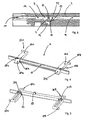
Fig. 3 gezeigte Ausnehmung 14 dient der Aufnahme einer Schutzklappe 7, wie diese inFig. 4 und 5 gezeigt ist. Die Schutzklappe 7 besteht aus einem im Wesentlichen quer verlaufenden Steg 23 und zwei dazu in einem Winkel von 90° angeordnete Verbindungsabschnitte 24a, 24b. Die Verbindungsabschnitte 24a, 24b sind in ihrer Geometrie korrespondierend zu den beiden längsverlaufenden Ausnehmungsabschnitten 16a, 16b ausgebildet, so dass diese vollständig in die längsverlaufenden Ausnehmungsabschnltte 16a, 16b eintauchen können. Ebenso ist der quer verlaufende Steg 23 im Wesentlichen in seiner Geometrie so ausgebildet, dass er vollständig in die quer verlaufenden Ausnehmungsabschnitte 15 eintauchen kann. Die beiden Verbindungsabschnitte 24a, 24b setzen sich zusammen aus einem jeweils angeordneten Lagerabschnitt 25a, 25b und einem Rampenabschnitt 26a, 26b. Somit umfasst jeder Verbindungsabschnitt 24a, 24b jeweils einen Lagerabschnitt 25a, 25b und einen Rampenabschnitt 26a, 26b. Die Lagerabschnitte 25a, 25b ragen von dem Steg 23 weg und umfassen ferner jeweils einen zylinderförmigen Nocken 27a, 27b, welcher am Ende der Lagerabschnitte 25a, 25b so angebracht ist, dass der Lagemocken nach Außen über die Lagerabschnitte 25a, 25b hinausragt. - Die Geometrie der Lagernocken entspricht den Ausnehmungen der zylinderförmigen Aussparungen 22a, 22b der korrespondieren Lagerelemente 21 a, 21 b im Kontaktträger 4 und somit in der Ausnehmung 14.
- Wie in
Fig. 5 dargestellte Unteransicht der Schutzklappe 7, gemäßFig. 4 , spannt die untere Auflagefläche 28 eine im Wesentlichen ebene Fläche auf, die im montierten Zustand auf der Auflagefläche der Ausnehmungen 14, 15, 16 aufliegt. Die Verbindungsabschnitte 24a, 24b bilden mit dem Steg 23 Kreuzungspunkte 29a, 29b. Die Teile der Verbindungsabschnitte 24a, 24b, die als Rampenabschnitte 26a, 26b von den Kreuzungspunkten 29a, 29b zum steckseitigen Ende hin ausgebildet sind, sind als trapezförmige Rampenabschnitte geformt. Das heißt, beginnend vom vordersten Ende steigen die Rampenabschnitte 26a, 26b in ihrer geometrischen Abmessung bis zu den Kreuzungspunkten 29a, 29b auf deren Höhe an, so dass sich schrägere Rampenflächen 30a. 30b an der Oberseite der Rampenabschnitte 26a, 26b befinden. Auf der Unterseite der Schutzklappe 7 befinden sich, wie inFig. 5 dargestellt, Ausnehmungen 31 a, 31 b, die nahe den Kreuzungspunkten 29a, 29b jeweils in den Verbindungsabschnitte 24a, 24b angebracht sind. Diese Ausnehmungen 31a, 31 b dienen der Aufnahme einer Drahtfeder 32. Die Ausnehmungen 31a, 31 b sind so angeordnet, dass diese parallel zur Längserstreckung des Steges 23 verlaufen und eine darin montierte Drahtfeder 32 vorzugsweise im Wesentlichen parallel zum Steg 23 eingebracht ist. Die Schutzklappe 7 wird vorzugsweise aus einem Kunststoffmaterial hergestellt, welches über flexible, elastische Eigenschaften verfügt. - Wie in
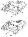
Fig. 7 gezeigt, kann die Schutzklappe 7 auf einfache Weise in den Kontaktträger 4 eingesetzt werden.Fig. 7 zeigt den Zustand kurz nachdem die Schutzklappe 7 von oben in die längsverlaufenden Ausnehmungsabschnitte 16a, 16b, beziehungsweise deren Ende, wo sich die Lagerelemente 21 a, 21 b befinden, eingesetzt werden. Dabei federn die beiden Verbindungsabschnitte 24a, 24b so aus, dass sich diese sozusagen ein Stück weit aufeinander zu bewegen und damit den Weg für die Lagernocken 27a, 27b an den Seitenwänden der Lagerelemente 21 a, 21 b freigeben, so dass die Lagemocken 27a, 27b in die dafür vorgesehene zylinderförmigen Aussparungen 22a, 22b hineinschnappen. Dieser Zustand ist inFig. 7 gezeigt. - In Folge der zylinderförmigen Ausgestaltung der Lagerbuchsen und Lagemocken lässt sich die Schutzklappe 7 um ihre Drehachse, welche parallel zum Steg 23 verläuft, drehen und in die Ausnehmung 14 einschwenken, so wie dies in
Fig. 6 gezeigt ist. - Wie in
Fig. 8 dargestellt, wird vor dem Einschwenken in die in derFig. 6 gezeigten Position eine Drahtfeder 32 in die Ausnehmungen 31 a, 31 b von unten in die Schutzklappe 7 eingesetzt. Vorzugsweise verfügen die Ausnehmungen 31a, 31b über Rastmittel 33, die dazu dienen, die Drahtfeder 32 sicher in ihrer Einsetzposition zu halten, so dass diese bei Verschwenken der Schutzklappe 7 in die inFig. 6 gezeigte Position nicht aus ihrer Lage herausrutscht. Vorzugsweise sind die Rastmittel 33 entlang der Tiefe der Ausnehmungen 31a, 31 b abgestuft, sozusagen abgetreppt angeordnet, so dass die Tiefe der Einbringposition der Drahtfeder 32 in die Ausnehmungen 31 a, 31 b bestimmt werden kann. Dies hat den Grund, dass im eingeschwenkten Zustand, wie inFig. 6 , die Biegung und damit die Federkraft der Drahtfeder bestimmt werden kann. - In
Fig. 6 gezeigt, ist die Schutzklappe 7 in ihre eigentliche Schutzstellung eingeschwenkt worden. Dabei liegt die Drahtfeder 32 auf der Auflagefläche 19 des Vorsprungs 18 auf. Die relative Position, sozusagen die Höhe der Auflagefläche 19, ist dabei so gewählt, dass es zu einer minimalen Durchbiegung der Drahtfeder 32 kommt und bedingt durch die Federkraft die Schutzklappe 7 an die Innenseite des Deckels 3 gedrückt wird. Dadurch versperrt der Steg 23 den Zugang zum Aufnahmeraum 12 von beziehungsweise durch den Einsetzschlitz 11. Dadurch wird gewährleistet, dass der Kartenleser 1 mit seinem Aufnahmeraum 12 nach Außen hin durch die Schutzklappe 7 verschlossen ist. Die Federkraft mit der die Schutzklappe 7 in ihrer Schließstellung gehalten wird, wird definiert einerseits durch die Tiefe der Einbringung der Drahtfeder 32 in die Ausnehmungen 31 a, 31 b, sowie die dazu relative Höhe der Auflagefläche 19 des Vorsprungs 18. Durch Skalierung dieser Maße kann damit die Haltekraft der Schutzklappe 7 bestimmt werden. - In
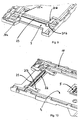
Fig. 9 und Fig. 10 sind jeweils perspektivische Ansichten der eingesetzten Schutzklappe 7 mit eingebrachter Drahtfeder 32 in den Aufnahmeraum 12 des Kartenlesers 1 gezeigt. Wie ersichtlich ist, liegt bedingt durch die Lage der Drahtfeder 32, die sich auf der Auflagefläche 19 abstützt, die Schutzklappe 7 mit ihrer Auflagefläche 28 oberhalb der Auflage der Ausnehmung 14 und hängt somit sozusagen in der Luft drehbar gelagert an den Lagemocken 27a, 27b. Bei Druck auf die Schutzklappe 7 schwenkt diese in ihre Öffnungsposition in die Ausnehmung 14 ein und gibt den Aufnahmeraum 12 zum Einsetzschlitz 11 hin frei. Diese Freigabe erfolgt dadurch, dass bei aufgebrachtem Deckel 3 auf das Gehäuse 2 ein für die Karte definierte Aufnahmeraum 12 die Karte beim Einschieben durch den Einsetzschlitz 11 auf die schräge Rampenflächen 30a, 30b führt. Beim Auftreffen der Vorderkante einer Karte auf die schrägen Rampenflächen 30a, 30b der Rampenabschnitte 26a, 26b, werden diese zwangswelse nach unten bewegt und die Schutzklappe 7 verschwenkt in ihre Öffnungsstellung. Bei weiterem Einschieben gleitet die Karte mit ihrem steckseitigen Ende solange In den Aufnahmeraum 12 ein, bis diese am hinteren Kartenanschlag 8 zum Anliegen kommt. Nach Entnahme der Karte über einen Betätigungsmechanismus 10 gleitet die Karte wieder aus dem Kartenschacht heraus und nach Erreichen der Position der Rampenabschnitte 26a, 26b wird die Schutzklappe 7 noch vor vollständiger Entnahme der Karte aus ihrer Öffnungsstellung zurück in ihre Schließstellung bedingt durch die Federkraft der Drahtfeder 32 bewegt und kommt erneut zum Anliegen an der Innenseite des Deckels 3. Dieser Zustand ist inFig. 11 dargestellt, bei einem Schnitt quer durch den erfindungsgemäßen Kartenleser und dem vorgelegten Ausführungsbeispiel. Deutlich zu erkennen, ist die Durchbiegung der Drahtfeder 32 entlang ihrer Achse. -
- 1
- Smart-Card-Connector/Kartenleser
- 2
- Gehäuse
- 3
- Deckel
- 4
- Kontaktträger
- 5
- Kontaktblock
- 6
- Kontakte
- 7
- Schutzklappe
- 8
- hinterer Kartenaufschlag
- 9
- eventuelle Kartenführung
- 10
- Betätigungsmechanismus
- 11
- Einsetzschlitz
- 12
- Aufnahmeraum
- 13
- Prüföffnungen
- 14
- Ausnehmung
- 15
- quer verlaufender Ausnehmungsabschnitt
- 16a, 16b
- längs verlaufender Ausnehmungsabschnitt
- 17a, 17b
- Kreuzungspunkte
- 18
- Vorsprung
- 19
- Auflagefläche
- 20
- Nase
- 21a, 21 b
- Lagerelemente
- 22a, 22b
- zylinderförmige Lagerbuchsen
- 23
- Steg
- 24a, 24b
- Verbindungsabschnitt
- 25a, 25b
- Lagerabschnitt
- 26a, 26b
- Rampenabschnitt
- 27a, 27b
- Lagemocken
- 28
- Auflagefläche
- 29a, 29b
- Kreuzungspunkte
- 30a, 30b
- schräge Rampenflächen
- 31a, 31b
- Ausnehmungen
- 32
- Drahtfeder
- 33
- Rastmittel
Claims (14)
- Kartenleser (1) umfassend einen Kontaktträger (4) und einen Deckel (3), welcher mit dem Kontaktträger (4) einen Aufnahmeraum (12) zur Aufnahme einer Karte bildet und einen Einsetzschlitz (11) zum Einsetzen einer Karte in den Aufnahmeraum (12) des Kartenlesers (1) bildet und wobei der Aufnahmeraum (12) durch eine Schutzklappe (7) nach Außen hin verschlossen ist, wenn sich keine Karte im Kartenleser befindet dadurch gekennzeichnet, dass die Schutzklappe (7) drehbar im Kontaktträger (4) gelagert ist und sich von einer Schließstellung in eine Öffnungsstellung entlang ihrer Drehachse verschwenken lässt.
- Kartenleser (1) gemäß Anspruch 1, dadurch gekennzeichnet, dass der Kontaktträger (4) über eine Ausnehmung (14) verfügt, in die die Schutzklappe (7) beim Einsetzten einer Karte In den Kartenleser (1) vollständig eintaucht.
- Kartenleser (1) gemäß Anspruch 1 oder 2, dadurch gekennzeichnet, dass die Schutzkappe (7) über einen Steg (23) verfügt, welcher den Aufnahmeraum (12) in der Öffnungsstellung der Schutzklappe (7) nach Außen hin verschließt und das am Steg (23) zwei Lagerabschnitte (25a, 25b) angeordnet sind, welche vom Steg (23) senkrecht zu seiner Stegachse wegragen.
- Kartenleser (1) gemäß einem der vorhergehenden Ansprüche, dadurch gekennzeichnet, dass an den Lagerabschnitten (25a, 25b) senkrecht nach Außen zylindrische Lagemocken (27a, 27b) derart angeordnet sind, dass die durch die Lagemocken (27a, 27b) gebildete Drehachse parallel zur Stegachse des Steges (23) zu liegen kommt.
- Kartenleser (1) gemäß einem der vorhergehenden Ansprüche, dadurch gekennzeichnet, dass die Schutzklappe (7) eine Drahtfeder (32) aufwelst, welche sich am Kontaktträger abstützt und die Schutzklappe (7) mit ihrer Oberseite an die Innenseite des Deckels (3) des Kartenlesers (1) drückt.
- Kartenleser (1) gemäß einem der vorhergehenden Ansprüche, dadurch gekennzeichnet, dass die Schutzklappe (7) über zwei Rampenabschnitte (26a, 26b) verfügt, wodurch die Schutzklappe (7) von einer Karte betätigbar ist und diese Ober die zwei Rampenabschnitte von ihrer Schließstellung in ihre Öffnungsstellung betätigen kann.
- Kartenleser (1) gemäß einem der vorhergehenden Ansprüche, dadurch gekennzeichnet, dass beim Einschieben einer Karte in den Kartenleser (1) die Karte mit ihrem steckseitigem Ende auf die Rampenabschnitte (26a, 26b) aufläuft und die Schutzklappe (7) dadurch betätigt, dass diese sich um ihre Drehachse von der Öffnungsstellung in die Schließstellung verschwenkt, derart, dass diese vollständig in die Ausnehmung (14) eintaucht.
- Kartenleser (1) gemäß einem der vorhergehenden Ansprüche, dadurch gekennzeichnet, dass die Schutzklappe (7) über zwei zylindrische Lagernocken (27a, 27b) verfügt, welche mit korrespondierenden Lagerbuchsen (22a, 22b) welche im Kontaktträger (4) angebracht sind, zusammenwirken und an denen die Schutzklappe (7) mit ihren Lagemocken (27a, 27b) drehbar gelagert ist.
- Kartenleser (1) gemäß einem der vorhergehenden Ansprüche, dadurch gekennzeichnet, dass die Ausnehmung (14) über einen quer verlaufenden Ausnehmungsabschnitt (15) quer zur Einsteckrichtung der Karte verfügt und über zwei dazu senkrecht orientierte in Einschubrichtung der Karte ausgebildete längsverlaufende Ausnehmungsabschnitte (16a, 16b).
- Kartenleser (1) gemäß einem der vorhergehenden Ansprüche, dadurch gekennzeichnet, dass die Ausnehmungen (14, 15, 16) im Wesentlichen als U-förmige Kastenrinne im Boden des Kontaktträgers (4) ausgebildet sind und sich die längsverlaufenden Ausnehmungsabschnitte (16a, 16b) mit dem quer verlaufenden Ausnehmungsabschnitt (15) an zwei Kreuzungspunkten (17a,17b) kreuzen.
- Kartenleser (1) gemäß einem der vorhergehenden Ansprüche, dadurch gekennzeichnet, dass die Rampenabschnitte (26a, 26b) über schräge Rampenflächen (30a, 30b) verfügen.
- Kartenleser (1) gemäß einem der vorhergehenden Ansprüche, dadurch gekennzeichnet, dass sich die Rampenabschnitte (26a, 26b) im Bereich der Kreuzungspunkte (17a, 17b) befinden, sowohl wenn sich die Schutzklappe (7) in Ihrem Öffnungszustand als auch im Schließzustand befindet.
- Kartenleser (1) gemäß einem der vorhergehenden Ansprüche, dadurch gekennzeichnet, dass ein Vorsprung (18) im Bereich der Ausnehmung (14) befindet, welcher über eine Auflagefläche (19) zur Auflage der Drahtfeder (32) verfügt.
- Kartenleser (1) gemäß einem der vorhergehenden Ansprüche, dadurch gekennzeichnet, dass der Vorsprung (18) über eine Nase (20) verfügt, welche in Richtung des Kastenaufnahmeraumes (12) ragt.
Applications Claiming Priority (1)
| Application Number | Priority Date | Filing Date | Title |
|---|---|---|---|
| DE102007062318A DE102007062318B4 (de) | 2007-12-21 | 2007-12-21 | Schmutz- und Manipulationsgeschützter Kartenleser |
Publications (2)
| Publication Number | Publication Date |
|---|---|
| EP2073148A1 true EP2073148A1 (de) | 2009-06-24 |
| EP2073148B1 EP2073148B1 (de) | 2011-05-25 |
Family
ID=40459856
Family Applications (1)
| Application Number | Title | Priority Date | Filing Date |
|---|---|---|---|
| EP08020486A Active EP2073148B1 (de) | 2007-12-21 | 2008-11-26 | Schmutz- und Manipulationsgeschützter Kartenleser |
Country Status (3)
| Country | Link |
|---|---|
| EP (1) | EP2073148B1 (de) |
| AT (1) | ATE511155T1 (de) |
| DE (1) | DE102007062318B4 (de) |
Families Citing this family (1)
| Publication number | Priority date | Publication date | Assignee | Title |
|---|---|---|---|---|
| DE102015122472B4 (de) | 2015-12-21 | 2019-03-14 | Amphenol-Tuchel Electronics Gmbh | Kontaktschutzanordnung für einen Kartenleser |
Citations (4)
| Publication number | Priority date | Publication date | Assignee | Title |
|---|---|---|---|---|
| JPH0235584A (ja) * | 1988-07-26 | 1990-02-06 | Hitachi Maxell Ltd | Icカートリツジリーダーライター |
| DE4139482A1 (de) * | 1991-11-29 | 1993-06-03 | Man Technologie Gmbh | Schutzeinrichtung fuer eletronische kartenlesegeraete |
| JP2000090205A (ja) * | 1998-09-14 | 2000-03-31 | Toshiba Corp | カード処理装置 |
| DE10213842A1 (de) * | 2002-03-27 | 2003-10-23 | Amphenol Tuchel Elect | Smart-Card Connector mit Schmutzklappe |
Family Cites Families (3)
| Publication number | Priority date | Publication date | Assignee | Title |
|---|---|---|---|---|
| DE3518247A1 (de) * | 1985-05-21 | 1986-11-27 | Siemens AG, 1000 Berlin und 8000 München | Ver- und entriegelungseinrichtung fuer einen kartenleser |
| DE19959463C2 (de) * | 1999-12-10 | 2002-05-16 | Nat Rejectors Gmbh | Kartenlesevorrichtung |
| DE10321242B4 (de) * | 2003-05-12 | 2008-04-10 | Siemens Ag | Kartenaufnahmevorrichtung |
-
2007
- 2007-12-21 DE DE102007062318A patent/DE102007062318B4/de not_active Expired - Fee Related
-
2008
- 2008-11-26 EP EP08020486A patent/EP2073148B1/de active Active
- 2008-11-26 AT AT08020486T patent/ATE511155T1/de active
Patent Citations (4)
| Publication number | Priority date | Publication date | Assignee | Title |
|---|---|---|---|---|
| JPH0235584A (ja) * | 1988-07-26 | 1990-02-06 | Hitachi Maxell Ltd | Icカートリツジリーダーライター |
| DE4139482A1 (de) * | 1991-11-29 | 1993-06-03 | Man Technologie Gmbh | Schutzeinrichtung fuer eletronische kartenlesegeraete |
| JP2000090205A (ja) * | 1998-09-14 | 2000-03-31 | Toshiba Corp | カード処理装置 |
| DE10213842A1 (de) * | 2002-03-27 | 2003-10-23 | Amphenol Tuchel Elect | Smart-Card Connector mit Schmutzklappe |
Also Published As
| Publication number | Publication date |
|---|---|
| ATE511155T1 (de) | 2011-06-15 |
| DE102007062318A1 (de) | 2009-07-02 |
| DE102007062318B4 (de) | 2010-02-18 |
| EP2073148B1 (de) | 2011-05-25 |
Similar Documents
| Publication | Publication Date | Title |
|---|---|---|
| DE69904352T2 (de) | Elektrischer verbinder für eine elektronische speicherkarte oder chipkarte | |
| EP0580890A1 (de) | Aufnahmeelement für Scheckkarten | |
| DE29811425U1 (de) | Kontaktiereinheit für ein kartenförmiges Trägerelement elektronischer Baugruppen, insbesondere nach PCMCIA-Norm | |
| EP2026241B1 (de) | Modulare SIM-Kartenlesevorrichtung mit federbelasteter Schublade | |
| DE69825412T2 (de) | ID-Kartenleser | |
| EP2659425B1 (de) | Smart card connector mit kontaktwippe | |
| DE112005003496T5 (de) | IC Träger, IC Fassung und Verfahren zum Testen einer IC Vorrichtung | |
| EP2002379A1 (de) | Kartenleser nach dem push-push-system | |
| DE69802677T2 (de) | Elektrischer verbinder für eine kontaktkarte mit integrierten schaltungen | |
| EP2073148B1 (de) | Schmutz- und Manipulationsgeschützter Kartenleser | |
| EP1738294B1 (de) | Smart card connector insbesondere mit schirmeinrichtung | |
| DE10326344B4 (de) | Kartensteckstelle | |
| EP1975848B1 (de) | Kartenleser für unterschiedliche Speicherkarten | |
| DE10213842B4 (de) | Smart-Card Connector mit Schmutzklappe | |
| DE102007057521B4 (de) | Smart-Card-Connector mit Schirmeinrichtung | |
| EP3048554B1 (de) | Vandalismusgeschützter Kartenleser | |
| EP1975853B1 (de) | Kartenlese- und/oder Schreibeinheit | |
| DE102015122472B4 (de) | Kontaktschutzanordnung für einen Kartenleser | |
| EP2472431B1 (de) | Smart Card Connector mit landenden Kontakten | |
| DE9201969U1 (de) | Verschluß für eine Plattenkassette | |
| DE3546960C2 (de) | Kontaktiereinrichtung | |
| DE69904964T2 (de) | Lesevorrichtung für eine chipkarte | |
| DE102012021672A1 (de) | Kartenkontaktiervorrichtung | |
| EP1257966A1 (de) | Kartenleser mit an schwenkarmen gelagerten transportrollen | |
| WO2003041007A1 (de) | Führungsschacht für ein chipkarten-aufnahmeaggregat |
Legal Events
| Date | Code | Title | Description |
|---|---|---|---|
| PUAI | Public reference made under article 153(3) epc to a published international application that has entered the european phase |
Free format text: ORIGINAL CODE: 0009012 |
|
| AK | Designated contracting states |
Kind code of ref document: A1 Designated state(s): AT BE BG CH CY CZ DE DK EE ES FI FR GB GR HR HU IE IS IT LI LT LU LV MC MT NL NO PL PT RO SE SI SK TR |
|
| AX | Request for extension of the european patent |
Extension state: AL BA MK RS |
|
| 17P | Request for examination filed |
Effective date: 20091228 |
|
| 17Q | First examination report despatched |
Effective date: 20100122 |
|
| AKX | Designation fees paid |
Designated state(s): AT BE BG CH CY CZ DE DK EE ES FI FR GB GR HR HU IE IS IT LI LT LU LV MC MT NL NO PL PT RO SE SI SK TR |
|
| AXX | Extension fees paid |
Extension state: RS Payment date: 20091228 Extension state: BA Payment date: 20091228 Extension state: MK Payment date: 20091228 Extension state: AL Payment date: 20091228 |
|
| GRAP | Despatch of communication of intention to grant a patent |
Free format text: ORIGINAL CODE: EPIDOSNIGR1 |
|
| GRAS | Grant fee paid |
Free format text: ORIGINAL CODE: EPIDOSNIGR3 |
|
| GRAA | (expected) grant |
Free format text: ORIGINAL CODE: 0009210 |
|
| AK | Designated contracting states |
Kind code of ref document: B1 Designated state(s): AT BE BG CH CY CZ DE DK EE ES FI FR GB GR HR HU IE IS IT LI LT LU LV MC MT NL NO PL PT RO SE SI SK TR |
|
| AX | Request for extension of the european patent |
Extension state: AL BA MK RS |
|
| REG | Reference to a national code |
Ref country code: GB Ref legal event code: FG4D Free format text: NOT ENGLISH |
|
| REG | Reference to a national code |
Ref country code: CH Ref legal event code: EP |
|
| REG | Reference to a national code |
Ref country code: IE Ref legal event code: FG4D Free format text: LANGUAGE OF EP DOCUMENT: GERMAN |
|
| REG | Reference to a national code |
Ref country code: DE Ref legal event code: R096 Ref document number: 502008003662 Country of ref document: DE Effective date: 20110707 |
|
| REG | Reference to a national code |
Ref country code: SE Ref legal event code: TRGR |
|
| REG | Reference to a national code |
Ref country code: NL Ref legal event code: T3 |
|
| PG25 | Lapsed in a contracting state [announced via postgrant information from national office to epo] |
Ref country code: LT Free format text: LAPSE BECAUSE OF FAILURE TO SUBMIT A TRANSLATION OF THE DESCRIPTION OR TO PAY THE FEE WITHIN THE PRESCRIBED TIME-LIMIT Effective date: 20110525 Ref country code: PT Free format text: LAPSE BECAUSE OF FAILURE TO SUBMIT A TRANSLATION OF THE DESCRIPTION OR TO PAY THE FEE WITHIN THE PRESCRIBED TIME-LIMIT Effective date: 20110926 Ref country code: NO Free format text: LAPSE BECAUSE OF FAILURE TO SUBMIT A TRANSLATION OF THE DESCRIPTION OR TO PAY THE FEE WITHIN THE PRESCRIBED TIME-LIMIT Effective date: 20110825 Ref country code: HR Free format text: LAPSE BECAUSE OF FAILURE TO SUBMIT A TRANSLATION OF THE DESCRIPTION OR TO PAY THE FEE WITHIN THE PRESCRIBED TIME-LIMIT Effective date: 20110525 |
|
| PG25 | Lapsed in a contracting state [announced via postgrant information from national office to epo] |
Ref country code: FI Free format text: LAPSE BECAUSE OF FAILURE TO SUBMIT A TRANSLATION OF THE DESCRIPTION OR TO PAY THE FEE WITHIN THE PRESCRIBED TIME-LIMIT Effective date: 20110525 Ref country code: SI Free format text: LAPSE BECAUSE OF FAILURE TO SUBMIT A TRANSLATION OF THE DESCRIPTION OR TO PAY THE FEE WITHIN THE PRESCRIBED TIME-LIMIT Effective date: 20110525 Ref country code: CY Free format text: LAPSE BECAUSE OF FAILURE TO SUBMIT A TRANSLATION OF THE DESCRIPTION OR TO PAY THE FEE WITHIN THE PRESCRIBED TIME-LIMIT Effective date: 20110525 Ref country code: GR Free format text: LAPSE BECAUSE OF FAILURE TO SUBMIT A TRANSLATION OF THE DESCRIPTION OR TO PAY THE FEE WITHIN THE PRESCRIBED TIME-LIMIT Effective date: 20110826 Ref country code: ES Free format text: LAPSE BECAUSE OF FAILURE TO SUBMIT A TRANSLATION OF THE DESCRIPTION OR TO PAY THE FEE WITHIN THE PRESCRIBED TIME-LIMIT Effective date: 20110905 Ref country code: LV Free format text: LAPSE BECAUSE OF FAILURE TO SUBMIT A TRANSLATION OF THE DESCRIPTION OR TO PAY THE FEE WITHIN THE PRESCRIBED TIME-LIMIT Effective date: 20110525 Ref country code: IS Free format text: LAPSE BECAUSE OF FAILURE TO SUBMIT A TRANSLATION OF THE DESCRIPTION OR TO PAY THE FEE WITHIN THE PRESCRIBED TIME-LIMIT Effective date: 20110925 |
|
| REG | Reference to a national code |
Ref country code: IE Ref legal event code: FD4D |
|
| PG25 | Lapsed in a contracting state [announced via postgrant information from national office to epo] |
Ref country code: CZ Free format text: LAPSE BECAUSE OF FAILURE TO SUBMIT A TRANSLATION OF THE DESCRIPTION OR TO PAY THE FEE WITHIN THE PRESCRIBED TIME-LIMIT Effective date: 20110525 Ref country code: EE Free format text: LAPSE BECAUSE OF FAILURE TO SUBMIT A TRANSLATION OF THE DESCRIPTION OR TO PAY THE FEE WITHIN THE PRESCRIBED TIME-LIMIT Effective date: 20110525 Ref country code: IE Free format text: LAPSE BECAUSE OF FAILURE TO SUBMIT A TRANSLATION OF THE DESCRIPTION OR TO PAY THE FEE WITHIN THE PRESCRIBED TIME-LIMIT Effective date: 20110525 |
|
| PG25 | Lapsed in a contracting state [announced via postgrant information from national office to epo] |
Ref country code: DK Free format text: LAPSE BECAUSE OF FAILURE TO SUBMIT A TRANSLATION OF THE DESCRIPTION OR TO PAY THE FEE WITHIN THE PRESCRIBED TIME-LIMIT Effective date: 20110525 Ref country code: RO Free format text: LAPSE BECAUSE OF FAILURE TO SUBMIT A TRANSLATION OF THE DESCRIPTION OR TO PAY THE FEE WITHIN THE PRESCRIBED TIME-LIMIT Effective date: 20110525 Ref country code: PL Free format text: LAPSE BECAUSE OF FAILURE TO SUBMIT A TRANSLATION OF THE DESCRIPTION OR TO PAY THE FEE WITHIN THE PRESCRIBED TIME-LIMIT Effective date: 20110525 Ref country code: SK Free format text: LAPSE BECAUSE OF FAILURE TO SUBMIT A TRANSLATION OF THE DESCRIPTION OR TO PAY THE FEE WITHIN THE PRESCRIBED TIME-LIMIT Effective date: 20110525 |
|
| PLBE | No opposition filed within time limit |
Free format text: ORIGINAL CODE: 0009261 |
|
| STAA | Information on the status of an ep patent application or granted ep patent |
Free format text: STATUS: NO OPPOSITION FILED WITHIN TIME LIMIT |
|
| 26N | No opposition filed |
Effective date: 20120228 |
|
| BERE | Be: lapsed |
Owner name: AMPHENOL-TUCHEL ELECTRONICS G.M.B.H. Effective date: 20111130 |
|
| PG25 | Lapsed in a contracting state [announced via postgrant information from national office to epo] |
Ref country code: IT Free format text: LAPSE BECAUSE OF FAILURE TO SUBMIT A TRANSLATION OF THE DESCRIPTION OR TO PAY THE FEE WITHIN THE PRESCRIBED TIME-LIMIT Effective date: 20110525 |
|
| REG | Reference to a national code |
Ref country code: DE Ref legal event code: R097 Ref document number: 502008003662 Country of ref document: DE Effective date: 20120228 |
|
| PG25 | Lapsed in a contracting state [announced via postgrant information from national office to epo] |
Ref country code: MC Free format text: LAPSE BECAUSE OF NON-PAYMENT OF DUE FEES Effective date: 20111130 |
|
| PG25 | Lapsed in a contracting state [announced via postgrant information from national office to epo] |
Ref country code: BE Free format text: LAPSE BECAUSE OF NON-PAYMENT OF DUE FEES Effective date: 20111130 |
|
| PG25 | Lapsed in a contracting state [announced via postgrant information from national office to epo] |
Ref country code: MT Free format text: LAPSE BECAUSE OF FAILURE TO SUBMIT A TRANSLATION OF THE DESCRIPTION OR TO PAY THE FEE WITHIN THE PRESCRIBED TIME-LIMIT Effective date: 20110525 |
|
| PG25 | Lapsed in a contracting state [announced via postgrant information from national office to epo] |
Ref country code: LU Free format text: LAPSE BECAUSE OF NON-PAYMENT OF DUE FEES Effective date: 20111126 |
|
| PG25 | Lapsed in a contracting state [announced via postgrant information from national office to epo] |
Ref country code: BG Free format text: LAPSE BECAUSE OF FAILURE TO SUBMIT A TRANSLATION OF THE DESCRIPTION OR TO PAY THE FEE WITHIN THE PRESCRIBED TIME-LIMIT Effective date: 20110825 |
|
| REG | Reference to a national code |
Ref country code: CH Ref legal event code: PL |
|
| PG25 | Lapsed in a contracting state [announced via postgrant information from national office to epo] |
Ref country code: CH Free format text: LAPSE BECAUSE OF NON-PAYMENT OF DUE FEES Effective date: 20121130 Ref country code: LI Free format text: LAPSE BECAUSE OF NON-PAYMENT OF DUE FEES Effective date: 20121130 |
|
| PG25 | Lapsed in a contracting state [announced via postgrant information from national office to epo] |
Ref country code: TR Free format text: LAPSE BECAUSE OF FAILURE TO SUBMIT A TRANSLATION OF THE DESCRIPTION OR TO PAY THE FEE WITHIN THE PRESCRIBED TIME-LIMIT Effective date: 20110525 |
|
| PG25 | Lapsed in a contracting state [announced via postgrant information from national office to epo] |
Ref country code: HU Free format text: LAPSE BECAUSE OF FAILURE TO SUBMIT A TRANSLATION OF THE DESCRIPTION OR TO PAY THE FEE WITHIN THE PRESCRIBED TIME-LIMIT Effective date: 20110525 |
|
| REG | Reference to a national code |
Ref country code: AT Ref legal event code: MM01 Ref document number: 511155 Country of ref document: AT Kind code of ref document: T Effective date: 20131126 |
|
| PG25 | Lapsed in a contracting state [announced via postgrant information from national office to epo] |
Ref country code: AT Free format text: LAPSE BECAUSE OF NON-PAYMENT OF DUE FEES Effective date: 20131126 |
|
| REG | Reference to a national code |
Ref country code: FR Ref legal event code: PLFP Year of fee payment: 8 |
|
| REG | Reference to a national code |
Ref country code: FR Ref legal event code: PLFP Year of fee payment: 9 |
|
| REG | Reference to a national code |
Ref country code: FR Ref legal event code: PLFP Year of fee payment: 10 |
|
| PGFP | Annual fee paid to national office [announced via postgrant information from national office to epo] |
Ref country code: NL Payment date: 20201119 Year of fee payment: 13 |
|
| PGFP | Annual fee paid to national office [announced via postgrant information from national office to epo] |
Ref country code: GB Payment date: 20201123 Year of fee payment: 13 Ref country code: FR Payment date: 20201120 Year of fee payment: 13 |
|
| PGFP | Annual fee paid to national office [announced via postgrant information from national office to epo] |
Ref country code: SE Payment date: 20211123 Year of fee payment: 14 Ref country code: DE Payment date: 20211122 Year of fee payment: 14 |
|
| REG | Reference to a national code |
Ref country code: NL Ref legal event code: MM Effective date: 20211201 |
|
| GBPC | Gb: european patent ceased through non-payment of renewal fee |
Effective date: 20211126 |
|
| PG25 | Lapsed in a contracting state [announced via postgrant information from national office to epo] |
Ref country code: NL Free format text: LAPSE BECAUSE OF NON-PAYMENT OF DUE FEES Effective date: 20211201 |
|
| PG25 | Lapsed in a contracting state [announced via postgrant information from national office to epo] |
Ref country code: GB Free format text: LAPSE BECAUSE OF NON-PAYMENT OF DUE FEES Effective date: 20211126 |
|
| PG25 | Lapsed in a contracting state [announced via postgrant information from national office to epo] |
Ref country code: FR Free format text: LAPSE BECAUSE OF NON-PAYMENT OF DUE FEES Effective date: 20211130 |
|
| REG | Reference to a national code |
Ref country code: DE Ref legal event code: R119 Ref document number: 502008003662 Country of ref document: DE |
|
| REG | Reference to a national code |
Ref country code: SE Ref legal event code: EUG |
|
| PG25 | Lapsed in a contracting state [announced via postgrant information from national office to epo] |
Ref country code: SE Free format text: LAPSE BECAUSE OF NON-PAYMENT OF DUE FEES Effective date: 20221127 |
|
| PG25 | Lapsed in a contracting state [announced via postgrant information from national office to epo] |
Ref country code: DE Free format text: LAPSE BECAUSE OF NON-PAYMENT OF DUE FEES Effective date: 20230601 |