EP2072854A2 - Suspension and straddle-type vehicle - Google Patents
Suspension and straddle-type vehicle Download PDFInfo
- Publication number
- EP2072854A2 EP2072854A2 EP08253907A EP08253907A EP2072854A2 EP 2072854 A2 EP2072854 A2 EP 2072854A2 EP 08253907 A EP08253907 A EP 08253907A EP 08253907 A EP08253907 A EP 08253907A EP 2072854 A2 EP2072854 A2 EP 2072854A2
- Authority
- EP
- European Patent Office
- Prior art keywords
- cylinder
- spring
- oil
- adjustment mechanism
- oil chamber
- Prior art date
- Legal status (The legal status is an assumption and is not a legal conclusion. Google has not performed a legal analysis and makes no representation as to the accuracy of the status listed.)
- Granted
Links
- 239000000725 suspension Substances 0.000 title claims abstract description 55
- 230000002093 peripheral effect Effects 0.000 claims abstract description 54
- 238000013016 damping Methods 0.000 claims description 54
- 238000005266 casting Methods 0.000 claims description 3
- 230000003247 decreasing effect Effects 0.000 description 5
- 238000010586 diagram Methods 0.000 description 3
- 238000004519 manufacturing process Methods 0.000 description 3
- IJGRMHOSHXDMSA-UHFFFAOYSA-N Atomic nitrogen Chemical compound N#N IJGRMHOSHXDMSA-UHFFFAOYSA-N 0.000 description 2
- 230000000052 comparative effect Effects 0.000 description 2
- 239000002828 fuel tank Substances 0.000 description 2
- 238000005192 partition Methods 0.000 description 2
- 230000003746 surface roughness Effects 0.000 description 2
- 239000000470 constituent Substances 0.000 description 1
- 238000010276 construction Methods 0.000 description 1
- 239000007789 gas Substances 0.000 description 1
- 238000009434 installation Methods 0.000 description 1
- 229910052757 nitrogen Inorganic materials 0.000 description 1
Images


Classifications
-
- F—MECHANICAL ENGINEERING; LIGHTING; HEATING; WEAPONS; BLASTING
- F16—ENGINEERING ELEMENTS AND UNITS; GENERAL MEASURES FOR PRODUCING AND MAINTAINING EFFECTIVE FUNCTIONING OF MACHINES OR INSTALLATIONS; THERMAL INSULATION IN GENERAL
- F16F—SPRINGS; SHOCK-ABSORBERS; MEANS FOR DAMPING VIBRATION
- F16F9/00—Springs, vibration-dampers, shock-absorbers, or similarly-constructed movement-dampers using a fluid or the equivalent as damping medium
- F16F9/32—Details
- F16F9/44—Means on or in the damper for manual or non-automatic adjustment; such means combined with temperature correction
-
- B—PERFORMING OPERATIONS; TRANSPORTING
- B60—VEHICLES IN GENERAL
- B60G—VEHICLE SUSPENSION ARRANGEMENTS
- B60G17/00—Resilient suspensions having means for adjusting the spring or vibration-damper characteristics, for regulating the distance between a supporting surface and a sprung part of vehicle or for locking suspension during use to meet varying vehicular or surface conditions, e.g. due to speed or load
- B60G17/02—Spring characteristics, e.g. mechanical springs and mechanical adjusting means
- B60G17/027—Mechanical springs regulated by fluid means
- B60G17/0272—Mechanical springs regulated by fluid means the mechanical spring being a coil spring
-
- B—PERFORMING OPERATIONS; TRANSPORTING
- B62—LAND VEHICLES FOR TRAVELLING OTHERWISE THAN ON RAILS
- B62K—CYCLES; CYCLE FRAMES; CYCLE STEERING DEVICES; RIDER-OPERATED TERMINAL CONTROLS SPECIALLY ADAPTED FOR CYCLES; CYCLE AXLE SUSPENSIONS; CYCLE SIDE-CARS, FORECARS, OR THE LIKE
- B62K25/00—Axle suspensions
- B62K25/04—Axle suspensions for mounting axles resiliently on cycle frame or fork
- B62K25/28—Axle suspensions for mounting axles resiliently on cycle frame or fork with pivoted chain-stay
- B62K25/283—Axle suspensions for mounting axles resiliently on cycle frame or fork with pivoted chain-stay for cycles without a pedal crank, e.g. motorcycles
-
- B—PERFORMING OPERATIONS; TRANSPORTING
- B62—LAND VEHICLES FOR TRAVELLING OTHERWISE THAN ON RAILS
- B62K—CYCLES; CYCLE FRAMES; CYCLE STEERING DEVICES; RIDER-OPERATED TERMINAL CONTROLS SPECIALLY ADAPTED FOR CYCLES; CYCLE AXLE SUSPENSIONS; CYCLE SIDE-CARS, FORECARS, OR THE LIKE
- B62K25/00—Axle suspensions
- B62K25/04—Axle suspensions for mounting axles resiliently on cycle frame or fork
- B62K25/28—Axle suspensions for mounting axles resiliently on cycle frame or fork with pivoted chain-stay
- B62K25/286—Axle suspensions for mounting axles resiliently on cycle frame or fork with pivoted chain-stay the shock absorber being connected to the chain-stay via a linkage mechanism
-
- F—MECHANICAL ENGINEERING; LIGHTING; HEATING; WEAPONS; BLASTING
- F16—ENGINEERING ELEMENTS AND UNITS; GENERAL MEASURES FOR PRODUCING AND MAINTAINING EFFECTIVE FUNCTIONING OF MACHINES OR INSTALLATIONS; THERMAL INSULATION IN GENERAL
- F16F—SPRINGS; SHOCK-ABSORBERS; MEANS FOR DAMPING VIBRATION
- F16F9/00—Springs, vibration-dampers, shock-absorbers, or similarly-constructed movement-dampers using a fluid or the equivalent as damping medium
- F16F9/32—Details
- F16F9/3207—Constructional features
- F16F9/3235—Constructional features of cylinders
- F16F9/3242—Constructional features of cylinders of cylinder ends, e.g. caps
-
- F—MECHANICAL ENGINEERING; LIGHTING; HEATING; WEAPONS; BLASTING
- F16—ENGINEERING ELEMENTS AND UNITS; GENERAL MEASURES FOR PRODUCING AND MAINTAINING EFFECTIVE FUNCTIONING OF MACHINES OR INSTALLATIONS; THERMAL INSULATION IN GENERAL
- F16F—SPRINGS; SHOCK-ABSORBERS; MEANS FOR DAMPING VIBRATION
- F16F9/00—Springs, vibration-dampers, shock-absorbers, or similarly-constructed movement-dampers using a fluid or the equivalent as damping medium
- F16F9/32—Details
- F16F9/56—Means for adjusting the length of, or for locking, the spring or damper, e.g. at the end of the stroke
-
- B—PERFORMING OPERATIONS; TRANSPORTING
- B60—VEHICLES IN GENERAL
- B60G—VEHICLE SUSPENSION ARRANGEMENTS
- B60G2202/00—Indexing codes relating to the type of spring, damper or actuator
- B60G2202/40—Type of actuator
- B60G2202/41—Fluid actuator
- B60G2202/413—Hydraulic actuator
-
- B—PERFORMING OPERATIONS; TRANSPORTING
- B60—VEHICLES IN GENERAL
- B60G—VEHICLE SUSPENSION ARRANGEMENTS
- B60G2300/00—Indexing codes relating to the type of vehicle
- B60G2300/12—Cycles; Motorcycles
-
- B—PERFORMING OPERATIONS; TRANSPORTING
- B60—VEHICLES IN GENERAL
- B60G—VEHICLE SUSPENSION ARRANGEMENTS
- B60G2500/00—Indexing codes relating to the regulated action or device
- B60G2500/30—Height or ground clearance
-
- B—PERFORMING OPERATIONS; TRANSPORTING
- B62—LAND VEHICLES FOR TRAVELLING OTHERWISE THAN ON RAILS
- B62K—CYCLES; CYCLE FRAMES; CYCLE STEERING DEVICES; RIDER-OPERATED TERMINAL CONTROLS SPECIALLY ADAPTED FOR CYCLES; CYCLE AXLE SUSPENSIONS; CYCLE SIDE-CARS, FORECARS, OR THE LIKE
- B62K2201/00—Springs used in cycle frames or parts thereof
- B62K2201/08—Fluid springs
Definitions
- the present invention relates to a suspension apparatus including a damper, a spring adjuster, and a spring, and a straddle-type vehicle mounted with the suspension.
- a suspension is used for a rear cushion unit for a two-wheeled vehicle or the like.
- the suspension like this includes a suspension provided with a damper, a spring, and a spring adjuster (mechanism for adjusting a spring load).
- the suspension like this is disclosed in, for example, Japanese Utility Model No. 2573071 and Japanese Examined Utility Model Publication No. 7-12746 .
- the outline of the suspension disclosed in these patent documents will be described.
- the damper has a spring seat disposed on the outer periphery of a cylinder, has a spring receiver (spring seat) disposed on a piston rod side, and has a suspension spring interposed between the spring seat and the spring receiver (spring seat).
- an oil pressure jack (spring adjuster) fixed to the outer periphery of the cylinder supports the spring seat disposed on the outer periphery of the cylinder.
- the spring adjuster changes the position of the spring seat disposed on the outer periphery of the cylinder to change the spring load of the suspension spring.
- the oil pressure jack (spring adjuster) is constructed of: an oil chamber disposed in a thick portion of the cylinder; and a plunger housed in this oil chamber, and the plunger supports the spring seat.
- a damper cylinder has an annular guide fixed to the outer periphery thereof.
- An annular oil chamber is formed between the outer periphery of the damper cylinder and the annular guide.
- a sliding member is constructed so as to be displaced in the axial direction when the sliding member has oil pressure applied thereto.
- the base end portion of a piston rod and the sliding member have spring seats fixed thereto, respectively, and the base end portion of a piston rod and the sliding member have a suspension spring (spring) fixed thereto, respectively.
- the oil chamber is disposed in the thick portion of the cylinder, and the shape of the cylinder is complicate, so that the spring adjuster is hard to manufacture.
- the oil chamber is disposed between the outer periphery of the damper cylinder and the annular guide. In this structure, many seals for the oil chamber are required, so that the spring adjuster is hard to manufacture.
- the present invention proposes a suspension having an advantage in manufacture by employing a whole new structure for the oil chamber of the spring adjuster.
- a suspension apparatus (hereinafter also referred to as a suspension for conciseness) includes: a damper; a spring adjuster; and a spring.
- the damper includes: a cylinder; a cap for covering an opening at one end of the cylinder; a piston fitted in the cylinder; and a piston rod extending from the piston to the other end side of the cylinder.
- the cap has a cover portion that is opposed to the outer peripheral surface of one end portion of the cylinder and which covers the one end portion of the cylinder.
- the spring adjuster includes: an oil chamber formed in a peripheral groove between the inner peripheral surface of the cover portion and the outer peripheral surface of the one end portion of the cylinder; and a ring-shaped piston fitted in the oil chamber.
- the spring is disposed in a compressed state between a first spring seat formed on the ring-shaped piston and a second spring seat fixed to the tip portion of the piston rod.
- the cap for covering the opening at one end of the cylinder has the cover portion that is opposed to the outer peripheral surface of the one end portion of the cylinder and which covers the one end portion of the cylinder.
- the oil chamber of the spring adjuster is formed in the peripheral groove between the inner peripheral surface of the cover portion and the outer peripheral surface of the one end portion of the cylinder.
- This suspension 100 is used for a rear cushion unit of a straddle-type vehicle 10.
- the straddle-type vehicle 10 has a rear wheel 13 mounted on the tip portion of a swing arm 12 fixed to a vehicle body frame 11 so as to freely swing.
- the suspension 100 has its one end fixed to the vehicle body frame 11 and has the other end fixed to a swing mechanism 14 of the swing arm 12.
- the straddle-type vehicle 10 has a seat 21 fixed to the top of the vehicle body frame 11 and has a fuel tank 22 disposed forward of the seat 21 and has a driving unit 23 such as an engine disposed in a space under the fuel tank 22.
- This suspension 100 is provided with a damper 101, a spring adjuster 102, and a spring 103.
- the damper 101 is provided with a cylinder 111, a cap 112, a piston 113, and a piston rod 114.
- the cylinder 111 in this embodiment, is a member shaped like a circular cylinder, and an opening 111a at one end of the cylinder 111 is covered with the cap 112.
- an oil chamber 120 of the damper 101 is formed in a space surrounded by the one end of the cylinder 111 and the piston 113.
- the cylinder 111 has the spring adjuster 102 disposed outside one end portion thereof, and the cylinder 111 has a sleeve 115 fitted on the outer periphery of the one end portion thereof.
- the piston 113 is fitted in the cylinder 111.
- the piston 113 is provided with two members 121, 122 fixed to positions separate in the axial direction of the piston rod 114.
- a first member 121 disposed on one end side of the cylinder 111 does not completely partition the oil chamber 120 of the damper 101 formed in the cylinder 111, but has a passing portion 123, through which medium can pass, formed in a portion thereof.
- a second member 122 disposed on the other end side of the cylinder 111 has a seal 124 interposed between itself and the inner peripheral surface of the cylinder 111 to thereby completely partition the oil chamber 120 of the damper 101.
- the piston 113 is guided by the cylinder 111 and is slidably fitted in the cylinder in the axial direction of the cylinder 111.
- the oil chamber 120 has medium enclosed therein, the medium producing viscous resistance.
- the medium in the oil chamber 120 applies resistance to the movement of the piston 113 to effectively damp an impact inputted to the suspension 100.
- the piston rod 114 extends to the other end side of the cylinder 111 from the piston 113.
- the cylinder 111 has a closing member 131 fixed to an opening on the other end thereof, the closing member 131 closing the opening.
- the closing member 131 has a passing hole 132 formed therein, the passing hole 132 having the piston rod 114 passed therethrough.
- the cylinder 111 has a stopper 133 fixed on the inner peripheral surface thereof.
- the stopper 133 defines a range in which the piston 113 moves on the other end side of the cylinder 111.
- the piston rod 114 has a fixing part 142 disposed on its tip portion, and this suspension 100 has the fixing part 142 fixed to the swing arm 12 of the straddle-type vehicle 10.
- the fixing part 142 has a passing hole 142a formed therein, the passing hole 142a having a bolt passed therethrough.
- the cap 112 covers the opening 111a of one end of the cylinder 111 and forms the oil chamber 120 of the damper 101.
- the cap 112 has a fixing portion 141 formed thereon, the fixing portion 141 being fixed to the straddle-type vehicle 10.
- the fixing portion 141 has a fixing hole 141a formed therein, the fixing hole 141a having a bolt passed therethrough.
- the cap 112 is provided with a first damping adjustment mechanism 171 and a second damping adjustment mechanism 172, the first damping adjustment mechanism 171 adjusting the amount of oil in the oil chamber 120 (in the cylinder) of the damper 101, the second damping adjustment mechanism 172 adjusting the amount of oil in an oil chamber 140 of the spring adjuster 102.
- the cap 112 has an oil passage 173 and an oil passage 174 formed therein, the oil passage 173 connecting the first damping adjustment mechanism 171 to the oil chamber 120 of the damper 101, the oil passage 174 connecting the second damping adjustment mechanism 172 to the oil chamber 140 of the spring adjuster 102.
- the first damping adjustment mechanism 171 and the second damping adjustment mechanism 172 will be described later.
- a first seal 143 is fitted between the peripheral end portion of the opening 111a of one end of the cylinder 111 and the cap 112.
- the cap 112 extends in the axial direction along the outer peripheral surface of the cylinder 111
- a second seal 144 is fitted between the cap 112 and the outer peripheral surface of one end portion of the cylinder 111 (the outer peripheral surface of a sleeve 115, in this embodiment).
- the cap 112 is further provided with a cover portion 145 for covering the outer periphery of one end portion of the cylinder 111.
- a peripheral groove 146 is formed between the inner peripheral surface of the cover portion 145 and the outer peripheral surface of the one end portion of the cylinder 111 (the outer peripheral surface of the sleeve 115, in this embodiment).
- the cover portion 145 is opposed to the outer peripheral surface of the one end portion of the cylinder 111 with a small clearance between them by a step 147 formed on the inner periphery of the cap 112.
- the peripheral groove 146 is formed between the inner peripheral surface of the cover portion 145 and the outer peripheral surface of the one end portion of the cylinder 111 (the outer peripheral surface of the sleeve 115, in this embodiment). Moreover, the step 147 formed on the inner periphery of the cap 112 forms the bottom portion of the peripheral groove 146. Further, the bottom portion of the peripheral groove 146, as described above, is sealed by the seal 144 fitted between the cap 112 and the outer peripheral surface of the sleeve 115. Still further, in this embodiment, the sleeve 115 is fitted on the outer peripheral surface of the one end portion of the cylinder 111, and the outer peripheral surface of the sleeve 115 has a specified surface roughness.
- the cap 112 is molded by casting, and the inner peripheral surface of the cap 112, in particular, a portion forming the peripheral groove 146 surely has a specified surface roughness provided by cutting.
- the spring adjuster 102 has the oil chamber 140 formed in the peripheral groove 146.
- the oil chamber 140 has a ring-shaped piston 150 fitted therein.
- the ring-shaped piston 150 is slidably fitted in the peripheral groove 146 so as to seal the oil chamber 140.
- the ring-shaped piston 150 has a first seal 148 fitted inside, the first seal 148 sliding on the inner peripheral surface of the cover portion 145.
- the ring-shaped piton 150 has a second seal 149 fitted outside, the second seal 149 sliding on the outer peripheral surface of the cylinder 111 (the outer peripheral surface of the sleeve 115, in this embodiment).
- the oil chamber 140 of the spring adjuster 102 is sealed by the first seal 148 and the second seal 149.
- the ring-shaped piston 150 has a receiving portion 151 formed thereon, the receiving portion 151 receiving a first spring seat 161.
- the ring-shaped piston 150 is moved outward and inward by the amount of oil in the oil chamber 140 of the spring adjuster 102, whereby the position of the first spring seat 161 is changed.
- the spring 103 is disposed in a compressed state between the first spring seat 161 fixed to the receiving portion 151 and a second spring seat 162 fixed to the tip portion of the piston rod 114 of the damper 101.
- the amount of oil in the oil chamber 140 of the spring adjuster 102 is increased, the ring-shaped piston 150 and the first spring seat 161 are moved outward from the peripheral groove 146. At this time, the spring 103 is contracted and hence is stiffened. Contrarily, the amount of oil in the oil chamber 140 of the spring adjuster 102 is decreased, the ring-shaped piston 150 and the first spring seat 161 is moved inward in the peripheral groove 146. At this time, the spring 103 is elongated by the amount and hence is softened.
- the stiffness of the spring 103 is adjusted according to pressure in the oil chamber 140 of the spring adjuster 102.
- the first spring seat 161 has a scale 160 placed on the outside surface thereof at a position where the first spring seat 161 overlaps the cover portion 145.
- the spring adjuster 102 can be adjusted while looking at the scale 160.
- the spring adjuster 102 is adjusted by the second damping adjustment mechanism 172 to be described later.
- the scale 160 is placed on the outside surface of the first spring seat 161 that can be seen from the cover portion 145.
- the scale 160 may be placed on the ring-shaped piston 150, depending on the mounting structure of the ring-shaped piton 150 and the first spring seat 161.
- the first damping adjustment mechanism 171 is a mechanism for adjusting the stiffness (damping performance) of the damper 101. That is, in this embodiment, the stiffness of the damper 101 (damping performance) is adjusted by adjusting the amount of oil in the oil chamber 120 of the damper 101. The amount of oil in the oil chamber 120 of the damper 101 is adjusted by the first damping adjustment mechanism 171.
- the first damping adjustment mechanism 171 is provided with a check valve 181 and a pressure adjusting part 182.
- the check valve 181 is constructed in a cylinder-type container.
- the pressure adjusting part 182 connects to the oil chamber 120 of the damper 101 through an oil passage 173 formed in the cap 112 and the check valve 181.
- the pressure adjusting part 182, in this embodiment, is provided with an oil chamber 180 connecting to the oil chamber 120 of the damper 101 through the check valve 181.
- the oil chamber 180 has a balloon 183 housed therein and has oil packed around the balloon 183, the balloon 183 being packed with gas (nitrogen, in this embodiment) so as to keep a specified pressure.
- the check valve 181 when oil pressure in the oil chamber 120 of the damper 101 becomes a specified value or more, the check valve 181 is opened to let the oil in the oil camber 120 into the oil chamber 180 of the pressure adjusting part 182. Moreover, also when the oil pressure in the oil chamber 120 of the damper 101 is a specified value or less and the oil pressure in the oil chamber 180 of the pressure adjusting part 182 is a specified value or more, the check valve 181 is opened to let the oil into the damper 101 from the pressure adjusting part 182.
- the pressure of opening the check valve 181, in this embodiment, can be adjusted by operating an adjusting screw 185 fitted in one end portion of the check valve 181 provided with a cylinder-shaped container.
- This first damping adjusting mechanism 171 can adjust the amount of oil in the oil chamber 120 of the damper 101 by adjusting the pressure at which the check valve 181 is opened.
- the damper 101 is stiffened, whereas when the amount of oil in the oil chamber 120 of the damper 101 is decreased, the damper 101 is softened.
- the damper 101 is softened.
- the straddle-type vehicle 10 runs mainly in an urban district, the straddle-type vehicle 10 is used at low speeds, so it suffices to adjust the damper 101 to becoming soft.
- the straddle-type vehicle 10 is used at high speeds or in a race, it suffices to adjust the damper 101 to becoming stiff.
- the second damping adjustment mechanism 172 adjusts the spring adjuster 102.
- the second damping adjustment mechanism 172 as shown in Fig. 3 and Fig. 4 , is provided with a cylinder 191, a piston 192, and a position adjusting mechanism 193 for adjusting the position of the piston 192.
- the cylinder 191 is a cylindrical member having a bottom and has the piston 192 fitted therein.
- the piston 192 has a groove 201 formed in an axial direction on the outer peripheral surface thereof, whereas the cylinder 191 has a screw hole formed in a radial direction.
- the screw hole has a screw 202 fitted therein, and the tip of the screw 202 is fitted in the groove 201 formed in the piston 192.
- the screw 202 is engaged with the groove 201, so that the piston 192 cannot be rotated with respect to the cylinder 191.
- the screw hole is sealed by a seal 203.
- the piston 192 has a hollow portion having a female screw 205 formed in the axial direction.
- the position adjusting mechanism 193 is provided with a cap 210 fitted in the opening of the cylinder 191 and an adjusting screw 211 supported by the cap 210 and engaged with the female screw 205 formed in the hollow portion of the piston 192.
- the adjusting screw 211 is constructed of: a male screw shaft 212 engaged with the female screw 205 formed in the hollow portion of the piston 192; and an operating part 213 that is fixed to one end of the male screw shaft 212 and which operates the male screw shaft 212.
- the male screw shaft 212 of the adjusting screw 211 is rotated by rotating the operating part 213.
- the piston 192 has the screw 202 fitted in the groove 201 formed in the axial direction on its outer peripheral surface, the screw 202 being fitted in the cylinder 191. Hence, the piston 192 is not rotated with respect to the cylinder 191.
- the male screw shaft 212 of the position adjusting mechanism 193 is rotated, the female screw 205 formed on the piston 192 is engaged with the male screw shaft 212.
- the piston 192 is moved back and forth with respect to the cylinder 191 according to the pitch of the screw.
- An oil chamber 200 is formed in a space surrounded by the cylinder 191 and the piston 192.
- the oil chamber 200 is sealed by a seal 215 fitted on the outer peripheral surface of the piston 192.
- the oil chamber 200 connects to the oil chamber 140 of the spring adjuster 102 through the oil passage 174 formed in the cap 112 of the suspension 100 (see Fig. 2 ).
- the volume of the oil chamber 200 of the second damping adjustment mechanism 172 is increased and decreased. That is, when the piston 192 is pressed into the cylinder 191, the volume of the oil chamber 200 of the second damping adjustment mechanism 172 is decreased to let the oil in the oil chamber 200 into the oil chamber 140 of the spring adjuster 102. With this, pressure in the oil chamber 140 of the spring adjuster 102 is increased to adjust the spring 103 to becoming stiff.
- this suspension 100 the stiffness (damping performance) of the damper 101 can be adjusted by the first damping adjustment mechanism 171 for adjusting the amount of oil in the cylinder of the damper 101. Further, the stiffness of the spring 103 can be adjusted by the second damping adjustment mechanism 172 for adjusting the amount of oil in the oil chamber 140 of the spring adjuster 102.
- the cap 112 for covering the opening at one end of the cylinder 111 is provided with the cover portion 145 that is opposed to the outer peripheral surface of the one end portion of the cylinder 111 with a small gap between them and which covers the one end portion of the cylinder 111.
- the oil chamber 140 of the spring adjuster 102 is formed in the peripheral groove 146 between the inner peripheral surface of the cover portion 145 and the outer peripheral surface of the one end portion of the cylinder 111 (outer peripheral surface of the sleeve 115, in this embodiment). It suffices for the cylinder 111 to be formed in a simple shape, and the cap 112 including the cover portion 145 is formed in a shape to be manufactured with comparative ease. In this embodiment, the cap 112 is formed in the shape to be easily formed in this manner, so that the cap 112 is molded by casting. With this, the suspension 100 can be manufactured at relatively low cost.
- the first damping adjustment mechanism 171 and the second damping adjustment mechanism 172 are respectively provided with containers each formed in the shape of a cylinder, and have the longitudinal directions of the cylinders arranged in the same direction. With this, this suspension 100 has an installation space reduced.
- the cap 112 of the damper 101 has holes, in which the cylinders of the first damping adjustment mechanism 171 and the second damping adjustment mechanism 172 are fitted, formed therein in such a way that the cylinders point in the same direction.
- the fitting holes can be formed, for example, when the cap 112 is cast.
- the adjusting screw 185 disposed in one end of the check valve 181 of the first damping adjustment mechanism 171 and the operating part 213 disposed in one end of the second damping adjustment mechanism 172 are arranged on the same side.
- the adjusting screw 185 of the check valve 181 of the first damping adjustment mechanism 171 (see Fig. 2 ) and the operating part 213 of the second damping adjustment mechanism 172 (see Fig. 2 ) can be operated from a space under the seat. With this, the space required for adjusting the suspension 100 can be reduced.
- the oil passage 173 for connecting the oil chamber 120 of the damper 101 to the oil chamber 180 of the first damping adjustment mechanism 171 and the oil passage 174 for connecting the oil chamber 140 of the spring adjuster 102 to the oil chamber 200 of the second damping adjustment mechanism 172 are formed in the cap 112, respectively.
- the shape of the cap 112 is shallow in depth from the opening and is wide in the opening, so that the oil passages 173 and 174 can be formed with comparative ease by the use of a drill or the like.
- the suspension is used for the rear cushion unit of the straddle-type vehicle, and as for the straddle-type vehicle, the suspension can be used for the cushion unit of a vehicle such as a four-wheeled buggy. In this case, the suspension can be used for a cushion unit of a front wheel.
- the straddle-type vehicle includes various kinds of motorcycles, for example, a scooter-type motorcycle, a motor cycle (motorbike).
- the straddle-type vehicle includes a vehicle in which at least one of the front wheel and the rear wheel has two wheels, for example, in addition to the motorcycle, a four-wheeled buggy (ATV: All Terrain Vehicle) and a snowmobile. Still further, this suspension can be used not only for the straddle-type vehicle but also for the cushion units (dampers) for various uses.
- ATV All Terrain Vehicle
Abstract
Description
- The present invention relates to a suspension apparatus including a damper, a spring adjuster, and a spring, and a straddle-type vehicle mounted with the suspension.
- A suspension is used for a rear cushion unit for a two-wheeled vehicle or the like. The suspension like this includes a suspension provided with a damper, a spring, and a spring adjuster (mechanism for adjusting a spring load). The suspension like this is disclosed in, for example, Japanese Utility Model No.
2573071 7-12746 - In an oil damping unit (suspension) disclosed in Japanese Utility Model No.
2573071 - Moreover, in a suspension (rear cushion unit) disclosed in Japanese Examined Utility Model Publication No.
7-12746 - In the spring adjuster described in Japanese Utility Model No.
2573071 - A suspension apparatus (hereinafter also referred to as a suspension for conciseness) includes: a damper; a spring adjuster; and a spring. The damper includes: a cylinder; a cap for covering an opening at one end of the cylinder; a piston fitted in the cylinder; and a piston rod extending from the piston to the other end side of the cylinder. The cap has a cover portion that is opposed to the outer peripheral surface of one end portion of the cylinder and which covers the one end portion of the cylinder. Moreover, the spring adjuster includes: an oil chamber formed in a peripheral groove between the inner peripheral surface of the cover portion and the outer peripheral surface of the one end portion of the cylinder; and a ring-shaped piston fitted in the oil chamber. The spring is disposed in a compressed state between a first spring seat formed on the ring-shaped piston and a second spring seat fixed to the tip portion of the piston rod.
- According to this suspension, the cap for covering the opening at one end of the cylinder has the cover portion that is opposed to the outer peripheral surface of the one end portion of the cylinder and which covers the one end portion of the cylinder. The oil chamber of the spring adjuster is formed in the peripheral groove between the inner peripheral surface of the cover portion and the outer peripheral surface of the one end portion of the cylinder. Thus, the spring adjuster can be easily manufactured.
- Embodiments of the invention are described hereinafter, by way of example only, with reference to the drawings.
-
Fig. 1 is a side view to show the fixing structure of a suspension of a straddle-type vehicle according to one embodiment of the present invention -
Fig. 2 is a diagram to show the suspension according to the one embodiment of the present invention -
Fig. 3 is a diagram to show a second damping adjustment mechanism of the suspension according to the one embodiment of the present invention -
Fig. 4 is a diagram to show the state of use of the second damping adjustment mechanism of the suspension according to the one embodiment of the present invention - Hereinafter, a suspension according to embodiments of the present invention will be described with reference to the accompanying drawings. Here, in the respective drawings, the members and parts performing the same functions are denoted by the same reference symbols. The present invention is not limited to the following embodiments.
- This
suspension 100, as shown inFig. 1 , is used for a rear cushion unit of a straddle-type vehicle 10. In this embodiment, the straddle-type vehicle 10 has arear wheel 13 mounted on the tip portion of aswing arm 12 fixed to avehicle body frame 11 so as to freely swing. Thesuspension 100 has its one end fixed to thevehicle body frame 11 and has the other end fixed to aswing mechanism 14 of theswing arm 12. Here, as shown inFig. 1 , in this embodiment, the straddle-type vehicle 10 has aseat 21 fixed to the top of thevehicle body frame 11 and has afuel tank 22 disposed forward of theseat 21 and has adriving unit 23 such as an engine disposed in a space under thefuel tank 22. - This
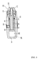
suspension 100, as shown inFig. 2 , is provided with adamper 101, aspring adjuster 102, and aspring 103. - The
damper 101 is provided with acylinder 111, acap 112, apiston 113, and apiston rod 114. - The
cylinder 111, in this embodiment, is a member shaped like a circular cylinder, and an opening 111a at one end of thecylinder 111 is covered with thecap 112. In thecylinder 111, anoil chamber 120 of thedamper 101 is formed in a space surrounded by the one end of thecylinder 111 and thepiston 113. Moreover, in this embodiment, thecylinder 111 has thespring adjuster 102 disposed outside one end portion thereof, and thecylinder 111 has asleeve 115 fitted on the outer periphery of the one end portion thereof. - The
piston 113 is fitted in thecylinder 111. In this embodiment, thepiston 113 is provided with twomembers piston rod 114. Afirst member 121 disposed on one end side of thecylinder 111 does not completely partition theoil chamber 120 of thedamper 101 formed in thecylinder 111, but has apassing portion 123, through which medium can pass, formed in a portion thereof. Asecond member 122 disposed on the other end side of thecylinder 111 has aseal 124 interposed between itself and the inner peripheral surface of thecylinder 111 to thereby completely partition theoil chamber 120 of thedamper 101. In this embodiment, thepiston 113 is guided by thecylinder 111 and is slidably fitted in the cylinder in the axial direction of thecylinder 111. Theoil chamber 120 has medium enclosed therein, the medium producing viscous resistance. In thedamper 101, when thepiston 113 moves in thecylinder 111, the medium in theoil chamber 120 applies resistance to the movement of thepiston 113 to effectively damp an impact inputted to thesuspension 100. - The
piston rod 114 extends to the other end side of thecylinder 111 from thepiston 113. In this embodiment, thecylinder 111 has aclosing member 131 fixed to an opening on the other end thereof, theclosing member 131 closing the opening. Theclosing member 131 has apassing hole 132 formed therein, thepassing hole 132 having thepiston rod 114 passed therethrough. Moreover, in this embodiment, thecylinder 111 has astopper 133 fixed on the inner peripheral surface thereof. Thestopper 133 defines a range in which thepiston 113 moves on the other end side of thecylinder 111. Thepiston rod 114 has afixing part 142 disposed on its tip portion, and thissuspension 100 has thefixing part 142 fixed to theswing arm 12 of the straddle-type vehicle 10. In this embodiment, thefixing part 142 has apassing hole 142a formed therein, thepassing hole 142a having a bolt passed therethrough. - Next, the
cap 112, as described above, covers the opening 111a of one end of thecylinder 111 and forms theoil chamber 120 of thedamper 101. Thecap 112 has afixing portion 141 formed thereon, thefixing portion 141 being fixed to the straddle-type vehicle 10. In this embodiment, thefixing portion 141 has afixing hole 141a formed therein, thefixing hole 141a having a bolt passed therethrough. - In this embodiment, the
cap 112 is provided with a firstdamping adjustment mechanism 171 and a seconddamping adjustment mechanism 172, the firstdamping adjustment mechanism 171 adjusting the amount of oil in the oil chamber 120 (in the cylinder) of thedamper 101, the seconddamping adjustment mechanism 172 adjusting the amount of oil in anoil chamber 140 of thespring adjuster 102. Thecap 112 has anoil passage 173 and anoil passage 174 formed therein, theoil passage 173 connecting the first dampingadjustment mechanism 171 to theoil chamber 120 of thedamper 101, theoil passage 174 connecting the second dampingadjustment mechanism 172 to theoil chamber 140 of thespring adjuster 102. The first dampingadjustment mechanism 171 and the second dampingadjustment mechanism 172 will be described later. - Moreover, in this embodiment, a
first seal 143 is fitted between the peripheral end portion of theopening 111a of one end of thecylinder 111 and thecap 112. Thecap 112 extends in the axial direction along the outer peripheral surface of thecylinder 111, and asecond seal 144 is fitted between thecap 112 and the outer peripheral surface of one end portion of the cylinder 111 (the outer peripheral surface of asleeve 115, in this embodiment). - The
cap 112 is further provided with acover portion 145 for covering the outer periphery of one end portion of thecylinder 111. Aperipheral groove 146 is formed between the inner peripheral surface of thecover portion 145 and the outer peripheral surface of the one end portion of the cylinder 111 (the outer peripheral surface of thesleeve 115, in this embodiment). In this embodiment, thecover portion 145 is opposed to the outer peripheral surface of the one end portion of thecylinder 111 with a small clearance between them by astep 147 formed on the inner periphery of thecap 112. With this, theperipheral groove 146 is formed between the inner peripheral surface of thecover portion 145 and the outer peripheral surface of the one end portion of the cylinder 111 (the outer peripheral surface of thesleeve 115, in this embodiment). Moreover, thestep 147 formed on the inner periphery of thecap 112 forms the bottom portion of theperipheral groove 146. Further, the bottom portion of theperipheral groove 146, as described above, is sealed by theseal 144 fitted between thecap 112 and the outer peripheral surface of thesleeve 115. Still further, in this embodiment, thesleeve 115 is fitted on the outer peripheral surface of the one end portion of thecylinder 111, and the outer peripheral surface of thesleeve 115 has a specified surface roughness. Here, in this embodiment, thecap 112 is molded by casting, and the inner peripheral surface of thecap 112, in particular, a portion forming theperipheral groove 146 surely has a specified surface roughness provided by cutting. - The
spring adjuster 102 has theoil chamber 140 formed in theperipheral groove 146. Theoil chamber 140 has a ring-shapedpiston 150 fitted therein. The ring-shapedpiston 150 is slidably fitted in theperipheral groove 146 so as to seal theoil chamber 140. In this embodiment, the ring-shapedpiston 150 has afirst seal 148 fitted inside, thefirst seal 148 sliding on the inner peripheral surface of thecover portion 145. Moreover, the ring-shapedpiton 150 has asecond seal 149 fitted outside, thesecond seal 149 sliding on the outer peripheral surface of the cylinder 111 (the outer peripheral surface of thesleeve 115, in this embodiment). Theoil chamber 140 of thespring adjuster 102 is sealed by thefirst seal 148 and thesecond seal 149. Further, in this embodiment, the ring-shapedpiston 150 has a receivingportion 151 formed thereon, the receivingportion 151 receiving afirst spring seat 161. The ring-shapedpiston 150 is moved outward and inward by the amount of oil in theoil chamber 140 of thespring adjuster 102, whereby the position of thefirst spring seat 161 is changed. - The
spring 103 is disposed in a compressed state between thefirst spring seat 161 fixed to the receivingportion 151 and asecond spring seat 162 fixed to the tip portion of thepiston rod 114 of thedamper 101. When the amount of oil in theoil chamber 140 of thespring adjuster 102 is increased, the ring-shapedpiston 150 and thefirst spring seat 161 are moved outward from theperipheral groove 146. At this time, thespring 103 is contracted and hence is stiffened. Contrarily, the amount of oil in theoil chamber 140 of thespring adjuster 102 is decreased, the ring-shapedpiston 150 and thefirst spring seat 161 is moved inward in theperipheral groove 146. At this time, thespring 103 is elongated by the amount and hence is softened. - In this manner, in this embodiment, the stiffness of the
spring 103 is adjusted according to pressure in theoil chamber 140 of thespring adjuster 102. In this embodiment, thefirst spring seat 161 has ascale 160 placed on the outside surface thereof at a position where thefirst spring seat 161 overlaps thecover portion 145. In this embodiment, thespring adjuster 102 can be adjusted while looking at thescale 160. Thespring adjuster 102 is adjusted by the second dampingadjustment mechanism 172 to be described later. Here, in this embodiment, when thespring adjuster 102 is adjusted, thescale 160 is placed on the outside surface of thefirst spring seat 161 that can be seen from thecover portion 145. Thescale 160 may be placed on the ring-shapedpiston 150, depending on the mounting structure of the ring-shapedpiton 150 and thefirst spring seat 161. - Next, the first damping
adjustment mechanism 171 and the second dampingadjustment mechanism 172 will be described in sequence. - The first damping
adjustment mechanism 171 is a mechanism for adjusting the stiffness (damping performance) of thedamper 101. That is, in this embodiment, the stiffness of the damper 101 (damping performance) is adjusted by adjusting the amount of oil in theoil chamber 120 of thedamper 101. The amount of oil in theoil chamber 120 of thedamper 101 is adjusted by the first dampingadjustment mechanism 171. The first dampingadjustment mechanism 171 is provided with acheck valve 181 and apressure adjusting part 182. Here, in this embodiment, although not shown, thecheck valve 181 is constructed in a cylinder-type container. - The
pressure adjusting part 182 connects to theoil chamber 120 of thedamper 101 through anoil passage 173 formed in thecap 112 and thecheck valve 181. Thepressure adjusting part 182, in this embodiment, is provided with anoil chamber 180 connecting to theoil chamber 120 of thedamper 101 through thecheck valve 181. Theoil chamber 180 has aballoon 183 housed therein and has oil packed around theballoon 183, theballoon 183 being packed with gas (nitrogen, in this embodiment) so as to keep a specified pressure. - In this embodiment, when oil pressure in the
oil chamber 120 of thedamper 101 becomes a specified value or more, thecheck valve 181 is opened to let the oil in theoil camber 120 into theoil chamber 180 of thepressure adjusting part 182. Moreover, also when the oil pressure in theoil chamber 120 of thedamper 101 is a specified value or less and the oil pressure in theoil chamber 180 of thepressure adjusting part 182 is a specified value or more, thecheck valve 181 is opened to let the oil into thedamper 101 from thepressure adjusting part 182. The pressure of opening thecheck valve 181, in this embodiment, can be adjusted by operating an adjustingscrew 185 fitted in one end portion of thecheck valve 181 provided with a cylinder-shaped container. - This first damping
adjusting mechanism 171 can adjust the amount of oil in theoil chamber 120 of thedamper 101 by adjusting the pressure at which thecheck valve 181 is opened. When the amount of oil in theoil chamber 120 of thedamper 101 is increased, thedamper 101 is stiffened, whereas when the amount of oil in theoil chamber 120 of thedamper 101 is decreased, thedamper 101 is softened. For example, when the straddle-type vehicle 10 runs mainly in an urban district, the straddle-type vehicle 10 is used at low speeds, so it suffices to adjust thedamper 101 to becoming soft. Contrarily, when the straddle-type vehicle 10 is used at high speeds or in a race, it suffices to adjust thedamper 101 to becoming stiff. - Next, the second damping
adjustment mechanism 172 adjusts thespring adjuster 102. In this embodiment, the second dampingadjustment mechanism 172, as shown inFig. 3 andFig. 4 , is provided with acylinder 191, apiston 192, and aposition adjusting mechanism 193 for adjusting the position of thepiston 192. Thecylinder 191 is a cylindrical member having a bottom and has thepiston 192 fitted therein. Thepiston 192 has agroove 201 formed in an axial direction on the outer peripheral surface thereof, whereas thecylinder 191 has a screw hole formed in a radial direction. The screw hole has ascrew 202 fitted therein, and the tip of thescrew 202 is fitted in thegroove 201 formed in thepiston 192. Thescrew 202 is engaged with thegroove 201, so that thepiston 192 cannot be rotated with respect to thecylinder 191. Here, the screw hole is sealed by aseal 203. - The
piston 192 has a hollow portion having afemale screw 205 formed in the axial direction. Theposition adjusting mechanism 193 is provided with acap 210 fitted in the opening of thecylinder 191 and an adjustingscrew 211 supported by thecap 210 and engaged with thefemale screw 205 formed in the hollow portion of thepiston 192. In this embodiment, the adjustingscrew 211 is constructed of: amale screw shaft 212 engaged with thefemale screw 205 formed in the hollow portion of thepiston 192; and anoperating part 213 that is fixed to one end of themale screw shaft 212 and which operates themale screw shaft 212. In this second dampingadjustment mechanism 172, themale screw shaft 212 of the adjustingscrew 211 is rotated by rotating the operatingpart 213. Thepiston 192 has thescrew 202 fitted in thegroove 201 formed in the axial direction on its outer peripheral surface, thescrew 202 being fitted in thecylinder 191. Hence, thepiston 192 is not rotated with respect to thecylinder 191. When themale screw shaft 212 of theposition adjusting mechanism 193 is rotated, thefemale screw 205 formed on thepiston 192 is engaged with themale screw shaft 212. Thepiston 192 is moved back and forth with respect to thecylinder 191 according to the pitch of the screw. - An
oil chamber 200 is formed in a space surrounded by thecylinder 191 and thepiston 192. Theoil chamber 200 is sealed by aseal 215 fitted on the outer peripheral surface of thepiston 192. - The
oil chamber 200 connects to theoil chamber 140 of thespring adjuster 102 through theoil passage 174 formed in thecap 112 of the suspension 100 (seeFig. 2 ). When thepiston 192 is moved back and forth with respect to thecylinder 191 by theposition adjusting mechanism 193, the volume of theoil chamber 200 of the second dampingadjustment mechanism 172 is increased and decreased. That is, when thepiston 192 is pressed into thecylinder 191, the volume of theoil chamber 200 of the second dampingadjustment mechanism 172 is decreased to let the oil in theoil chamber 200 into theoil chamber 140 of thespring adjuster 102. With this, pressure in theoil chamber 140 of thespring adjuster 102 is increased to adjust thespring 103 to becoming stiff. Contrarily, when thepiston 192 is pulled up from thecylinder 191 to increase the volume of theoil chamber 200 of the second dampingadjustment mechanism 172, the oil in thespring adjuster 102 is pulled into theoil chamber 200 of the second dampingadjustment mechanism 172. With this, pressure in theoil chamber 140 of thespring adjuster 102 is decreased to adjust thespring 103 to becoming soft. - Up to this point, the structure of this
suspension 100 has been described. In thissuspension 100, the stiffness (damping performance) of thedamper 101 can be adjusted by the first dampingadjustment mechanism 171 for adjusting the amount of oil in the cylinder of thedamper 101. Further, the stiffness of thespring 103 can be adjusted by the second dampingadjustment mechanism 172 for adjusting the amount of oil in theoil chamber 140 of thespring adjuster 102. - According to this
suspension 100, as shown inFig. 2 , thecap 112 for covering the opening at one end of thecylinder 111 is provided with thecover portion 145 that is opposed to the outer peripheral surface of the one end portion of thecylinder 111 with a small gap between them and which covers the one end portion of thecylinder 111. Theoil chamber 140 of thespring adjuster 102 is formed in theperipheral groove 146 between the inner peripheral surface of thecover portion 145 and the outer peripheral surface of the one end portion of the cylinder 111 (outer peripheral surface of thesleeve 115, in this embodiment). It suffices for thecylinder 111 to be formed in a simple shape, and thecap 112 including thecover portion 145 is formed in a shape to be manufactured with comparative ease. In this embodiment, thecap 112 is formed in the shape to be easily formed in this manner, so that thecap 112 is molded by casting. With this, thesuspension 100 can be manufactured at relatively low cost. - In this embodiment, as described above, the first damping
adjustment mechanism 171 and the second dampingadjustment mechanism 172 are respectively provided with containers each formed in the shape of a cylinder, and have the longitudinal directions of the cylinders arranged in the same direction. With this, thissuspension 100 has an installation space reduced. In this embodiment, to realize the above-mentioned construction, thecap 112 of thedamper 101 has holes, in which the cylinders of the first dampingadjustment mechanism 171 and the second dampingadjustment mechanism 172 are fitted, formed therein in such a way that the cylinders point in the same direction. The fitting holes can be formed, for example, when thecap 112 is cast. Further, in this embodiment, the adjustingscrew 185 disposed in one end of thecheck valve 181 of the first dampingadjustment mechanism 171 and theoperating part 213 disposed in one end of the second dampingadjustment mechanism 172 are arranged on the same side. As shown inFig. 1 , when thesuspension 100 is mounted on the straddle-type vehicle 10, the adjustingscrew 185 of thecheck valve 181 of the first damping adjustment mechanism 171 (seeFig. 2 ) and theoperating part 213 of the second damping adjustment mechanism 172 (seeFig. 2 ) can be operated from a space under the seat. With this, the space required for adjusting thesuspension 100 can be reduced. - In this embodiment, the
oil passage 173 for connecting theoil chamber 120 of thedamper 101 to theoil chamber 180 of the first dampingadjustment mechanism 171 and theoil passage 174 for connecting theoil chamber 140 of thespring adjuster 102 to theoil chamber 200 of the second dampingadjustment mechanism 172 are formed in thecap 112, respectively. As for these theoil passages cap 112 is shallow in depth from the opening and is wide in the opening, so that theoil passages - Up to this point, the suspension according to one embodiment of the present invention has been described, but the suspension according to the present invention is not limited to the embodiment.
- For example, the specific structures of the cylinder and the cap of the damper and the respective constituent members of the spring adjuster can be variously modified. Moreover, in this embodiment, the suspension is used for the rear cushion unit of the straddle-type vehicle, and as for the straddle-type vehicle, the suspension can be used for the cushion unit of a vehicle such as a four-wheeled buggy. In this case, the suspension can be used for a cushion unit of a front wheel. Here, "the straddle-type vehicle" includes various kinds of motorcycles, for example, a scooter-type motorcycle, a motor cycle (motorbike). Further, "the straddle-type vehicle" includes a vehicle in which at least one of the front wheel and the rear wheel has two wheels, for example, in addition to the motorcycle, a four-wheeled buggy (ATV: All Terrain Vehicle) and a snowmobile. Still further, this suspension can be used not only for the straddle-type vehicle but also for the cushion units (dampers) for various uses.
-
- 10- straddle-type vehicle
- 11- vehicle body frame
- 12- swing arm
- 13- rear wheel
- 14- swing mechanism
- 100- suspension (suspension apparatus)
- 101- damper
- 102- spring adjuster
- 103- spring
- 111- cylinder
- 111a- opening at one end of cylinder
- 112- cap
- 113- piston
- 114- piston rod
- 115- sleeve
- 120- oil chamber of damper
- 121- first member
- 122- second member
- 123- passing portion
- 124- seal
- 131- closing member
- 132- passing hole
- 133- stopper
- 140- oil chamber of spring adjuster
- 141- fixing portion
- 141a- fixing hole
- 142- fixing part
- 142a- passing hole
- 143- seal
- 144- seal
- 145- cover portion
- 146- groove
- 147- step
- 148- first seal
- 149- second seal
- 150- ring-shaped piston
- 151- receiving portion
- 161- first spring seat
- 162- second spring seat
- 171- first damping adjustment mechanism
- 172- second damping adjustment mechanism
- 173- oil passage
- 174- oil passage
- 180- oil chamber of first damping adjustment mechanism
- 181- check valve
- 182- pressure adjusting part
- 183- balloon
- 185- adjusting screw
- 191- cylinder of second damping adjustment mechanism
- 192- piston of second damping adjustment mechanism
- 193- position adjustment mechanism
- 200- oil chamber of second damping adjustment mechanism
- 201- groove
- 203- seal
- 210- cap
- 212- male screw shaft
- 213- operating part
- 215- seal
Claims (10)
- A suspension apparatus comprising:a damper;a spring adjuster; anda spring,wherein the damper includes:a cylinder;a cap for covering an opening at one end of the cylinder;a piston fitted in the cylinder; anda piston rod extending from the piston to an other end side of the cylinder,wherein the cap has a cover portion that is opposed to an outer peripheral surface of one end portion of the cylinder and which covers the one end portion of the cylinder,wherein the spring adjuster includes:an oil chamber formed in a peripheral groove between an inner peripheral surface of the cover portion and an outer peripheral surface of the one end portion of the cylinder; anda ring-shaped piston fitted in the oil chamber, andwherein the spring is disposed in a compressed state between a first spring seat formed on the ring-shaped piston and a second spring seat fixed to a tip portion of the piston rod.
- The suspension apparatus as claimed in claim 1, comprising a first damping adjustment mechanism for adjusting an amount of oil in the cylinder of the damper.
- The suspension apparatus as claimed in claim 2,
wherein the cap has an oil passage formed therein, the oil passage connecting the cylinder of the damper to the first damping adjustment mechanism. - The suspension apparatus as claimed in any one of the preceding claims, comprising a second damping adjustment mechanism for adjusting an amount of oil in an oil chamber of the spring adjuster.
- The suspension apparatus as claimed in claim 4,
wherein the cap has an oil passage formed therein, the oil passage connecting the oil chamber of the spring adjuster to the first damping adjustment mechanism. - The suspension apparatus as claimed in any one of the preceding claims,
wherein the cylinder has a sleeve fitted on an outer peripheral surface of the one end portion of the cylinder at least in a region in which the ring-shaped piston moves. - The suspension apparatus as claimed in claim 1, comprising
a first damping adjustment mechanism for adjusting an amount of oil in the cylinder; and
a second damping adjustment mechanism for adjusting an amount of oil in the oil chamber,
wherein the first damping adjustment mechanism and the second damping adjustment mechanism include containers each shaped like a cylinder, respectively, and have longitudinal directions of the cylinders arranged in a same direction. - The suspension apparatus as claimed in any one of the preceding claims,
wherein the cover portion and the ring-shaped piston or the first spring seat has a scale placed thereon, the scale showing an amount of adjustment of the spring adjuster. - The suspension apparatus as claimed in any one of the preceding claims,
wherein the cap is molded by casting. - A straddle-type vehicle in which the cap of the suspension apparatus as claimed in any one of claims 1 to 9 and the tip of the piston rod are interposed between a vehicle body frame and a swing support member of a rear wheel.
Applications Claiming Priority (1)
| Application Number | Priority Date | Filing Date | Title |
|---|---|---|---|
| JP2007319093A JP2009138915A (en) | 2007-12-11 | 2007-12-11 | Suspension and saddle riding-type vehicle |
Publications (3)
| Publication Number | Publication Date |
|---|---|
| EP2072854A2 true EP2072854A2 (en) | 2009-06-24 |
| EP2072854A3 EP2072854A3 (en) | 2009-11-18 |
| EP2072854B1 EP2072854B1 (en) | 2017-07-12 |
Family
ID=40404133
Family Applications (1)
| Application Number | Title | Priority Date | Filing Date |
|---|---|---|---|
| EP08253907.3A Active EP2072854B1 (en) | 2007-12-11 | 2008-12-08 | Suspension and straddle-type vehicle |
Country Status (2)
| Country | Link |
|---|---|
| EP (1) | EP2072854B1 (en) |
| JP (1) | JP2009138915A (en) |
Cited By (2)
| Publication number | Priority date | Publication date | Assignee | Title |
|---|---|---|---|---|
| CN104455163A (en) * | 2014-11-24 | 2015-03-25 | 重庆市亮影工贸有限公司 | Motorcycle inversed type front damper |
| CN116608384A (en) * | 2023-07-20 | 2023-08-18 | 山东鲁邦地理信息工程有限公司 | Survey and drawing damping formula strutting arrangement with adjustable survey and drawing engineering is used |
Citations (2)
| Publication number | Priority date | Publication date | Assignee | Title |
|---|---|---|---|---|
| JPH0712746A (en) | 1990-07-17 | 1995-01-17 | Tencor Instr | Method for determining position of scanning beam |
| JP2573071Y2 (en) | 1991-07-01 | 1998-05-28 | 株式会社ショーワ | Suspension spring load adjusting device for hydraulic shock absorber |
Family Cites Families (3)
| Publication number | Priority date | Publication date | Assignee | Title |
|---|---|---|---|---|
| JPS57163745A (en) * | 1981-04-02 | 1982-10-08 | Honda Motor Co Ltd | Dumper |
| JPS57192643A (en) * | 1981-05-21 | 1982-11-26 | Showa Mfg Co Ltd | Hydraulic bumper |
| US6318525B1 (en) * | 1999-05-07 | 2001-11-20 | Marzocchi, S.P.A. | Shock absorber with improved damping |
-
2007
- 2007-12-11 JP JP2007319093A patent/JP2009138915A/en active Pending
-
2008
- 2008-12-08 EP EP08253907.3A patent/EP2072854B1/en active Active
Patent Citations (2)
| Publication number | Priority date | Publication date | Assignee | Title |
|---|---|---|---|---|
| JPH0712746A (en) | 1990-07-17 | 1995-01-17 | Tencor Instr | Method for determining position of scanning beam |
| JP2573071Y2 (en) | 1991-07-01 | 1998-05-28 | 株式会社ショーワ | Suspension spring load adjusting device for hydraulic shock absorber |
Cited By (3)
| Publication number | Priority date | Publication date | Assignee | Title |
|---|---|---|---|---|
| CN104455163A (en) * | 2014-11-24 | 2015-03-25 | 重庆市亮影工贸有限公司 | Motorcycle inversed type front damper |
| CN116608384A (en) * | 2023-07-20 | 2023-08-18 | 山东鲁邦地理信息工程有限公司 | Survey and drawing damping formula strutting arrangement with adjustable survey and drawing engineering is used |
| CN116608384B (en) * | 2023-07-20 | 2023-09-19 | 山东鲁邦地理信息工程有限公司 | Survey and drawing damping formula strutting arrangement with adjustable survey and drawing engineering is used |
Also Published As
| Publication number | Publication date |
|---|---|
| EP2072854A3 (en) | 2009-11-18 |
| EP2072854B1 (en) | 2017-07-12 |
| JP2009138915A (en) | 2009-06-25 |
Similar Documents
| Publication | Publication Date | Title |
|---|---|---|
| JP5240571B2 (en) | Front fork | |
| EP2233777B1 (en) | Hydraulic shock absorber | |
| KR20060055539A (en) | Shock absorber assembly | |
| JP2008069830A (en) | Front fork | |
| JP2011185369A (en) | Vehicle shock absorber | |
| CN111108302B (en) | Front fork and method for manufacturing front fork | |
| EP2749787A2 (en) | Shock absorber, front fork, and saddle-ride type vehicle | |
| EP2072854B1 (en) | Suspension and straddle-type vehicle | |
| JP2009156348A (en) | Hydraulic shock absorber | |
| CN2900920Y (en) | Hozirontal motorcycle rear damper | |
| JP2007092926A (en) | Shock absorber | |
| JP4137540B2 (en) | Hydraulic shock absorber for vehicle | |
| JP2005231603A (en) | Suspension for two-wheeler | |
| JP3160359U (en) | Suspension and saddle-ride type vehicles | |
| CN110520648B (en) | Front fork | |
| JP4030821B2 (en) | Spring load adjustment device for hydraulic shock absorber | |
| CN100363642C (en) | Horizontal rear shock absorber of motorcycle | |
| JP2012017778A (en) | Saddle-riding type vehicle and air shock absorber | |
| JP2005147210A (en) | Vehicular hydraulic buffer | |
| JP5113116B2 (en) | Attenuator structure | |
| JP2601010Y2 (en) | Bicycle front fork damper device | |
| US11498639B2 (en) | Air spring assembly | |
| WO2022208608A1 (en) | Front fork and saddled vehicle | |
| JP2005147209A (en) | Vehicular hydraulic shock absorbing device | |
| JPH0882337A (en) | Vehicle height adjusting mechanism for front fork |
Legal Events
| Date | Code | Title | Description |
|---|---|---|---|
| PUAI | Public reference made under article 153(3) epc to a published international application that has entered the european phase |
Free format text: ORIGINAL CODE: 0009012 |
|
| AK | Designated contracting states |
Kind code of ref document: A2 Designated state(s): AT BE BG CH CY CZ DE DK EE ES FI FR GB GR HR HU IE IS IT LI LT LU LV MC MT NL NO PL PT RO SE SI SK TR |
|
| AX | Request for extension of the european patent |
Extension state: AL BA MK RS |
|
| PUAL | Search report despatched |
Free format text: ORIGINAL CODE: 0009013 |
|
| AK | Designated contracting states |
Kind code of ref document: A3 Designated state(s): AT BE BG CH CY CZ DE DK EE ES FI FR GB GR HR HU IE IS IT LI LT LU LV MC MT NL NO PL PT RO SE SI SK TR |
|
| AX | Request for extension of the european patent |
Extension state: AL BA MK RS |
|
| 17P | Request for examination filed |
Effective date: 20100506 |
|
| AKX | Designation fees paid |
Designated state(s): AT BE BG CH CY CZ DE DK EE ES FI FR GB GR HR HU IE IS IT LI LT LU LV MC MT NL NO PL PT RO SE SI SK TR |
|
| REG | Reference to a national code |
Ref country code: DE Ref legal event code: R079 Ref document number: 602008051051 Country of ref document: DE Free format text: PREVIOUS MAIN CLASS: F16F0009320000 Ipc: F16F0009560000 |
|
| RIC1 | Information provided on ipc code assigned before grant |
Ipc: B62K 25/28 20060101ALI20161207BHEP Ipc: F16F 9/44 20060101ALI20161207BHEP Ipc: F16F 9/56 20060101AFI20161207BHEP Ipc: F16F 9/32 20060101ALI20161207BHEP Ipc: B60G 17/027 20060101ALI20161207BHEP |
|
| GRAP | Despatch of communication of intention to grant a patent |
Free format text: ORIGINAL CODE: EPIDOSNIGR1 |
|
| INTG | Intention to grant announced |
Effective date: 20170317 |
|
| GRAS | Grant fee paid |
Free format text: ORIGINAL CODE: EPIDOSNIGR3 |
|
| GRAA | (expected) grant |
Free format text: ORIGINAL CODE: 0009210 |
|
| AK | Designated contracting states |
Kind code of ref document: B1 Designated state(s): AT BE BG CH CY CZ DE DK EE ES FI FR GB GR HR HU IE IS IT LI LT LU LV MC MT NL NO PL PT RO SE SI SK TR |
|
| REG | Reference to a national code |
Ref country code: GB Ref legal event code: FG4D |
|
| REG | Reference to a national code |
Ref country code: CH Ref legal event code: EP |
|
| REG | Reference to a national code |
Ref country code: AT Ref legal event code: REF Ref document number: 908654 Country of ref document: AT Kind code of ref document: T Effective date: 20170715 |
|
| REG | Reference to a national code |
Ref country code: IE Ref legal event code: FG4D |
|
| REG | Reference to a national code |
Ref country code: DE Ref legal event code: R096 Ref document number: 602008051051 Country of ref document: DE |
|
| REG | Reference to a national code |
Ref country code: NL Ref legal event code: MP Effective date: 20170712 |
|
| REG | Reference to a national code |
Ref country code: LT Ref legal event code: MG4D |
|
| REG | Reference to a national code |
Ref country code: AT Ref legal event code: MK05 Ref document number: 908654 Country of ref document: AT Kind code of ref document: T Effective date: 20170712 |
|
| REG | Reference to a national code |
Ref country code: FR Ref legal event code: PLFP Year of fee payment: 10 |
|
| PG25 | Lapsed in a contracting state [announced via postgrant information from national office to epo] |
Ref country code: NL Free format text: LAPSE BECAUSE OF FAILURE TO SUBMIT A TRANSLATION OF THE DESCRIPTION OR TO PAY THE FEE WITHIN THE PRESCRIBED TIME-LIMIT Effective date: 20170712 Ref country code: AT Free format text: LAPSE BECAUSE OF FAILURE TO SUBMIT A TRANSLATION OF THE DESCRIPTION OR TO PAY THE FEE WITHIN THE PRESCRIBED TIME-LIMIT Effective date: 20170712 Ref country code: HR Free format text: LAPSE BECAUSE OF FAILURE TO SUBMIT A TRANSLATION OF THE DESCRIPTION OR TO PAY THE FEE WITHIN THE PRESCRIBED TIME-LIMIT Effective date: 20170712 Ref country code: FI Free format text: LAPSE BECAUSE OF FAILURE TO SUBMIT A TRANSLATION OF THE DESCRIPTION OR TO PAY THE FEE WITHIN THE PRESCRIBED TIME-LIMIT Effective date: 20170712 Ref country code: SE Free format text: LAPSE BECAUSE OF FAILURE TO SUBMIT A TRANSLATION OF THE DESCRIPTION OR TO PAY THE FEE WITHIN THE PRESCRIBED TIME-LIMIT Effective date: 20170712 Ref country code: LT Free format text: LAPSE BECAUSE OF FAILURE TO SUBMIT A TRANSLATION OF THE DESCRIPTION OR TO PAY THE FEE WITHIN THE PRESCRIBED TIME-LIMIT Effective date: 20170712 Ref country code: NO Free format text: LAPSE BECAUSE OF FAILURE TO SUBMIT A TRANSLATION OF THE DESCRIPTION OR TO PAY THE FEE WITHIN THE PRESCRIBED TIME-LIMIT Effective date: 20171012 |
|
| PG25 | Lapsed in a contracting state [announced via postgrant information from national office to epo] |
Ref country code: IS Free format text: LAPSE BECAUSE OF FAILURE TO SUBMIT A TRANSLATION OF THE DESCRIPTION OR TO PAY THE FEE WITHIN THE PRESCRIBED TIME-LIMIT Effective date: 20171112 Ref country code: ES Free format text: LAPSE BECAUSE OF FAILURE TO SUBMIT A TRANSLATION OF THE DESCRIPTION OR TO PAY THE FEE WITHIN THE PRESCRIBED TIME-LIMIT Effective date: 20170712 Ref country code: LV Free format text: LAPSE BECAUSE OF FAILURE TO SUBMIT A TRANSLATION OF THE DESCRIPTION OR TO PAY THE FEE WITHIN THE PRESCRIBED TIME-LIMIT Effective date: 20170712 Ref country code: GR Free format text: LAPSE BECAUSE OF FAILURE TO SUBMIT A TRANSLATION OF THE DESCRIPTION OR TO PAY THE FEE WITHIN THE PRESCRIBED TIME-LIMIT Effective date: 20171013 Ref country code: PL Free format text: LAPSE BECAUSE OF FAILURE TO SUBMIT A TRANSLATION OF THE DESCRIPTION OR TO PAY THE FEE WITHIN THE PRESCRIBED TIME-LIMIT Effective date: 20170712 Ref country code: BG Free format text: LAPSE BECAUSE OF FAILURE TO SUBMIT A TRANSLATION OF THE DESCRIPTION OR TO PAY THE FEE WITHIN THE PRESCRIBED TIME-LIMIT Effective date: 20171012 |
|
| REG | Reference to a national code |
Ref country code: DE Ref legal event code: R097 Ref document number: 602008051051 Country of ref document: DE |
|
| PG25 | Lapsed in a contracting state [announced via postgrant information from national office to epo] |
Ref country code: RO Free format text: LAPSE BECAUSE OF FAILURE TO SUBMIT A TRANSLATION OF THE DESCRIPTION OR TO PAY THE FEE WITHIN THE PRESCRIBED TIME-LIMIT Effective date: 20170712 Ref country code: DK Free format text: LAPSE BECAUSE OF FAILURE TO SUBMIT A TRANSLATION OF THE DESCRIPTION OR TO PAY THE FEE WITHIN THE PRESCRIBED TIME-LIMIT Effective date: 20170712 Ref country code: CZ Free format text: LAPSE BECAUSE OF FAILURE TO SUBMIT A TRANSLATION OF THE DESCRIPTION OR TO PAY THE FEE WITHIN THE PRESCRIBED TIME-LIMIT Effective date: 20170712 |
|
| PLBE | No opposition filed within time limit |
Free format text: ORIGINAL CODE: 0009261 |
|
| STAA | Information on the status of an ep patent application or granted ep patent |
Free format text: STATUS: NO OPPOSITION FILED WITHIN TIME LIMIT |
|
| PG25 | Lapsed in a contracting state [announced via postgrant information from national office to epo] |
Ref country code: SK Free format text: LAPSE BECAUSE OF FAILURE TO SUBMIT A TRANSLATION OF THE DESCRIPTION OR TO PAY THE FEE WITHIN THE PRESCRIBED TIME-LIMIT Effective date: 20170712 Ref country code: EE Free format text: LAPSE BECAUSE OF FAILURE TO SUBMIT A TRANSLATION OF THE DESCRIPTION OR TO PAY THE FEE WITHIN THE PRESCRIBED TIME-LIMIT Effective date: 20170712 Ref country code: IT Free format text: LAPSE BECAUSE OF FAILURE TO SUBMIT A TRANSLATION OF THE DESCRIPTION OR TO PAY THE FEE WITHIN THE PRESCRIBED TIME-LIMIT Effective date: 20170712 |
|
| 26N | No opposition filed |
Effective date: 20180413 |
|
| REG | Reference to a national code |
Ref country code: CH Ref legal event code: PL |
|
| PG25 | Lapsed in a contracting state [announced via postgrant information from national office to epo] |
Ref country code: SI Free format text: LAPSE BECAUSE OF FAILURE TO SUBMIT A TRANSLATION OF THE DESCRIPTION OR TO PAY THE FEE WITHIN THE PRESCRIBED TIME-LIMIT Effective date: 20170712 |
|
| REG | Reference to a national code |
Ref country code: IE Ref legal event code: MM4A |
|
| PG25 | Lapsed in a contracting state [announced via postgrant information from national office to epo] |
Ref country code: LU Free format text: LAPSE BECAUSE OF NON-PAYMENT OF DUE FEES Effective date: 20171208 Ref country code: MT Free format text: LAPSE BECAUSE OF NON-PAYMENT OF DUE FEES Effective date: 20171208 |
|
| REG | Reference to a national code |
Ref country code: BE Ref legal event code: MM Effective date: 20171231 |
|
| PG25 | Lapsed in a contracting state [announced via postgrant information from national office to epo] |
Ref country code: IE Free format text: LAPSE BECAUSE OF NON-PAYMENT OF DUE FEES Effective date: 20171208 |
|
| PG25 | Lapsed in a contracting state [announced via postgrant information from national office to epo] |
Ref country code: CH Free format text: LAPSE BECAUSE OF NON-PAYMENT OF DUE FEES Effective date: 20171231 Ref country code: BE Free format text: LAPSE BECAUSE OF NON-PAYMENT OF DUE FEES Effective date: 20171231 Ref country code: LI Free format text: LAPSE BECAUSE OF NON-PAYMENT OF DUE FEES Effective date: 20171231 |
|
| PG25 | Lapsed in a contracting state [announced via postgrant information from national office to epo] |
Ref country code: MC Free format text: LAPSE BECAUSE OF FAILURE TO SUBMIT A TRANSLATION OF THE DESCRIPTION OR TO PAY THE FEE WITHIN THE PRESCRIBED TIME-LIMIT Effective date: 20170712 Ref country code: HU Free format text: LAPSE BECAUSE OF FAILURE TO SUBMIT A TRANSLATION OF THE DESCRIPTION OR TO PAY THE FEE WITHIN THE PRESCRIBED TIME-LIMIT; INVALID AB INITIO Effective date: 20081208 |
|
| PG25 | Lapsed in a contracting state [announced via postgrant information from national office to epo] |
Ref country code: CY Free format text: LAPSE BECAUSE OF NON-PAYMENT OF DUE FEES Effective date: 20170712 |
|
| PG25 | Lapsed in a contracting state [announced via postgrant information from national office to epo] |
Ref country code: TR Free format text: LAPSE BECAUSE OF FAILURE TO SUBMIT A TRANSLATION OF THE DESCRIPTION OR TO PAY THE FEE WITHIN THE PRESCRIBED TIME-LIMIT Effective date: 20170712 |
|
| PG25 | Lapsed in a contracting state [announced via postgrant information from national office to epo] |
Ref country code: PT Free format text: LAPSE BECAUSE OF FAILURE TO SUBMIT A TRANSLATION OF THE DESCRIPTION OR TO PAY THE FEE WITHIN THE PRESCRIBED TIME-LIMIT Effective date: 20170712 |
|
| P01 | Opt-out of the competence of the unified patent court (upc) registered |
Effective date: 20230527 |
|
| PGFP | Annual fee paid to national office [announced via postgrant information from national office to epo] |
Ref country code: GB Payment date: 20231220 Year of fee payment: 16 |
|
| PGFP | Annual fee paid to national office [announced via postgrant information from national office to epo] |
Ref country code: FR Payment date: 20231221 Year of fee payment: 16 Ref country code: DE Payment date: 20231214 Year of fee payment: 16 |