EP2071357B1 - Radarvorrichtung und Verfahren zur Messung des Azimutwinkels des Ziels - Google Patents
Radarvorrichtung und Verfahren zur Messung des Azimutwinkels des Ziels Download PDFInfo
- Publication number
- EP2071357B1 EP2071357B1 EP08171208A EP08171208A EP2071357B1 EP 2071357 B1 EP2071357 B1 EP 2071357B1 EP 08171208 A EP08171208 A EP 08171208A EP 08171208 A EP08171208 A EP 08171208A EP 2071357 B1 EP2071357 B1 EP 2071357B1
- Authority
- EP
- European Patent Office
- Prior art keywords
- radar apparatus
- target
- reception
- time
- azimuth angle
- Prior art date
- Legal status (The legal status is an assumption and is not a legal conclusion. Google has not performed a legal analysis and makes no representation as to the accuracy of the status listed.)
- Expired - Fee Related
Links
Images


Classifications
-
- G—PHYSICS
- G01—MEASURING; TESTING
- G01S—RADIO DIRECTION-FINDING; RADIO NAVIGATION; DETERMINING DISTANCE OR VELOCITY BY USE OF RADIO WAVES; LOCATING OR PRESENCE-DETECTING BY USE OF THE REFLECTION OR RERADIATION OF RADIO WAVES; ANALOGOUS ARRANGEMENTS USING OTHER WAVES
- G01S5/00—Position-fixing by co-ordinating two or more direction or position line determinations; Position-fixing by co-ordinating two or more distance determinations
- G01S5/02—Position-fixing by co-ordinating two or more direction or position line determinations; Position-fixing by co-ordinating two or more distance determinations using radio waves
- G01S5/04—Position of source determined by a plurality of spaced direction-finders
-
- G—PHYSICS
- G01—MEASURING; TESTING
- G01S—RADIO DIRECTION-FINDING; RADIO NAVIGATION; DETERMINING DISTANCE OR VELOCITY BY USE OF RADIO WAVES; LOCATING OR PRESENCE-DETECTING BY USE OF THE REFLECTION OR RERADIATION OF RADIO WAVES; ANALOGOUS ARRANGEMENTS USING OTHER WAVES
- G01S13/00—Systems using the reflection or reradiation of radio waves, e.g. radar systems; Analogous systems using reflection or reradiation of waves whose nature or wavelength is irrelevant or unspecified
- G01S13/02—Systems using reflection of radio waves, e.g. primary radar systems; Analogous systems
- G01S13/06—Systems determining position data of a target
- G01S13/42—Simultaneous measurement of distance and other co-ordinates
- G01S13/44—Monopulse radar, i.e. simultaneous lobing
- G01S13/4454—Monopulse radar, i.e. simultaneous lobing phase comparisons monopulse, i.e. comparing the echo signals received by an interferometric antenna arrangement
-
- G—PHYSICS
- G01—MEASURING; TESTING
- G01S—RADIO DIRECTION-FINDING; RADIO NAVIGATION; DETERMINING DISTANCE OR VELOCITY BY USE OF RADIO WAVES; LOCATING OR PRESENCE-DETECTING BY USE OF THE REFLECTION OR RERADIATION OF RADIO WAVES; ANALOGOUS ARRANGEMENTS USING OTHER WAVES
- G01S7/00—Details of systems according to groups G01S13/00, G01S15/00, G01S17/00
- G01S7/02—Details of systems according to groups G01S13/00, G01S15/00, G01S17/00 of systems according to group G01S13/00
- G01S7/35—Details of non-pulse systems
- G01S7/352—Receivers
-
- G—PHYSICS
- G01—MEASURING; TESTING
- G01S—RADIO DIRECTION-FINDING; RADIO NAVIGATION; DETERMINING DISTANCE OR VELOCITY BY USE OF RADIO WAVES; LOCATING OR PRESENCE-DETECTING BY USE OF THE REFLECTION OR RERADIATION OF RADIO WAVES; ANALOGOUS ARRANGEMENTS USING OTHER WAVES
- G01S13/00—Systems using the reflection or reradiation of radio waves, e.g. radar systems; Analogous systems using reflection or reradiation of waves whose nature or wavelength is irrelevant or unspecified
- G01S13/02—Systems using reflection of radio waves, e.g. primary radar systems; Analogous systems
- G01S13/06—Systems determining position data of a target
- G01S13/08—Systems for measuring distance only
- G01S13/32—Systems for measuring distance only using transmission of continuous waves, whether amplitude-, frequency-, or phase-modulated, or unmodulated
- G01S13/34—Systems for measuring distance only using transmission of continuous waves, whether amplitude-, frequency-, or phase-modulated, or unmodulated using transmission of continuous, frequency-modulated waves while heterodyning the received signal, or a signal derived therefrom, with a locally-generated signal related to the contemporaneously transmitted signal
- G01S13/348—Systems for measuring distance only using transmission of continuous waves, whether amplitude-, frequency-, or phase-modulated, or unmodulated using transmission of continuous, frequency-modulated waves while heterodyning the received signal, or a signal derived therefrom, with a locally-generated signal related to the contemporaneously transmitted signal using square or rectangular modulation, e.g. diplex radar for ranging over short distances
-
- G—PHYSICS
- G01—MEASURING; TESTING
- G01S—RADIO DIRECTION-FINDING; RADIO NAVIGATION; DETERMINING DISTANCE OR VELOCITY BY USE OF RADIO WAVES; LOCATING OR PRESENCE-DETECTING BY USE OF THE REFLECTION OR RERADIATION OF RADIO WAVES; ANALOGOUS ARRANGEMENTS USING OTHER WAVES
- G01S13/00—Systems using the reflection or reradiation of radio waves, e.g. radar systems; Analogous systems using reflection or reradiation of waves whose nature or wavelength is irrelevant or unspecified
- G01S13/88—Radar or analogous systems specially adapted for specific applications
- G01S13/93—Radar or analogous systems specially adapted for specific applications for anti-collision purposes
- G01S13/931—Radar or analogous systems specially adapted for specific applications for anti-collision purposes of land vehicles
- G01S2013/932—Radar or analogous systems specially adapted for specific applications for anti-collision purposes of land vehicles using own vehicle data, e.g. ground speed, steering wheel direction
-
- G—PHYSICS
- G01—MEASURING; TESTING
- G01S—RADIO DIRECTION-FINDING; RADIO NAVIGATION; DETERMINING DISTANCE OR VELOCITY BY USE OF RADIO WAVES; LOCATING OR PRESENCE-DETECTING BY USE OF THE REFLECTION OR RERADIATION OF RADIO WAVES; ANALOGOUS ARRANGEMENTS USING OTHER WAVES
- G01S13/00—Systems using the reflection or reradiation of radio waves, e.g. radar systems; Analogous systems using reflection or reradiation of waves whose nature or wavelength is irrelevant or unspecified
- G01S13/88—Radar or analogous systems specially adapted for specific applications
- G01S13/93—Radar or analogous systems specially adapted for specific applications for anti-collision purposes
- G01S13/931—Radar or analogous systems specially adapted for specific applications for anti-collision purposes of land vehicles
- G01S2013/9321—Velocity regulation, e.g. cruise control
-
- G—PHYSICS
- G01—MEASURING; TESTING
- G01S—RADIO DIRECTION-FINDING; RADIO NAVIGATION; DETERMINING DISTANCE OR VELOCITY BY USE OF RADIO WAVES; LOCATING OR PRESENCE-DETECTING BY USE OF THE REFLECTION OR RERADIATION OF RADIO WAVES; ANALOGOUS ARRANGEMENTS USING OTHER WAVES
- G01S7/00—Details of systems according to groups G01S13/00, G01S15/00, G01S17/00
- G01S7/02—Details of systems according to groups G01S13/00, G01S15/00, G01S17/00 of systems according to group G01S13/00
- G01S7/35—Details of non-pulse systems
- G01S7/352—Receivers
- G01S7/356—Receivers involving particularities of FFT processing
Definitions
- the present invention concerns a radar apparatus for detecting an obstacle by using continuous radar waves and a method of measuring the azimuth angle of a target and it particularly concerns an automobile-mounted radar apparatus for measuring the position of a body to be detected and a relative velocity to an one's own automobile at a high accuracy and a method of measuring the azimuth angle of the target.
- a method of measuring an azimuth angle of a target to be detected (object to be detected) by using a radar apparatus includes several systems.
- Typical systems include, for example, a scanning system disclosed, for example, in JP-A No. 2004-132734 and a mono-pulse system disclosed, for example, in JP-A No. 2004-239744 .
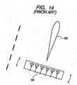
- Fig. 14 shows an example of a radar antenna 300 and a radiation beam pattern 302 generated by the antenna.
- the beam pattern is restricted finely by combining antenna elements in plurality in the lateral direction and the radiation beam is deflected right and left.
- the intensity of radar waves when emitted radar waves are returned by reflection at a target is measured, and it can be seen that the target is present in the direction of the azimuth angle with strong reception intensity.
- JP-A No.2004-239744 discloses a radar structure of a mono-pulse system, that is, having an antenna including one transmission antenna and two reception antenna (left) and reception antenna (right) disposed being opposed to each other, that is, at positions right and left to each other.
- JP-A No.2005-43375 discloses an automobile periphery monitoring device capable of efficiently tracking an object even when the number of detection points increases by widening of the angle and increasing of the sensitivity. That is, the automobile periphery monitor device of JP-A No.2005-43375 includes an object position estimation device for estimating a position to be detected at present based on an object position data in the past for each of the objects detected in the past, a window setting device of providing a predetermined window around the estimation position of the object, and an object tracking device of determining object position data at present by using detection point data contained in the window and calculating a relative velocity of the object by using object position data detected in the past.
- an object position estimation device for estimating a position to be detected at present based on an object position data in the past for each of the objects detected in the past
- a window setting device of providing a predetermined window around the estimation position of the object
- an object tracking device of determining object position data at present by using detection point data contained in the window and calculating
- JP-A No. H05-180933 discloses a method of estimating the position of a target obstacle in an automobile improved for the position estimation accuracy of a target obstacle. That is, the position estimation method of JP-A No. H05-180933 labels each obstacle data so as to affix an identical label to obstacle data close to each other on an ordinate, calculates the moving direction and the moving amount on every label based on data in the last time and the data at present, divides the moving amount by a sampling time to calculate a relative velocity on every label relative to one's own automobile, and estimates the position of the target obstacle after a predetermined time based on a relative velocity vector which is determined by the relative velocity and the moving direction.
- radar apparatus For measuring a distance to an obstacle or an automobile running in front, and an azimuth angle during running of an automobile, radar apparatus utilizing millimeter waves have been utilized generally.
- the radar apparatus emits radar waves and receives reflection waves from an object such as an obstacle or an automobile running in front. Then, it detects the intensity of received reflection waves, Doppler shift of frequency, propagation time from the emission of radar waves to the reception of reflection waves and measures a distance to the object, a relative velocity, etc. based on the result.
- constant velocity running apparatus and automobile distance control apparatus of mounting such a radar apparatus is mounted on an automobile, and detecting an obstacle or an automobile in front and conducting control operation based on the result have been put to practical use.
- JP-A No.2004-132734 involves the following two problems. At first, since the area of an antenna is enlarged for finely restricting the emission beam, it is difficult to decrease the size of an entire radar apparatus. Secondly, since a mechanical operation section is required for moving the antenna portion of a radar right and left, it is difficult to ensure long time reliability.
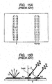
- Fig. 15A is a view showing a constitutional example of an antenna.
- Each antenna is constituted by using batch antennas.
- a transmission antenna 3 has one channel, and a reception antenna has two channels 4(a) and 4(b).
- Fig. 15B assuming the distance between the reception antennas 4(a) and 4(b) as D, two reflection signals from a target received at the reception antennas 4(a), and 4(b) have a phase difference Dsin ⁇ .
- the azimuth angle dependent intensity of a sum signal (Sum) and the azimuth angle dependent strength of a difference signal (Diff) of a power received at the two channels are as shown in Fig. 16A , and the ratio of them is calculated as shown in Fig. 16B .
- ⁇ 0 in the frontal direction of a radar, the incident angle to the right direction is positive(+), and the incident angle to the left direction is negative(-).
- the data for the azimuth angle dependence is previously measured on every radar.
- the azimuth angle( ⁇ ) of a detection target can be specified by measuring the ratio and the phase difference of the power between the sum signal and the difference signal and referring to the data for the azimuth angle dependence.
- a radar has two different radar wave reception patterns, In a case where reception antennas are combined by two channels in the lateral direction as described above, this corresponds to having two reception patterns displaced in the right and left directions and the azimuth angle position is determined by utilizing the difference of signals obtained by respective channels. Since the mono-pulse system has no mechanical operation section and has no requirement of finely restricting the radar wave emission pattern, it can be easily reduced in the size and decreased in the cost.
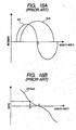
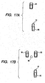
- Fig. 17A one's own automobile 80 runs while mounting a radar apparatus 81.
- An automobile 90 is a target to be measured.
- a frequency of reception signals reflected at and returned from the automobile 90 is formed as a Doppler shift frequency in accordance with the velocity difference of the two automobiles.
- the mono-pulse system has a problem in that the positions for the automobile 92 and the automobile 94 to be measured cannot be measured accurately in the situation as shown in Fig. 17B .
- the automobile periphery monitoring apparatus disclosed in JP-A No.2005-43375 has a function of estimating a position to be detected at present based on the object position data in the past, and providing a predetermined window around the estimation position for the object
- the position estimation method for a target object disclosed in JP-A No. H05-180933 calculates the moving direction and the moving amount on every label based on the data in the past and the data at present. Each of them is a method of setting the window or the label as a smoothing means for data by filtration in order to estimate the position of an object or the like to be detected at present more accurately.
- JP-A No. 2005-43375 nor JP-A No. H05-180933 discloses or suggests the presence of the problems and the means for solving them regarding the interference between two reflection signals in the situation as in Fig. 17B .
- one way a high signal-to-noise ratio and wide dynamic range imaging radar with reduced cost can be achieved is through the combination of a pulsed stepped-freaqency-continuous-wave waveform and electrically beam-switched radar architecture, utilizing a planar package containing high-frequency integrated circuits as well as integrated high-frequency waveguide coupling ports, coupled to a multi-beam waveguide-fed twist-reflector narrow beam-width antenna.
- US 2006/114146 A1 relates to a multi-targeting method for locating short-range target objects in terms of distance and angle.
- the method includes the following steps: a) a characteristic signal is emitted by a transmitting antenna of a first sensor element; b) the reflected characteristic signal is received by at least two adjacent reception antennae of the first sensor element; c) the difference in transit time of the reflected characteristic signal to the two adjacent reception antenna of the first sensor element is measured in order to determine the distance between the target objects and the first sensor element; and d) the phase differences of the characteristic signal between the two adjacent reception antenna of the first sensor element are measured in order to determine the angles between the target objects and the first sensor element.
- a device for implementing the above-mentioned method is disclosed.
- a method for processing radar signals involves coherently integrating the signals of each target track so the target (or vehicle) is divided into a number of Doppler cells, whereby an image generating mono-pulse mode is enabled. Residual errors of movement compensation are prevented with the aid of the Hilbert transformation.
- An Independent claim is also included for a radar system.
- the present invention has been accomplished for solving the problems described above and it mainly intends to solve the problems by providing a radar apparatus having signal processing means capable of accurately measuring respective azimuth angles for two targets of an identical Doppler frequency by a simple constitution, as well as a method of measuring the azimuth angle of the target even in a case where two targets having an identical Doppler shift frequency are present.
- the radar apparatus of the present invention is characterized in claims 1, whereas the method of the present invention is characterized in claim 15. Preferred embodiments of the invention are stated in the sub-daims.
- a typical example of the present invention is as shown below. That is, a radar apparatus including a transmission antenna for transmitting transmission waves to a detection region, a pair of reception antennas disposed being opposed to each other, i.e. right and left to each other, and receiving reflection waves from a target, and a signal processing circuit having a function of processing the reception signals, wherein the signal processing circuit virtually doubles the number of antennas by combining a first data obtained by the pair of reception antennas and a second data obtained at a time different from that for the first data as reception signals into a unit data set, and wherein the signal processing circuit determines the change of intensity of the reception signals based on the unit data set and measures the position for the plurality of targets.
- reception antennas 4(a), 4(b) comprising two channels as shown in Fig. 15 , by which reception signals are obtained separately.
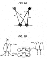
- Fig. 1A data in the past (time Ti, first data) when an identical antenna was situated in a slightly different place and data at a present position (time Ti + ⁇ T, second data), that is, data corresponding to four antenna positions 4(a), 4(b), 4(a)', 4(b)' on every slightly different time difference ⁇ T are combined respectively as a unit data set.
- reflection signals from the two targets are usually observed as a synthesis signal under the situation of Fig. 17B , individual reflection signals cannot be measured. Then, signal processing is conducted so that the reflection signals from the two targets are not synthesized.
- an azimuth angle direction in which the antenna gain decreases (hereinafter referred to as a null-point) can be generated as in the form of signal processing. Further, the low gain direction can also be scanned in the azimuth angle direction. When the low gain direction coincides with the direction of one of the targets present by the number of two, it attains a state where the reflection signal from the one target is not received and attains a state where only the reflection signal from the other target is received. That is, a state where the signal synthesis does not occur is attained. In the invention, the azimuth angle of an object is measured by detecting the state described above.
- Signals for the unit data set obtained by two reception antennas are Fourier-transformed respectively and reflection signals from the targets are detected.
- the two signals detected herein for each of the first data and the second data contained in the unit data set are complex numbers and have phase information in addition to amplitude information corresponding to a signal intensity.
- the values for the two complex numbers are to be described as S 1 , S 2 .
- a linear sum XS( ⁇ ) is calculated in accordance with the following formula (formula 1) while rotating the phase by ⁇ for the complex number value S 1 :
- XS ⁇ S 1 ⁇ e j ⁇ - S 2
- an azimuth angle direction of low antenna gain is generated as in the form of signal processing by calculating a linear sum for both of them while rotating the phase of one of the two reception signals obtained by the reception antennas present by the number of two.
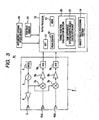
- the schematic view for the azimuth angle gain characteristic of the reception antenna constituted by conducting the calculation is as shown by a curve 60-1 (corresponding to the first data), and a curve 60-2 (corresponding to the second data) in Fig. 2B .
- the curve 60-1 in Fig. 2B shows a state where the gain is low in the direction of the azimuth angle ⁇ and the reflection waves from the direction are scarcely received.
- Calculation of XS( ⁇ ) relative to the phase rotation angle ⁇ of various values in formula 1 corresponds to change of the low gain direction to various directions in Fig 2B . Accordingly, calculation of XS( ⁇ ) while intentionally rotating the phase rotation angle ⁇ is identical with scanning of the low gain direction in the azimuth angle direction.
- the position for an object to be detected is measured by using two sets of data obtained at two slightly different times (Ti, Ti+ ⁇ T) as a unit data set by an identical antenna mounted on a radar apparatus.
- the azimuth angle of the detected object is measured by using two sets of data including data of XS( ⁇ ) obtained at the antenna position (4(a), 4(b)) at present (time Ti), and the data of XS( ⁇ ) obtained at the antenna position (4(a)', 4(b)') slightly different from the present position (time Ti+ ⁇ T) of the automobile.
- signal processing capable of obtaining the effect equivalent with that of virtually increasing the number of antennas to four (4(a), (b), 4(a)', 4(b)') can be conducted.
- a minute time distance for obtaining the first data and the second data that is, a slightly different time difference ⁇ T is changed in accordance with the moving velocity of the radar apparatus, that is, the running velocity of an automobile mounting the radar apparatus and the yaw rate of the automobile as shown in Fig. 1B .
- ⁇ T is given as a function in which ⁇ Tv decreases along with increase of the running velocity of the one's own automobile, and also given by a function in which ⁇ Ty decreases along with increase of the curvature of a road.
- the signal intensity compared before and after the fine movement of the antenna is a signal intensity calculated by a predetermined calculation from two channels in a case where the low gain direction is scanned in various directions.
- the signal intensity described above scarcely changes only by the fine movement of the radar. Accordingly, it can be seen that the target is present at the azimuth angle along which the low gain direction is directed when the signal intensity becomes identical before and after the movement of the antenna.
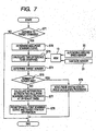
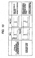
- a radar apparatus 81 includes an analog circuit 1 having a signal generation function, a transmission function, and a reception function, and a signal processing circuit (digital processor) 10 having a function of processing reception signals. That is, the analog circuit 1 has a modulator 2, an oscillator 5, a power amplifier 6, and a transmission antenna 3 in the transmission system, and reception antennas 4(a), 4(b), mixer circuits 7(a), 7(b), power amplifiers 8(a), 8(b), and A/D converters 9(a), 9(b) in the reception system.
- the signal outputted from the A/D converter 9 is processed in the signal processing circuit 10 to determine at least one of the distance to a target or the relative velocity.
- the signal processing circuit 10 includes a CPU, a memory, and a data processor for holding programs and has a Fast Fourier Transformation (FFT) processing section 11, a peak search processing section 12, a memory 13, a target position calculation section 20, and an object tracing processing section 14.
- the target position calculation section 20 has a time difference system azimuth angle calculation unit 21. Further, an output from the automobile ground speed sensor 30 and a yaw rate sensor 31 are also inputted to the signal processing circuit 10 and they are recorded and held in the memory 13.
- FFT Fast Fourier Transformation
- Each of the sections described above of the signal processing circuit 10 has a function attained by execution of the calculation processing based on various programs in the CPU. It will be apparent that the specific constitution of the signal processing circuit 10 may also be attained by integrating a portion of the function for each of the sections in combination or further dividing the portion.
- the information obtained by the object tracing processing section 14 is sent to an external ACC (Adaptive Cruise Control) device by way of a serial communication device, etc. to conduct running control for the automobile.
- ACC Adaptive Cruise Control
- Fig. 4 shows a more specific constitutional example of the target position calculation section 20.
- the target position calculation section 20 has, in addition to the time difference system azimuth angle calculation unit 21, a mono-pulse system azimuth angle calculation unit 22, a relative velocity calculation unit 23, a distance calculation unit 24, a time difference setting unit 25, and a target number judging unit 26.
- the time difference system azimuth angle calculation unit 21 has a null-point scanning curve calculation section 211, a curve comparison section 212, and a null-point scanning curve memory section 213.
- the null-point scanning curve calculation section 211 has a function of calculating null-point scanning curves (curve 110, 120 in Fig. 11 ) to be described later.
- the null-point scanning curve comparison section 212 has a function of determining an intersection between two null-point scanning curves, that is, an azimuth angle of the target. The information regarding the null-point is held in the null-point scanning curve memory section 213.
- the relative velocity and the distance of respective targets are calculated, for example, based on the principle of a 2 frequency CW system.
- the function of the null-point scanning curve calculation section 211 and the curve comparison section 212 of the time difference system azimuth angle calculation unit 21 is to be described later.
- the target number judging unit 26 judges the number of targets from the processed data of the reflection signal and conducts judging processing in that the processing for the calculation of the azimuth angle should be conducted by the time difference system azimuth angle calculation unit 21 or by the mono-pulse system azimuth angle calculation unit 22.
- Each of the azimuth angle calculation units 21, 22 calculates the azimuth angle. That is, even in a case where two targets of an identical Doppler frequency are present in the reflection signal, the time difference azimuth angle calculation unit 21 calculates respective azimuth angles based on the time difference system described with reference to Fig. 1A . On the other hand, in a case where the target is present by the number of 1, the azimuth angle is calculated by the mono-pulse system azimuth angle calculation unit 22.
- the constitution of the target position calculation section 20 may also be attained by combining and integrating a portion of the function of each of the units or each of the sections described above, or further dividing a portion of them.
- the oscillator 5 in the analog circuit 1 oscillates at a frequency pattern, for example, as shown in Fig. 6A based on the modulation signal from the modulator 2.
- This is the frequency modulation system referred to as a 2 frequency CW system but, instead, other systems, for example, an FMCW type modulation system or the like may also be used.
- the frequency modulated high frequency signal is amplified by the power amplifier 6 and then emitted from the transmission antenna 3 as transmission waves to the detection region.
- the radar waves transmitted from the transmission antenna 3 are reflected at an object (target) in the emission region and the returned radar wave is received by the reception antenna 4.
- a beat signal is generated, and the beat signal is outputted to the power amplifier 8.
- the signal amplified by and outputted from the power amplifier 8 is converted by the A/D converter 9 into a digital signal and then sent to the signal processing circuit 10.
- a predetermined calculation is conducted to the reception signal in accordance with a flow chart shown in Fig. 5 .
- frequency analysis is conducted by Fast Fourier Transformation (FFT) at step 41 to obtain a frequency spectrum.
- FFT Fast Fourier Transformation
- S/N signal-to-noise power ratio
- the thus observed peak is extracted by peak search in the next step 42.
- a position information calculation processing of the target is applied at step 43.
- the processing at step 43 is executed by the position calculation section 20.
- the relative velocity calculation unit 23 and the distance calculation unit 24 in the target position calculation section 20 calculate the relative velocity and the distance of the targets respectively based, for example, on the 2 frequency CW system principle.
- the two target positions are measured by using the unit data set at step 43 in Fig. 5 and, by utilizing the result, tracking processing is applied respectively at step 44.
- the amending means a Kalman filter or an ⁇ filter used so far in the field of the radar technique is utilized.
- XS( ⁇ ) takes an identical value for all azimuth angles at time Ti and Time Ti+ ⁇ T. This is because only the signal for one target is received and no interference is caused irrespective of the low gain direction.
- the azimuth angle of the target is determined in this case, for example, in accordance with usual mono-pulse system. That is, the azimuth angle of the target is determined by the mono-pulse system azimuth angle calculation unit 22 in Fig. 4 in the manner as described for Figs. 16A, 16B , 17A and 17B . Then, tracking processing is applied in the step 44.
- a unit data set is obtained by utilizing the movement for the position of an automobile-mounted radar during slight time difference ⁇ T and the number of antennas is virtually increased along with the moving direction of the radar.
- change of distance between the one's own automobile and the target at a slight time difference ⁇ T is utilized for detecting the change of a relative positional relation between the automobile-mounted radar and the target.
- Fig. 7 it is judged at step 71 whether the distance between the radar and the target coincides with the value measured at the last time or not.
- the azimuth angle measuring method of the invention can be used. Then, it goes to the step 72 and a null-point scanning curve is determined.
- the null-point scanning curve is to be described specifically later with reference to Fig. 11 .
- step 73 it is decided to compare the null-point scanning curve with which null-point scanning curve determined and stored in the past, that is, to compare one set of null-point scanning curves with which value for a slight time difference ⁇ T between them, based on the output information from the automobile velocity sensor and the yaw rate sensor.
- the number of targets is determined by the two null-point scanning curves.
- the value for XS( ⁇ ) has an identical value for all azimuth angles at time Ti and time Ti+ ⁇ T.
- the azimuth angle of the target is determined in accordance with a usual mono-pulse system (step 75, 76).
- intersections between two null-point scanning curves (curves 110, 120 in Fig. 11 ), that is, azimuth angles ⁇ A , ⁇ B for the targets are determined.
- step 78 the null-point scanning curve determined at present and the target position information are registered in a storage device such as a memory.
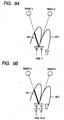
- Fig. 8A shows a state where the direction of the azimuth angle of low antenna gain obtained by conducting predetermined calculation to the unit data set, that is, reception signals of the two reception antennas coincides with the direction of one of the two targets. That is, Fig. 8A shows a case where the phase rotational angle ⁇ in the (formula 1) coincides with one of the two targets.
- a target A and a target B are present and the phase rotational angle ⁇ coincides with the azimuth angle ⁇ B of the target B.
- the reflection signal from the target B is not received and only the reflection signal from the target A is received. That is, even in a case where targets of an identical Doppler frequency are present by the number of two, a state in which reflection signals from both of them are not synthesized is generated.
- Fig. 8B shows a situation in which the azimuth angle of low antenna gain generated by conducting predetermined calculation to the reception signals of the two reception antennas coincides with none of the two targets.
- the low gain direction does not coincide with the direction of the target, reflection signals from the two targets are synthesized.
- the state is expressed also as that in which two reflection signals interfere with each other.
- the azimuth angle of the target is determined by the following method.
- the phase rotational angle ⁇ of XS( ⁇ ) represented by the formula 1 is calculated while changing the phase rotational angle ⁇ within the range of the detection angle, for example, at a step of 0.1 degree. Then, when an absolute value of XS( ⁇ ) is drawn as a function of the phase rotational angle ⁇ , it generates a null-point scanning curve 110, for example, as shown in Fig. 11 . In the invention, the thus generated curve is defined as a null-point scanning curve. The time at this point is defined as Ti.
- a null-point scanning curve 120 is generated, for example, as shown in Fig. 11 .
- the time apart by a slight time ⁇ T may be, for example, a fixed value of about several tens of a sec, or it may be changed in accordance with the information of the running state of the one's own automobile obtained from the automobile velocity sensor 30 or the yaw rate sensor 31 with the initial value of about several tens of a sec as a reference.
- phase rotational angles ⁇ at the intersections between the two null-point scanning curves 110 and 120 form azimuth angle positions ⁇ A , ⁇ B of the targets.
- the state in Fig. 8A is a state where only the reflection signal from the target A is received.
- the signal intensity scarcely changes only by the subsequent fine movement of the radar. That is, the absolute value of XS( ⁇ A ) takes a substantially identical value at time Ti and Ti+ ⁇ T.
- This can be interpreted as below with reference to Fig. 9A and Fig. 9B .
- the intensity of the reflection waves from the target A is represented by the length L1 of a thick line 100 in Fig. 9A .
- the intensity of the reflection waves from the target A is represented by a thick line 101 in Fig. 9B in the same manner.
- Ti+ ⁇ T-Ti it can be considered that the length L2 for the thick line 100 and the thick line 101 is identical.
- phase rotational angle ⁇ is an azimuth angle different from that for the target position
- the reflection signals from the two targets interfere to each other
- the position of the radar moves with lapse of time to change the positional relation with the targets
- the way of synthesizing the reflection signals for both of them is different.
- the intensity of the synthesis signal generally fluctuates greatly and XS( ⁇ ) takes different values between time Ti and Ti+ ⁇ T (L1 ⁇ L2).
- the azimuth angle positions ⁇ A , ⁇ B for the target A and the target B are determined by determining the positions for the intersections between the two null-point scanning curves 110 and 120.
- the slightly different time difference ⁇ T may be set property as a time distance suitable for obtaining an appropriate number of data when the low gain direction is directed to one of the targets, the reflection signal XS( ⁇ B ) from the other of the targets is detected as a substantially identical state.
- Fig. 13A and Fig. 13B show an example of the result of an experiment that conducts processing for detecting the target position by mounting a radar apparatus according to the embodiment of the invention and a radar apparatus according to the existent mono-pulse system respectively on automobiles.
- Fig. 13A shows the result of an embodiment of the invention and Fig. 13B shows that by an existent mono-pulse system.
- the reception antenna of the radar apparatus comprises 2 channels and two targets are positioned in a detection region in front of the one's own automobile (like the scene as in Fig. 12 ), and the velocity of the one's own automobile is higher than the velocity of the two targets running in front.
- two targets can be distinguished distinctly on the side of the distance nearer to the distance where the angle between the two targets is equal with the minimum separable angle.
- it is detected as if one target staggers as shown in (B). This is because reflection signals from the two targets interfere to each other.
- a radar apparatus having a signal processing device capable of measuring the respective azimuth angles of the two targets, even when two targets of an identical Doppler shift frequency are present, by a simple constitution, for example, by adding a function of time difference system azimuth angle calculation to the hardware structure of the radar apparatus adopting a mono-pulse system.
- the azimuth angle of a target moving relatively to the radar apparatus can be measured by using the signal processing described above in the signal processing circuit 10 having a time difference system azimuth angle calculation unit 21, etc. to such a target. That is, in a radar apparatus for detecting an object by emitting radar waves and processing reflection waves thereof, respective azimuth angles of two targets can be measured by using measured data obtained at present by an antenna mounted to the radar apparatus and measured data obtained for a relative positional relation between the target and the antenna at a time which is different by slight time ⁇ T from the current time as a unit data set and calculating the azimuth angle according to the time difference system.
- the radar apparatus of the invention is used being mounted on the automobile
- the application use is not restricted to that for the automobile.
- it can also be used as an apparatus which is mounted to an air craft or a ship, monitors an obstacle, and conducts running control or warning.
Claims (12)
- Radarvorrichtung mit einer Übertragungsantenne (3) zur Übertragung von
Übertragungswellen an eine Messregion, wobei ein Paar von Empfangsantennen (4a, 4b) an Positionen rechts und links voneinander angeordnet sind und reflektierte Wellen von Zielobjekten empfangen, und eine Signalverarbeitungsschaltung (10) die eine Funktion hat,
die Empfangssignale, die an den Empfangsantennen erhalten werden, zu verarbeiten,
wobei die Signalverarbeitungsschaltung (10) virtuell die Anzahl der Antennen (4a, 4b) dadurch verdoppelt, dass erste Daten, die von dem Paar der Empfangsantennen empfangen werden,
und zweite Daten, die an einem Zeitpunkt unterschiedlich von dem für die ersten Dateien erhalten werden, als Empfangssignale in einen einheitlichen Datensatz kombiniert werden,
und
wobei die Signalverarbeitungsschaltung (10) die Änderung der Intensität der Empfangssignale auf der Basis des einheitlichen Datensatzes bestimmt und die Position für die Vielzahl der Zielobjekte misst,
gekennzeichnet durch
eine Einrichtung zur Berechnung einer linearen Summe für zwei Empfangssignale, die von dem Paar der Empfangsantennen erhalten werden, während die Phase von einer derselben gedreht wird, so dass die Richtung eines Azimutwinkels bei geringem
Antennenverstärkungsgrad (60-1) wie in der Form der Signalverarbeitung erzeugt wird; und
eine Einrichtung zum Abtasten der Richtung des Azimutwinkels mit niedrigem Antennenverstärkungsgrad und zur Beurteilung und Abgabe eines Rotationswinkels der Phase, wo die Intensität (100) des Empfangssignals gemessen an der vorgegebenen Zeit Ti identisch mit der Intensität (101) des Empfangssignals berechnet aus den Daten ist, die an einem Zeitpunkt, der um eine Zeit ΔT unterschiedlich von dem Zeitpunkt Ti ist, erhalten wurden als existierender Winkel des Zielobjekts; wobei
die Positionsbeziehung zwischen dem Zielobjekt und der Radarvorrichtung (81) sich mit Ablauf der Zeit ändert. - Radarvorrichtung nach Anspruch 1, worin die zu messende Position für die Vielzahl der Zielobjekte ein Azimutwinkel für jedes der Zielobjekte ist.
- Radarvorrichtung nach Anspruch 1, worin die Signalverarbeitungsschaltung (10) ferner aufweist:eine Einrichtung zur Fourier-Transformation der Signale, die von dem Paar der Empfangsantennen respektive erhalten werden, und zur Bestimmung eines reflektierten Signals von dem Zielobjekt;eine Einrichtung zur Berechnung einer linearen Summe XS(θ) entsprechend der folgenden Formel unter der Annahme, dass die gemessenen zwei reflektierten Signale jeweils eine komplexe Zahl als S1 und S2 aufweisen
 undeine Einrichtung zur Erzeugung der Richtung eines Azimutwinkels des niedrigen Antennen-Verstärkungsgrads durch eine Berechnung der linearen Summe für beide derselben.
 - Radarvorrichtung nach Anspruch 3, worin die Signalverarbeitungsschaltung (10) ferner aufweist:eine Einrichtung zur Entwicklung eines Zustandes, bei dem der Phasen-Rotationswinkel θ in der Formel, wie sie in Anspruch 3 definiert ist, mit einem der Zielobjekte , die in der Anzahl von zwei vorhanden sind, zusammenfällt, wodurch ein Zustand erzeugt wird bei dem reflektierte Signale von den beiden Zielobjekten mit einer identischen Doppler-Verschiebungsfrequenz nicht synchronisiert werden in einem Fall, wo diese zwei Zielobjekte wie in der Form der Signalverarbeitung vorhanden sind.
- Radarvorrichtung nach Anspruch 3, worin die Phase um θ für die komplexe Zahl S1 gedreht wird.
- Radarvorrichtung nach Anspruch 5, worin die Signalverarbeitungsschaltung (10) einen Zustand entwickelt, bei dem der Phasen-Rotationswinkel θ in der Formel, wie sie in Anspruch 3 definiert ist, mit einem der Zielobjekte zusammenfällt, die in der Anzahl von zwei vorhanden sind, wodurch ein Zustand erzeugt wird, bei dem die reflektierten Signale von den zweit Zielobjekten mit einer identischen Dopplerverschiebungs-Frequenz nicht synchronisiert werden wie in der Form der Signalverarbeitung in dem Fall, wo diese zwei Zielobjekte vorhanden sind.
- Radarvorrichtung nach Anspruch 1, wobei die Zeitdifferenz ΔT für die unterschiedliche Zeit,
die in dem einheitlichen Datensatz verwendet wird, entsprechend der
Bewegungsgeschwindigkeit der Radarvorrichtung geändert wird. - Radarvorrichtung nach Anspruch 1, worin die Radarvorrichtung mit Ablauf der Zeit sich weiter bewegt.
- Radarvorrichtung nach Anspruch 1,
worin die Radarvorrichtung auf einem Automobil montiert ist, und
wobei die Zeitdifferenz ΔT der unterschiedlichen Zeit, die für den einheitlichen Datensatz verwendet wird, entsprechend der Fahrgeschwindigkeit des Automobils, auf dem die Radarvorrichtung montiert ist, und der Gierrate des Automobils geändert wird. - Radarvorrichtung nach Anspruch 1,
wobei die Radarvorrichtung sich an einer stationären Position befindet, und
wobei die Signalverarbeitungsschaltung (10) eine Einrichtung zum Messen des Azimutwinkels des Zielobjekts unter Verwendung der Messdaten aufweist, die gegenwärtig erhalten werden,
und den Messdaten, die in der Vergangenheit bei dem Zeitpunkt ΔT erhalten wurden, bei dem die Positionsbeziehung zwischen dem Zielobjekt und der Antenne der Radarvorrichtung sich von der Positionsbeziehung an dem gegenwärtigen Zeitpunkt unterscheidet. - Radarvorrichtung nach Anspruch 1, umfassend eine Analogschaltung (1), die eine Generatorfunktion, eine Sendefunktion und eine Empfangsfunktion für Signale hat, und eine Signalverarbeitungsschaltung (10), die eine Verarbeitungsfunktion der Empfangssignale hat,
wobei die Analogschaltung (1) eine Sendeantenne zur Übertragung von Sendewellen an eine Messregion und ein Paar von Empfangsantennen aufweist, die an Positionen rechts und links voneinander angeordnet sind;
wobei die Signalverarbeitungsschaltung (10) die reflektierte Welle der empfangenen Übertragungswellen als ein Empfangssignal verarbeitet und das Zielobjekt verfolgt. - Verfahren zur Messung eines Azimutwinkels eines Zielobjekts in einer Radarvorrichtung (81) umfassend eine Sendeantenne (3) und ein Paar von Empfangsantennen (4a, 4b), die an Positionen rechts und links voneinander angeordnet sind, und eine Signalverarbeitungsschaltung (10) mit einer Einrichtung zur Verarbeitung von Empfangssignalen, die an den Empfangsantennen erhalten werden, wobei das Verfahren die folgenden Schritte aufweist:Übertragung von Sendewellen von der einen Sendeantenne an eine Empfangsregion; Empfangen der reflektierten Wellen der Sendewellen durch ein Paar von Empfangsantennen, die an Positionen rechts und links voneinander angeordnet sind;Kombinieren von ersten Daten, die von dem Paar der Empfangsantennen empfangen werden, und von zweiten Daten, die an einer unterschiedlichen Zeit von den ersten Daten als einheitlicher Datensatz von Empfangssignalen empfangen werden;Bestimmen der Änderung der Intensität der Empfangssignale von dem einheitlichen Datensatz und Messen der Position des Azimutwinkels für eine Vielzahl von Zielobjekten, gekennzeichnet durchBerechnen einer linearen Summe für zwei Empfangssignale, die von dem Paar der Empfangsantennen erhalten werden, während die Phase von einer derselben gedreht wird, so dass die Richtung eines Azimutwinkels bei niedrigem Antennenverstärkungsgrad (60-1) wie in der Form der Signalverarbeitung; undAbtasten der Richtung des Azimutwinkels mit niedrigem Antennenverstärkungsgrad und Beurteilen und Abgeben eines Rotationswinkels der Phase, wo die Intensität (100) des Empfangssignals gemessen an der vorgegebenen Zeit Ti identisch mit der Intensität (101) des Empfangssignals berechnet aus den Daten ist, die an einem Zeitpunkt, der um eine Zeit ΔT unterschiedlich von dem Zeitpunkt Ti ist, erhalten wurden als existierender Winkel des Zielobjekts; wobeidie Positionsbeziehung zwischen dem Zielobjekt und der Radarvorrichtung sich mit Ablauf der Zeit ändert
Applications Claiming Priority (1)
| Application Number | Priority Date | Filing Date | Title |
|---|---|---|---|
| JP2007323068A JP5091651B2 (ja) | 2007-12-14 | 2007-12-14 | レーダ装置及びターゲットの方位角計測方法 |
Publications (2)
| Publication Number | Publication Date |
|---|---|
| EP2071357A1 EP2071357A1 (de) | 2009-06-17 |
| EP2071357B1 true EP2071357B1 (de) | 2011-04-06 |
Family
ID=40427887
Family Applications (1)
| Application Number | Title | Priority Date | Filing Date |
|---|---|---|---|
| EP08171208A Expired - Fee Related EP2071357B1 (de) | 2007-12-14 | 2008-12-10 | Radarvorrichtung und Verfahren zur Messung des Azimutwinkels des Ziels |
Country Status (4)
| Country | Link |
|---|---|
| US (1) | US7760134B2 (de) |
| EP (1) | EP2071357B1 (de) |
| JP (1) | JP5091651B2 (de) |
| DE (1) | DE602008005998D1 (de) |
Families Citing this family (18)
| Publication number | Priority date | Publication date | Assignee | Title |
|---|---|---|---|---|
| JP5501578B2 (ja) * | 2008-06-30 | 2014-05-21 | 三菱電機株式会社 | レーダ装置 |
| JP5093298B2 (ja) * | 2010-06-04 | 2012-12-12 | 株式会社デンソー | 方位検出装置 |
| JP5653726B2 (ja) * | 2010-11-12 | 2015-01-14 | 株式会社デンソー | レーダ装置 |
| US20120126829A1 (en) * | 2010-11-22 | 2012-05-24 | Boris Leonid Sheikman | Methods and systems for monitoring components using a microwave emitter |
| US8854052B2 (en) * | 2010-11-22 | 2014-10-07 | General Electric Company | Sensor assembly and method of measuring the proximity of a machine component to a sensor |
| KR101207890B1 (ko) | 2011-02-01 | 2012-12-04 | 재단법인대구경북과학기술원 | 차량용 펄스 레이다의 다중 이동 타겟의 각도 탐지장치 및 방법 |
| TWI448715B (zh) | 2012-07-30 | 2014-08-11 | Univ Nat Chiao Tung | 移動參數估計方法、角度估計方法及判斷方法 |
| TWI470257B (zh) | 2013-10-07 | 2015-01-21 | Univ Nat Chiao Tung | 角度估計檢測方法及電子裝置 |
| JP6365251B2 (ja) * | 2014-02-28 | 2018-08-01 | パナソニック株式会社 | レーダ装置 |
| KR102435550B1 (ko) * | 2015-06-09 | 2022-08-24 | 주식회사 에이치엘클레무브 | 레이더 신호처리 장치 및 그 신호처리방법 |
| RU2631118C1 (ru) * | 2016-10-24 | 2017-09-19 | Акционерное общество "Государственный Рязанский приборный завод" | Способ определения азимута цели с помощью интерполированной пеленгационной характеристики |
| US11726822B2 (en) | 2017-06-05 | 2023-08-15 | Umajin Inc. | Systems and methods for providing digital twin-enabled applications |
| US20200285977A1 (en) * | 2017-06-05 | 2020-09-10 | Umajin Inc. | Asset tracking system and methods |
| US11922564B2 (en) | 2017-06-05 | 2024-03-05 | Umajin Inc. | Generative content system that supports location-based services and methods therefor |
| US11092686B2 (en) * | 2018-09-19 | 2021-08-17 | Steradian Semiconductors Private Limited | Method, apparatus and device for doppler compensation in a time switched MIMO radar system |
| KR102206223B1 (ko) | 2018-10-08 | 2021-01-22 | 주식회사 만도 | 데이터 처리 방법, 데이터 처리 장치 및 차량 제어 시스템 |
| WO2020157924A1 (ja) * | 2019-01-31 | 2020-08-06 | 三菱電機株式会社 | 測角装置、測角方法及び車載装置 |
| CN110940957B (zh) * | 2019-10-28 | 2022-03-22 | 惠州市德赛西威汽车电子股份有限公司 | 一种模块化毫米波雷达 |
Family Cites Families (15)
| Publication number | Priority date | Publication date | Assignee | Title |
|---|---|---|---|---|
| US2991463A (en) * | 1956-05-28 | 1961-07-04 | Thompson Ramo Wooldridge Inc | Collision indication system |
| JP3016047B2 (ja) | 1991-12-27 | 2000-03-06 | 本田技研工業株式会社 | 車両における対照障害物の位置推定方法 |
| JP3491418B2 (ja) * | 1995-12-01 | 2004-01-26 | 株式会社デンソー | Fmcwレーダ装置 |
| JPH11125672A (ja) * | 1997-10-24 | 1999-05-11 | Mitsubishi Electric Corp | Fm−cwレーダ |
| JPH11133143A (ja) * | 1997-10-31 | 1999-05-21 | Toyota Motor Corp | レーダ装置 |
| DE19912370A1 (de) * | 1998-05-02 | 1999-12-16 | Daimlerchrysler Aerospace Ag | Verfahren zur Radarsignalverarbeitung und Radaranordnung insbesondere in einem Kraftfahrzeug |
| JP3829659B2 (ja) * | 2001-07-02 | 2006-10-04 | 三菱電機株式会社 | レーダ装置 |
| JP4079739B2 (ja) | 2002-10-08 | 2008-04-23 | 富士通テン株式会社 | 車載用レーダ装置 |
| US7224717B1 (en) * | 2002-11-15 | 2007-05-29 | Lockheed Martin Corporation | System and method for cross correlation receiver |
| DE10258367A1 (de) * | 2002-12-12 | 2004-07-08 | Daimlerchrysler Ag | Mehrzielfähiges Verfahren und mehrzielfähige Sensorvorrichtung für die Abstands- und Winkelortung von Zielobjekten im Nahbereich |
| JP2004239744A (ja) | 2003-02-06 | 2004-08-26 | Hitachi Ltd | レーダ装置 |
| JP4093109B2 (ja) * | 2003-05-15 | 2008-06-04 | 株式会社デンソー | 車両用レーダ装置 |
| EP1761799A2 (de) * | 2004-04-12 | 2007-03-14 | Ghz Tr Corporation | Verfahren und vorrichtungen für fahrzeugradarsensoren |
| JP2006047114A (ja) * | 2004-08-04 | 2006-02-16 | Fujitsu Ten Ltd | レーダ装置 |
| JP3954053B2 (ja) | 2004-09-03 | 2007-08-08 | 三菱電機株式会社 | 車両周辺監視装置 |
-
2007
- 2007-12-14 JP JP2007323068A patent/JP5091651B2/ja active Active
-
2008
- 2008-12-10 EP EP08171208A patent/EP2071357B1/de not_active Expired - Fee Related
- 2008-12-10 DE DE602008005998T patent/DE602008005998D1/de active Active
- 2008-12-12 US US12/314,578 patent/US7760134B2/en active Active
Also Published As
| Publication number | Publication date |
|---|---|
| EP2071357A1 (de) | 2009-06-17 |
| DE602008005998D1 (de) | 2011-05-19 |
| JP2009145206A (ja) | 2009-07-02 |
| US20090153395A1 (en) | 2009-06-18 |
| JP5091651B2 (ja) | 2012-12-05 |
| US7760134B2 (en) | 2010-07-20 |
Similar Documents
| Publication | Publication Date | Title |
|---|---|---|
| EP2071357B1 (de) | Radarvorrichtung und Verfahren zur Messung des Azimutwinkels des Ziels | |
| US11747435B2 (en) | Techniques for angle resolution in radar | |
| US7924215B2 (en) | Radar apparatus and mobile object | |
| US9746554B2 (en) | Radar imaging system and related techniques | |
| EP1467223B1 (de) | Radareinrichtung | |
| EP1074853B1 (de) | Fahrzeug-Radargerät | |
| US20070008211A1 (en) | Vehicle mounted radar apparatus | |
| JP2011127910A (ja) | レーダ装置及びレーダシステム | |
| JP2009041981A (ja) | 物体検出装置および方法、ならびに物体検出装置を備えた車両 | |
| US20230204713A1 (en) | Radar System with Modified Orthogonal Linear Antenna Subarrays | |
| US20150061923A1 (en) | Phase monopulse radar system and target detecting method | |
| EP3985414A1 (de) | Radarsystem mit einem ausgedünnten primärarray und einem dichten hilfsarray | |
| WO2018181743A1 (ja) | 車載レーダ装置 | |
| US6943727B2 (en) | Length measurement with radar | |
| US11709261B2 (en) | Radar device for vehicle, controlling method of radar device and radar system for vehicle | |
| US6369748B1 (en) | Radar system mounted on vehicle | |
| JP4863679B2 (ja) | 位置測定装置 | |
| US11681039B2 (en) | Failure determination apparatus and method of vehicle radar apparatus, and vehicle radar apparatus with the same | |
| US11802960B2 (en) | Phase correcting apparatus and method of transmission signal of vehicle radar, and vehicle radar apparatus with the same | |
| US11150338B2 (en) | Azimuth calculation device and azimuth calculation method | |
| JP2021073452A (ja) | 電子機器、電子機器の制御方法、及び電子機器の制御プログラム | |
| US11921230B2 (en) | Radar device and signal processing method | |
| US20240036183A1 (en) | Radar method and radar system for a phase-coherent analysis | |
| JP4432967B2 (ja) | レーダ信号処理装置 | |
| CN114514440A (zh) | 电子设备、电子设备的控制方法、以及电子设备的控制程序 |
Legal Events
| Date | Code | Title | Description |
|---|---|---|---|
| PUAI | Public reference made under article 153(3) epc to a published international application that has entered the european phase |
Free format text: ORIGINAL CODE: 0009012 |
|
| 17P | Request for examination filed |
Effective date: 20081218 |
|
| AK | Designated contracting states |
Kind code of ref document: A1 Designated state(s): AT BE BG CH CY CZ DE DK EE ES FI FR GB GR HR HU IE IS IT LI LT LU LV MC MT NL NO PL PT RO SE SI SK TR |
|
| AX | Request for extension of the european patent |
Extension state: AL BA MK RS |
|
| RIN1 | Information on inventor provided before grant (corrected) |
Inventor name: MITOMA, HIROTOC/O HITACHI LTD. Inventor name: MORINAGA, MITSUTOSHIC/O HITACHI LTD. |
|
| 17Q | First examination report despatched |
Effective date: 20091021 |
|
| AKX | Designation fees paid |
Designated state(s): DE FR |
|
| GRAP | Despatch of communication of intention to grant a patent |
Free format text: ORIGINAL CODE: EPIDOSNIGR1 |
|
| GRAS | Grant fee paid |
Free format text: ORIGINAL CODE: EPIDOSNIGR3 |
|
| GRAA | (expected) grant |
Free format text: ORIGINAL CODE: 0009210 |
|
| AK | Designated contracting states |
Kind code of ref document: B1 Designated state(s): DE FR |
|
| REF | Corresponds to: |
Ref document number: 602008005998 Country of ref document: DE Date of ref document: 20110519 Kind code of ref document: P |
|
| REG | Reference to a national code |
Ref country code: DE Ref legal event code: R096 Ref document number: 602008005998 Country of ref document: DE Effective date: 20110519 |
|
| PLBE | No opposition filed within time limit |
Free format text: ORIGINAL CODE: 0009261 |
|
| STAA | Information on the status of an ep patent application or granted ep patent |
Free format text: STATUS: NO OPPOSITION FILED WITHIN TIME LIMIT |
|
| 26N | No opposition filed |
Effective date: 20120110 |
|
| REG | Reference to a national code |
Ref country code: DE Ref legal event code: R097 Ref document number: 602008005998 Country of ref document: DE Effective date: 20120110 |
|
| PGFP | Annual fee paid to national office [announced via postgrant information from national office to epo] |
Ref country code: FR Payment date: 20130107 Year of fee payment: 5 |
|
| REG | Reference to a national code |
Ref country code: FR Ref legal event code: ST Effective date: 20140829 |
|
| PG25 | Lapsed in a contracting state [announced via postgrant information from national office to epo] |
Ref country code: FR Free format text: LAPSE BECAUSE OF NON-PAYMENT OF DUE FEES Effective date: 20131231 |
|
| PGFP | Annual fee paid to national office [announced via postgrant information from national office to epo] |
Ref country code: DE Payment date: 20141202 Year of fee payment: 7 |
|
| REG | Reference to a national code |
Ref country code: DE Ref legal event code: R119 Ref document number: 602008005998 Country of ref document: DE |
|
| PG25 | Lapsed in a contracting state [announced via postgrant information from national office to epo] |
Ref country code: DE Free format text: LAPSE BECAUSE OF NON-PAYMENT OF DUE FEES Effective date: 20160701 |