EP2070102B1 - Mehrfachprobenquellen zur verwendung mit massenspektrometern und vorrichtungen, einrichtungen und verfahren dafür - Google Patents
Mehrfachprobenquellen zur verwendung mit massenspektrometern und vorrichtungen, einrichtungen und verfahren dafür Download PDFInfo
- Publication number
- EP2070102B1 EP2070102B1 EP07815905.0A EP07815905A EP2070102B1 EP 2070102 B1 EP2070102 B1 EP 2070102B1 EP 07815905 A EP07815905 A EP 07815905A EP 2070102 B1 EP2070102 B1 EP 2070102B1
- Authority
- EP
- European Patent Office
- Prior art keywords
- sample
- samples
- chamber
- source
- ions
- Prior art date
- Legal status (The legal status is an assumption and is not a legal conclusion. Google has not performed a legal analysis and makes no representation as to the accuracy of the status listed.)
- Active
Links
Images





Classifications
-
- H—ELECTRICITY
- H01—ELECTRIC ELEMENTS
- H01J—ELECTRIC DISCHARGE TUBES OR DISCHARGE LAMPS
- H01J49/00—Particle spectrometers or separator tubes
- H01J49/02—Details
- H01J49/10—Ion sources; Ion guns
- H01J49/107—Arrangements for using several ion sources
-
- H—ELECTRICITY
- H01—ELECTRIC ELEMENTS
- H01J—ELECTRIC DISCHARGE TUBES OR DISCHARGE LAMPS
- H01J49/00—Particle spectrometers or separator tubes
- H01J49/0009—Calibration of the apparatus
-
- H—ELECTRICITY
- H01—ELECTRIC ELEMENTS
- H01J—ELECTRIC DISCHARGE TUBES OR DISCHARGE LAMPS
- H01J49/00—Particle spectrometers or separator tubes
- H01J49/0095—Particular arrangements for generating, introducing or analyzing both positive and negative analyte ions
-
- H—ELECTRICITY
- H01—ELECTRIC ELEMENTS
- H01J—ELECTRIC DISCHARGE TUBES OR DISCHARGE LAMPS
- H01J49/00—Particle spectrometers or separator tubes
- H01J49/02—Details
- H01J49/06—Electron- or ion-optical arrangements
- H01J49/067—Ion lenses, apertures, skimmers
-
- H—ELECTRICITY
- H01—ELECTRIC ELEMENTS
- H01J—ELECTRIC DISCHARGE TUBES OR DISCHARGE LAMPS
- H01J49/00—Particle spectrometers or separator tubes
- H01J49/02—Details
- H01J49/10—Ion sources; Ion guns
- H01J49/16—Ion sources; Ion guns using surface ionisation, e.g. field-, thermionic- or photo-emission
- H01J49/165—Electrospray ionisation
Definitions
- the applicants' teachings relate to mass spectrometers, and more particularly to the use of multiple sample sources with mass spectrometers.
- Mass spectrometry is a powerful tool for analyzing ionized molecules. Achieving mass accurate results can be critical for the identification of the molecules and/or deciphering the contents of complex mixtures.
- the atmosphere to vacuum interface called an atmospheric pressure interface (API) or interface apparatus, is typically designed to provide desolvation and sample preparation before the sample enters the other chambers of the mass spectrometer.
- API atmospheric pressure interface
- a number of different interface configurations are currently used, including apertures, capillary tubes, heated pipes and various combinations of these to separate the atmospheric pressure source region from the first reduced pressure chamber within a mass spectrometer.
- US 6,541,768 discloses a system by which different samples are sprayed from multiples ES or APCI probes toward the opening of a mass spectrometer vacuum chamber.
- WO 02/080223 discloses a charged droplet source for mass spectrometry wherein the source includes a region which is field free.
- the applicants' teachings relate to methods, apparatus, and devices related to the use of more than one sample source with a chamber or similar apparatus or device suitable for the preparation of a sample for analysis by a mass spectrometer. Multiple sprayer systems methods, apparatus, and devices are provided that exhibit minimal detrimental effects on the analysis of the samples.
- the applicants' teachings provide an interface apparatus according to claim 18.
- the sampling inlet can lead to a region of the mass spectrometer that is at a lower pressure than the chamber.
- the first source can be associated with an electromagnetic field and the second source can be sufficiently remote from the first source such that the second source does not have a detrimental effect on the analysis of the sample.
- the first source and the second source can be located at a distance of at least 3 millimeters from the at least one other source. In various embodiments of the applicants' teachings, the distance can be about 3 millimeters to about 10 centimeters, or more.
- the sampling inlet can comprise an aperture, an orifice or a capillary, for example. At least one of the sample and the molecules can comprise ions.
- the molecules can comprise ions, such as ions of the same or opposite polarity to the sample, or neutral molecules.
- the neutral molecules can become charged before they are analyzed by the mass spectrometer.
- the molecules can comprise calibrant molecules.
- the interface apparatus can further comprise at least one heat source.
- the at least one heat source can be located outside of the chamber, such as in the first source.
- the heat source can comprise a laminar tube.
- the sampling inlet can be heated.
- the gas in the interface apparatus can be curtain gas, and may be heated.
- the interface apparatus can be used to conduct ion-ion chemistry experiments.
- the sample and the molecules can be mixed to conduct ion-ion reactions, ion-neutral reactions, charge inversion experiments, external, or internal calibration.
- the interface apparatus can further comprise means, such as a pneumatic or other gate, for controlling or "gating" the introduction of sample and molecules from the at least one other source into the sampling inlet, such as by controlling an ion source electromagnetic field or other potentials.
- the gate may comprise mechanical aspects, such as by blocking the introduction of at least one of the sample and the molecules.
- the gate may comprise electrical aspects, such as reducing or halting power to the at least one of the first source and the at least one other source or varying the potential applied to lens elements, such as the boundary member.
- the gate may further comprise pneumatic aspects, such as by further comprising a second source of gas for blowing additional gas towards one or both of the sample or molecules and substantially perpendicular to one or both of the first and second sources such that the sample or molecules are prevented from reaching the sampling inlet, wherein the pneumatic gate comprises a means, or a controller, for controlling the additional gas flow.
- the gate provides control for the introduction of samples or molecules, but need not in all embodiments include a physical barrier to the samples or molecules and can include electrical or other systems to control movement of the samples or molecules.
- the interface apparatus can comprise means for introducing the sample and molecules from the at least one other source into the sampling inlet simultaneously.
- the gating means can produce indexed analysis of the sample and the molecules, which can be used to calibrate the mass spectrometer.
- the interface apparatus can comprise means, such as a pneumatic or other gating apparatus as described above, for gating the at least one other source by alternating the potential applied to the first source.
- the interface apparatus can comprise gating by varying the potential applied to the boundary member.
- the first source can introduce a spray of charged droplets of a first polarity and the at least one other source can introduce a spray of droplets of the opposite polarity to the charged droplets of the first source or as a spray of droplets of neutral polarity and the droplets from the at least one other source can be mixed with the droplets from the first source.
- the interface apparatus can further comprise a channel member attached to the at least one other aperture into which the at least one other source can introduce molecules through the at least one other aperture and/or a passage member attached to the inside of the boundary member, the passage member positioned adjacent to the at least one other aperture for providing field-free conditions to the molecules introduced into the chamber.
- the channel member can comprise a tube
- the passage member can comprise conductive material, such as sheet metal, a tube, or any other suitable structure.
- a method for introducing sample to a mass spectrometer from at least two different sources is provided.
- the introduction of the first sample can be associated with an electromagnetic field and the introduction of the at least second sample can be sufficiently remote from the introduction of the first sample such that the introduction of the at least second sample does not have a detrimental effect on the analysis of the first sample by the mass spectrometer.
- the first sample can be located at a distance of at least 3 millimeters from the at least second sample.
- the first sample can be introduced at a location about 3 millimeters to about 10 centimeters or more from the introduction of the at least second sample.
- the sampling inlet can lead to a region of the mass spectrometer that is at a lower pressure than the chamber.
- the first source can be associated with an electromagnetic field and the second source can be sufficiently remote from the first source such that the second source does not have a detrimental effect on the analysis of the sample.
- the first source and the second source can be located at a distance of at least 3 millimeters. In various embodiments of the applicants' teaching the distance can be about 3 millimeters to about 10 centimeters, or more.
- the sampling inlet can comprise an aperture, an orifice or a capillary, for example.
- At least one sample can comprise ions.
- the at least second sample can comprise ions, such as ions of the same or opposite polarity to the first sample, or neutral molecules. The neutral molecules can become charged before they are analyzed by the mass spectrometer.
- the at least second sample can comprise calibrant molecules.
- the method can further comprise providing at least one heat source.
- the heat source can be capable of heating the first sample and the at least second sample.
- the at least one heat source can be located outside of the chamber, such as in the first source.
- the heat source can comprise a laminar tube.
- the sampling inlet can be heated.
- the gas in the interface apparatus can be curtain gas, and may be heated.
- the method can be used to conduct ion-ion chemistry experiments.
- the first sample and the at least second sample can be mixed to conduct ion-ion reactions, ion-neutral reactions, charge inversion experiments, external, or internal calibration. Ions from the first sample and ions from the at least second sample can be mixed together to conduct ion-ion reactions.
- Ions from the first sample and neutrals from the at least second sample can be mixed together to conduct ion-neutral reactions. Ions from the first sample and ions of opposite polarity to those of the first sample can be mixed together to conduct charge inversion experiments. Ions from the first sample and ions from the at least second sample can be gated to conduct external calibration. The first sample and the at least second sample can be mixed together to conduct internal calibration.
- a first sample can be introduced as a spray of charged droplets of a first polarity and the at least second sample is introduced as a spray of droplets of the opposite polarity to the charged droplets of the first sample or as a spray of droplets of neutral polarity and the droplets from the at least second sample are mixed with the droplets from the first sample.
- the method can further comprise gating the introduction of sample and molecules from the at least one other source into the sampling inlet, such as by controlling an ion source electromagnetic field or other potentials.
- the gating can comprise mechanical means, such as blocking the introduction of at least one of the sample and the molecules.
- the gating can comprise electrical means, such as reducing or halting power to the at least one of the first source and the at least one other source or varying the potential applied to lens elements, such as the boundary member.
- the gating can comprise pneumatic means, such as by further comprising a second source of gas for blowing additional gas towards one or both of the sample or molecules and substantially perpendicular to one or both of the first and second sources such that the sample or molecules are prevented from reaching the sampling inlet, wherein the pneumatic gating means comprises a controller for controlling the additional gas flow.
- the method can comprise introducing the sample and molecules from the at least second source into the sampling inlet simultaneously.
- the gating can produce indexed analysis of the sample and the molecules, which can be used to calibrate the mass spectrometer.
- the method can comprise gating at least the second sample by alternating the potential applied to the first sample.
- the method can comprise gating by varying the potential applied to the boundary member.
- the method can further comprise providing a channel member attached to the at least one other entrance point into which the at least second sample can be introduced through the at least one other entrance point.
- the method can further comprise providing a passage member attached to the inside of the boundary member, the passage member positioned adjacent to the at least one other entrance point for providing field-free conditions to the molecules introduced into the chamber.
- Sample source 20 comprises sample emitter 28.
- Chamber 10 can comprise an atmospheric pressure interface, and may also comprise a particle discriminator interface, or other similar interface generally known.
- sample source 20 can, for example, include a nanoflow electrospray source and sample emitter 28 can include a nanospray tip.
- Chamber 10 comprises boundary member 18, sometimes referred to as a curtain plate, and orifice plate 14.
- the boundary member comprises a boundary member aperture 26.
- the atmosphere within chamber 10 can be essentially at atmospheric pressure, or may be at a pressure higher or lower than that of the atmosphere outside of the region.
- sample can be emitted via sample source 20 and sample emitter 28 where the sample emitter 28 can be generally aligned axially with the boundary member aperture 26.
- the alignment between the sample emitter 28 and the boundary member aperture 26 can be at an angle, such as 90 degrees as generally known.
- the source can be any ion spray device, electrospray device, a corona discharge needle, a plasma ion source, an electron impact or chemical ionization source, a photo ionization source, an atmospheric pressure (AP) MALDI source, a desorption electrospray (DESI) source, a Direct Analysis in Real Time (DART) source, a thermal desorption source, SONIC spray, Turbo VTM source, or any other known or subsequently-developed source suitable for use in implementing the applicants' teachings described herein, or any multiple combination of the above.
- AP atmospheric pressure
- DESI desorption electrospray
- DART Direct Analysis in Real Time
- ion emitters such as electrospray or nanospray emitters, and others as known in the art presently and those that are being developed or will be developed in the future, can be used in various embodiments of the applicants' teachings.
- the boundary member can enclose a mobility analyzer and that the sampling inlet can interface with a mobility analyzer.
- Sample source 20 can operate at atmospheric pressure, above atmospheric pressure, near atmospheric pressure, or in vacuum. Sample can be prepared by any suitable means, as for example prior to being emitted according to methods known in the art currently or those that are being developed or will be developed in the future, and delivered to sample source 20 via a tee junction or other suitable means. Chamber 10, as an example, typically can operate with sample solution flow rates in the range of about 0.1 nL/minute to about 5000 nL/minute, but, as would be understood by those with skill in the relevant arts, higher and lower flows can also be possible. Other interface configurations can operate in various flow regimes.
- boundary member 18 defines boundary member aperture 26, which is proximate, or adjacent, to sample emitter 28, and through which sample can enter chamber 10.
- Orifice plate 14 defines orifice plate aperture 38, through which sample can enter a mass spectrometer chamber 40 (completely enclosed chamber 40 not shown).
- mass spectrometer chamber 40 is generally at a lower pressure than chamber 10.
- Aperture 38 can function as a sampling inlet and can comprise an orifice.
- the boundary member aperture 26, upstream of the orifice plate 14, can be coaxial and in concentric alignment with the sampling inlet.
- aperture 38 can be provided by any suitable sampling inlets known, such as capillary inlets, ion pipes, or heated capillaries.
- aperture 38 can be in the form of a capillary that extends into chamber 10.
- aperture 38 may be heated.
- heat can be applied to orifice plate 14 or directly to the capillary or pipe by various sources as known, and as will be known, in the art, in such manner that heat energy is transferred to aperture 38.
- chamber 10 further comprises heated laminar flow chamber 12, which is connected to orifice plate 14 through spacer 16.
- Heated laminar flow chamber 12 defines heated laminar flow chamber lumen 30, which extends through heated laminar flow chamber 12 from inlet 42, which is proximate to boundary member aperture 26, to outlet 44.
- space 32 The region between heated laminar flow chamber outlet 44 and orifice plate aperture 38 is referred to as space 32, which can comprise a particle discriminator space.
- sample region 24 The region between sample emitter 28 and inlet 42.
- the sealing of heated laminar flow chamber 12 onto orifice plate 14 establishes laminar flow conditions through channel 30 and therefore inlet 42 can essentially function as a sampling inlet.
- Sample source 20 can generate a stream of ionized droplets directed towards aperture 38.
- the ionized droplets can comprise solvent molecules as a result of preparation of the sample.
- To substantially desolvate a sample would be understood by the skilled person to mean removing enough solvent from the sample so that ions can produce a readable signal when analyzed by the mass spectrometer.
- Providing a substantially inert gas, sometimes referred to as curtain gas, to chamber 10 such that it can at least partially flow through first aperture 26 and counter-current to any emitted sample can be used to assist in the desolvation.
- Substantial desolvation of the sample can occur as a result of a combination of molecular interactions between the solvent and the curtain gas and, in various embodiments of applicants' teachings, the effects of heat provided by heated laminar flow chamber 12 or any other suitable heating source.
- the gas can be provided to chamber 10 through a gas entrance 62.
- Gas entrance 62 can be in the form of a nozzle or other suitable structure.
- the gas can be heated by various methods, such as with a heat source associated with a gas entrance or gas source (not shown).
- Gas entrance 62 can be located at a position around chamber 10 that allows gas to be provided generally to chamber 10; for example, it can be located near orifice plate 14. According to various embodiments of the applicants' teachings, the gas is allowed to randomize within chamber 10 in order to form gas flow streams.
- the lower pressure of MS chamber 40 relative to chamber 10 establishes a gas draw through orifice plate aperture 38.
- At least one heat source can be provided outside of chamber 10, such as a heat source associated with a sample source for providing heat to the sample, and/or at least one heat source can be located inside chamber 10.
- a heat source located within chamber 10 can comprise a laminar tube.
- Second sample source 46 can comprises second sample emitter 48, which can emit a second sample.
- a second sample inlet 50 can be defined in chamber 10.
- Second sample inlet 50 can comprise one or more apertures defined by boundary member 18, or other locations around chamber 10 such that the second sample can be introduced to chamber 10.
- second sample source 46 can comprise means for introducing the second sample to chamber 10.
- the means for introducing the second sample can be, but not limited to, a nozzle or tube, or other introduction means as known in the art.
- Second sample source 46 can be of the same as sample source 20, or different.
- second sample source 46 can include any ion spray device, a corona discharge needle, a plasma ion source, an electron impact or chemical ionization source, a photo ionization source, an atmospheric pressure (AP) MALDI source, a DESI source, a DART source, a thermal desorption source, a SONIC spray, Turbo VTM source, or any multiple combination of the above.
- AP atmospheric pressure
- DESI DESI source
- DART source a thermal desorption source
- SONIC spray Turbo VTM source
- second sample emitter 48 can include a nebulizer assembly (not shown) to blow uncharged and/or charged sample into chamber 10 for subsequent desolvation and ionization within chamber 10 or further downstream in the mass spectrometer.
- Sample source 20 and second sample source 46 can be connected to the same power supply, or can be connected to two different power supplies. In various embodiments, one power supply is used and suitable means to control the voltage of each ion source separately is provided. Further, although some of the figures show the second sample source in a parallel configuration with the first sample source, this need not be the case.
- the second sample source can be in any orientation as long as the sample can be introduced into chamber 10.
- the samples can comprise molecules, such as neutral molecules or ions.
- the ions of the second sample can be of the same or opposite polarity as the ions emitted by sample emitter 28.
- chamber 10 can be configured so that it is possible that there can be more than one second sample introduced to chamber 10.
- chamber 10 can define a first aperture for the introduction of a first sample, and can define at least one other aperture for the introduction of at least a second sample, meaning at least one other sample.
- chamber 10 can define in total, 2, 3, 4, or more apertures for the introduction of 2, 3, 4, or more samples.
- sample source 20 can be associated with an electromagnetic field.
- an ion source such as an electrospray ion source
- a potential voltage can be applied to the ion source in order for it to produce ions.
- Electromagnetic fields can be associated with most ion sources, some directly in forming the ions, some to direct ions after they are formed. In the case of electrospray sources, the strength of the electromagnetic field is dependent on the applied potentials and spacings as well as geometries. The distance from which the electromagnetic field can be detected depends on various factors, such as the geometry of the ion emitter.
- Electromagnetic field interactions between two ion sources can have the effect of providing instability and signal reduction due to ion beam deflection or changes in the rate of ion generation. It is evident that electromagnetic field interactions are minimal, or essentially non-existent, when a potential applied to a second sample source has, for example, minimal effect on the stability, intensity, or tuning of the first sample source. Also, a close association to sample source 20 can have a detrimental effect on the analysis of the first sample as a result of gas flow interactions resulting from the introduction of one or more samples. Any of these effects could have a detrimental effect on the analysis of the first sample.
- Having a second sample source can have geometric constraints as well.
- Certain sample sources such as a MALDI plate (see Figure 3 , described below), have dimensions that do not allow a second sample source to be situated in close proximity, and the geometric constraints do not allow the second sample to be located in close proximity to a sampling inlet.
- the second sample source 46 can be sufficiently distant from sample source 20 such that there is minimal detrimental effect on the analysis of the first sample.
- the distance between the any two sample sources can be in the range of about 3 millimeters to over 20 cm, or in the range of about 1 centimeter to about 10 cm.
- the configuration of the interface and the sample sources used can determine the optimal distance between any two sample sources.
- a suitable distance between the two sample sources can be in the range of, for example, about 2 centimeters to about 7 centimeters, or in the range of about 3 centimeters to about 6 centimeters, or in the range of about 4 centimeters to about 5 centimeters.
- a suitable distance between the two sample sources can be about 4.5 centimeters.
- second sample emitter 48 can emit a second sample into chamber 10 at a position from inlet 42 such that the second sample is not transmitted directly to inlet 42 (and subsequently orifice plate aperture 38).
- the second sample can be substantially drawn to inlet 42 with the assistance of the gas flow streams established by the gas in chamber 10.
- the gas flow stream established within chamber 10 that is directed to inlet 42 and/or aperture 38 acts generally as a conduit for transport of the second sample to sampling region 24 and subsequently to inlet 42 and orifice plate aperture 38 to allow and/or significantly improve sampling of the second sample.
- boundary member 18 and heated laminar flow chamber 12 can be electrically connected such that they can establish a field-free, or near field-free, region within chamber 10 in the absence of external electromagnetic fields associated with the ion sources. Under these conditions, the gas flow streams can more effectively act to carry ions to inlet 42/orifice plate aperture 38.
- field-free conditions can include field-free conditions or near field-free conditions.
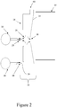
- FIG. 2 illustrates various embodiments of the applicants' teachings in which a different interface configuration is provided.
- chamber 10 as shown is used.
- Chamber 10 comprises orifice plate 14, which defines orifice plate aperture 38, and boundary member 18, which defines aperture 26.
- a sample can enter a mass spectrometer chamber 40 (completely enclosed chamber 40 not shown).
- Chamber 10 is at least partially defined by boundary member 18 and orifice plate 14.
- Gas can be provided to chamber 10 through gas inlet 66.
- Boundary member 18 and orifice plate 14 can be electrically connected to establish an essentially field-free, or near field-free, region between them in the absence of electromagnetic fields associated with sample sources/sample emitters.
- sample source 20 comprising sample emitter 28 is shown proximate, or adjacent, to aperture 26.
- An additional sample source 46 comprising second sample emitter 48 can be located in a position sufficiently distant from the aperture 26. Additional apertures can be defined in boundary member 18 or other regions of chamber 10 to allow additional sample to enter chamber 10. As described above, various ion sources, including electrospray ion sources, are suitable for implementing the applicants' teachings. In addition, the orifice plate aperture 38 can be replaced by any other sampling inlet device known, such as capillary inlets, ion pipes, or heated capillaries.
- sample source 20 comprises a plate 82 and laser irradiation 84, such as a MALDI system, and sample can be generated by laser irradiation 84 of samples on the plate 82.
- samples can optionally be mixed with one or more matrices to facilitate sufficient ionization. Alternatively, samples can be desorbed as neutrals for subsequent ionization by other means generally known.
- the plate can present a geometrical constraint on the location at which second sample source 46 comprising second sample emitter 48 is located.
- Figure 3 shows the boundary member 18 establishing the chamber 10 with primary aperture 26 proximal to heated chamber 12. Aperture 26 can be established flushed with, upstream, or downstream of inlet 42 in heated chamber 12 provided that the gas flow establish by port 62 can carry molecules from second source 46 to inlet 42.
- FIG. 4 illustrates various embodiments of the applicants' teachings in which a different interface configuration is provided.
- second ion source is not located adjacent or proximate to inlet 50.
- Second sample is introduced to chamber 10 through, or with assistance from, channel member 80.
- Channel member 80 can be a tube, although it need not be rounded, nor must it be rectilinear, or other structure that allows the transport of the sample to chamber 10.
- a gas source can be employed to introduce gas into channel member 80 in order to assist the transport of sample to chamber 10. It will be understood from the applicants' teachings that more than one sample source can introduce more than one sample to chamber 10 using the embodiment shown in Figure 4 , or in combination with any of the other embodiments disclosed herein. It will also be apparent that the geometry of channel member 80 and source 46 can be changed without deviating from source principles, for example, the sample can be introduced at different location along the channel member 80.
- the first source 20 can be enclosed in a first source housing 86 and the other source 46 can be enclosed in a corresponding second source housing 88.
- the other source 46 can comprise of more than one sources so that at least one other source 46 can each be enclosed in the same or individual corresponding source housing 88.
- the various embodiments described above can permit ions or molecules from one or more additional sample sources to be delivered to a chamber upstream from a mass spectrometer inlet.
- ions they can be sampled into the instrument simultaneously with ions from a first sample source, or the sampling of ions from the various sample sources may be gated to achieve indexing.
- neutral molecules the neutral molecules can be combined with the ion stream from the first sample source or a sample stream from another sample source and subsequently ionized by gas phase charge transfer or other ionization processes.
- first sample to chamber 10 upstream from aperture 38 can be associated with a first electromagnetic field, such that when the first sample is introduced, it can pass through aperture 38 for analysis by the mass spectrometer.
- At least a second sample of ionized molecules, or neutral molecules that will become ionized, introduced to chamber 10 by a second or more sample source can be substantially repelled by an electromagnetic field associated with introduction of the first sample, and be substantially prevented from passing through aperture 38.
- the second sample which can be used as calibrant, essentially remains in chamber 10.
- the introduction of the second sample can be associated with a second electromagnetic field.
- the second electromagnetic field can be sufficiently remote from the first electromagnetic field such that the second electromagnetic field does not have a detrimental effect on the analysis of the sample by the mass spectrometer.
- the first electromagnetic field is removed so that the first sample is no longer introduced into chamber 10, the second sample is able to pass through aperture 38.
- the first electromagnetic field can subsequently be re-established to once again introduce the first sample.
- This method provides a method of introducing a second sample to a mass spectrometer separately from the first sample in a manner that allows the samples to be indexed. Such indexing of samples can allow for external calibration of the mass spectrometer.
- a method for introducing sample to a mass spectrometer from at least two sources can comprise introducing a first sample to chamber 10 at an entrance point upstream from orifice plate aperture 38 of a mass spectrometer, the first sample being introduced substantially adjacent to orifice plate aperture 38 and introducing at least one other sample to chamber 10 at a position not adjacent to orifice plate aperture 38.
- Chamber 10 can further define gas entrance 62 for allowing the introduction of a gas into chamber 10, such that a gas flow stream is established in which gas flows partially generally toward the entrance point of the first sample and partially toward the sampling inlet.
- the introduction of the first sample is associated with an electromagnetic field and the introduction of the at least one other sample is sufficiently remote from the introduction of the first sample such that the introduction of the at least one other sample does not have a detrimental effect on the analysis of the first sample by the mass spectrometer.
- samples can be gated by controlling one or more ion source electromagnetic fields.
- Other gating methods and devices comprise mechanical, electrical, or pneumatic means, for example.
- Mechanical means can comprise, for example, blocking the introduction of at least one of the samples into chamber 10. This can be achieved by using, for example, one or more beam chopping lenses, or physically moving one or more emitters off axis and away from its aperture.
- Electrical means can comprise, for example, reducing or halting power to at least one of the sample sources.
- Pneumatic means can comprise, for example, controlling the flow of an additional gas source for blowing additional gas, such as a high velocity gas stream, towards one or both of the samples such that that sample is substantially prevented from reaching the sampling inlet.
- additional gas such as a high velocity gas stream
- Other gating methods and devices comprise fluid selectors, in which the flow of sample to an emitter is rapidly turned on and off. Hydraulic valves and/or solenoid valves, for example, can be used to do this.
- Other methods and devices comprise spray controllers, which operate by enabling and disabling the sample emission at the emitter tip. This is usually controlled by electric fields, although mechanical and pneumatic means are also possible. Indexing can be achieved by control of the electrospray potential.
- Electrical indexing of emitters can also be achieved by using lenses located within the chamber proximal to the tip of each emitter.
- Other methods and devices comprise rotating the emitters from their respective aperture, or rotating the apertures, so that the sample is prevented from entering the chamber.
- Other methods and devices comprise ion-beam selectors which are located within the chamber and gate one or more samples in either partial or deep vacuum.
- electrodes can be added to the chamber to apply an extraction potential that diverts sample from the sampling inlet.
- gating can comprise controlling the ion delivery from one or more ion sources to provide sample separately or simultaneously to at least one or more other sources.
- Figure 5 demonstrates various embodiments of applicants' teachings.
- An additional channel 64 is shown defined by and extending radially through heated laminar flow chamber 12. Multiple flow streams are mixed within heated laminar flow chamber 12 to generate a single stream through space 32 and orifice aperture 38.
- Additional channel 64 provides an inlet which can function as an additional inlet within chamber 10 such that the at least one other sample can be sampled into the instrument at about the same time as the first sample. In this fashion, multiple separate ion streams could be sampled simultaneously.
- multiple sampling inlets are enabled such that the sample from sample source 20 and sample from second sample source 46 are transported into different inlets with subsequent mixing in either the atmospheric pressure or vacuum regions.
- a first source can comprise a charged spray and at least one other source can comprise a neutral spray or an oppositely charged spray to that of the first source.
- the sprays from the first and at least one other source can be mixed together to conduct ion-ion or ion-neutral reactions. Neutrals can be charged and polarity can be inverted.
- chamber 10 as herein described can be referred to as, in certain circumstances, an atmospheric pressure interface, or in the same or different circumstances, as a curtain chamber, and may or may not have all of the features presently described for chamber 10.
- quadrupole triple quadrupole and single quadrupole
- TOF including QqTOF
- ion trap mass spectrometers examples of currently-available MS devices within which the applicants' teachings can be advantageously applied.
- any MS device in which the use of a second or more ion source is suitable for use in implementing the applicants' teachings.
- ion source performance can be hindered by electric field interaction when another sample source, such as an ion source, is located in close proximity (see, for example, Rulison and Flagan, Rev. Sci. Instrum., 1993, 64, 683-686 ).
- Figure 6 demonstrates the results of experiments designed to verify elimination of ion source field effects in accordance with the applicants' teachings.
- a sample of reserpine was nanosprayed through a first sample emitter while solvent was electrosprayed through a second sample emitter located distant to a heated laminar flow tube inlet.
- the signal for protonated reserpine fragment ions was monitored as the potential applied to the second sample source was varied.
- the signal generated from the first sample source was not affected by the electromagnetic field associated with the second sample source, demonstrating a lack of detrimental field effects.
- the distance between the two sample sources was approximately 3 centimeters.
- the first ion source emits sample proximal to the inlet, and the aperture in the boundary member is concentric with the inlet, there is no signal reduction compared to a standard configuration (second source and second curtain plate aperture removed).
- the nebulizer flow rate was set sufficiently high to nebulize solvent generated at the tip into the chamber.
- the solvent flow rate was approximately 5 microL/min.
- the first sample source included a nanoflow electrospray source spraying minoxidil at approximately 500 nL/min.
- the spectrum shows the protonated minoxidil ion (m/z 210) as well as a protonated reserpine ion (m/z 609) within the same spectrum, as well as a number of higher intensity phthalate peaks that were present in the solvent provided to the analytical sprayer of the first sample source.
- the reserpine ion was formed by gas phase charge transfer from the ion stream formed by the first sample source.
- Indexing was achieved by stopping the nebulizer gas flow to the nanospray tip to prevent molecule penetration from the second source into the chamber. With this mode of operation, calibrants and ions from the nanospray tip are present within a single mass spectrum. In this manner, it can be possible to achieve internal mass calibration for nanospray experiments or experiments with other types of sources.
- Charging of neutral calibrant molecules can result in a net loss of charge on ions of interest as a result of gas phase charge transfer as shown in Figure 8 .
- a sample of minoxidil was electrosprayed through a nanospray tip and a sample of reserpine (calibrant) was nebulized through a second sprayer assembly.
- Data were collected in the multiple reaction monitoring (MRM) mode of operation and traces for reserpine and minoxidil are displayed in the top and bottom panes of Figure 8 , respectively.
- the MRM dwell times were 100 ms each with 2800 V applied to the ion emitter for minoxidil and a nebulizer setting of 20 for the second emitter assembly.
- the initial settings for the second sprayer were 0 V for the ESI potential and 0 for the nebulizer gas setting.
- the MRM trace displayed approximately 25000 counts per second (cps) for minoxidil fragments.
- the nebulizer for the second ion emitter was turned on with a setting of 55 (about 3 to 3.5 L/minute), thereby nebulizing the neutral calibrant droplets into the chamber through a 2 mm calibrant inlet near the periphery of the curtain plate.
- the heated laminar flow chamber was maintained at 200° C, giving a curtain gas temperature of approximately 100° C.
- the time required to remove the calibrant signal is a result of the time necessary to drain residual pressure on the second nanospray tip nebulizer supply lines, as well as the time necessary to sweep the neutral calibrants from the atmospheric pressure region.
- Figure 8 demonstrates that neutral ionization as a result of the analytical sprayer (first sample source) plume can impact the signal for the analytical sample (approximately a factor of 2 for these data).
- Another method to achieve mass calibration involves the addition of charged calibrant ions to an atmospheric pressure region, or ionization of neutral calibrant molecules within an atmospheric pressure region at a position sufficiently distant from a first sample emitter.
- the atmospheric pressure region is essentially field free (e.g. 500 V on curtain plate and 500 V on heated chamber similar to that shown in Figure 1 )
- ions can also be carried within the curtain gas flow to the heated laminar flow chamber inlet for sampling.
- Figure 9 An example of this is shown in Figure 9 , where a 100 pg/microL sample of reserpine was infused (1 ⁇ L/min) through a second nanospray tip located at the periphery of the curtain plate.
- the ESI potential was 3000 V and the nebulizer was set to 55 (about 3-3.5 L/min).
- the first nanospray tip was removed to substantially ensure a field free configuration proximal to the inlet.
- a substantial MS/MS signal (the signal was down by approximately 50-times relative to a standard optimized configuration on the same system due to the distance from the inlet and the non-concentric nature of the boundary member aperture and the inlet) was generated for this sample, even though the second ion emitter infused charged species into the atmospheric pressure region at a position far removed from the inlet.
- the signal was generated because of the combined effects of the atmospheric pressure region and curtain gas flow (i.e.
- Figure 9 shows that seeding ions into the atmospheric pressure region and using the curtain gas flow to carry them to the inlet can be a viable approach for calibration. Improved signal for calibrant ions can tend to be achieved using a configuration similar to that shown in Figure 4 where calibrants are nebulized through a channel member, such as a tube, to the sampling inlet.
- Electric field penetration can create a potential barrier that may extract charged particles from the curtain gas flow, depending on the relative strength of the gas flow and electric field.
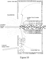
- Figure 10 graphically shows equipotentials (dotted lines) in the vicinity of heated laminar flow chamber inlet when a first ion emitter is a nanoflow ESI sprayer and is located approximately flush with a first curtain plate aperture. This can also be achieved by fabricating a channel into the back or inside of the curtain plate such that the calibrant ions are carried by the nebulizer gas flow through the essentially field-free structure created by the channel.
- a first ion emitter operates with an electrical potential of approximately 3000 V. While this has no effect on neutral calibrants, it will repel positively charged ions from the inlet.
- the charged droplet stream generated from the first ion emitter also repels ions that are present in the curtain gas flow.
- the inventors have found that the electrical repulsion produced by a first ion emitter can be even more pronounced when a spray of charged liquid emanates from it.
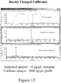
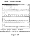
- the competing forces of field repulsion and the presence of a curtain chamber prior to the heated inlet open up the possibility for a new method of calibrant introduction and sprayer indexing as shown in Figure 13 .
- the data presented in Figure 13 were generated by electrospraying 10 pg/ ⁇ L reserpine through the first ion emitter with settings of 2800 V and 10 for the ESI potential and nebulizer gas setting, respectively.
- a sample of 1000 pg/ ⁇ L glufibrinopeptide b was electrosprayed into an atmospheric pressure chamber using settings of 3000 V and 55 for the calibrant ESI potential and nebulizer settings, respectively.
- the potential on the first ion emitter was set to 500 V, essentially generating a field-free region near a heated laminar flow chamber inlet.
- Calibrant ions (glufibrinopeptide b) were drawn into the inlet giving a peak corresponding to the doubly protonated peptide (middle pane).
- the potential applied to the first ion emitter was increased to approximately 2800 V to generate a stable electrospray.
- FIG. 18 shows an orifice plate with an orifice separating the atmospheric pressure source region from the vacuum system of the mass spectrometer.
- a heated laminar flow chamber is sealed to the orifice with a Teflon spacer, similar to the configuration described in Figure 1 , however, the heated laminar flow chamber has a different shape and length ( ⁇ 3 cm).
- a boundary member 18, labeled as a curtain plate forms a chamber with a gas port for introduction of a first gas flow into the chamber.
- the sampling inlet of the laminar flow chamber protrudes outwards from the aperture in the curtain plate such that the gas flow established in the chamber is directed outwards through the curtain plate aperture, towards the sampling inlet.
- the MALDI sample plate is located approximately 3 mm from the inlet of the heated laminar flow chamber to effectively sample the plume of ions and neutrals generated from the surface of the MALDI plate under conditions of laser irradiation.
- An additional nebulizer assisted electrospray emitter is shown at a position substantially removed from the sampling inlet.
- a 7 cm metal tube (labeled Transfer Tube) is threaded into the curtain plate and has approximately a 2.4 mm channel therethrough to transport ions and charged droplets from the nebulizer assisted electrospray source into the chamber established by the curtain plate.
- an additional nebulizer gas can be used to improve transmission of ions and charged droplets into the chamber. Moving the outlet of the transfer tube closer to the sampling inlet also tends to improve transmission of neutral or charged samples from additional sources to the sampling inlet.
- Figure 19 shows an example of data generated using the configuration illustrated in Figure 18 .
- a sample of 1000 pg/ ⁇ L taurocholic acid was electrosprayed at approximately 3 ⁇ L/min through a MicroIonSpray II sprayer into the 7 cm long tube using an electrospray potential of -2500 V and a nebulizer gas setting of approximately 3 L/min.
- the sprayer was pointed directly into the tube so that the nebulizer gas flow could aid in transporting the droplets through the tube.
- a stainless steel MALDI plate was located approximately 3 mm in front of the inlet of the heated laminar flow chamber (2 mm channel) and the potential was adjusted for the data shown in Figure 19 .
- the signal generated for calibrant ions was substantially affected by the potential applied to the MALDI target plate.
- the curtain plate and heated laminar flow chamber were maintained at -605 V.
- the potential applied to the MALDI plate was adjusted from -620 V to -600 V to -560 V.
- the curtain gas flow past the tip was sufficient to carry ions to the inlet.
- the measured ion current for taurocholic acid ions was influenced by the potential applied to the MALDI plate. Under conditions where the curtain gas emanates farther from the sampling inlet, electric field gradients can be used to supplement the motion of ions towards the sampling inlet.
- Figure 20 shows the effect of the potential applied to the MALDI plate on the signal for reserpine calibrant ions sprayed through the calibrant sprayer.
- the potential applied to the curtain plate and inlet was 583 V.
- the calibrant signal was attenuated very significantly when the MALDI plate potential varied by more than approximately +/- 30 V around this value.
- the width of the optimal target plate potential for sampling calibrant ions varied depending upon the spacing between the plate and inlet as well as the physical dimensions of the plate and the distance that the curtain gas emanated behind the tip of the sampling inlet.
- Figure 21 shows an example of indexing achieved under conditions where the curtain gas effect is augmented by a small field between the sampling inlet and the MALDI target plate.
- a sample containing 3 peptides angiotensin I, bradykinin, and angiotensin II
- MALDI matrix a-cyano matrix
- the MALDI source was configured to illuminate the sample using a 100 ⁇ m optical fiber directing the output from a nitrogen laser onto the surface of the sample.
- the MALDI plate was rastored so that the laser light was continuously directed onto a fresh sample surface of a deposit from approximately 1 ⁇ L of the sample/matrix mixture over the course of this experiment.
- the MALDI plate was maintained at approximately 2500 V, such that the ions generated from the MALDI source were sampled into the instrument (4000 QTRAP®) as shown in the lower pane, displaying peaks for the 3 peptides at m/z values of approximately 1047, 1061, and 1297.
- the potential applied to the target plate was lowered to 560 V (i.e.
- the electrosprayed ions contained within the curtain chamber were carried to the sampling inlet by a combination of the curtain gas flow and the potential gradient within the source, giving a mass spectrum dominated by the protonated reserpine ion as shown in the middle pane. In this manner, indexed ion sampling from the 2 different sources can still be achieved by controlling the potential applied to the MALDI target plate.
- the arrangement shown in Figure 18 eliminates these problems as the first source can generate ions of a given polarity proximal to the sampling inlet, and the additional source can generate ions of the opposite polarity at a position substantially removed from the first source, such that there is no detrimental effect on the sampling of ions from the first source.
- the multiple sources can be contained within the same or preferably different source housings.
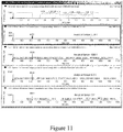
- an atmospheric pressure MALDI source was used to generate positive ions from the same 3 peptide mixture used to generate the data presented in Figure 21 .
- the additional nanoflow source generated negative ions for a sample of 1000 pg/ ⁇ L taurocholic acid sprayed directly into the 7 cm sampling tube.
- the initial potentials were 2500 V, 580 V, 580 V, 150 V, and -2500 V applied to the MALDI plate, curtain plate, heated laminar flow chamber, orifice, and nanoflow sprayer, respectively.
- the curtain gas was set to approximately 1 L/min and the nebulizer for the nanoflow sprayer was set to approximately 3 L/min. Both sources were set to continuously generate ions.
- the positive mode mass spectra showed the presence of the 3 peptides from the MALDI source, with no apparent signal from the nanoflow source as shown in the top pane.
- the potential applied to the MALDI plate was lowered and the polarity of the instrument was switched to negative ion mode.
- the new potentials were -620 V, -620 V, -620 V, -150 V, and -2500 V applied to the MALDI plate, heated inlet, curtain plate, orifice plate, and nanoflow sprayer, respectively.
- Deprotonated taurocholic acid ions from the nanospray source were observed immediately as shown in the middle pane with the peak present at approximately m/z 514.
- the effective curtain gas flow past the sampling inlet eliminated the need for additional electric fields applied between the MALDI plate and the sampling inlet.
- the instrumental polarity was switched back to positive ion mode and the potential applied to the MALDI plate was increased to 2500 V again to permit sampling of the peptide ions from the MALDI source.
- the data in Figure 22 show that it is possible to simultaneously generate ions of opposite polarity from multiple sources and achieve indexing by switching the polarity of the instrument and adjusting the potential applied to the first source.
- the positive and negative ions generated with this device can be contained within a single ion trap for the purposes of conducting ion-ion reactions.
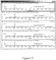
- This experiment was conducted using a pair of nebulizer assisted nanoflow sprayers (MicroIonSpray II) with the configuration shown in Figure 10 .
- Samples containing verapamil and safranin orange were sprayed through the analytical sprayer and the calibrant sprayer, respectively.
- the potentials applied to the 2 sprayers were varied for the data presented in Figure 23 while the nebulizer gas flows were fixed at 0.4 L/min and 3 L/min for the analytical sprayer and the calibrant sprayer, respectively.
- the laminar flow chamber was heated to 100° C while potentials of 580 V, 580 V, and 50 V were applied to the heated laminar flow chamber, curtain plate, and orifice, respectively.
- Panes C and D demonstrate operation of the dual source for external calibration purposes because the analyte and calibrant ions are not present in the same spectrum.
- Pane D shows data generated with potentials of 580 V and 3000 V applied to the analytical sprayer and the calibrant sprayer, respectively.
- the mass spectrum shows the presence of a dominant peak corresponding to ions from the safranin orange calibrant flow.
- Increasing the analytical sprayer potential to 3000 V (Pane C) eliminated all signal for the calibrant ions and produced a dominant peak corresponding to ions from verapamil.
- this source configuration can also be used for internal calibration purposes where the analyte and calibrants are present in the same spectrum.
- calibrant molecules such as aztreonam, cyclosporine, succinyl choline, steroids, and peptides also showed improvements of approximately 3 - 5X when the calibrant sprayer was operated as a negative mode electrospray as opposed to a nebulizer.
- calibrant signals improved as the heater temperature was reduced (more penetration of solvent into the curtain chamber), and as the analytical sprayer was positioned farther from the sampling inlet (more interaction time for the analytical spray with the droplets in the counter-current gas flow).
- Example 10 demonstrates internal calibration and an example of providing field-free conditions in accordance with the applicants' teachings.
- a passage member 90 fabricated of sheet metal was placed on the back of the curtain plate (boundary member) 18 so that the calibrant ions were subjected to field free conditions as they were transported by gas flows from the edge of a second aperture 50 near the periphery of the curtain plate to the region between the curtain plate and a conductive orifice plate 38.
- a first source comprising an electrospray probe (Turbo VTM in this example) was positioned to spray orthogonally to the curtain plate aperture 26 (3 mm) located concentric to the sampling inlet, and a second source comprising a nanoflow sprayer made use of a nebulizer gas to establish a transport gas flow through a channel member 80, such as a tube, that was soldered onto the second aperture.
- a channel member 80 such as a tube
- the electrospray source was positioned approximately 1 cm above the first curtain plate aperture and in an orthogonal configuration as understood by those skilled in the art and continuously generated ions from a sample of glufibrinopeptide, while the second source emitted reserpine ions into the channel member 80.
- calibrant ions could be sampled into the inlet along with analytical ions from the first source.
- indexing of the calibrant ions could be achieved by varying the potential applied to the curtain plate (boundary member).
- the applied potentials were 4500 V, 2800 V, and 100 V applied to the first source, calibrant source, and inlet orifice.
- the potential applied to the curtain plate was varied between 400 V and 100 V.
- the signal generated by the first electrospray source was optimized with 400 V applied to the curtain plate, and there was no signal for the calibrant ions.
- the calibrant ions exiting the passage member on the back or inside surface of the curtain plate (field free passage) were driven by the 300 V/mm field between the curtain plate and conductive orfice and discharged on the metal surface of the orifice plate. Decreasing the curtain plate potential to 100 V generated essentially field free conditions between the curtain plate and the orifice, thereby allowing calibrant ions to be sampled into the inlet along with a portion of the analytical sample. In this fashion, internal calibration can be achieved with switching times on the order of 50 -70 ms.
Landscapes
- Chemical & Material Sciences (AREA)
- Analytical Chemistry (AREA)
- Physics & Mathematics (AREA)
- Engineering & Computer Science (AREA)
- Plasma & Fusion (AREA)
- Other Investigation Or Analysis Of Materials By Electrical Means (AREA)
- Electron Tubes For Measurement (AREA)
Claims (26)
- Verfahren zum Einführen von Proben zu einem Massenspektrometer von mindestens zwei Quellen, das Verfahren umfassend:Einführen einer ersten der Proben durch einen ersten Eingangspunkt (26) in eine Kammer (10) in Kommunikation mit einem Probeneinlass (38) zu dem Massenspektrometer (40), wobei das erste Eingangspunkt (26) in einem Abgrenzungselement (18) definiert ist, das mindestens teilweise die Kammer (10) definiert, das Abgrenzungselement (18) zwischen mindestens einer der Quellen und dem Probeneinlass (38) positioniert ist, der erste Eingangspunkt koaxial zu dem Probeneinlass (38) ist, die erste der Proben zu dem Probeneinlass (38) eingeführt wird;Einführen mindestens einer zweiten der Proben durch mindestens einen anderen Eingangspunkt (50), der in der Kammer (10) definiert ist, sodass die mindestens zweite der Proben durch die Quelle der mindestens zweiten der Proben nicht direkt zu dem Probeneinlass (38) übertragen wird,Einführen eines Gases in die Kammer durch einen Gaseingang (62), wobei ein Gasflussstrom hergestellt wird, in dem der Gasflussstrom teilweise zu dem ersten Eingangspunkt und teilweise zu dem Probeneinlass (38) strömt, sodass der Gasflussstrom generell als ein Kanal zum Transportieren der mindestens zweiten der Proben von dem mindestens einen anderen Eingangspunkt (50) zu dem Probeneinlass (38) wirkt, um eine Probennahme der mindestens zweiten der Proben zu ermöglichen oder signifikant zu verbessern,Herstellen feldfreier Bedingungen oder nahezu feldfreier Bedingungen in der Abwesenheit von externen elektromagnetischen Feldern in Verbindung mit den Quellen (20, 46) in mindestens einer Region der Kammer (10), um mindestens der zweiten der Proben zu ermöglichen, durch den Gasflussstrom zu dem Probeneinlass (38) gerichtet zu werden.
- Verfahren nach Anspruch 1, wobei sich der erste Eingangspunkt (26) in einem Abstand von mindestens 3 Millimetern von dem mindestens einen anderen Eingangspunkt (50) befindet.
- Verfahren nach Anspruch 1, wobei mindestens eine der Proben Ionen umfasst.
- Verfahren nach Anspruch 3, wobei die erste der Proben Ionen umfasst und mindestens die zweite der Proben Ionen der entgegengesetzten Polarität zu den Ionen der ersten der Proben umfasst.
- Verfahren nach Anspruch 1, wobei mindestens eine der Proben Ionen umfasst und die zweite der Proben neutrale Moleküle umfasst.
- Verfahren nach Anspruch 5, wobei die neutralen Moleküle geladen werden, bevor sie durch das Massenspektrometer analysiert werden.
- Verfahren nach Anspruch 5 oder 6, wobei Ionen der ersten der Proben und Neutrale der zweiten der Proben miteinander gemischt werden, um Ionen-Neutral-Reaktionen durchzuführen.
- Verfahren nach Anspruch 1, ferner umfassend ein Bereitstellen von mindestens einer Wärmequelle.
- Verfahren nach Anspruch 1, wobei der Probeneinlass erhitzt wird.
- Verfahren nach Anspruch 1, wobei mindestens die zweite der Proben kalibrierende Moleküle umfasst.
- Verfahren nach Anspruch 1, ferner umfassend ein Steuern des Einführens der ersten der Proben und der zweiten der Proben in den Probeneinlass, und vorzugsweise ferner umfassend ein Steuern der mindestens der zweiten der Proben durch Verändern des angewendeten Potenzials auf die erste der Proben.
- Verfahren nach Anspruch 11, wobei das Steuern ein Variieren des angewendeten Potenzials auf das Abgrenzungselement umfasst.
- Verfahren nach Anspruch 1, wobei die erste der Proben Ionen umfasst und mindestens die zweite der Proben Ionen entgegengesetzter Polarität zu der ersten der Proben umfasst, und wobei Ionen der ersten der Proben und Ionen der zweiten der Proben miteinander gemischt werden, um Ionen-Ionen-Reaktionen durchzuführen, oder wobei die erste der Proben und die zweite der Proben miteinander gemischt werden, um Ladungsumkehrungsexperimente durchzuführen.
- Verfahren nach Anspruch 1, wobei die erste und die zweite der Proben Ionen umfasst und wobei Ionen der ersten der Proben und Ionen der zweiten der Proben gesteuert werden, um ein externe Kalibration durchzuführen, oder wobei die erste der Proben und die zweite der Proben miteinander gemischt werden, um eine interne Kalibration durchzuführen.
- Verfahren nach Anspruch 1, wobei die erste der Proben durch den ersten Eingangspunkt (26) als ein Spray aus geladenen Tröpfchen einer ersten Polarität und die zweite der Proben durch den mindestens einen anderen Eingangspunkt (50) als eines von einem Spray aus Tröpfchen einer entgegengesetzten Polarität zu den geladenen Tröpfchen der ersten der Proben eingeführt werden, und wobei einer Spray aus Tröpfchen neutraler Polarität und die Tröpfchen aus der zweiten der Proben mit den Tröpfchen aus der ersten der Proben gemischt werden.
- Verfahren nach Anspruch 1, ferner umfassend ein Bereitstellen eines Kanalelements (80), das an dem mindestens einen anderen Eingangspunkt (50) angebracht ist.
- Verfahren nach Anspruch 1 oder 16, ferner umfassend ein Bereitstellen eines Durchgangselements (80), das an der Innenseite des Abgrenzungselements angebracht ist, wobei das Durchgangselement anliegend an dem mindestens einen anderen Eingangspunkt zum Bereitstellen feldfreier Bedingungen für mindestens eine Region der Kammer angebracht ist.
- Schnittstellenvorrichtung zum Einführen von mindestens einer Probe in ein Massenspektrometer, die Schnittstellenvorrichtung umfassend,
einen Probeneinlass (38) zu dem Massenspektrometer (40);
ein Abgrenzungselement (18), das mindestens teilweise eine Kammer (10) in Kommunikation mit dem Probeneinlass (38) definiert;
eine erste Öffnung (26), die in dem Abgrenzungselement (18) definiert ist, durch die eine erste Quelle (20) eine erste Probe emittieren kann, wobei die erste Öffnung (26) koaxial zu dem Probeneinlass (38) ist und die erste Probe zu dem Probeneinlass (38) für einen Durchgang dort hindurch gerichtet wird;
mindestens eine andere Öffnung (50), die in der Kammer (10) definiert ist, durch die mindestens eine andere Quelle (46) mindestens eine zweite Probe in die Kammer (10) einführen kann, sodass die zweite Probe von der mindestens einen anderen Quelle (46) nicht direkt zu dem Probeneinlass (38) übertragen wird; und
einen Gaseingang (62) zum Einführen eines Gases in die Kammer (10), wobei ein Gasflussstrom hergestellt wird, in dem der Gasflussstrom teilweise zu der ersten Öffnung (26) strömt, die in dem Abgrenzungselement (18) definiert ist, und teilweise zu dem Probeneinlass (38), wobei das Abgrenzungselement (18) zwischen mindestens einer der Quellen und dem Probeneinlass (38) positioniert ist, sodass der Gasflussstrom generell als ein Kanal zum Transportieren der zweiten Probe von dem mindestens einen anderen Eingangsanschluss (50) zu dem Probeneinlass (38) wirkt, um eine Probennahme der zweiten Probe zu ermöglichen oder signifikant zu verbessern,
wobei die Kammer (10) mindestens eine Region hat, wo feldfreie Bedingungen oder nahezu feldfreie Bedingungen hergestellt sind in der Abwesenheit von externen elektromagnetischen Feldern in Verbindung mit den Quellen (20, 46), um der mindestens zweiten Probe aus der mindestens einen anderen Öffnung (50), die in der Kammer (10) definiert ist, zu ermöglichen, durch den Gasflussstrom zu dem Probeneinlass (38) gerichtet zu werden. - Schnittstellenvorrichtung nach Anspruch 18, ferner umfassend mindestens eine Wärmequelle, wobei sich die mindestens eine Wärmequelle außerhalb der Kammer oder in der ersten Quelle befindet.
- Schnittstellenvorrichtung nach Anspruch 19, ferner umfassend mindestens eine Wärmequelle, die sich in der Kammer befindet, und wobei die Wärmequelle eine Laminarröhre umfasst.
- Schnittstellenvorrichtung nach Anspruch 19, ferner umfassend eine Klappe zum Steuern der Einführung der ersten Probe und der zweiten Probe in den Probeneinlass (38).
- Schnittstellenvorrichtung nach Anspruch 21, ferner umfassend eine zweite Gasquelle zum Blasen von zusätzlichem Gas zu mindestens einer von der ersten Probe und der mindestens zweiten Probe, und im Wesentlichen senkrecht zu mindestens einer von der ersten und zweite Quelle, sodass bei mindestens einer von der ersten Probe und der mindestens zweiten Probe verhindert ist, dass sie den Probeneinlass erreicht, wobei die Klappe eine Steuereinheit zum Steuern des zusätzlichen Gasflusses umfasst.
- Schnittstellenvorrichtung nach Anspruch 18, ferner umfassend ein Kanalelement, das an der mindestens einen anderen Öffnung angebracht ist, in das die mindestens eine andere Quelle die mindestens zweite Probe die mindestens eine andere Öffnung einführen kann.
- Schnittstellenvorrichtung nach Anspruch 23, wobei das Kanalelement eine Röhre umfasst.
- Schnittstellenvorrichtung nach Anspruch 18, 23 oder 24, ferner umfassend ein Durchgangselement, das an der Innenseite des Abgrenzungselements (18) angebracht ist, wobei das Durchgangselement anliegend an der mindestens einen anderen Öffnung zum Bereitstellen feldfreier Bedingungen für die mindestens eine Region der Kammer angebracht ist, vorzugsweise wobei das Durchgangselement ein leitfähiges Material umfasst.
- Schnittstellenvorrichtung nach Anspruch 25, wobei das leitfähige Material Blech umfasst.
Applications Claiming Priority (3)
| Application Number | Priority Date | Filing Date | Title |
|---|---|---|---|
| US82681106P | 2006-09-25 | 2006-09-25 | |
| US86712306P | 2006-11-23 | 2006-11-23 | |
| PCT/CA2007/001716 WO2008037073A1 (en) | 2006-09-25 | 2007-09-25 | Multiple sample sources for use with mass spectrometers, and apparatus, devices, and methods therefor |
Publications (3)
| Publication Number | Publication Date |
|---|---|
| EP2070102A1 EP2070102A1 (de) | 2009-06-17 |
| EP2070102A4 EP2070102A4 (de) | 2011-11-30 |
| EP2070102B1 true EP2070102B1 (de) | 2018-03-14 |
Family
ID=39229674
Family Applications (1)
| Application Number | Title | Priority Date | Filing Date |
|---|---|---|---|
| EP07815905.0A Active EP2070102B1 (de) | 2006-09-25 | 2007-09-25 | Mehrfachprobenquellen zur verwendung mit massenspektrometern und vorrichtungen, einrichtungen und verfahren dafür |
Country Status (5)
| Country | Link |
|---|---|
| US (1) | US7679053B2 (de) |
| EP (1) | EP2070102B1 (de) |
| JP (1) | JP2010504504A (de) |
| CA (1) | CA2663698C (de) |
| WO (1) | WO2008037073A1 (de) |
Families Citing this family (29)
| Publication number | Priority date | Publication date | Assignee | Title |
|---|---|---|---|---|
| US8173959B1 (en) * | 2007-07-21 | 2012-05-08 | Implant Sciences Corporation | Real-time trace detection by high field and low field ion mobility and mass spectrometry |
| US9905409B2 (en) * | 2007-11-30 | 2018-02-27 | Waters Technologies Corporation | Devices and methods for performing mass analysis |
| GB0809950D0 (en) | 2008-05-30 | 2008-07-09 | Thermo Fisher Scient Bremen | Mass spectrometer |
| WO2009155007A1 (en) * | 2008-05-30 | 2009-12-23 | Thermo Finnigan Llc | Method and apparatus for generation of reagent ions in a mass spectrometer |
| US8969795B2 (en) * | 2008-10-06 | 2015-03-03 | Shimadzu Corporation | Curtain gas filter for mass- and mobility-analyzers that excludes ion-source gases and ions of high mobility |
| WO2010045049A1 (en) * | 2008-10-13 | 2010-04-22 | Purdue Research Foundation | Systems and methods for transfer of ions for analysis |
| WO2010081830A1 (en) * | 2009-01-14 | 2010-07-22 | Sociedad Europea De Análisis Diferencial De Movilidad, S.L. | Improved ionizer for vapor analysis decoupling the ionization region from the analyzer |
| US8927295B2 (en) * | 2009-09-10 | 2015-01-06 | Purdue Research Foundation | Method and apparatus for conversion of multiple analyte cation types to a single analyte anion type via ion/ion charge inversion |
| EP2363877A1 (de) * | 2010-03-02 | 2011-09-07 | Tofwerk AG | Verfahren zur chemischen Analyse |
| CN103069538B (zh) * | 2010-08-19 | 2016-05-11 | 莱克公司 | 具有软电离辉光放电和调节器的质谱仪 |
| EP2621612B1 (de) * | 2010-09-27 | 2022-01-05 | DH Technologies Development Pte. Ltd. | Verfahren und system zur bereitstellung eines doppelgasvorhangs für ein massenspektrometriesystem |
| JPWO2012090914A1 (ja) * | 2010-12-27 | 2014-06-05 | 株式会社 資生堂 | 質量分析方法、質量分析計及び質量分析システム |
| WO2012090915A1 (ja) * | 2010-12-27 | 2012-07-05 | 株式会社資生堂 | 質量分析方法、イオン生成装置及び質量分析システム |
| US20120228490A1 (en) * | 2011-03-13 | 2012-09-13 | Excellims Corporation | Apparatus and method for ion mobility spectrometry and sample introduction |
| US9395333B2 (en) | 2011-06-22 | 2016-07-19 | Implant Sciences Corporation | Ion mobility spectrometer device with embedded faims |
| US9068943B2 (en) | 2011-04-27 | 2015-06-30 | Implant Sciences Corporation | Chemical analysis using hyphenated low and high field ion mobility |
| WO2013152344A1 (en) | 2012-04-06 | 2013-10-10 | Implant Sciences Corporation | Selective ionization using high frequency filtering of reactive ions |
| US8975573B2 (en) | 2013-03-11 | 2015-03-10 | 1St Detect Corporation | Systems and methods for calibrating mass spectrometers |
| TWI488216B (zh) * | 2013-04-18 | 2015-06-11 | 國立中山大學 | 多游離源的質譜游離裝置及質譜分析系統 |
| WO2015040379A1 (en) | 2013-09-20 | 2015-03-26 | Micromass Uk Limited | Automated beam check |
| US9905406B2 (en) | 2013-10-23 | 2018-02-27 | Micromass Uk Limited | Charge-stripping of multiply-charged ions |
| CN110024076B (zh) * | 2016-11-29 | 2022-05-10 | 株式会社岛津制作所 | 离子化装置以及质谱分析装置 |
| CA3302055A1 (en) * | 2018-02-13 | 2026-03-02 | Biomerieux, Inc. | Load lock chamber assemblies for sample analysis systems and related mass spectrometer systems and methods |
| US11232938B2 (en) | 2018-06-29 | 2022-01-25 | Dh Technologies Development Pte. Ltd. | Sampling probe and sampling interface for mass spectrometry |
| JP7140282B2 (ja) * | 2019-05-27 | 2022-09-21 | 株式会社島津製作所 | 質量分析装置 |
| EP3817029A1 (de) * | 2019-10-30 | 2021-05-05 | Tofwerk AG | Verfahren und vorrichtung zur massenanalyse einer ersten probe |
| WO2021224973A1 (ja) * | 2020-05-08 | 2021-11-11 | 株式会社島津製作所 | ガスクロマトグラフ質量分析計 |
| US11621153B2 (en) * | 2020-06-15 | 2023-04-04 | Quadrocore Corp. | Mass spectrometry of surface contamination |
| US20240282564A1 (en) * | 2021-06-22 | 2024-08-22 | Dh Technologies Development Pte. Ltd. | Automated systems and methods for separating compounds |
Citations (3)
| Publication number | Priority date | Publication date | Assignee | Title |
|---|---|---|---|---|
| US5504327A (en) * | 1993-11-04 | 1996-04-02 | Hv Ops, Inc. (H-Nu) | Electrospray ionization source and method for mass spectrometric analysis |
| US6501073B1 (en) * | 2000-10-04 | 2002-12-31 | Thermo Finnigan Llc | Mass spectrometer with a plurality of ionization probes |
| US20030071209A1 (en) * | 1999-03-05 | 2003-04-17 | Park Melvin A. | Ionization chamber for atmospheric pressure ionization mass spectrometry |
Family Cites Families (9)
| Publication number | Priority date | Publication date | Assignee | Title |
|---|---|---|---|---|
| US5576540A (en) * | 1995-08-11 | 1996-11-19 | Mds Health Group Limited | Mass spectrometer with radial ejection |
| JP2001516140A (ja) * | 1997-09-12 | 2001-09-25 | アナリティカ オブ ブランフォード インコーポレーテッド | 多重試料導入質量分光測定法 |
| US6191418B1 (en) * | 1998-03-27 | 2001-02-20 | Synsorb Biotech, Inc. | Device for delivery of multiple liquid sample streams to a mass spectrometer |
| EP1277045A2 (de) * | 1999-12-15 | 2003-01-22 | MDS Inc. | Parallele probenzufuhr in einem eletrosprühmassenspektrometer mit hilfe von elektronischer indexierung, basierend auf einer merzahl von ioneneilässen |
| US6657191B2 (en) * | 2001-03-02 | 2003-12-02 | Bruker Daltonics Inc. | Means and method for multiplexing sprays in an electrospray ionization source |
| ATE476751T1 (de) * | 2001-03-29 | 2010-08-15 | Wisconsin Alumni Res Found | Piezoelektrisch geladene tröpfchenquelle |
| US20030224529A1 (en) * | 2002-05-31 | 2003-12-04 | Romaine Maiefski | Dual ion source assembly |
| US6646257B1 (en) * | 2002-09-18 | 2003-11-11 | Agilent Technologies, Inc. | Multimode ionization source |
| CA2516264C (en) * | 2003-02-14 | 2012-10-23 | Mds Sciex | Atmospheric pressure charged particle discriminator for mass spectrometry |
-
2007
- 2007-09-25 WO PCT/CA2007/001716 patent/WO2008037073A1/en not_active Ceased
- 2007-09-25 EP EP07815905.0A patent/EP2070102B1/de active Active
- 2007-09-25 JP JP2009528565A patent/JP2010504504A/ja active Pending
- 2007-09-25 CA CA2663698A patent/CA2663698C/en not_active Expired - Fee Related
- 2007-09-25 US US11/860,899 patent/US7679053B2/en active Active
Patent Citations (3)
| Publication number | Priority date | Publication date | Assignee | Title |
|---|---|---|---|---|
| US5504327A (en) * | 1993-11-04 | 1996-04-02 | Hv Ops, Inc. (H-Nu) | Electrospray ionization source and method for mass spectrometric analysis |
| US20030071209A1 (en) * | 1999-03-05 | 2003-04-17 | Park Melvin A. | Ionization chamber for atmospheric pressure ionization mass spectrometry |
| US6501073B1 (en) * | 2000-10-04 | 2002-12-31 | Thermo Finnigan Llc | Mass spectrometer with a plurality of ionization probes |
Also Published As
| Publication number | Publication date |
|---|---|
| US7679053B2 (en) | 2010-03-16 |
| EP2070102A4 (de) | 2011-11-30 |
| CA2663698A1 (en) | 2008-04-03 |
| WO2008037073A1 (en) | 2008-04-03 |
| US20080073502A1 (en) | 2008-03-27 |
| JP2010504504A (ja) | 2010-02-12 |
| CA2663698C (en) | 2017-08-22 |
| EP2070102A1 (de) | 2009-06-17 |
Similar Documents
| Publication | Publication Date | Title |
|---|---|---|
| EP2070102B1 (de) | Mehrfachprobenquellen zur verwendung mit massenspektrometern und vorrichtungen, einrichtungen und verfahren dafür | |
| JP2010504504A5 (de) | ||
| US7315020B2 (en) | Ionization chamber for atmospheric pressure ionization mass spectrometry | |
| Manisali et al. | Electrospray ionization source geometry for mass spectrometry: past, present, and future | |
| US6949739B2 (en) | Ionization at atmospheric pressure for mass spectrometric analyses | |
| JP6263776B2 (ja) | インパクタスプレーイオン化源を介した、キャピラリー電気泳動から質量分析計のへのインターフェース化 | |
| JP3079055B2 (ja) | エレクトロスプレー、大気圧化学的イオン化質量分析計およびイオン発生源 | |
| US8546750B2 (en) | Mass spectrometer interface | |
| CA2725612C (en) | Single and multiple operating mode ion sources with atmospheric pressure chemical ionization | |
| US8723110B2 (en) | Atmospheric pressure ion source for mass spectrometry | |
| US6809312B1 (en) | Ionization source chamber and ion beam delivery system for mass spectrometry | |
| CA2184982C (en) | Electrospray and atmospheric pressure chemical ionization sources | |
| US7253406B1 (en) | Remote reagent chemical ionization source | |
| US6060705A (en) | Electrospray and atmospheric pressure chemical ionization sources | |
| JP2010537371A (ja) | 真空以上の圧力での試料のイオン化 | |
| US8481927B2 (en) | High yield atmospheric pressure ion source for ion spectrometers in vacuum | |
| US20030062474A1 (en) | Electrospray ion source for mass spectrometry with atmospheric pressure desolvating capabilities | |
| CN109716482A (zh) | 用于控制离子污染的方法及系统 | |
| EP2981983B1 (de) | Verbesserungen bei der herstellung und steuerung von ionen | |
| JP2011113832A (ja) | 質量分析装置 | |
| US8502162B2 (en) | Atmospheric pressure ionization apparatus and method | |
| Schneider et al. | Calibrant delivery for mass spectrometry |
Legal Events
| Date | Code | Title | Description |
|---|---|---|---|
| PUAI | Public reference made under article 153(3) epc to a published international application that has entered the european phase |
Free format text: ORIGINAL CODE: 0009012 |
|
| 17P | Request for examination filed |
Effective date: 20090326 |
|
| AK | Designated contracting states |
Kind code of ref document: A1 Designated state(s): AT BE BG CH CY CZ DE DK EE ES FI FR GB GR HU IE IS IT LI LT LU LV MC MT NL PL PT RO SE SI SK TR |
|
| AX | Request for extension of the european patent |
Extension state: AL BA HR MK RS |
|
| RAP1 | Party data changed (applicant data changed or rights of an application transferred) |
Owner name: APPLIED BIOSYSTEMS (CANADA) LIMITED Owner name: MDS ANALYTICAL TECHNOLOGIES, A BUSINESS UNIT OF M |
|
| REG | Reference to a national code |
Ref country code: DE Ref legal event code: R079 Ref document number: 602007054234 Country of ref document: DE Free format text: PREVIOUS MAIN CLASS: H01J0049040000 Ipc: H01J0049100000 |
|
| A4 | Supplementary search report drawn up and despatched |
Effective date: 20111103 |
|
| RIC1 | Information provided on ipc code assigned before grant |
Ipc: H01J 49/00 20060101ALI20111027BHEP Ipc: H01J 49/06 20060101ALI20111027BHEP Ipc: H01J 49/16 20060101ALI20111027BHEP Ipc: H01J 49/10 20060101AFI20111027BHEP |
|
| DAX | Request for extension of the european patent (deleted) | ||
| 17Q | First examination report despatched |
Effective date: 20121113 |
|
| RAP1 | Party data changed (applicant data changed or rights of an application transferred) |
Owner name: DH TECHNOLOGIES DEVELOPMENT PTE. LTD. |
|
| GRAP | Despatch of communication of intention to grant a patent |
Free format text: ORIGINAL CODE: EPIDOSNIGR1 |
|
| STAA | Information on the status of an ep patent application or granted ep patent |
Free format text: STATUS: GRANT OF PATENT IS INTENDED |
|
| INTG | Intention to grant announced |
Effective date: 20171002 |
|
| GRAS | Grant fee paid |
Free format text: ORIGINAL CODE: EPIDOSNIGR3 |
|
| GRAA | (expected) grant |
Free format text: ORIGINAL CODE: 0009210 |
|
| STAA | Information on the status of an ep patent application or granted ep patent |
Free format text: STATUS: THE PATENT HAS BEEN GRANTED |
|
| RAP1 | Party data changed (applicant data changed or rights of an application transferred) |
Owner name: DH TECHNOLOGIES DEVELOPMENT PTE. LTD. |
|
| RIN1 | Information on inventor provided before grant (corrected) |
Inventor name: COVEY, THOMAS R. Inventor name: SCHNEIDER, BRADLEY B. |
|
| AK | Designated contracting states |
Kind code of ref document: B1 Designated state(s): AT BE BG CH CY CZ DE DK EE ES FI FR GB GR HU IE IS IT LI LT LU LV MC MT NL PL PT RO SE SI SK TR |
|
| REG | Reference to a national code |
Ref country code: GB Ref legal event code: FG4D |
|
| REG | Reference to a national code |
Ref country code: AT Ref legal event code: REF Ref document number: 979627 Country of ref document: AT Kind code of ref document: T Effective date: 20180315 Ref country code: CH Ref legal event code: EP |
|
| REG | Reference to a national code |
Ref country code: IE Ref legal event code: FG4D |
|
| REG | Reference to a national code |
Ref country code: DE Ref legal event code: R096 Ref document number: 602007054234 Country of ref document: DE |
|
| REG | Reference to a national code |
Ref country code: NL Ref legal event code: MP Effective date: 20180314 |
|
| REG | Reference to a national code |
Ref country code: LT Ref legal event code: MG4D |
|
| PG25 | Lapsed in a contracting state [announced via postgrant information from national office to epo] |
Ref country code: FI Free format text: LAPSE BECAUSE OF FAILURE TO SUBMIT A TRANSLATION OF THE DESCRIPTION OR TO PAY THE FEE WITHIN THE PRESCRIBED TIME-LIMIT Effective date: 20180314 Ref country code: CY Free format text: LAPSE BECAUSE OF FAILURE TO SUBMIT A TRANSLATION OF THE DESCRIPTION OR TO PAY THE FEE WITHIN THE PRESCRIBED TIME-LIMIT Effective date: 20180314 Ref country code: LT Free format text: LAPSE BECAUSE OF FAILURE TO SUBMIT A TRANSLATION OF THE DESCRIPTION OR TO PAY THE FEE WITHIN THE PRESCRIBED TIME-LIMIT Effective date: 20180314 Ref country code: ES Free format text: LAPSE BECAUSE OF FAILURE TO SUBMIT A TRANSLATION OF THE DESCRIPTION OR TO PAY THE FEE WITHIN THE PRESCRIBED TIME-LIMIT Effective date: 20180314 |
|
| REG | Reference to a national code |
Ref country code: AT Ref legal event code: MK05 Ref document number: 979627 Country of ref document: AT Kind code of ref document: T Effective date: 20180314 |
|
| PG25 | Lapsed in a contracting state [announced via postgrant information from national office to epo] |
Ref country code: SE Free format text: LAPSE BECAUSE OF FAILURE TO SUBMIT A TRANSLATION OF THE DESCRIPTION OR TO PAY THE FEE WITHIN THE PRESCRIBED TIME-LIMIT Effective date: 20180314 Ref country code: LV Free format text: LAPSE BECAUSE OF FAILURE TO SUBMIT A TRANSLATION OF THE DESCRIPTION OR TO PAY THE FEE WITHIN THE PRESCRIBED TIME-LIMIT Effective date: 20180314 Ref country code: GR Free format text: LAPSE BECAUSE OF FAILURE TO SUBMIT A TRANSLATION OF THE DESCRIPTION OR TO PAY THE FEE WITHIN THE PRESCRIBED TIME-LIMIT Effective date: 20180615 Ref country code: BG Free format text: LAPSE BECAUSE OF FAILURE TO SUBMIT A TRANSLATION OF THE DESCRIPTION OR TO PAY THE FEE WITHIN THE PRESCRIBED TIME-LIMIT Effective date: 20180614 |
|
| REG | Reference to a national code |
Ref country code: FR Ref legal event code: PLFP Year of fee payment: 12 |
|
| PG25 | Lapsed in a contracting state [announced via postgrant information from national office to epo] |
Ref country code: EE Free format text: LAPSE BECAUSE OF FAILURE TO SUBMIT A TRANSLATION OF THE DESCRIPTION OR TO PAY THE FEE WITHIN THE PRESCRIBED TIME-LIMIT Effective date: 20180314 Ref country code: NL Free format text: LAPSE BECAUSE OF FAILURE TO SUBMIT A TRANSLATION OF THE DESCRIPTION OR TO PAY THE FEE WITHIN THE PRESCRIBED TIME-LIMIT Effective date: 20180314 Ref country code: IT Free format text: LAPSE BECAUSE OF FAILURE TO SUBMIT A TRANSLATION OF THE DESCRIPTION OR TO PAY THE FEE WITHIN THE PRESCRIBED TIME-LIMIT Effective date: 20180314 Ref country code: RO Free format text: LAPSE BECAUSE OF FAILURE TO SUBMIT A TRANSLATION OF THE DESCRIPTION OR TO PAY THE FEE WITHIN THE PRESCRIBED TIME-LIMIT Effective date: 20180314 Ref country code: PL Free format text: LAPSE BECAUSE OF FAILURE TO SUBMIT A TRANSLATION OF THE DESCRIPTION OR TO PAY THE FEE WITHIN THE PRESCRIBED TIME-LIMIT Effective date: 20180314 |
|
| PG25 | Lapsed in a contracting state [announced via postgrant information from national office to epo] |
Ref country code: SK Free format text: LAPSE BECAUSE OF FAILURE TO SUBMIT A TRANSLATION OF THE DESCRIPTION OR TO PAY THE FEE WITHIN THE PRESCRIBED TIME-LIMIT Effective date: 20180314 Ref country code: AT Free format text: LAPSE BECAUSE OF FAILURE TO SUBMIT A TRANSLATION OF THE DESCRIPTION OR TO PAY THE FEE WITHIN THE PRESCRIBED TIME-LIMIT Effective date: 20180314 Ref country code: CZ Free format text: LAPSE BECAUSE OF FAILURE TO SUBMIT A TRANSLATION OF THE DESCRIPTION OR TO PAY THE FEE WITHIN THE PRESCRIBED TIME-LIMIT Effective date: 20180314 |
|
| REG | Reference to a national code |
Ref country code: DE Ref legal event code: R097 Ref document number: 602007054234 Country of ref document: DE |
|
| PG25 | Lapsed in a contracting state [announced via postgrant information from national office to epo] |
Ref country code: PT Free format text: LAPSE BECAUSE OF FAILURE TO SUBMIT A TRANSLATION OF THE DESCRIPTION OR TO PAY THE FEE WITHIN THE PRESCRIBED TIME-LIMIT Effective date: 20180716 |
|
| PLBE | No opposition filed within time limit |
Free format text: ORIGINAL CODE: 0009261 |
|
| STAA | Information on the status of an ep patent application or granted ep patent |
Free format text: STATUS: NO OPPOSITION FILED WITHIN TIME LIMIT |
|
| PG25 | Lapsed in a contracting state [announced via postgrant information from national office to epo] |
Ref country code: DK Free format text: LAPSE BECAUSE OF FAILURE TO SUBMIT A TRANSLATION OF THE DESCRIPTION OR TO PAY THE FEE WITHIN THE PRESCRIBED TIME-LIMIT Effective date: 20180314 |
|
| 26N | No opposition filed |
Effective date: 20181217 |
|
| PG25 | Lapsed in a contracting state [announced via postgrant information from national office to epo] |
Ref country code: SI Free format text: LAPSE BECAUSE OF FAILURE TO SUBMIT A TRANSLATION OF THE DESCRIPTION OR TO PAY THE FEE WITHIN THE PRESCRIBED TIME-LIMIT Effective date: 20180314 |
|
| PG25 | Lapsed in a contracting state [announced via postgrant information from national office to epo] |
Ref country code: MC Free format text: LAPSE BECAUSE OF FAILURE TO SUBMIT A TRANSLATION OF THE DESCRIPTION OR TO PAY THE FEE WITHIN THE PRESCRIBED TIME-LIMIT Effective date: 20180314 |
|
| REG | Reference to a national code |
Ref country code: CH Ref legal event code: PL |
|
| REG | Reference to a national code |
Ref country code: BE Ref legal event code: MM Effective date: 20180930 |
|
| REG | Reference to a national code |
Ref country code: IE Ref legal event code: MM4A |
|
| PG25 | Lapsed in a contracting state [announced via postgrant information from national office to epo] |
Ref country code: LU Free format text: LAPSE BECAUSE OF NON-PAYMENT OF DUE FEES Effective date: 20180925 |
|
| PG25 | Lapsed in a contracting state [announced via postgrant information from national office to epo] |
Ref country code: IE Free format text: LAPSE BECAUSE OF NON-PAYMENT OF DUE FEES Effective date: 20180925 |
|
| PG25 | Lapsed in a contracting state [announced via postgrant information from national office to epo] |
Ref country code: BE Free format text: LAPSE BECAUSE OF NON-PAYMENT OF DUE FEES Effective date: 20180930 Ref country code: CH Free format text: LAPSE BECAUSE OF NON-PAYMENT OF DUE FEES Effective date: 20180930 Ref country code: LI Free format text: LAPSE BECAUSE OF NON-PAYMENT OF DUE FEES Effective date: 20180930 |
|
| PG25 | Lapsed in a contracting state [announced via postgrant information from national office to epo] |
Ref country code: MT Free format text: LAPSE BECAUSE OF NON-PAYMENT OF DUE FEES Effective date: 20180925 |
|
| PG25 | Lapsed in a contracting state [announced via postgrant information from national office to epo] |
Ref country code: TR Free format text: LAPSE BECAUSE OF FAILURE TO SUBMIT A TRANSLATION OF THE DESCRIPTION OR TO PAY THE FEE WITHIN THE PRESCRIBED TIME-LIMIT Effective date: 20180314 |
|
| PG25 | Lapsed in a contracting state [announced via postgrant information from national office to epo] |
Ref country code: HU Free format text: LAPSE BECAUSE OF FAILURE TO SUBMIT A TRANSLATION OF THE DESCRIPTION OR TO PAY THE FEE WITHIN THE PRESCRIBED TIME-LIMIT; INVALID AB INITIO Effective date: 20070925 |
|
| PG25 | Lapsed in a contracting state [announced via postgrant information from national office to epo] |
Ref country code: IS Free format text: LAPSE BECAUSE OF FAILURE TO SUBMIT A TRANSLATION OF THE DESCRIPTION OR TO PAY THE FEE WITHIN THE PRESCRIBED TIME-LIMIT Effective date: 20180714 |
|
| P01 | Opt-out of the competence of the unified patent court (upc) registered |
Effective date: 20230530 |
|
| PGFP | Annual fee paid to national office [announced via postgrant information from national office to epo] |
Ref country code: DE Payment date: 20250926 Year of fee payment: 19 |
|
| PGFP | Annual fee paid to national office [announced via postgrant information from national office to epo] |
Ref country code: GB Payment date: 20250923 Year of fee payment: 19 |
|
| PGFP | Annual fee paid to national office [announced via postgrant information from national office to epo] |
Ref country code: FR Payment date: 20250925 Year of fee payment: 19 |