EP2069613B1 - Procédé de commande individualisée d'ensemble d'actionneurs de soupapes par l'ecu - Google Patents
Procédé de commande individualisée d'ensemble d'actionneurs de soupapes par l'ecu Download PDFInfo
- Publication number
- EP2069613B1 EP2069613B1 EP07848281.7A EP07848281A EP2069613B1 EP 2069613 B1 EP2069613 B1 EP 2069613B1 EP 07848281 A EP07848281 A EP 07848281A EP 2069613 B1 EP2069613 B1 EP 2069613B1
- Authority
- EP
- European Patent Office
- Prior art keywords
- control unit
- actuator
- engine
- actuators
- engine control
- Prior art date
- Legal status (The legal status is an assumption and is not a legal conclusion. Google has not performed a legal analysis and makes no representation as to the accuracy of the status listed.)
- Active
Links
Images
Classifications
-
- F—MECHANICAL ENGINEERING; LIGHTING; HEATING; WEAPONS; BLASTING
- F02—COMBUSTION ENGINES; HOT-GAS OR COMBUSTION-PRODUCT ENGINE PLANTS
- F02D—CONTROLLING COMBUSTION ENGINES
- F02D41/00—Electrical control of supply of combustible mixture or its constituents
- F02D41/22—Safety or indicating devices for abnormal conditions
- F02D41/221—Safety or indicating devices for abnormal conditions relating to the failure of actuators or electrically driven elements
-
- F—MECHANICAL ENGINEERING; LIGHTING; HEATING; WEAPONS; BLASTING
- F01—MACHINES OR ENGINES IN GENERAL; ENGINE PLANTS IN GENERAL; STEAM ENGINES
- F01L—CYCLICALLY OPERATING VALVES FOR MACHINES OR ENGINES
- F01L9/00—Valve-gear or valve arrangements actuated non-mechanically
- F01L9/20—Valve-gear or valve arrangements actuated non-mechanically by electric means
-
- F—MECHANICAL ENGINEERING; LIGHTING; HEATING; WEAPONS; BLASTING
- F02—COMBUSTION ENGINES; HOT-GAS OR COMBUSTION-PRODUCT ENGINE PLANTS
- F02D—CONTROLLING COMBUSTION ENGINES
- F02D41/00—Electrical control of supply of combustible mixture or its constituents
- F02D41/0002—Controlling intake air
- F02D2041/001—Controlling intake air for engines with variable valve actuation
-
- F—MECHANICAL ENGINEERING; LIGHTING; HEATING; WEAPONS; BLASTING
- F02—COMBUSTION ENGINES; HOT-GAS OR COMBUSTION-PRODUCT ENGINE PLANTS
- F02D—CONTROLLING COMBUSTION ENGINES
- F02D41/00—Electrical control of supply of combustible mixture or its constituents
- F02D41/20—Output circuits, e.g. for controlling currents in command coils
-
- Y—GENERAL TAGGING OF NEW TECHNOLOGICAL DEVELOPMENTS; GENERAL TAGGING OF CROSS-SECTIONAL TECHNOLOGIES SPANNING OVER SEVERAL SECTIONS OF THE IPC; TECHNICAL SUBJECTS COVERED BY FORMER USPC CROSS-REFERENCE ART COLLECTIONS [XRACs] AND DIGESTS
- Y02—TECHNOLOGIES OR APPLICATIONS FOR MITIGATION OR ADAPTATION AGAINST CLIMATE CHANGE
- Y02T—CLIMATE CHANGE MITIGATION TECHNOLOGIES RELATED TO TRANSPORTATION
- Y02T10/00—Road transport of goods or passengers
- Y02T10/10—Internal combustion engine [ICE] based vehicles
- Y02T10/40—Engine management systems
Definitions
- the present invention relates to a management system for a valve heat engine such as a four-stroke multicylinder engine of a motor vehicle.
- Such a management system comprises an engine control unit (or ECU for "Engine Control Unit”) connected by a serial bus to a valve control unit (or VCU for "Valve Control Unit”) itself connected to actuators electromagnetic valves.
- the engine control unit is arranged to define, in particular as a function of engine speed and load, valve control instructions that it transmits on the serial bus in a single frame with information relating to the operation of the engine such as than the engine speed and its temperature.
- the control instructions include valve movement modes, opening angles and closing angles thereof.
- the valve control unit receives this frame and develops, from the control instructions contained in the frame, valve control instructions that it transmits individually to each valve actuator.
- the architecture of this system makes it difficult for manufacturers to adapt to different types of engine, especially when the number of cylinders is different from one engine to another. This effectively involves reprogramming the engine control unit and changing the valve control unit for a model adapted to the number of actuators to control. In addition, the valve control unit sends back to the engine control unit a single frame containing, on the one hand, information as to whether the command instructions have actually been applied or not and, on the other hand, information relating to the operation of the valve control unit. With this architecture of the management system, it is difficult to trace individualized information on the operation of the actuators.
- the document US 6278932 describes an engine management system and its method of operation.
- An object of the invention is to propose a system having a relatively good flexibility allowing its adaptation to different engine configurations or different steering methods.
- a management system of a valve engine according to claim 1.
- the actuators are divided into several sets directly connected to the communication bus and the engine control unit transmits directly to these sets the steering instructions.
- the distribution is functional (that is to say preferably logical within the control unit) and is not related to the physical structure of the management system.
- the thermal engine having several cylinders each having at least one valve associated with a valve actuator, each set corresponds to a cylinder.
- each set corresponds to a cylinder.
- the engine control unit which usually directly controls the injector and the spark plug (in spark ignition engines) associated with each cylinder, also pilot here the actuating assembly of this cylinder.
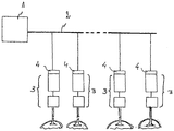
- the management system comprises a motor control unit 1 connected to a communication bus, here a serial bus 2, to which are connected valve actuators 3.
- the control unit 1 comprises, in a manner known per se, a calculator associated with a memory comprising mapping data of the opening and closing angles of the valves as a function, in particular, of the speed and the engine load, the modes of movement of the valves (switching or ballistics) ...
- the engine control unit is also connected to detection devices of the engine speed, the engine load, temperatures ... and to other components of the engine such as injectors, spark plugs, cooling system ...
- the bus 2 is here a CAN bus type (for "Controller Area Network")
- the actuators 3 comprise, in a manner known per se, a control circuit connected to a power circuit which is itself connected to attraction coils of an actuating member for the valves towards two extreme positions respectively corresponding to the open position. of the valve and the closed position of the valve.
- Each actuator 3 is provided with a connection interface 4 to the bus 2 allowing the control circuit of the actuator to receive frames sent to it by the engine control unit 1 and to return frames to the control unit. motor control 1.
- Each actuator 3 associated with a connection interface 4 constitutes an assembly with which the motor control unit 1 communicates.
- the engine control unit 1 is thus arranged to transmit to each actuator 3 frames having steering instructions of the actuator 3 on two crankshaft laps (these instructions include the opening and closing angles of the valves, the mode of movement %) and information on engine operating parameters such as engine speed, coolant temperature, etc.
- the assembly formed by the control circuit of the actuator 3 and the connection interface 4 is arranged to receive a frame sent to it by the engine control unit 1, to extract from the frame the control instructions and control the power circuit of the actuator according to the received steering instructions and to send back to the engine control unit 1 a frame including diagnostic information of the actuator such as the opening angles and closing valves actually applied, the temperature of the actuator, the voltage within the actuator ... and other such information which may in particular reveal a malfunction for example of the actuator.
- the engine control unit 1 On receipt of the frames from these sets, the engine control unit 1 analyzes the information received in particular to verify that one of them is not indicative of a failure likely ultimately cause a general malfunction of the motor. If necessary, the engine control unit 1 may decide to stop the faulty actuator.
- the actuators are assigned to groups and that, when an actuator of a group is defective, the control unit stops all the actuators of the group. It goes without saying that the fewer groups will include actuators, the less their conviction will be penalizing for the operation of the engine.
- the actuators are operably or logically grouped within the engine control unit 1 per cylinder.
- Each frame sent by the engine control unit 1 thus contains steering instructions and information concerning the actuator or the actuators of a cylinder.
- the engine control unit When one of the actuators of a cylinder is defective, the engine control unit no longer sends frames to the actuator (s) of this cylinder.
- the heat engine having at least two cylinders may nevertheless continue to operate at least to allow the vehicle to reach the place where it will be repaired.
- the grouping by cylinder also facilitates the adaptation of the management system to engines with different numbers of cylinders.
- control assemblies comprising a single actuator
- such an assembly can group two or more actuators, it being understood that it is necessary that there be at least two sets.
Landscapes
- Engineering & Computer Science (AREA)
- Mechanical Engineering (AREA)
- General Engineering & Computer Science (AREA)
- Chemical & Material Sciences (AREA)
- Combustion & Propulsion (AREA)
- Valve Device For Special Equipments (AREA)
- Output Control And Ontrol Of Special Type Engine (AREA)
- Combined Controls Of Internal Combustion Engines (AREA)
Description
- La présente invention concerne un système de gestion d'un moteur thermique à soupapes tel qu'un moteur multicylindre à quatre temps d'un véhicule automobile.
- Un tel système de gestion comprend une unité de contrôle moteur (ou ECU pour "Engine Control Unit") reliée par un bus série à une unité de contrôle de soupapes (ou VCU pour "Valve Control Unit") elle-même reliée à des actionneurs électromagnétiques de soupapes. L'unité de contrôle moteur est agencée pour définir, en fonction notamment du régime et de la charge du moteur, des instructions de commande de soupapes qu'elle transmet sur le bus série dans une trame unique avec des informations relatives au fonctionnement du moteur tel que le régime moteur et sa température. Les instructions de commande comprennent des modes de déplacement des soupapes, des angles d'ouverture et des angles de fermeture de celles-ci. L'unité de contrôle de soupapes reçoit cette trame et élabore, à partir des instructions de commande contenues dans la trame, des consignes de pilotage des soupapes qu'elle transmet individuellement à chaque actionneur de soupape. L'architecture de ce système rend difficile pour les constructeurs son adaptation à différents types de moteur, plus particulièrement lorsque le nombre de cylindres est différent d'un moteur à l'autre. Ceci suppose en effet de reprogrammer l'unité de contrôle moteur et de changer l'unité de contrôle de soupapes pour un modèle adapté au nombre d'actionneurs à commander. En outre, l'unité de commande de soupapes renvoie à l'unité de contrôle moteur une trame unique contenant d'une part des informations indiquant si les instructions de commandes ont été effectivement appliquées ou pas et, d'autre part, des informations relatives au fonctionnement de l'unité de contrôle de soupapes. Avec cette architecture du système de gestion, il est difficile de faire remonter des informations individualisées sur le fonctionnement des actionneurs. Le document
US 6278932 décrit un système de gestion moteur ainsi que son procédé de fonctionnement. - Un but de l'invention est de proposer un système ayant une relativement bonne flexibilité permettant son adaptation à différentes configurations moteur ou à différentes méthodes de pilotage.
- A cet effet, on prévoit, selon l'invention, un système de gestion d'un moteur thermique à soupapes, selon la revendication 1.
- Ainsi, les actionneurs sont répartis en plusieurs ensembles directement reliés au bus de communication et l'unité de contrôle moteur transmet directement à ces ensembles les consignes de pilotage. La répartition est fonctionnelle (c'est-à-dire de préférence logique au sein de l'unité de commande) et n'est pas liée à la structure physique du système de gestion.
- De préférence, le moteur thermique comportant plusieurs cylindres ayant chacun au moins une soupape associée à un actionneur de soupape, chaque ensemble correspond à un cylindre. Ceci facilite l'adaptation du système de gestion à des moteurs ayant des nombres de cylin-dres différents. L'intervention nécessaire sur l'unité de contrôle moteur se limite à une relativement petite modification de la programmation.
- L'unité de contrôle moteur, qui pilote en général directement l'injecteur et la bougie (dans les moteurs à allumage commandé) associés à chaque cylindre, pilote aussi ici l'ensemble d'actionnement de ce cylindre.
- Il est ainsi possible de faire remonter à l'unité de contrôle moteur des informations précises relatives à chaque actionneur et notamment des angles réellement appliqués, des températures de fonctionnement, des tensions... de telle manière qu'en cas d'anomalie, l'unité de contrôle moteur puisse décider de condamner l'actionneur défectueux.
- D'autres caractéristiques et avantages de l'invention ressortiront à la lecture de la description qui suit d'un mode de réalisation particulier non limitatif de l'invention.
- Il sera fait référence à la figure unique annexée représentant schématiquement un système de gestion conforme à l'invention.
- En référence à la figure, le système de gestion conforme à l'invention comprend une unité de contrôle moteur 1 reliée à un bus de communication, ici un bus série 2, auquel sont reliés des actionneurs 3 de soupapes.
- L'unité de contrôle 1 comprend de façon connue en elle-même un calculateur associé à une mémoire comprenant des données de cartographie d'angles d'ouverture et de fermeture de soupapes en fonction notamment du régime et de la charge du moteur, de modes de déplacement des soupapes (commutation ou balistique)... L'unité de contrôle moteur est également reliée à des organes de détection du régime moteur, de la charge du moteur, de températures... et à d'autres composants du moteur thermique comme les injecteurs, les bougies, le système de refroidissement...
- Le bus 2 est ici un bus de type CAN (pour "Controller Area Network")
Les actionneurs 3 comportent de façon connue en soi un circuit de commande relié à un circuit de puissance lui-même relié à des bobines d'attraction d'un organe d'actionnement des soupapes vers deux positions extrêmes correspondant respectivement à la position d'ouverture de la soupape et à la position de fermeture de la soupape. - Chaque actionneur 3 est pourvu d'une interface de connexion 4 au bus 2 permettant au circuit de commande de l'actionneur de recevoir des trames émises à son intention par l'unité de contrôle moteur 1 et de renvoyer des trames à l'unité de contrôle moteur 1. Chaque actionneur 3 associé à une interface de connexion 4 constitue un ensemble avec lequel communique l'unité de contrôle moteur 1.
- L'unité de contrôle moteur 1 est ainsi agencée pour émettre à destination de chaque actionneur 3 des trames comportant des consignes de pilotage de l'actionneur 3 sur deux tours de vilebrequin (ces consignes comprennent les angles d'ouverture et de fermeture des soupapes, le mode de déplacement...) et des informations sur des paramètres de fonctionnement du moteur tels que le régime, la température de liquide de refroidissement...
- L'ensemble formé par le circuit de commande de l'actionneur 3 et l'interface de connexion 4 est agencé pour, à la réception d'une trame émise à son intention par l'unité de contrôle moteur 1, extraire de la trame les consignes de pilotage et commander le circuit de puissance de l'actionneur conformément aux consignes de pilotage reçues et pour renvoyer à l'unité de contrôle moteur 1 une trame comprenant des informations de diagnostic de l'actionneur telles que les angles d'ouverture et de fermeture réellement appliqués, la température de l'actionneur, la tension au sein de l'actionneur... et autres informations de ce type qui peuvent notamment révéler un disfonctionnement par exemple de l'actionneur.
- A la réception des trames provenant de ces ensembles, l'unité de contrôle moteur 1 analyse les informations reçues notamment pour vérifier que l'une d'entre elles n'est pas révélatrice d'une défaillance susceptible à terme d'entraîner un dysfonctionnement général du moteur. Le cas échéant, l'unité de contrôle moteur 1 peut décider de stopper l'actionneur défaillant.
- On peut prévoir qu'au sein de l'unité de contrôle moteur 1, les actionneurs soient affectés à des groupes et que, lorsqu'un actionneur d'un groupe est défaillant, l'unité de contrôle stoppe tous les actionneurs du groupe. Il va de soi que moins les groupes comporteront d'actionneurs, moins leur condamnation sera pénalisante pour le fonctionnement du moteur.
- De préférence, les actionneurs sont regroupés de façon fonctionnelle ou logique au sein de l'unité de contrôle moteur 1 par cylindre. Chaque trame envoyée par l'unité de contrôle moteur 1 contient ainsi des consignes de pilotage et des informations concernant l'actionneur ou les actionneurs d'un cylindre. Lorsqu'il y a plus d'un actionneur par cylindre, il est alors possible de prévoir un circuit de commande commun à tous les actionneurs d'un cylindre.
- Lorsque l'un des actionneurs d'un cylindre est défaillant, l'unité de contrôle moteur n'émet plus de trames à destination du ou des actionneurs de ce cylindre. Le moteur thermique comportant au moins deux cylindres peut néanmoins continuer à fonctionner au moins pour permettre au véhicule de rejoindre le lieu où il sera réparé.
- Le regroupement par cylindre facilite en outre l'adaptation du système de gestion à des moteurs comportant des nombres de cylindres différents.
- Bien entendu, l'invention n'est pas limitée au mode de réalisation décrit et on peut y apporter des variantes de réalisation sans sortir du cadre de l'invention tel que défini par les revendications.
- En particulier, bien que l'invention ait ici été décrite avec des ensembles de pilotage comprenant un seul actionneur, un tel ensemble peut regrouper deux actionneurs ou plus, étant entendu qu'il est nécessaire qu'il y ait au moins deux ensembles.
Claims (1)
- Système de gestion d'un moteur thermique à soupapes, comprenant une unité de contrôle moteur (1) et une pluralité d'actionneurs (3) de soupapes, l'unité de contrôle moteur étant reliée à un bus de communication (2) et les actionneurs étant répartis en au moins deux ensembles pourvus chacun d'une interface de connexion (4) de l'actionneur au bus de communication, l'unité de contrôle moteur étant agencée pour définir des consignes de pilotage des actionneurs et pour émettre dans le bus à destination de chaque ensemble une trame individualisée comportant les consignes de pilotage pour l'ensemble concerné, chaque actionneur (3) étant agencé pour émettre, dans le bus (2), à destination de l'unité de contrôle moteur (1), une trame comportant une valeur d'un paramètre de fonctionnement de l'actionneur,
caractérisé en ce que chaque ensemble formé par le circuit de commande de l'actionneur (3) et l'interface de connexion (4) est agencé pour, à la réception d'une trame émise à son intention par l'unité de contrôle moteur (1), extraire de la trame les consignes de pilotage et commander un circuit de puissance de l'actionneur conformément aux consignes de pilotage reçues, et pour renvoyer à l'unité de contrôle moteur (1) une trame comprenant des informations de diagnostic de l'actionneur,
et en ce que le moteur thermique comporte plusieurs cylindres ayant chacun au moins une soupape associée à un actionneur (3) de soupape, chaque ensemble correspond à un cylindre et chaque ensemble ne comportant qu'un actionneur (3) auquel l'interface de connexion (4) est reliée.
Applications Claiming Priority (3)
| Application Number | Priority Date | Filing Date | Title |
|---|---|---|---|
| FR0608374A FR2906298B1 (fr) | 2006-09-25 | 2006-09-25 | Systeme de commande de soupape a detection de defaillance |
| PCT/FR2007/001521 WO2008037871A2 (fr) | 2006-09-25 | 2007-09-19 | Systeme de commande de soupape a detection de defaillance |
| PCT/FR2007/001558 WO2008037889A1 (fr) | 2006-09-25 | 2007-09-25 | Procédé de commande individualisée d'ensemble d' actionneurs de soupapes par l'ecu |
Publications (2)
| Publication Number | Publication Date |
|---|---|
| EP2069613A1 EP2069613A1 (fr) | 2009-06-17 |
| EP2069613B1 true EP2069613B1 (fr) | 2019-11-13 |
Family
ID=38069382
Family Applications (2)
| Application Number | Title | Priority Date | Filing Date |
|---|---|---|---|
| EP07848255.1A Not-in-force EP2066876B1 (fr) | 2006-09-25 | 2007-09-19 | Systeme de commande de soupape a detection de defaillance |
| EP07848281.7A Active EP2069613B1 (fr) | 2006-09-25 | 2007-09-25 | Procédé de commande individualisée d'ensemble d'actionneurs de soupapes par l'ecu |
Family Applications Before (1)
| Application Number | Title | Priority Date | Filing Date |
|---|---|---|---|
| EP07848255.1A Not-in-force EP2066876B1 (fr) | 2006-09-25 | 2007-09-19 | Systeme de commande de soupape a detection de defaillance |
Country Status (5)
| Country | Link |
|---|---|
| US (2) | US8256391B2 (fr) |
| EP (2) | EP2066876B1 (fr) |
| JP (2) | JP2010504460A (fr) |
| FR (1) | FR2906298B1 (fr) |
| WO (1) | WO2008037871A2 (fr) |
Families Citing this family (3)
| Publication number | Priority date | Publication date | Assignee | Title |
|---|---|---|---|---|
| WO2010012870A1 (fr) * | 2008-07-30 | 2010-02-04 | Valeo Systemes De Controle Moteur | Unité de commande d'un ou plusieurs actionneurs électromagnétiques de soupape de moteur thermique, et différents ensembles de telles unités de commande et de tels actionneurs électromagnétiques |
| JP6297348B2 (ja) * | 2014-02-14 | 2018-03-20 | 西部電機株式会社 | バルブアクチュエータ通信システム、通信装置接続状態評価方法及びプログラム |
| SE2050229A1 (en) * | 2020-03-02 | 2021-08-17 | Freevalve Ab | Internal combustion engine comprising a decentralized valve-control arrangement and method therefore |
Family Cites Families (20)
| Publication number | Priority date | Publication date | Assignee | Title |
|---|---|---|---|---|
| FR2616481A1 (fr) * | 1987-06-12 | 1988-12-16 | Hamon Francois | Dispositif electronique de commande de soupapes de moteur a combustion interne et procedes de mise en oeuvre |
| JP2983232B2 (ja) * | 1989-11-07 | 1999-11-29 | 株式会社日立製作所 | 自律分散型エンジン制御装置 |
| JPH07317587A (ja) * | 1994-05-27 | 1995-12-05 | Nippondenso Co Ltd | 車両用内燃機関の制御装置 |
| JP3517969B2 (ja) * | 1994-08-25 | 2004-04-12 | 株式会社デンソー | 車両用電子制御装置 |
| JPH1047028A (ja) * | 1996-07-31 | 1998-02-17 | Suzuki Motor Corp | 電磁弁型エンジンの制御装置 |
| JP3454116B2 (ja) * | 1997-11-10 | 2003-10-06 | トヨタ自動車株式会社 | 車両用駆動装置 |
| DE19756095C2 (de) * | 1997-12-17 | 2001-11-22 | Telefunken Microelectron | Vorrichtung zum Betrieb von Aktoren zur elektromagnetischen Ventilsteuerung bei Brennkraftmaschinen |
| DE19756342C2 (de) * | 1997-12-18 | 2003-02-13 | Conti Temic Microelectronic | Verfahren zur Steuerung einer Brennkraftmaschine |
| JPH11294209A (ja) * | 1998-04-10 | 1999-10-26 | Toyota Motor Corp | 電磁弁の制御装置 |
| JP2000154740A (ja) * | 1998-11-19 | 2000-06-06 | Nissan Motor Co Ltd | 可変動弁エンジンの制御装置 |
| DE50000537D1 (de) * | 1999-04-21 | 2002-10-24 | Siemens Ag | Steuerungsanlage für eine brennkraftmaschine mit elektromechanisch betätigten gaswechselventilen |
| DE19918094A1 (de) * | 1999-04-21 | 2000-11-02 | Siemens Ag | Steueranlage und Verfahren zum Betrieb einer Brennkraftmaschine |
| DE19918032C1 (de) * | 1999-04-21 | 2000-11-16 | Siemens Ag | Schaltung zur Laststeuerung und Verfahren zum Notlaufbetrieb einer Brennkraftmaschine |
| JP3395724B2 (ja) * | 1999-08-10 | 2003-04-14 | 住友金属工業株式会社 | ダイオキシン類汚染物質の無害化処理方法 |
| JP2001152882A (ja) * | 1999-11-25 | 2001-06-05 | Denso Corp | 内燃機関の電磁駆動バルブの異常診断装置 |
| JP3692888B2 (ja) * | 2000-02-04 | 2005-09-07 | 日産自動車株式会社 | 電磁駆動弁の制御装置 |
| JP2002221012A (ja) | 2001-01-23 | 2002-08-09 | Auto Network Gijutsu Kenkyusho:Kk | エンジンモジュール |
| DE10335905B4 (de) * | 2003-08-06 | 2018-07-05 | Robert Bosch Gmbh | Verfahren und Vorrichtung zur bidirektionalen Eindraht-Datenübertragung |
| US7055483B2 (en) * | 2004-03-19 | 2006-06-06 | Ford Global Technologies, Llc | Quick starting engine with electromechanical valves |
| GB0422951D0 (en) * | 2004-10-15 | 2004-11-17 | Rolls Royce Plc | Electrical control systems |
-
2006
- 2006-09-25 FR FR0608374A patent/FR2906298B1/fr not_active Expired - Fee Related
-
2007
- 2007-09-19 JP JP2009528753A patent/JP2010504460A/ja active Pending
- 2007-09-19 US US12/441,675 patent/US8256391B2/en not_active Expired - Fee Related
- 2007-09-19 WO PCT/FR2007/001521 patent/WO2008037871A2/fr not_active Ceased
- 2007-09-19 EP EP07848255.1A patent/EP2066876B1/fr not_active Not-in-force
- 2007-09-25 EP EP07848281.7A patent/EP2069613B1/fr active Active
- 2007-09-25 US US12/441,850 patent/US8116964B2/en not_active Expired - Fee Related
- 2007-09-25 JP JP2009528760A patent/JP5363323B2/ja not_active Expired - Fee Related
Non-Patent Citations (1)
| Title |
|---|
| None * |
Also Published As
| Publication number | Publication date |
|---|---|
| EP2066876A2 (fr) | 2009-06-10 |
| FR2906298A1 (fr) | 2008-03-28 |
| FR2906298B1 (fr) | 2008-12-26 |
| WO2008037871A3 (fr) | 2008-05-22 |
| US20090276146A1 (en) | 2009-11-05 |
| JP2010504460A (ja) | 2010-02-12 |
| EP2066876B1 (fr) | 2016-03-23 |
| US8116964B2 (en) | 2012-02-14 |
| EP2069613A1 (fr) | 2009-06-17 |
| US20100018481A1 (en) | 2010-01-28 |
| US8256391B2 (en) | 2012-09-04 |
| JP5363323B2 (ja) | 2013-12-11 |
| WO2008037871A2 (fr) | 2008-04-03 |
| JP2010504461A (ja) | 2010-02-12 |
Similar Documents
| Publication | Publication Date | Title |
|---|---|---|
| US7610903B2 (en) | Multicylinder internal combustion engine | |
| US20060130814A1 (en) | Variable incremental activation and deactivation of cylinders in a displacement on demand engine | |
| DE102008013766A1 (de) | System zur Detektion von Lecks eines hydraulischen Fluids | |
| TW360739B (en) | Arrangement and method for the valve control of a reversible diesel combustion engine | |
| EP2069613A1 (fr) | Procédé de commande individualisée d'ensemble d' actionneurs de soupapes par l'ecu | |
| US8205599B2 (en) | System and method for cleaning solenoid valve debris | |
| WO2008037889A1 (fr) | Procédé de commande individualisée d'ensemble d' actionneurs de soupapes par l'ecu | |
| EP0618998B1 (fr) | Systeme de controle moteur a corps de papillon motorise | |
| US7918130B2 (en) | Methods and systems to identify cam phaser hardware degradation | |
| US8620560B2 (en) | Internal combustion engine control device | |
| EP3132133B1 (fr) | Moteur à combustion interne avec un système de pompe à carburant à injection directe à course variable et procédé pour contrôler le moteur | |
| US7654236B2 (en) | Method and device for controlling an internal combustion engine | |
| WO2005086762A3 (fr) | Systeme de commande de reglage des soupapes d'un moteur avec desactivation des cylindres | |
| US20050029869A1 (en) | Controlled vehicle shutdown system | |
| JP7238395B2 (ja) | 内燃機関 | |
| CN103204154B (zh) | 用于故障检测的燃料切断和混合动力操作的协调 | |
| US20070079781A1 (en) | Procedure to operate an internal combustion engine with an electrohydraulic valve control | |
| FR3068728B1 (fr) | Procede de pilotage electronique d’actionneurs de soupapes d’un moteur thermique | |
| EP2957752A1 (fr) | Dispositif complémentaire pour modifier le réglage des paramètres d'un moteur à combustion interne d'un véhicule | |
| US20090071422A1 (en) | Electronic valve system | |
| US12553399B2 (en) | Torsional vibration solutions for cylinder deactivation | |
| CN202500630U (zh) | 发动机配气控制系统和汽车 | |
| US12326122B2 (en) | Method for diagnosing a part of a powertrain system | |
| JPH09242591A (ja) | 車両の制御装置 | |
| CN119737240A (zh) | 航空发动机电喷控制器的双冗余控制方法及系统 |
Legal Events
| Date | Code | Title | Description |
|---|---|---|---|
| PUAI | Public reference made under article 153(3) epc to a published international application that has entered the european phase |
Free format text: ORIGINAL CODE: 0009012 |
|
| 17P | Request for examination filed |
Effective date: 20090304 |
|
| AK | Designated contracting states |
Kind code of ref document: A1 Designated state(s): AT BE BG CH CY CZ DE DK EE ES FI FR GB GR HU IE IS IT LI LT LU LV MC MT NL PL PT RO SE SI SK TR |
|
| AX | Request for extension of the european patent |
Extension state: AL BA HR MK RS |
|
| 17Q | First examination report despatched |
Effective date: 20090721 |
|
| DAX | Request for extension of the european patent (deleted) | ||
| STAA | Information on the status of an ep patent application or granted ep patent |
Free format text: STATUS: EXAMINATION IS IN PROGRESS |
|
| GRAP | Despatch of communication of intention to grant a patent |
Free format text: ORIGINAL CODE: EPIDOSNIGR1 |
|
| STAA | Information on the status of an ep patent application or granted ep patent |
Free format text: STATUS: GRANT OF PATENT IS INTENDED |
|
| GRAS | Grant fee paid |
Free format text: ORIGINAL CODE: EPIDOSNIGR3 |
|
| INTG | Intention to grant announced |
Effective date: 20181114 |
|
| RIN1 | Information on inventor provided before grant (corrected) |
Inventor name: GELEZ, NICOLAS Inventor name: DANIOUX, RONAN Inventor name: BOUCHEZ, BORIS |
|
| GRAA | (expected) grant |
Free format text: ORIGINAL CODE: 0009210 |
|
| STAA | Information on the status of an ep patent application or granted ep patent |
Free format text: STATUS: THE PATENT HAS BEEN GRANTED |
|
| AK | Designated contracting states |
Kind code of ref document: B1 Designated state(s): AT BE BG CH CY CZ DE DK EE ES FI FR GB GR HU IE IS IT LI LT LU LV MC MT NL PL PT RO SE SI SK TR |
|
| REG | Reference to a national code |
Ref country code: GB Ref legal event code: FG4D Free format text: NOT ENGLISH |
|
| REG | Reference to a national code |
Ref country code: CH Ref legal event code: EP Ref country code: AT Ref legal event code: REF Ref document number: 1201877 Country of ref document: AT Kind code of ref document: T Effective date: 20191115 |
|
| REG | Reference to a national code |
Ref country code: DE Ref legal event code: R096 Ref document number: 602007059503 Country of ref document: DE |
|
| REG | Reference to a national code |
Ref country code: IE Ref legal event code: FG4D Free format text: LANGUAGE OF EP DOCUMENT: FRENCH |
|
| REG | Reference to a national code |
Ref country code: NL Ref legal event code: MP Effective date: 20191113 |
|
| REG | Reference to a national code |
Ref country code: LT Ref legal event code: MG4D |
|
| PG25 | Lapsed in a contracting state [announced via postgrant information from national office to epo] |
Ref country code: LV Free format text: LAPSE BECAUSE OF FAILURE TO SUBMIT A TRANSLATION OF THE DESCRIPTION OR TO PAY THE FEE WITHIN THE PRESCRIBED TIME-LIMIT Effective date: 20191113 Ref country code: SE Free format text: LAPSE BECAUSE OF FAILURE TO SUBMIT A TRANSLATION OF THE DESCRIPTION OR TO PAY THE FEE WITHIN THE PRESCRIBED TIME-LIMIT Effective date: 20191113 Ref country code: NL Free format text: LAPSE BECAUSE OF FAILURE TO SUBMIT A TRANSLATION OF THE DESCRIPTION OR TO PAY THE FEE WITHIN THE PRESCRIBED TIME-LIMIT Effective date: 20191113 Ref country code: LT Free format text: LAPSE BECAUSE OF FAILURE TO SUBMIT A TRANSLATION OF THE DESCRIPTION OR TO PAY THE FEE WITHIN THE PRESCRIBED TIME-LIMIT Effective date: 20191113 Ref country code: ES Free format text: LAPSE BECAUSE OF FAILURE TO SUBMIT A TRANSLATION OF THE DESCRIPTION OR TO PAY THE FEE WITHIN THE PRESCRIBED TIME-LIMIT Effective date: 20191113 Ref country code: FI Free format text: LAPSE BECAUSE OF FAILURE TO SUBMIT A TRANSLATION OF THE DESCRIPTION OR TO PAY THE FEE WITHIN THE PRESCRIBED TIME-LIMIT Effective date: 20191113 Ref country code: BG Free format text: LAPSE BECAUSE OF FAILURE TO SUBMIT A TRANSLATION OF THE DESCRIPTION OR TO PAY THE FEE WITHIN THE PRESCRIBED TIME-LIMIT Effective date: 20200213 Ref country code: PL Free format text: LAPSE BECAUSE OF FAILURE TO SUBMIT A TRANSLATION OF THE DESCRIPTION OR TO PAY THE FEE WITHIN THE PRESCRIBED TIME-LIMIT Effective date: 20191113 Ref country code: GR Free format text: LAPSE BECAUSE OF FAILURE TO SUBMIT A TRANSLATION OF THE DESCRIPTION OR TO PAY THE FEE WITHIN THE PRESCRIBED TIME-LIMIT Effective date: 20200214 Ref country code: PT Free format text: LAPSE BECAUSE OF FAILURE TO SUBMIT A TRANSLATION OF THE DESCRIPTION OR TO PAY THE FEE WITHIN THE PRESCRIBED TIME-LIMIT Effective date: 20200313 |
|
| PG25 | Lapsed in a contracting state [announced via postgrant information from national office to epo] |
Ref country code: IS Free format text: LAPSE BECAUSE OF FAILURE TO SUBMIT A TRANSLATION OF THE DESCRIPTION OR TO PAY THE FEE WITHIN THE PRESCRIBED TIME-LIMIT Effective date: 20200313 |
|
| PG25 | Lapsed in a contracting state [announced via postgrant information from national office to epo] |
Ref country code: CZ Free format text: LAPSE BECAUSE OF FAILURE TO SUBMIT A TRANSLATION OF THE DESCRIPTION OR TO PAY THE FEE WITHIN THE PRESCRIBED TIME-LIMIT Effective date: 20191113 Ref country code: RO Free format text: LAPSE BECAUSE OF FAILURE TO SUBMIT A TRANSLATION OF THE DESCRIPTION OR TO PAY THE FEE WITHIN THE PRESCRIBED TIME-LIMIT Effective date: 20191113 Ref country code: DK Free format text: LAPSE BECAUSE OF FAILURE TO SUBMIT A TRANSLATION OF THE DESCRIPTION OR TO PAY THE FEE WITHIN THE PRESCRIBED TIME-LIMIT Effective date: 20191113 Ref country code: EE Free format text: LAPSE BECAUSE OF FAILURE TO SUBMIT A TRANSLATION OF THE DESCRIPTION OR TO PAY THE FEE WITHIN THE PRESCRIBED TIME-LIMIT Effective date: 20191113 |
|
| REG | Reference to a national code |
Ref country code: DE Ref legal event code: R097 Ref document number: 602007059503 Country of ref document: DE |
|
| REG | Reference to a national code |
Ref country code: AT Ref legal event code: MK05 Ref document number: 1201877 Country of ref document: AT Kind code of ref document: T Effective date: 20191113 |
|
| PG25 | Lapsed in a contracting state [announced via postgrant information from national office to epo] |
Ref country code: SK Free format text: LAPSE BECAUSE OF FAILURE TO SUBMIT A TRANSLATION OF THE DESCRIPTION OR TO PAY THE FEE WITHIN THE PRESCRIBED TIME-LIMIT Effective date: 20191113 |
|
| PLBE | No opposition filed within time limit |
Free format text: ORIGINAL CODE: 0009261 |
|
| STAA | Information on the status of an ep patent application or granted ep patent |
Free format text: STATUS: NO OPPOSITION FILED WITHIN TIME LIMIT |
|
| 26N | No opposition filed |
Effective date: 20200814 |
|
| REG | Reference to a national code |
Ref country code: DE Ref legal event code: R079 Ref document number: 602007059503 Country of ref document: DE Free format text: PREVIOUS MAIN CLASS: F01L0009040000 Ipc: F01L0009200000 |
|
| PG25 | Lapsed in a contracting state [announced via postgrant information from national office to epo] |
Ref country code: AT Free format text: LAPSE BECAUSE OF FAILURE TO SUBMIT A TRANSLATION OF THE DESCRIPTION OR TO PAY THE FEE WITHIN THE PRESCRIBED TIME-LIMIT Effective date: 20191113 Ref country code: SI Free format text: LAPSE BECAUSE OF FAILURE TO SUBMIT A TRANSLATION OF THE DESCRIPTION OR TO PAY THE FEE WITHIN THE PRESCRIBED TIME-LIMIT Effective date: 20191113 |
|
| PG25 | Lapsed in a contracting state [announced via postgrant information from national office to epo] |
Ref country code: IT Free format text: LAPSE BECAUSE OF FAILURE TO SUBMIT A TRANSLATION OF THE DESCRIPTION OR TO PAY THE FEE WITHIN THE PRESCRIBED TIME-LIMIT Effective date: 20191113 |
|
| PG25 | Lapsed in a contracting state [announced via postgrant information from national office to epo] |
Ref country code: MC Free format text: LAPSE BECAUSE OF FAILURE TO SUBMIT A TRANSLATION OF THE DESCRIPTION OR TO PAY THE FEE WITHIN THE PRESCRIBED TIME-LIMIT Effective date: 20191113 |
|
| REG | Reference to a national code |
Ref country code: CH Ref legal event code: PL |
|
| GBPC | Gb: european patent ceased through non-payment of renewal fee |
Effective date: 20200925 |
|
| REG | Reference to a national code |
Ref country code: BE Ref legal event code: MM Effective date: 20200930 |
|
| PG25 | Lapsed in a contracting state [announced via postgrant information from national office to epo] |
Ref country code: LU Free format text: LAPSE BECAUSE OF NON-PAYMENT OF DUE FEES Effective date: 20200925 |
|
| PG25 | Lapsed in a contracting state [announced via postgrant information from national office to epo] |
Ref country code: CH Free format text: LAPSE BECAUSE OF NON-PAYMENT OF DUE FEES Effective date: 20200930 Ref country code: BE Free format text: LAPSE BECAUSE OF NON-PAYMENT OF DUE FEES Effective date: 20200930 Ref country code: IE Free format text: LAPSE BECAUSE OF NON-PAYMENT OF DUE FEES Effective date: 20200925 Ref country code: GB Free format text: LAPSE BECAUSE OF NON-PAYMENT OF DUE FEES Effective date: 20200925 Ref country code: LI Free format text: LAPSE BECAUSE OF NON-PAYMENT OF DUE FEES Effective date: 20200930 |
|
| PGFP | Annual fee paid to national office [announced via postgrant information from national office to epo] |
Ref country code: FR Payment date: 20210921 Year of fee payment: 15 |
|
| PGFP | Annual fee paid to national office [announced via postgrant information from national office to epo] |
Ref country code: DE Payment date: 20210930 Year of fee payment: 15 |
|
| PG25 | Lapsed in a contracting state [announced via postgrant information from national office to epo] |
Ref country code: TR Free format text: LAPSE BECAUSE OF FAILURE TO SUBMIT A TRANSLATION OF THE DESCRIPTION OR TO PAY THE FEE WITHIN THE PRESCRIBED TIME-LIMIT Effective date: 20191113 Ref country code: MT Free format text: LAPSE BECAUSE OF FAILURE TO SUBMIT A TRANSLATION OF THE DESCRIPTION OR TO PAY THE FEE WITHIN THE PRESCRIBED TIME-LIMIT Effective date: 20191113 Ref country code: CY Free format text: LAPSE BECAUSE OF FAILURE TO SUBMIT A TRANSLATION OF THE DESCRIPTION OR TO PAY THE FEE WITHIN THE PRESCRIBED TIME-LIMIT Effective date: 20191113 |
|
| REG | Reference to a national code |
Ref country code: DE Ref legal event code: R119 Ref document number: 602007059503 Country of ref document: DE |
|
| PG25 | Lapsed in a contracting state [announced via postgrant information from national office to epo] |
Ref country code: FR Free format text: LAPSE BECAUSE OF NON-PAYMENT OF DUE FEES Effective date: 20220930 Ref country code: DE Free format text: LAPSE BECAUSE OF NON-PAYMENT OF DUE FEES Effective date: 20230401 |