EP2067899A1 - Rütteleinrichtung - Google Patents
Rütteleinrichtung Download PDFInfo
- Publication number
- EP2067899A1 EP2067899A1 EP08170699A EP08170699A EP2067899A1 EP 2067899 A1 EP2067899 A1 EP 2067899A1 EP 08170699 A EP08170699 A EP 08170699A EP 08170699 A EP08170699 A EP 08170699A EP 2067899 A1 EP2067899 A1 EP 2067899A1
- Authority
- EP
- European Patent Office
- Prior art keywords
- spring
- vibrating device
- coil spring
- coil
- elastic element
- Prior art date
- Legal status (The legal status is an assumption and is not a legal conclusion. Google has not performed a legal analysis and makes no representation as to the accuracy of the status listed.)
- Granted
Links
Images



Classifications
-
- E—FIXED CONSTRUCTIONS
- E01—CONSTRUCTION OF ROADS, RAILWAYS, OR BRIDGES
- E01C—CONSTRUCTION OF, OR SURFACES FOR, ROADS, SPORTS GROUNDS, OR THE LIKE; MACHINES OR AUXILIARY TOOLS FOR CONSTRUCTION OR REPAIR
- E01C19/00—Machines, tools or auxiliary devices for preparing or distributing paving materials, for working the placed materials, or for forming, consolidating, or finishing the paving
- E01C19/22—Machines, tools or auxiliary devices for preparing or distributing paving materials, for working the placed materials, or for forming, consolidating, or finishing the paving for consolidating or finishing laid-down unset materials
- E01C19/30—Tamping or vibrating apparatus other than rollers ; Devices for ramming individual paving elements
- E01C19/34—Power-driven rammers or tampers, e.g. air-hammer impacted shoes for ramming stone-sett paving; Hand-actuated ramming or tamping machines, e.g. tampers with manually hoisted dropping weight
- E01C19/40—Power-driven rammers or tampers, e.g. air-hammer impacted shoes for ramming stone-sett paving; Hand-actuated ramming or tamping machines, e.g. tampers with manually hoisted dropping weight adapted to impart a smooth finish to the paving, e.g. tamping or vibrating finishers
- E01C19/407—Power-driven rammers or tampers, e.g. air-hammer impacted shoes for ramming stone-sett paving; Hand-actuated ramming or tamping machines, e.g. tampers with manually hoisted dropping weight adapted to impart a smooth finish to the paving, e.g. tamping or vibrating finishers with elements or parts partly or fully immersed in or penetrating into the material to act thereon, e.g. immersed vibrators or vibrating parts, kneading tampers, spaders
-
- E—FIXED CONSTRUCTIONS
- E01—CONSTRUCTION OF ROADS, RAILWAYS, OR BRIDGES
- E01C—CONSTRUCTION OF, OR SURFACES FOR, ROADS, SPORTS GROUNDS, OR THE LIKE; MACHINES OR AUXILIARY TOOLS FOR CONSTRUCTION OR REPAIR
- E01C19/00—Machines, tools or auxiliary devices for preparing or distributing paving materials, for working the placed materials, or for forming, consolidating, or finishing the paving
- E01C19/48—Machines, tools or auxiliary devices for preparing or distributing paving materials, for working the placed materials, or for forming, consolidating, or finishing the paving for laying-down the materials and consolidating them, or finishing the surface, e.g. slip forms therefor, forming kerbs or gutters in a continuous operation in situ
- E01C19/4833—Machines, tools or auxiliary devices for preparing or distributing paving materials, for working the placed materials, or for forming, consolidating, or finishing the paving for laying-down the materials and consolidating them, or finishing the surface, e.g. slip forms therefor, forming kerbs or gutters in a continuous operation in situ with tamping or vibrating means for consolidating or finishing, e.g. immersed vibrators, with or without non-vibratory or non-percussive pressing or smoothing means
- E01C19/4853—Apparatus designed for railless operation, e.g. crawler-mounted, provided with portable trackway arrangements
- E01C19/486—Apparatus designed for railless operation, e.g. crawler-mounted, provided with portable trackway arrangements with non-vibratory or non-percussive pressing or smoothing means; with supplemental elements penetrating the paving to work the material thereof
-
- F—MECHANICAL ENGINEERING; LIGHTING; HEATING; WEAPONS; BLASTING
- F16—ENGINEERING ELEMENTS AND UNITS; GENERAL MEASURES FOR PRODUCING AND MAINTAINING EFFECTIVE FUNCTIONING OF MACHINES OR INSTALLATIONS; THERMAL INSULATION IN GENERAL
- F16F—SPRINGS; SHOCK-ABSORBERS; MEANS FOR DAMPING VIBRATION
- F16F3/00—Spring units consisting of several springs, e.g. for obtaining a desired spring characteristic
- F16F3/08—Spring units consisting of several springs, e.g. for obtaining a desired spring characteristic with springs made of a material having high internal friction, e.g. rubber
- F16F3/10—Spring units consisting of several springs, e.g. for obtaining a desired spring characteristic with springs made of a material having high internal friction, e.g. rubber combined with springs made of steel or other material having low internal friction
- F16F3/12—Spring units consisting of several springs, e.g. for obtaining a desired spring characteristic with springs made of a material having high internal friction, e.g. rubber combined with springs made of steel or other material having low internal friction the steel spring being in contact with the rubber spring
Definitions
- the invention relates to a vibrating device for a construction machine according to the preamble of claim 1, or a self-propelled construction machine, in particular a slipform paver, according to claim 18.
- Slipform pavers are used in road, canal and airport construction. For example, they can produce road surfaces, gullies, curbs, and safety baffles for concrete roads.
- Previously known vibrating devices are commonly used in construction machines, in particular slipform pavers.
- Such a vibrating device has a housing, a vibration exciter disposed in the housing and a fastening device.
- the housing of the vibrating device is fastened to the construction machine with the aid of the fastening device, wherein the fastening device has at least one spring, in particular a helical spring, which transmits vibrations to the vibration exciter the construction machine as far as possible or completely prevented and thus decoupled the vibrator of the machine frame.
- the fastening device is at least partially immersed in the building material during operation.
- the disadvantage in the previously known vibrating devices that grains of the aggregates of the concrete can settle between the springs. These grains are increasingly surrounded by concrete until the springs become immobile by caking the concrete and the spring properties of the springs are deteriorated.
- the decoupling is ultimately repealed and the vibrations of the vibrator can be transferred to the machine frame. This can result in damage to the fastening device, the machine frame and in particular the vibrator.
- Object of the present invention is therefore to develop a vibrator of the type described above such that not deteriorate even after prolonged operation, the spring characteristics of the vibrator, no damage to the machine frame by the vibrations occur and the life of the vibrator is increased.
- the invention provides in an advantageous manner that in a vibrating device of the type described above, the spaces between the spring coils of the at least one coil spring are closed or filled by an elastic element inwardly.
- the spring properties of the at least one helical spring are adapted together with the elastic element to the vibration of the vibration exciter so that the transmission of vibrations of the vibration generator is largely or completely prevented on the machine frame.
- the elastic element can be made of an elastic plastic material such. As rubber, elastomer or the like.
- the embodiment has the advantage that no building material can settle in or on the coil springs. Thus, even if the fastener is immersed in the building material for a long time, the spring characteristics are maintained.
- the elastic member may be a molded part inserted into the coil spring.
- the molded part can be adapted to the inner contour of the coil spring, so that it can be screwed into the coil spring. This has the advantage that when disassembling the molding can be unscrewed from the coil spring again.
- the molding may have a cylindrical shape, wherein the diameter of the molding is equal to or slightly smaller than the inner diameter of the coil spring.
- the ends of the coil spring may be connected to frontally arranged mounting plates.
- the molded part can each have a projection on one or both front ends, wherein this projection engages in a recess of the fastening plate which is adapted to the projection or in a hexagon socket screw.
- the projections of the molding may consist of inserts which are introduced during the manufacture of the molding in the molding.
- the at least one coil spring may be encased on the outside by a layered elastic member which closes the interspaces between the spring coils inwardly.
- This layered elastic member may be a shrink film or a bellows.
- the arranged on the outside of the coil spring layered elastic element can be used in combination with the cylindrical molding.
- the coil spring may be completely surrounded by the elastic element substantially with the exception of the fastening device.
- the coil spring may be potted with the elastic material, wherein the spring coils of the coil spring are completely enclosed.
- a cavity may be arranged which extends along the helical spring axis and is open at the two end faces of the helical spring.
- the fastening device may comprise more than one, preferably four coil springs in another embodiment.
- the lower mounting plate may each have at least one opening between the points at which the coil springs are connected to the respective mounting plate.
- This at least one opening can be at least so large that an object that comes in between two adjacent coil springs in the interior space between the coil springs, the interior can leave through the opening again.
- the preferably four coil springs may be integrally enclosed by an elastic element, preferably encapsulated with this.
- the coil springs and the elastic element in this way form a one-piece spring assembly which can be attached as a unit to the mounting plates.
- the vibrating device described may be part of a self-propelled construction machine, in particular a slipform paver.
- Fig. 1 shows a part of a slipform paver.
- the slipform paver has an over the width of the slipform paver extending pressure pad 12, which extends parallel to the bottom 14 and extending transversely to the direction of travel 16.
- a height-adjustable side wall (not shown here) is arranged in each case.
- a plurality of vibrating devices 1 are arranged in series transversely to the direction of travel.
- the vibrator 1 is immersed in building material consisting of concrete 20 or a concrete mixture.
- Each vibrating device 1 has a housing 18, a vibration exciter 19 arranged in the housing 18 and a fastening device 10.
- the vibration generator 19 driven by, for example, an electric drive in conjunction with an imbalance mass vibrations.
- the imbalance mass can rotate at 12,000 rpm.
- the oscillation amplitude is very low, for example ⁇ 0.4 mm at the free end of the vibrator.
- the building material 20 is thereby liquefied and then brought by the pressure platen 12 in the desired shape.
- the vibrators 1 liquefy the building material in an area of action with a diameter of about 75 cm around the housing 18.
- the vibrators 1 are arranged so that overlap the vibrations of adjacent vibrators.
- the fastening device 10 secures the housing 18 of the vibrating device 1 to a pipe 25 connected to the machine frame 2 of the construction machine.
- the pipe 25 is height-adjustable by means of a piston-cylinder unit with respect to the machine frame.
- the tube 25 can be extended in width and adapted in this way the working width.
- the fastening device may alternatively be fastened to the pressure platen 12. So that the vibrations which the vibration exciter 19 performs are not transmitted to the machine frame 2 of the construction machine, the fastening device with a plurality of helical springs 8 is softer Spring characteristic provided.
- the coil springs 8 each have a plurality of spring coils. The spring characteristics of the coil springs 8 are matched to the vibrations of the vibration generator 19, so that the transmission of vibrations of the vibration generator 19 is largely or completely prevented on the construction machine.
- the fastener 10 with the coil springs 8 may be partially immersed in the concrete 20 during operation.
- Fig. 1 In the embodiment according to the invention in Fig. 1 are elastic elements 22, each consisting of molded parts introduced into the coil springs 8.
- the moldings are adapted to the inner contour of the respective coil spring 8, so that the spaces between the spring coils are closed inwards.
- the spring properties of the elastic elements are the coil springs 8 adapted so that the spring and damping properties of the fastening device 10 does not worsen or only insignificantly, so that further the transmission of vibrations of the vibrator 1 on the machine frame 2 of the construction machine is largely or completely prevented. Characterized in that the gaps between the spring coils of the coil springs 8 are filled, no grains, stones or the like can fix more to the coil springs 8, where the concrete 20 can agglomerate.
- each coil spring 8 is encapsulated with an elastic member 22 or surrounded by an elastic member which completely surrounds the spring coils of the coil spring 8. Inside each coil spring 8 is a cavity 38 which extends along the respective helical spring axis and is open at the two end faces of the respective helical spring 8.
- the coil springs 8 are fixed to the lower mounting plate 24 by means of screws 26 and nuts 28.
- the last spring winding of the coil spring 8 has a smaller diameter than the other spring windings of Coil springs 8 and this last spring coil is clamped between the head of a screw 26 and the lower mounting plate 24.
- the respective screws 26 are fastened with nuts 28.
- the coil springs 8 are fixed to the upper fixing plate 24, for example, by winding the respective last spring coil in the opposite direction, so that this last spring coil forms an eye-like opening. These last spring coils are clamped between the head of a screw 30 and the upper mounting plate 24. The screw 30 is also secured to the upper side of the second mounting plate 26 with a nut 32.
- a coil spring 8 is shown.
- the spaces between the spring coils of the coil spring 8 are closed by means of a tubular elastic element or molded part 22.
- the tubular elastic member 22 may be made of an elastic cloth or a sheet having a thickness of up to several millimeters.
- the tubular elastic member 22 may, for. B. be a shrink tube, which surrounds the outside of the coil spring 8.
- a bellows could be used.
- a cylindrical elastic molded part 22 could additionally be used in the interior of the coil spring 8.
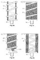
- Fig. 3b-3f show alternative embodiments of the elastic element 22nd Fig. 3b shows an inner sleeve whose outer diameter is equal to or slightly smaller than the inner diameter of the coil spring eighth
- Fig. 3c shows a coil spring with a molding.
- the molded part is adapted to the inner contour of the coil spring 8 and has a recess to receive the head of the screw 26.
- Fig. 3d shows a cylindrical molded part with an outer diameter which is equal to or slightly smaller than the inner diameter of the coil spring 8.
- the molded part has a projection 22a which corresponds to the hexagon socket of the Screw head is adapted and engages in this.
- the molding can be made Fig. 3c no recess and the molded part Fig. 3d have no projection. In this case, the mold parts would rest on the respective screw head of the screw 26.
- Fig. 3e shows a coil spring 8 in which the spring coils are encapsulated with an elastic member 22.
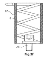
- Fig. 3f shows a coil spring 8, which is enclosed by an outer sleeve.
- This outer sleeve has an inner diameter which is equal to or slightly larger than the outer diameter of the coil spring eighth
- FIG. 4 and FIG. 5 show a side view and a plan view of a spring assembly 40, which consists of four coil springs 8, which are encapsulated with an elastic member 22.
- the spring coils at the respective ends of the coil springs 8 are rotated in the opposite direction so that they form eyelet-like openings 44.
- These eyelet-like openings 44 are located outside of the elastic material 22. Screws are used to clamp these eye-like last spring windings between the respective screw heads and the respective adjacent mounting plate 24. On the respective other side of the mounting plate 24 and the second mounting plate 26, the screws are screwed by means of nuts.
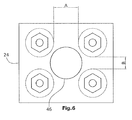
- FIG. 6 is a view of the lower bottom plate 24 Fig. 1 shown from the bottom.
- This lower bottom plate 24 has an opening 46 which has a diameter which is greater than the distance A, B between two adjacent coil springs 8. In this way, grains, which passes between the coil springs 8 passes into the interior space between the coil springs 8 are flushed out through the opening 46 again.
Landscapes
- Engineering & Computer Science (AREA)
- Architecture (AREA)
- Civil Engineering (AREA)
- Structural Engineering (AREA)
- General Engineering & Computer Science (AREA)
- Mechanical Engineering (AREA)
- Road Paving Machines (AREA)
- Vibration Prevention Devices (AREA)
Abstract
Description
- Die Erfindung betrifft eine Rütteleinrichtung für eine Baumaschine nach dem Oberbegriff des Anspruchs 1, bzw. eine selbstfahrende Baumaschine, insbesondere einen Gleitschalungsfertiger, nach Anspruch 18.
- Derartige Rütteleinrichtungen dienen in Gleitschalungsfertigern dazu, Beton zu verflüssigen und zu verdichten. Gleitschalungsfertiger werden im Straßen-, Kanal- und Flugplatzbau eingesetzt. Sie können beispielsweise Straßenbeläge, Wasserrinnen, Bordsteinprofile, und Sicherheits-Leitwände für Straßen aus Beton herstellen.
- Bisher bekannte Rütteleinrichtungen werden üblicherweise bei Baumaschinen, insbesondere Gleitschalungsfertigern verwendet. Eine solche Rütteleinrichtung weist ein Gehäuse, ein in dem Gehäuse angeordneten Schwingungserreger und eine Befestigungseinrichtung auf. Das Gehäuse der Rütteleinrichtung wird mit Hilfe der Befestigungseinrichtung an der Baumaschine befestigt, wobei die Befestigungseinrichtung mindestens eine Feder, insbesondere Schraubenfeder aufweist, die die Übertragung von Schwingungen des Schwingungserregers auf die Baumaschine weitestgehend oder vollständig verhindert und somit die Rütteleinrichtung von dem Maschinenrahmen entkoppelt.
- Bei den Rütteleinrichtungen ist es durchaus üblich, dass die Befestigungseinrichtung während des Betriebs zumindest teilweise in das Baumaterial eingetaucht ist. Dadurch besteht bei den bisher bekannten Rütteleinrichtungen der Nachteil, dass sich Körner der Zuschlagstoffe des Betons zwischen die Federn setzen können. Diese Körner werden zunehmend von Beton umgeben, bis die Federn durch das Festbacken des Beton unbeweglich werden und die Federeigenschaften der Federn verschlechtert werden. Dadurch ist die Entkopplung letztlich aufgehoben und die Schwingungen der Rütteleinrichtung können auf den Maschinenrahmen übertragen werden. Dies kann Schäden an der Befestigungseinrichtung, am Maschinenrahmen und insbesondere an der Rütteleinrichtung zur Folge haben.
- Aufgabe der vorliegenden Erfindung ist es daher, eine Rütteleinrichtung der eingangs beschriebenen Art derart weiterzubilden, dass sich auch nach längerer Betriebszeit die Federeigenschaften der Rütteleinrichtung nicht verschlechtern, keine Beschädigung des Maschinenrahmens durch die Schwingungen auftreten und die Standzeit der Rütteleinrichtung erhöht wird.
- Zur Lösung dieser Aufgabe dienen die Merkmale des Anspruchs 1.
- Die Erfindung sieht in vorteilhafte Weise vor, dass bei einer Rütteleinrichtung der eingangs beschriebenen Art die Zwischenräume zwischen den Federwicklungen der mindestens einen Schraubenfeder von einem elastischen Element nach innen verschlossen oder ausgefüllt sind. Die Federeigenschaften der mindestens einen Schraubenfeder sind gemeinsam mit dem elastischen Element derart an die Schwingung des Schwingungserregers angepasst, dass die Übertragung von Schwingungen des Schwingungserregers auf den Maschinenrahmen weitestgehend oder vollständig verhindert ist. Das elastische Element kann aus einer elastischen Kunststoffmasse wie z. B. Gummi, Elastomer oder Ähnlichem bestehen.
- Die Ausführungsform hat den Vorteil, dass sich kein Baumaterial in bzw. an den Schraubenfedern festsetzen kann. Damit bleiben die Federeigenschaften, auch wenn die Befestigungseinrichtung für längere Zeit in dem Baumaterial eingetaucht ist, erhalten.
- Das elastische Element kann ein Formteil sein, das in die Schraubenfeder eingesetzt ist. Das Formteil kann der Innenkontur der Schraubenfeder angepasst sein, so dass es in die Schraubenfeder eingedreht werden kann. Dies hat den Vorteil, dass bei einer Demontage das Formteil wieder aus der Schraubenfeder herausgedreht werden kann.
- Alternativ kann dass Formteil eine zylindrische Form aufweisen, wobei der Durchmesser des Formteils gleich oder geringfügig kleiner ist als der Innendurchmesser der Schraubenfeder.
- Die Enden der Schraubenfeder können mit stirnseitig angeordneten Befestigungsplatten verbunden sein. Das Formteil kann an einem oder beiden stirnseitigen Enden jeweils einen Vorsprung aufweisen, wobei dieser Vorsprung in eine dem Vorsprung angepasste Aussparung der Befestigungsplatte oder in eine Innensechskantschraube eingreift. Die Vorsprünge des Formteils können aus Einlegeteilen bestehen, die während der Fertigung des Formteils in das Formteil eingebracht werden.
- Die mindestens eine Schraubenfeder kann auf der Außenseite von einem schichtförmigen elastischen Element ummantelt sein, das die Zwischenräume zwischen den Federwicklungen nach innen verschließt. Dieses schichtförmige elastische Element kann eine Schrumpffolie oder einen Faltenbalg sein. Auch kann das auf der Außenseite der Schraubenfeder angeordnete schichtförmige elastische Element in Kombination mit dem zylindrischen Formteil verwendet werden.
- Bei einem weiteren Ausführungsbeispiel kann die Schraubenfeder von dem elastischen Element im Wesentlichen mit Ausnahme der Befestigungseinrichtung vollständig umgeben sein. Die Schraubenfeder kann mit dem elastischen Werkstoff vergossen sein, wobei die Federwicklungen der Schraubenfeder vollständig umschlossen sind.
- Im Inneren der mindestens einen Schraubenfeder kann ein Hohlraum angeordnet sein, der sich entlang der Schraubenfederachse erstreckt und an den beiden Stirnseiten der Schraubenfeder offen ist.
- Dies hat den Vorteil, dass die Schraubenfedern leichter an den Befiestigungspiatten zu befestigen sind.
- Die Befestigungseinrichtung kann bei einem weiteren Ausführungsbeispiel mehr als eine, vorzugsweise vier Schraubenfedern aufweisen.
- Die Befiestigungsplatten, insbesondere die untere Befestigungsplatte kann zwischen den Stellen, an denen die Schraubenfedern mit der jeweiligen Befestigungsplatte verbunden sind, jeweils mindestens eine Öffnung aufweisen. Diese mindestens eine Öffnung kann zumindest so groß sein, dass ein Gegenstand, der zwischen zwei benachbarten Schraubenfedern in den Innenraum zwischen den Schraubenfedern hineingelangt, den Innenraum durch die Öffnung wieder verlassen kann.
- Dies hat den Vorteil, dass Gegenstände, wie zum Beispiel Steine, die durch die Schraubenfedern hindurch gelangen, durch die Öffnungen wieder heraus gespült werden können.
- Die vorzugsweise vier Schraubenfedern können einstückig von einem elastischen Element umschlossen, vorzugsweise mit diesem vergossen sein. Die Schraubenfedern und das elastische Element bilden auf diese Weise ein einstückiges Federpaket, das als Einheit an den Befestigungsplatten befestigt werden kann.
- Die beschriebene Rütteleinrichtung kann Bestandteil einer selbstfahrenden Baumaschine, insbesondere eines Gleitschalungsfertigers sein.
- Im Folgenden werden unter Bezugnahme auf die Zeichnungen Ausführungsbeispiele der Erfindung näher erläutert. Es zeigen schematisch
- Fig. 1
- eine Seitenansicht auf einen Teil eines Gleitschalungsfertigers,
- Fig. 2
- eine Seitenansicht einer Rütteleinrichtung mit Befestigungseinrichtung eines Gleitschalungsfertigers,
- Fig. 3a
- eine Schraubenfeder mit einer elastischen Folie,
- Fig. 3b
- eine Schraubenfeder mit Innenhülse,
- Fig. 3c
- eine Schraubenfeder mit Formteil,
- Fig. 3d
- eine Schraubenfeder mit zylindrischem Formteil,
- Fig. 3e
- eine umspritzte Schraubenfeder,
- Fig. 3f
- eine Schraubenfeder mit Außenhülse,
- Fig. 4
- ein Schraubenfederpaket einer Befestigungseinrichtung,
- Fig. 5
- eine Draufsicht auf das Schraubenfederpaket aus
Fig. 4 , - Fig. 6
- eine Befestigungsplatte der Befestigungseinrichtung.
-
Fig. 1 zeigt einen Teil eines Gleitschalungsfertigers. Der Gleitschalungsfertiger weist eine sich über die Breite des Gleitschalungsfertigers erstreckende Druckbohle 12 auf, die parallel zum Boden 14 verläuft und sich quer zur Fahrtrichtung 16 erstreckt. An den seitlichen Enden der Druckbohle 12 ist jeweils eine hier nicht dargestellte höhenverstellbare Seitenwand angeordnet. In Fahrtrichtung 16 vor der Druckbohle 12 sind mehrere Rütteleinrichtungen 1 angeordnet. Diese Rütteleinrichtungen 1 sind in Reihe quer zur Fahrtrichtung angeordnet. Die Rütteleinrichtung 1 ist in Baumaterial, das aus Beton 20 oder aus einer Betonmischung besteht, eingetaucht. Jede Rütteleinrichtung 1 weist ein Gehäuse 18, einen in dem Gehäuse 18 angeordneten Schwingungserreger 19 und eine Befestigungseinrichtung 10 auf. Der Schwingungserreger 19 führt angetrieben durch beispielsweise einen elektrischen Antrieb in Verbindung mit einer Unwuchtmasse Schwingungen aus. Die Unwuchtmasse kann beispielsweise mit 12.000 U/min rotieren. Die Schwingungsamplitude ist dabei sehr gering, beispielsweise ± 0,4 mm am freien Ende der Rütteleinrichtung. Das Baumaterial 20 wird dadurch verflüssigt und dann durch die Druckbohle 12 in die gewünschte Form gebracht. Die Rütteleinrichtungen 1 verflüssigen das Baumaterial in einem Wirkungsbereich mit einem Durchmesser von ca. 75 cm um das Gehäuse 18. Die Rütteleinrichtungen 1 sind so angeordnet, dass sich die Schwingungen benachbarter Rütteleinrichtungen überschneiden. Die Befestigungseinrichtung 10 befestigt das Gehäuse 18 der Rütteleinrichtung 1 an einem mit dem Maschinenrahmen 2 der Baumaschine verbundenen Rohr 25. Das Rohr 25 ist mit Hilfe einer Kolben-Zylindereinheit im Bezug auf den Maschinenrahmen höhenverstellbar. Außerdem kann das Rohr 25 in der Breite verlängert werden und auf diese Weise der Arbeitsbreite angepasst werden. Die Befestigungseinrichtung kann alternativ an der Druckbohle 12 befestigt werden. Damit die Schwingungen, die der Schwingungserreger 19 ausführt nicht auf den Maschinenrahmen 2 der Baumaschine übertragen werden, ist die Befestigungseinrichtung mit mehreren Schraubenfedern 8 mit weicher Federcharakteristik versehen. Die Schraubenfedern 8 weisen jeweils mehrere Federwicklungen auf. Die Federeigenschaften der Schraubenfedern 8 sind auf die Schwingungen des Schwingungserregers 19 abgestimmt, so dass die Übertragung von Schwingungen des Schwingungserregers 19 auf die Baumaschine weitestgehend oder vollständig verhindert wird. Die Befestigungseinrichtung 10 mit den Schraubfedern 8 kann während des Betriebs zum Teil in den Beton 20 eingetaucht sein. - In dem erfindungsgemäßen Ausführungsbeispiel in
Fig. 1 sind elastische Elemente 22, die jeweils aus Formteilen bestehen in die Schraubenfedern 8 eingebracht. Die Formteile sind der Innenkontur der jeweiligen Schraubenfeder 8 angepasst, so dass die Zwischenräume zwischen den Federwicklungen nach innen verschlossen sind. Die Federeigenschaften der elastischen Elemente sind den Schraubenfedern 8 so angepasst, dass die Feder- und Dämpfungseigenschaften der Befestigungseinrichtung 10 sich nicht oder nur unwesentlich verschlechtern, so dass weiterhin die Übertragung von Schwingungen der Rütteleinrichtung 1 auf den Maschinenrahmen 2 der Baumaschine weitestgehend oder vollständig verhindert ist. Dadurch, dass die Zwischenräume zwischen den Federwicklungen der Schraubenfedern 8 ausgefüllt sind, können sich keine Körner, Steine oder Ähnliches mehr an den Schraubenfedern 8 festsetzen, an denen sich der Beton 20 agglomerieren kann. - In
Fig. 2 ist ein weiteres Ausführungsbeispiel dargestellt. Jede Schraubenfeder 8 ist mit einem elastischen Element 22 vergossen oder von einem elastischen Element umgeben, der die Federwicklungen der Schraubenfeder 8 vollständig umschließt. Im Inneren jeder Schraubenfeder 8 ist ein Hohlraum 38, der sich entlang der jeweiligen Schraubenfederachse erstreckt und an den beiden Stirnseiten der jeweiligen Schraubenfeder 8 offen ist. Die Schraubenfedern 8 sind an der unteren Befestigungsplatte 24 mit Hilfe von Schrauben 26 und Muttern 28 befestigt. Die letzte Federwicklung der Schraubenfeder 8 weist einen geringeren Durchmesser auf als die anderen Federwicklungen der Schraubenfedern 8 und diese letzte Federwicklung wird zwischen dem Kopf einer Schraube 26 und der unteren Befestigungsplatte 24 eingeklemmt. Auf der unteren Seite der unteren Befestigungsplatte 24 sind die jeweiligen Schrauben 26 mit Muttern 28 befestigt. Die Schraubenfedern 8 sind an der oberen Befestigungsplatte 24 beispielsweise dadurch befestigt, dass die jeweilige letzte Federwicklung in die entgegengesetzte Richtung gewickelt ist, sodass diese letzte Federwicklung eine ösenartige Öffnung bildet. Diese letzten Federwicklungen wird zwischen dem Kopf einer Schraube 30 und der oberen Befestigungsplatte 24 eingeklemmt. Die Schraube 30 ist auf der oberen Seite der zweiten Befestigungsplatte 26 ebenfalls mit einer Mutter 32 befestigt. - In
Fig. 3a ist eine Schraubenfeder 8 dargestellt. Die Zwischenräume zwischen den Federwicklungen der Schraubenfeder 8 sind mit Hilfe eines schlauchförmigen elastischen Element oder Formteil 22 verschlossen. Das schlauchförmige elastische Element 22 kann aus einem elastischen Stoff oder einer Folie mit einer Dicke von bis zu mehreren Millimetern sein. Das schlauchförmige elastische Element 22 kann z. B. ein Schrumpfschlauch sein, der die Außenseite der Schraubenfeder 8 ummantelt. Alternativ könnte auch ein Faltenbalg verwendet werden. In Kombination mit dem Schrumpfschlauch oder dem Faltenbalg könnte zusätzlich ein zylindrisches elastisches Formteil 22 im Inneren der Schraubenfeder 8 verwendet werden. -
Fig. 3b-3f zeigen alternative Ausführungsbeispiele für das elastische Element 22.Fig. 3b zeigt eine Innenhülse, deren Außendurchmesser gleich oder geringfügig kleiner ist als der Innendurchmesser der Schraubenfeder 8.Fig. 3c zeigt eine Schraubenfeder mit einem Formteil. Das Formteil ist der Innenkontur der Schraubenfeder 8 angepasst und weist eine Aussparung auf, um den Kopf der Schraube 26 aufzunehmen. Dieses Ausführungsbeispiel wurde bereits bei der Beschreibung zuFig. 1 näher erläutert.Fig. 3d zeigt ein zylindrisches Formteil mit einem Außendurchmesser, der gleich oder geringfügig kleiner ist als der Innendurchmesser der Schraubenfeder 8. Das Formteil weist einen Vorsprung 22a auf, der dem Innensechskant des Schraubenkopfs angepasst ist und in diesen eingreift. Alternativ kann das Formteil ausFig. 3c keine Aussparung und das Formteil ausFig. 3d keinen Vorsprung aufweisen. In diesem Fall würden die Formteile auf dem jeweiligen Schraubenkopf der Schraube 26 aufliegen. -
Fig. 3e zeigt eine Schraubenfeder 8 bei der die Federwicklungen mit einem elastischen Element 22 umgossen sind. Dieses Ausführungsbeispiel wurde bereits in der Beschreibung zuFig. 2 näher erläut.Fig. 3f zeigt eine Schraubenfeder 8, die von einer Außenhülse umschlossen ist. Diese Außenhülse weist einen Innendurchmesser auf, der gleich oder geringfügig größer ist als der Außendurchmesser der Schraubenfeder 8. -
Fig. 4 und Fig. 5 zeigen eine Seitenansicht und eine Draufsicht auf ein Federpaket 40, das aus vier Schraubenfedern 8 besteht, wobei diese mit einem elastischen Element 22 vergossen sind. Damit das Federpaket 40 an den Befestigungsplatten befestigt werden kann, sind die Federwicklungen an den jeweiligen Enden der Schraubenfedern 8 in die entgegengesetzte Richtung gedreht, sodass diese ösenartige Öffnungen 44 bilden. Diese ösenartigen Öffnungen 44 befinden sich außerhalb des elastischen Werkstoffs 22. Es werden Schrauben verwendet, um diese ösenartigen letzten Federwicklungen zwischen den jeweiligen Schraubenköpfen und der jeweiligen angrenzenden Befestigungsplatte 24 einzuklemmen. Auf der jeweiligen anderen Seite der Befestigungsplatte 24 bzw. der zweiten Befestigungsplatte 26 werden die Schrauben mit Hilfe von Muttern festgeschraubt. - In
Fig. 6 ist eine Ansicht der unteren Bodenplatte 24 ausFig. 1 von der Unterseite dargestellt. Diese untere Bodenplatte 24 weist eine Öffnung 46 auf, die einen Durchmesser besitzt, der größer ist als der Abstand A, B zwischen zwei benachbarten Schraubenfedern 8. Auf diese Weise können Körner, die zwischen den Schraubenfedern 8 hindurch in den Innenraum zwischen den Schraubenfedern 8 gelangt sind, durch die Öffnung 46 wieder ausgespült werden.
Claims (18)
- Rütteleinrichtung (1) für eine Baumaschine, insbesondere einen Gleitschalungsfertiger, mit- einem Gehäuse (18),- einem in dem Gehäuse (18) angeordneten Schwingungserreger (19) und- einer mit mindestens einer Schraubenfeder (8) mit mehreren Federwicklungen versehenen Befestigungseinrichtung (10) zum Befestigen des Gehäuses (18) an der Baumaschine,dadurch gekennzeichnet, dass
die Zwischenräume zwischen den Federwicklungen der mindestens einen Schraubenfeder (8) von einem elastischen Element (22) nach innen verschlossen oder zumindest teilweise ausgefüllt sind. - Rütteleinrichtung nach Anspruch 1, dadurch gekennzeichnet, dass die Federeigenschaften der mindestens einen Schraubenfeder (8) mit dem elastischen Element (22) gemeinsam derart an die Schwingungen des Schwingungserregers (19) angepasst sind, dass die Übertragung von Schwingungen des Schwingungserregers (19) auf den Maschinenrahmen (2) weitestgehend oder vollständig verhindert ist.
- Rütteleinrichtung (1) nach Anspruch 1 oder 2, dadurch gekennzeichnet, dass das elastische Element (22) aus einer elastischen Kunststoffmasse, insbesondere aus Gummi besteht.
- Rütteleinrichtung (1) nach einem der Ansprüche 1 bis 3, dadurch gekennzeichnet, dass das elastische Element (22) aus einem Formteil besteht, das in die Schraubenfeder (8) eingesetzt ist.
- Rütteleinrichtung (1) nach Anspruch 4, dadurch gekennzeichnet, dass das Formteil der Innenkontur der Schraubenfeder (8) angepasst ist.
- Rütteleinrichtung (1) nach Anspruch 4, dadurch gekennzeichnet, dass das Formteil eine zylindrische Form aufweist, wobei der Durchmesser des Formteils gleich oder geringfügig kleiner ist als der Innendurchmesser der Schraubenfeder (8).
- Rütteleinrichtung (1) nach einem der Ansprüche 4 bis 6, dadurch gekennzeichnet, dass die Enden der Schraubenfeder (8) mit stirnseitigen Befestigungsplatten (24) verbunden sind und dass das Formteil mindestens einen stirnseitigen Vorsprung aufweist, der in eine dem Vorsprung angepasste Aussparung der Befestigungsplatte (24) eingreift.
- Rütteleinrichtung (1) nach einem der Ansprüche 1 bis 7, dadurch gekennzeichnet, dass das elastische Element (22) eine Schlauchform aufweist, wobei das elastische Element (22) die mindestens eine Schraubenfeder (8) auf der Außenseite ummantelt und die Zwischenräume zwischen den Federwicklungen verschließt.
- Rütteleinrichtung (1) nach Anspruch 8, dadurch gekennzeichnet, dass das elastische Element (22) ein Schrumpfschlauch ist.
- Rütteleinrichtung (1) nach Anspruch 8, dadurch gekennzeichnet, dass das elastische Element (22) ein Faltenbalg ist.
- Rütteleinrichtung (1) nach einem der Ansprüche 1 bis 3, dadurch gekennzeichnet, dass die mindestens eine Schraubenfeder (8) von dem elastischen Elemente (22) im Wesentlichen vollständig umgeben ist.
- Rütteleinrichtung (1) nach Anspruch 11, dadurch gekennzeichnet, dass die mindestens eine Schraubenfeder (8) mit einem elastischen Werkstoff (22) vergossen ist, der die Federwicklungen der Schraubenfeder (8) vollständig umschließt.
- Rütteleinrichtung (1) nach Anspruch 11 oder 12, dadurch gekennzeichnet, dass sich im Innern der mindestens einen Schraubenfeder (8) ein Hohlraum befindet, der sich entlang der Schraubenfederachse erstreckt und an den beiden Stirnseiten der Schraubenfedern (8) offen ist.
- Rütteleinrichtung (1) einem der Ansprüche 1 bis 13, dadurch gekennzeichnet, dass die Befestigungseinrichtung (10) mehr als eine, vorzugsweise vier Schraubenfedern (8) aufweist.
- Rütteleinrichtung (1) nach Anspruch 14, dadurch gekennzeichnet, dass die Schraubenfedern (8) einstückig von einem elastischen Werkstoff (22) umgeben sind, vorzugsweise mit diesem vergossen sind.
- Rütteleinrichtung (1) nach einem der Ansprüche 1 bis 14, dadurch gekennzeichnet, dass die Enden der Schraubenfedern (8) mit stirnseitigen Befestigungsplatten (24) verbunden sind und dass diese mindestens eine Befestigungsplatte (24) zwischen den Stellen, an denen die Schraubenfedern (8) mit den Befestigungsplatten (24) verbunden sind, mindestens eine Öffnung (46) aufweisen.
- Rütteleinrichtung (1) nach Anspruch 16, dadurch gekennzeichnet, dass die mindestens eine Öffnung (46) zumindest so groß ist, dass ein Gegenstand der zwischen zwei benachbarten Schraubenfedern (8) in den Innenraum zwischen den Schraubenfedern (8) hineingelangt auch den Innenraum durch die Öffnung (46) wieder verlassen kann.
- Selbstfahrende Baumaschine, insbesondere Gleitschalungsfertiger, mit einer Rtitteleinrichtung (1) nach einem der Ansprüche 1 bis 17.
Applications Claiming Priority (1)
| Application Number | Priority Date | Filing Date | Title |
|---|---|---|---|
| DE200720017018 DE202007017018U1 (de) | 2007-12-04 | 2007-12-04 | Rütteleinrichtung |
Publications (2)
| Publication Number | Publication Date |
|---|---|
| EP2067899A1 true EP2067899A1 (de) | 2009-06-10 |
| EP2067899B1 EP2067899B1 (de) | 2019-06-26 |
Family
ID=40409782
Family Applications (1)
| Application Number | Title | Priority Date | Filing Date |
|---|---|---|---|
| EP08170699.6A Active EP2067899B1 (de) | 2007-12-04 | 2008-12-04 | Rütteleinrichtung |
Country Status (2)
| Country | Link |
|---|---|
| EP (1) | EP2067899B1 (de) |
| DE (1) | DE202007017018U1 (de) |
Cited By (1)
| Publication number | Priority date | Publication date | Assignee | Title |
|---|---|---|---|---|
| RU2452882C1 (ru) * | 2010-11-12 | 2012-06-10 | Государственное образовательное учреждение высшего профессионального образования "Братский государственный университет" | Виброизолятор с постоянной частотной характеристикой |
Citations (5)
| Publication number | Priority date | Publication date | Assignee | Title |
|---|---|---|---|---|
| US2261659A (en) * | 1940-09-03 | 1941-11-04 | Viber Company | Concrete paving machine |
| GB576424A (en) * | 1943-12-24 | 1946-04-03 | A V A Ltd | An improved vibration and/or shock absorber |
| DE8705586U1 (de) * | 1987-04-15 | 1988-05-11 | Feodor Burgmann Dichtungswerke Gmbh & Co, 8190 Wolfratshausen | Zylindrische Schrauben-Druckfeder |
| EP0295585A1 (de) * | 1987-06-15 | 1988-12-21 | H. Neil Paton | Röhrenförmige Elastomerfeder, bei der das Beulverhalten und die Federrate kontrollierbar sind |
| US5529435A (en) * | 1993-10-27 | 1996-06-25 | Heilit + Woerner Bau-Ag | Internal vibrator |
-
2007
- 2007-12-04 DE DE200720017018 patent/DE202007017018U1/de not_active Expired - Lifetime
-
2008
- 2008-12-04 EP EP08170699.6A patent/EP2067899B1/de active Active
Patent Citations (5)
| Publication number | Priority date | Publication date | Assignee | Title |
|---|---|---|---|---|
| US2261659A (en) * | 1940-09-03 | 1941-11-04 | Viber Company | Concrete paving machine |
| GB576424A (en) * | 1943-12-24 | 1946-04-03 | A V A Ltd | An improved vibration and/or shock absorber |
| DE8705586U1 (de) * | 1987-04-15 | 1988-05-11 | Feodor Burgmann Dichtungswerke Gmbh & Co, 8190 Wolfratshausen | Zylindrische Schrauben-Druckfeder |
| EP0295585A1 (de) * | 1987-06-15 | 1988-12-21 | H. Neil Paton | Röhrenförmige Elastomerfeder, bei der das Beulverhalten und die Federrate kontrollierbar sind |
| US5529435A (en) * | 1993-10-27 | 1996-06-25 | Heilit + Woerner Bau-Ag | Internal vibrator |
Cited By (1)
| Publication number | Priority date | Publication date | Assignee | Title |
|---|---|---|---|---|
| RU2452882C1 (ru) * | 2010-11-12 | 2012-06-10 | Государственное образовательное учреждение высшего профессионального образования "Братский государственный университет" | Виброизолятор с постоянной частотной характеристикой |
Also Published As
| Publication number | Publication date |
|---|---|
| DE202007017018U1 (de) | 2009-04-09 |
| EP2067899B1 (de) | 2019-06-26 |
Similar Documents
| Publication | Publication Date | Title |
|---|---|---|
| CH644450A5 (de) | Vorrichtung fuer die schwingfestigkeitspruefung. | |
| DE19811345C2 (de) | Bodenverdichtungsvorrichtung | |
| DE102011112316A1 (de) | Schwingungserreger zur Erzeugung einer gerichteten Erregerschwingung | |
| EP1196309B1 (de) | Bodenverdichtungsvorrichtung mit schwingungsisolierender halterung für eine starterbatterie | |
| WO2016074858A1 (de) | Gehäuse für ein getriebe | |
| DE7607516U1 (de) | Schwingungstilger zur Dämpfung von breitbandigen Körperschallschwingungen | |
| DE845279C (de) | Verfahren zum Abstimmen von Schwingungssystemen | |
| EP2067899B1 (de) | Rütteleinrichtung | |
| DE10132990C1 (de) | Axiale Abstützung für eine im Ultraschallbereich in Eigenfrequenz schwingende Matrize, insbesondere zum Draht-, Stangen- oder Rohrziehen | |
| EP1012404B1 (de) | Arbeitsgerät mit massenausgleich am kurbeltrieb | |
| EP3000571B1 (de) | Vorrichtung zur herstellung von betonformteilen | |
| DE19712292B4 (de) | Schwingungsdämpfer | |
| EP2236673B1 (de) | Flächenrütteleinrichtung | |
| DE102010015950A1 (de) | Handrüttelgerät zur Verdichtung von Materialien im Straßen-, Gleis- und Erdbau | |
| DE10214417C1 (de) | Passiver Schwingungstilger | |
| DE102016001385A1 (de) | Federsystem an einer Betonsteinmaschine | |
| AT1821U1 (de) | Form für das herstellen von schachtunterteilen | |
| DE102015103828A1 (de) | Vorrichtung zur Herstellung von Betonformteilen | |
| CH684171A5 (de) | Giessform-Fertigungsmaschine mit einem eine Formplatte entfernenden Vibrator. | |
| DE2727880A1 (de) | Vorrichtung zum vibrieren des bodens | |
| DE19825738C1 (de) | Schalldämmeinrichtung | |
| DE10261940B4 (de) | Passiver Schwingungstilger | |
| DE3013987A1 (de) | Schwingmuehle | |
| EP3613899A1 (de) | Tamperleiste für eine einbaubohle | |
| DE202005006350U1 (de) | Bodenverdichter |
Legal Events
| Date | Code | Title | Description |
|---|---|---|---|
| PUAI | Public reference made under article 153(3) epc to a published international application that has entered the european phase |
Free format text: ORIGINAL CODE: 0009012 |
|
| AK | Designated contracting states |
Kind code of ref document: A1 Designated state(s): AT BE BG CH CY CZ DE DK EE ES FI FR GB GR HR HU IE IS IT LI LT LU LV MC MT NL NO PL PT RO SE SI SK TR |
|
| AX | Request for extension of the european patent |
Extension state: AL BA MK RS |
|
| 17P | Request for examination filed |
Effective date: 20091021 |
|
| 17Q | First examination report despatched |
Effective date: 20091113 |
|
| AKX | Designation fees paid |
Designated state(s): AT BE BG CH CY CZ DE DK EE ES FI FR GB GR HR HU IE IS IT LI LT LU LV MC MT NL NO PL PT RO SE SI SK TR |
|
| STAA | Information on the status of an ep patent application or granted ep patent |
Free format text: STATUS: EXAMINATION IS IN PROGRESS |
|
| GRAP | Despatch of communication of intention to grant a patent |
Free format text: ORIGINAL CODE: EPIDOSNIGR1 |
|
| STAA | Information on the status of an ep patent application or granted ep patent |
Free format text: STATUS: GRANT OF PATENT IS INTENDED |
|
| INTG | Intention to grant announced |
Effective date: 20190108 |
|
| GRAS | Grant fee paid |
Free format text: ORIGINAL CODE: EPIDOSNIGR3 |
|
| GRAA | (expected) grant |
Free format text: ORIGINAL CODE: 0009210 |
|
| STAA | Information on the status of an ep patent application or granted ep patent |
Free format text: STATUS: THE PATENT HAS BEEN GRANTED |
|
| AK | Designated contracting states |
Kind code of ref document: B1 Designated state(s): AT BE BG CH CY CZ DE DK EE ES FI FR GB GR HR HU IE IS IT LI LT LU LV MC MT NL NO PL PT RO SE SI SK TR |
|
| REG | Reference to a national code |
Ref country code: GB Ref legal event code: FG4D Free format text: NOT ENGLISH |
|
| REG | Reference to a national code |
Ref country code: CH Ref legal event code: EP |
|
| REG | Reference to a national code |
Ref country code: AT Ref legal event code: REF Ref document number: 1148423 Country of ref document: AT Kind code of ref document: T Effective date: 20190715 |
|
| REG | Reference to a national code |
Ref country code: DE Ref legal event code: R096 Ref document number: 502008016823 Country of ref document: DE |
|
| REG | Reference to a national code |
Ref country code: IE Ref legal event code: FG4D Free format text: LANGUAGE OF EP DOCUMENT: GERMAN |
|
| REG | Reference to a national code |
Ref country code: NL Ref legal event code: FP |
|
| PG25 | Lapsed in a contracting state [announced via postgrant information from national office to epo] |
Ref country code: LT Free format text: LAPSE BECAUSE OF FAILURE TO SUBMIT A TRANSLATION OF THE DESCRIPTION OR TO PAY THE FEE WITHIN THE PRESCRIBED TIME-LIMIT Effective date: 20190626 Ref country code: FI Free format text: LAPSE BECAUSE OF FAILURE TO SUBMIT A TRANSLATION OF THE DESCRIPTION OR TO PAY THE FEE WITHIN THE PRESCRIBED TIME-LIMIT Effective date: 20190626 Ref country code: NO Free format text: LAPSE BECAUSE OF FAILURE TO SUBMIT A TRANSLATION OF THE DESCRIPTION OR TO PAY THE FEE WITHIN THE PRESCRIBED TIME-LIMIT Effective date: 20190926 Ref country code: SE Free format text: LAPSE BECAUSE OF FAILURE TO SUBMIT A TRANSLATION OF THE DESCRIPTION OR TO PAY THE FEE WITHIN THE PRESCRIBED TIME-LIMIT Effective date: 20190626 Ref country code: HR Free format text: LAPSE BECAUSE OF FAILURE TO SUBMIT A TRANSLATION OF THE DESCRIPTION OR TO PAY THE FEE WITHIN THE PRESCRIBED TIME-LIMIT Effective date: 20190626 |
|
| REG | Reference to a national code |
Ref country code: LT Ref legal event code: MG4D |
|
| PG25 | Lapsed in a contracting state [announced via postgrant information from national office to epo] |
Ref country code: LV Free format text: LAPSE BECAUSE OF FAILURE TO SUBMIT A TRANSLATION OF THE DESCRIPTION OR TO PAY THE FEE WITHIN THE PRESCRIBED TIME-LIMIT Effective date: 20190626 Ref country code: BG Free format text: LAPSE BECAUSE OF FAILURE TO SUBMIT A TRANSLATION OF THE DESCRIPTION OR TO PAY THE FEE WITHIN THE PRESCRIBED TIME-LIMIT Effective date: 20190926 Ref country code: GR Free format text: LAPSE BECAUSE OF FAILURE TO SUBMIT A TRANSLATION OF THE DESCRIPTION OR TO PAY THE FEE WITHIN THE PRESCRIBED TIME-LIMIT Effective date: 20190927 |
|
| PG25 | Lapsed in a contracting state [announced via postgrant information from national office to epo] |
Ref country code: PT Free format text: LAPSE BECAUSE OF FAILURE TO SUBMIT A TRANSLATION OF THE DESCRIPTION OR TO PAY THE FEE WITHIN THE PRESCRIBED TIME-LIMIT Effective date: 20191028 Ref country code: SK Free format text: LAPSE BECAUSE OF FAILURE TO SUBMIT A TRANSLATION OF THE DESCRIPTION OR TO PAY THE FEE WITHIN THE PRESCRIBED TIME-LIMIT Effective date: 20190626 Ref country code: CZ Free format text: LAPSE BECAUSE OF FAILURE TO SUBMIT A TRANSLATION OF THE DESCRIPTION OR TO PAY THE FEE WITHIN THE PRESCRIBED TIME-LIMIT Effective date: 20190626 Ref country code: RO Free format text: LAPSE BECAUSE OF FAILURE TO SUBMIT A TRANSLATION OF THE DESCRIPTION OR TO PAY THE FEE WITHIN THE PRESCRIBED TIME-LIMIT Effective date: 20190626 Ref country code: EE Free format text: LAPSE BECAUSE OF FAILURE TO SUBMIT A TRANSLATION OF THE DESCRIPTION OR TO PAY THE FEE WITHIN THE PRESCRIBED TIME-LIMIT Effective date: 20190626 |
|
| PGFP | Annual fee paid to national office [announced via postgrant information from national office to epo] |
Ref country code: NL Payment date: 20191217 Year of fee payment: 12 |
|
| PG25 | Lapsed in a contracting state [announced via postgrant information from national office to epo] |
Ref country code: ES Free format text: LAPSE BECAUSE OF FAILURE TO SUBMIT A TRANSLATION OF THE DESCRIPTION OR TO PAY THE FEE WITHIN THE PRESCRIBED TIME-LIMIT Effective date: 20190626 Ref country code: IT Free format text: LAPSE BECAUSE OF FAILURE TO SUBMIT A TRANSLATION OF THE DESCRIPTION OR TO PAY THE FEE WITHIN THE PRESCRIBED TIME-LIMIT Effective date: 20190626 Ref country code: IS Free format text: LAPSE BECAUSE OF FAILURE TO SUBMIT A TRANSLATION OF THE DESCRIPTION OR TO PAY THE FEE WITHIN THE PRESCRIBED TIME-LIMIT Effective date: 20191026 |
|
| PGFP | Annual fee paid to national office [announced via postgrant information from national office to epo] |
Ref country code: FR Payment date: 20191219 Year of fee payment: 12 Ref country code: BE Payment date: 20191217 Year of fee payment: 12 |
|
| PG25 | Lapsed in a contracting state [announced via postgrant information from national office to epo] |
Ref country code: TR Free format text: LAPSE BECAUSE OF FAILURE TO SUBMIT A TRANSLATION OF THE DESCRIPTION OR TO PAY THE FEE WITHIN THE PRESCRIBED TIME-LIMIT Effective date: 20190626 |
|
| PG25 | Lapsed in a contracting state [announced via postgrant information from national office to epo] |
Ref country code: PL Free format text: LAPSE BECAUSE OF FAILURE TO SUBMIT A TRANSLATION OF THE DESCRIPTION OR TO PAY THE FEE WITHIN THE PRESCRIBED TIME-LIMIT Effective date: 20190626 Ref country code: DK Free format text: LAPSE BECAUSE OF FAILURE TO SUBMIT A TRANSLATION OF THE DESCRIPTION OR TO PAY THE FEE WITHIN THE PRESCRIBED TIME-LIMIT Effective date: 20190626 |
|
| PGFP | Annual fee paid to national office [announced via postgrant information from national office to epo] |
Ref country code: GB Payment date: 20191220 Year of fee payment: 12 |
|
| PG25 | Lapsed in a contracting state [announced via postgrant information from national office to epo] |
Ref country code: IS Free format text: LAPSE BECAUSE OF FAILURE TO SUBMIT A TRANSLATION OF THE DESCRIPTION OR TO PAY THE FEE WITHIN THE PRESCRIBED TIME-LIMIT Effective date: 20200224 |
|
| REG | Reference to a national code |
Ref country code: DE Ref legal event code: R097 Ref document number: 502008016823 Country of ref document: DE |
|
| PLBE | No opposition filed within time limit |
Free format text: ORIGINAL CODE: 0009261 |
|
| STAA | Information on the status of an ep patent application or granted ep patent |
Free format text: STATUS: NO OPPOSITION FILED WITHIN TIME LIMIT |
|
| PG2D | Information on lapse in contracting state deleted |
Ref country code: IS |
|
| REG | Reference to a national code |
Ref country code: CH Ref legal event code: PL |
|
| 26N | No opposition filed |
Effective date: 20200603 |
|
| PG25 | Lapsed in a contracting state [announced via postgrant information from national office to epo] |
Ref country code: MC Free format text: LAPSE BECAUSE OF FAILURE TO SUBMIT A TRANSLATION OF THE DESCRIPTION OR TO PAY THE FEE WITHIN THE PRESCRIBED TIME-LIMIT Effective date: 20190626 Ref country code: SI Free format text: LAPSE BECAUSE OF FAILURE TO SUBMIT A TRANSLATION OF THE DESCRIPTION OR TO PAY THE FEE WITHIN THE PRESCRIBED TIME-LIMIT Effective date: 20190626 |
|
| PG25 | Lapsed in a contracting state [announced via postgrant information from national office to epo] |
Ref country code: LU Free format text: LAPSE BECAUSE OF NON-PAYMENT OF DUE FEES Effective date: 20191204 Ref country code: IE Free format text: LAPSE BECAUSE OF NON-PAYMENT OF DUE FEES Effective date: 20191204 |
|
| PG25 | Lapsed in a contracting state [announced via postgrant information from national office to epo] |
Ref country code: LI Free format text: LAPSE BECAUSE OF NON-PAYMENT OF DUE FEES Effective date: 20191231 Ref country code: CH Free format text: LAPSE BECAUSE OF NON-PAYMENT OF DUE FEES Effective date: 20191231 |
|
| REG | Reference to a national code |
Ref country code: AT Ref legal event code: MM01 Ref document number: 1148423 Country of ref document: AT Kind code of ref document: T Effective date: 20191204 |
|
| PG25 | Lapsed in a contracting state [announced via postgrant information from national office to epo] |
Ref country code: CY Free format text: LAPSE BECAUSE OF FAILURE TO SUBMIT A TRANSLATION OF THE DESCRIPTION OR TO PAY THE FEE WITHIN THE PRESCRIBED TIME-LIMIT Effective date: 20190626 Ref country code: AT Free format text: LAPSE BECAUSE OF NON-PAYMENT OF DUE FEES Effective date: 20191204 |
|
| PG25 | Lapsed in a contracting state [announced via postgrant information from national office to epo] |
Ref country code: MT Free format text: LAPSE BECAUSE OF FAILURE TO SUBMIT A TRANSLATION OF THE DESCRIPTION OR TO PAY THE FEE WITHIN THE PRESCRIBED TIME-LIMIT Effective date: 20190626 Ref country code: HU Free format text: LAPSE BECAUSE OF FAILURE TO SUBMIT A TRANSLATION OF THE DESCRIPTION OR TO PAY THE FEE WITHIN THE PRESCRIBED TIME-LIMIT; INVALID AB INITIO Effective date: 20081204 |
|
| REG | Reference to a national code |
Ref country code: NL Ref legal event code: MM Effective date: 20210101 |
|
| GBPC | Gb: european patent ceased through non-payment of renewal fee |
Effective date: 20201204 |
|
| REG | Reference to a national code |
Ref country code: BE Ref legal event code: MM Effective date: 20201231 |
|
| PG25 | Lapsed in a contracting state [announced via postgrant information from national office to epo] |
Ref country code: NL Free format text: LAPSE BECAUSE OF NON-PAYMENT OF DUE FEES Effective date: 20210101 |
|
| PG25 | Lapsed in a contracting state [announced via postgrant information from national office to epo] |
Ref country code: FR Free format text: LAPSE BECAUSE OF NON-PAYMENT OF DUE FEES Effective date: 20201231 |
|
| PG25 | Lapsed in a contracting state [announced via postgrant information from national office to epo] |
Ref country code: GB Free format text: LAPSE BECAUSE OF NON-PAYMENT OF DUE FEES Effective date: 20201204 |
|
| PG25 | Lapsed in a contracting state [announced via postgrant information from national office to epo] |
Ref country code: BE Free format text: LAPSE BECAUSE OF NON-PAYMENT OF DUE FEES Effective date: 20201231 |
|
| P01 | Opt-out of the competence of the unified patent court (upc) registered |
Effective date: 20230525 |
|
| PGFP | Annual fee paid to national office [announced via postgrant information from national office to epo] |
Ref country code: DE Payment date: 20251222 Year of fee payment: 18 |