EP2067657A2 - Befestigung eines Kühlschranks im Fahrzeug - Google Patents
Befestigung eines Kühlschranks im Fahrzeug Download PDFInfo
- Publication number
- EP2067657A2 EP2067657A2 EP08020027A EP08020027A EP2067657A2 EP 2067657 A2 EP2067657 A2 EP 2067657A2 EP 08020027 A EP08020027 A EP 08020027A EP 08020027 A EP08020027 A EP 08020027A EP 2067657 A2 EP2067657 A2 EP 2067657A2
- Authority
- EP
- European Patent Office
- Prior art keywords
- cabinet
- refrigerator
- casing
- set forth
- disposed
- Prior art date
- Legal status (The legal status is an assumption and is not a legal conclusion. Google has not performed a legal analysis and makes no representation as to the accuracy of the status listed.)
- Withdrawn
Links
- 238000000034 method Methods 0.000 title claims description 12
- 239000002184 metal Substances 0.000 claims description 7
- 230000003028 elevating effect Effects 0.000 claims description 2
- 238000009434 installation Methods 0.000 description 5
- 238000010276 construction Methods 0.000 description 3
- 241001669679 Eleotris Species 0.000 description 2
- 238000005057 refrigeration Methods 0.000 description 2
- 230000004308 accommodation Effects 0.000 description 1
- 238000004519 manufacturing process Methods 0.000 description 1
Images


Classifications
-
- F—MECHANICAL ENGINEERING; LIGHTING; HEATING; WEAPONS; BLASTING
- F25—REFRIGERATION OR COOLING; COMBINED HEATING AND REFRIGERATION SYSTEMS; HEAT PUMP SYSTEMS; MANUFACTURE OR STORAGE OF ICE; LIQUEFACTION SOLIDIFICATION OF GASES
- F25D—REFRIGERATORS; COLD ROOMS; ICE-BOXES; COOLING OR FREEZING APPARATUS NOT OTHERWISE PROVIDED FOR
- F25D23/00—General constructional features
- F25D23/10—Arrangements for mounting in particular locations, e.g. for built-in type, for corner type
Definitions
- This invention relates to mounting a refrigerator in a cabinet that is inside an occupant compartment of a vehicle such as the cab of a large truck.
- Some large highway trucks have what are sometimes called sleeper cabs that provide sleeping accommodation for one or more persons in a sleeping area located behind driver and passenger seats.
- the sleeping area may be equipped with various accessories that provide useful conveniences during long haul runs.
- One such accessory is a small refrigerator that includes a refrigeration system for keeping the interior of the refrigerator and its contents cold.
- a refrigerator may be housed inside a cabinet. Because the cabinet will present the outward appearance of the refrigerator, the appearance of the refrigerator casing is essentially unimportant, and that allows the cost of the refrigerator to be minimized. A door cover of suitable outward appearance may still be attached over the front of the refrigerator door to provide desired coordination with the cabinet.
- the cabinet may have to be essentially permanently mounted. Such mounting may be facilitated or perhaps even made possible only if the refrigerator is left out while the cabinet is being attached to cab structure.
- the present invention is directed to a mounting arrangement that provides a convenient and efficient method for installing a refrigerator unit in a cabinet that has already been installed in a truck cab.
- the cab floor bears the weight of the refrigerator unit.
- the mounting arrangement enables the installed unit to comply with relevant loading specifications.
- the finished installation presents the appearance of quality because of the inherent true fit of the unit to the cabinet opening that leaves only narrow gaps of substantially uniform widths between the refrigerator and the cabinet.
- One generic aspect of the invention relates to a vehicle occupant compartment comprising a cabinet having an interior within which a refrigerator is disposed and which has an open front through which the refrigerator is removable from and insertable into the cabinet interior.
- the refrigerator comprises a casing and a door that is disposed at the open front of the cabinet to provide access to the interior of the casing.
- a mounting locates the casing relative to the open front of the cabinet.
- the mounting comprises a horizontal platform on which a bottom wall of the casing rests and which is spaced above a floor of the occupant compartment to provide underlying support of the refrigerator on the occupant compartment floor.
- a first vertical flange is disposed frontally of and below the platform in fixed spatial relation to the open front of the cabinet.
- a second vertical flange is affixed to the refrigerator casing and abutted with the first vertical flange.
- One or more fasteners fasten the two flanges together.
- Brackets fastened to opposite side walls of the casing are fastened by one or more fasteners to the cabinet.
- Another generic aspect of the invention relates to a method of installing a refrigerator in a cabinet that is inside a vehicle occupant compartment.
- the method comprises: disposing the refrigerator frontally of and in substantial registration with a frontal opening in the cabinet so that a door at a front of the refrigerator faces away from the frontal opening in the cabinet, moving the refrigerator rearward through the frontal opening into an interior of the cabinet while elevating a rear of the refrigerator high enough to allow a bottom wall of the refrigerator to rest on a horizontal platform that is inside the cabinet interior and elevated above a floor of the cab, and continuing to move the refrigerator rearward by sliding it along the platform until further movement is arrested by mutual abutment of a part that is disposed in fixed spatial relation to the cabinet and a part that is fixedly mounted on the refrigerator.
- the mutual abutment places the door substantially in a vertical plane that is parallel with a vertical plane that defines the frontal opening and at the same time places holes in brackets that are attached to the refrigerator and that confront opposite vertical sides of the frontal opening in registry with holes in those vertical sides.
- fasteners are installed to fasten the brackets to the sides of the frontal opening and to fasten the abutted parts together.
- Figure 1 is an exploded perspective view of a refrigerator unit and associated parts for enabling the unit to be conveniently slid into and accurately located within the interior of an in-cab cabinet and then securely attached in accordance with principles of the invention.
- Figures 2 is an enlarged view of a stamped metal part that appears within circle 2 in Figure 1 .
- Figure 3 is a perspective view of the part shown in Figure 2 mounted inside the cabinet interior.
- Figure 4 is an enlarged view of the part that appears within circle 4 in Figure 1 .
- Figure 5 is a perspective view of the part shown in Figure 4 mounted on the refrigerator unit.
- Figure 6 is a perspective view of the part that appears within circle 6 in Figure 1 .
- the part shown in circle 6A in Figure 1 is identical, but arranged symmetrically opposite to the one in circle 6.
- Figure 6 is a perspective view of the parts of Figures 4 and 5 preparatory to being connected to each other.
- Figure 7 is a perspective view of the refrigerator unit with the parts in circles 6 and 6A attached to the unit.
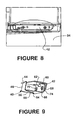
- Figure 8 is a front elevation view of the lower portion of the unit after installation and attachment.
- Figure 9 is a fragmentary perspective view showing detail of the attachment shown in Figure 8 from a different direction.
- Figure 10 is a perspective view of the upper left front corner of the unit after installation and attachment.
- Figure 11 is a perspective view of some of the cab interior with the unit partially inserted into the cabinet interior.
- Figure 12 is a perspective view of the cab interior after the unit has been fully inserted into the cabinet interior.
- Figure 13 is a perspective view of the cab interior showing the finished installation.
- Figure 1 shows a refrigerator unit 20 that comprises a casing 22 having a top wall, bottom wall, back wall, and two side walls that provide a frontal opening into the casing interior.
- a rectangular door 24 is hinged on casing 22 for swinging about a vertical axis along one vertical side of the frontal opening to open and close the opening.
- a door finish cover 26 is attached to the front of door 24 so that when unit 20 is installed in a cabinet 28 in a truck cab 29, as shown in Figure 13 , the finish cover cooperates with the cabinet to present the appearance of a quality product characterized by precise fit of the door finish cover to the cabinet.
- Cabinet 28 comprises a framework that supports the top and side walls.
- the back of the cabinet may be open and abutted against a side of cab 29.
- Three parts of that framework are utilized in the mounting of unit 20. They are upright frame members 30, 31 that are at respective vertical sides of the frontal opening of cabinet 28 and a horizontal bottom frame member 32 that bridges the bottom ends of members 30, 31.
- the cab floor 34 is utilized for supporting cabinet 28 and the refrigerator unit's weight when the unit is installed in the cabinet, as will be further explained.
- Bracket 38 is shown by itself in Figure 6 while brackets 40 and 42 are shown by themselves in Figures 2 and 4 respectively.
- Lower floor bracket 40 is fastened to cab floor 34 and to frame member 32 by a number of screws S.
- the construction of bracket 40 is best explained with reference to Figures 1 , 2 , 3 , and 9 .
- Bracket 40 is a one-piece metal stamping formed to provide a horizontal, rectangular-shaped, slide platform 44 that is supported vertically above cab floor 34 via vertical support legs 46, 48 at front and back ends. Legs 46, 48 are themselves supported on floor 34 via respective feet 50, 52 that are disposed horizontally beyond the ends of platform 44.
- the feet comprise holes, such as holes 54, 56 in foot 50, through which screws S are passed for threading into member 32 and floor 34 respectively and tightening to secure bracket 40 in place.
- Foot 52 is directly attached to floor 34.
- Foot 50 is attached directly to member 32, which in rests directly on floor 34.
- the sides of platform 44 and of leg 48 have stiffening flanges F.
- Foot 50 has a different shape from that of foot 52 because of a frontal extension of its area that rests on member 32.
- a vertical flange 58 At the front of the extended area is a vertical flange 58 that is noticeably wider (meaning in the direction of the cabinet's width) than the width of platform 44.
- two tabs 60, 62 are bent horizontally inward toward leg 46 at widthwise ends of the flange.
- flange 58 contains a respective through-hole 64, 66.
- a respective weldnut 68, 70 is affixed to the inside face of flange 58 at each through-hole 64, 66.
- Bracket 42 is a stamped metal part that comprises a horizontal mounting flange 72 and a vertical stop flange 74 that is bent downward along the front of flange 72. There are four through-holes 76 in flange 72 and two through-holes 78 in flange 74.
- Each side bracket is a stamped metal part that comprises upper and lower vertical mounting flanges 80, 82 that are parallel and horizontally offset from each other by a curved bend 84. There are two through-holes 86 in flange 80 and two through-holes 88 in flange 82.
- brackets 36, 38, and 42 Prior to installing unit 20 into cabinet 28, brackets 36, 38, and 42 are fastened to casing 22, as shown by Figures 1 , 5 , and 7 .
- brackets 36, 38 With each flange 80 of brackets 36, 38 disposed vertically above and laterally outboard of the respective casing side wall, flanges 82 of brackets 36, 38 are disposed flat against the casing side walls proximate the upper front corners of the latter and fastened to the casing, preferably by using rivets R..
- flange 72 With flange 74 of bracket 42 disposed toward the front and directed downward, flange 72 is disposed flat against the casing bottom wall proximate the front of the casing and fastened to the casing, preferably using rivets R.
- bracket 40 Prior to installing unit 20 into cabinet 28, bracket 40 is fastened to floor 34 and frame member 32, as shown by Figures 1 and 3 .
- Foot 50 is placed on a horizontal surface of member 32 with holes 54 and 56 in registration with holes 90, 92 on that surface of member 32.
- Foot 50 is fastened in place using headed screws S whose threaded shanks are passed through holes 54, 56 and tightened in holes 90, 92 to secure leg 46 to member 32.
- a through-hole in foot 52 registers with a hole in floor 34, and a screw S is passed through it and tightened in the hole in floor 34 to secure leg 48 to the floor.
- flange 58 is perpendicular to the side walls of the cabinet.
- Unit 20 is now ready to be installed. It is placed frontally of the open front of cabinet 28 and aligned with the cabinet opening. With the rear of casing 22 elevated, the unit is moved into the cabinet interior so that the rear of the casing bottom wall can rest on platform 44. This allows the casing to be slid rearward on the platform, preferably while the front is being lifted off floor 34 so that the edge of flange 74 doesn't scrape on the floor, while the platform increasingly bears the weight of the unit as the latter is slid farther rearward (see Figure 11 ).
- brackets 36, 38 During the fmal increment of sliding, widthwise centering of the casing is assured by the presence of brackets 36, 38. If the casing is not centered widthwise of the cabinet, one of the brackets will hit the corresponding upright member 30, 31 and therefore prevent the casing from being fully inserted.
- FIG. 12 shows that access for fastening brackets 36, 38 to the cabinet frame is provided because a drawer 96 that fits into space above unit 20 does not yet occupy that space. Once the mounting is complete, the drawer can be slid into that space.
- door cover 26 is attached to door 24 after the casing has been mounted in the cabinet to provide the finished appearance that can be seen in Figure 13 where the front face of the door cover is in substantial alignment with the front face of the drawer when both door and drawer are closed.
- the door cover can be attached to the door before the casing is inserted into the cabinet.
- Cabinet 28 is secured to the cab-in-white during the truck assembly process in a manner that provides compliance with relevant loading specifications, including those that might be encountered in the event of a crash. Accordingly, it may be inconvenient, unsuitable, or perhaps even impossible for unit 20 to be assembled into the cabinet before the cabinet is mounted in the cab.
- the mounting brackets that have been described here provide a convenient method for installing unit 20 into cabinet 28 with the cabinet already installed in the cab.
- the use of cab floor 34 to bear the weight of the unit in conjunction with the frame of the cabinet structure enable the unit to also comply with relevant loading specifications.
- the finished installation presents a quality appearance because of the true fit of the unit to the cabinet opening.
- cabinet 28 In the finished cab, cabinet 28 is behind the passenger seat 98 and in front of a bed 100 whose length is perpendicular to the fore-aft direction of the truck. Unit 20 can be installed and removed with seat 98 in place, but during truck build, it may be more convenient to install the unit before seat 98 is mounted on the floor.
Landscapes
- Engineering & Computer Science (AREA)
- Chemical & Material Sciences (AREA)
- Combustion & Propulsion (AREA)
- Physics & Mathematics (AREA)
- Mechanical Engineering (AREA)
- Thermal Sciences (AREA)
- General Engineering & Computer Science (AREA)
- Refrigerator Housings (AREA)
- Devices That Are Associated With Refrigeration Equipment (AREA)
Applications Claiming Priority (1)
| Application Number | Priority Date | Filing Date | Title |
|---|---|---|---|
| US11/949,113 US7703824B2 (en) | 2007-12-03 | 2007-12-03 | In-cab refrigerator mounting and method |
Publications (2)
| Publication Number | Publication Date |
|---|---|
| EP2067657A2 true EP2067657A2 (de) | 2009-06-10 |
| EP2067657A3 EP2067657A3 (de) | 2010-01-06 |
Family
ID=40328671
Family Applications (1)
| Application Number | Title | Priority Date | Filing Date |
|---|---|---|---|
| EP08020027A Withdrawn EP2067657A3 (de) | 2007-12-03 | 2008-11-17 | Befestigung eines Kühlschranks im Fahrzeug |
Country Status (3)
| Country | Link |
|---|---|
| US (1) | US7703824B2 (de) |
| EP (1) | EP2067657A3 (de) |
| CA (1) | CA2643816A1 (de) |
Families Citing this family (48)
| Publication number | Priority date | Publication date | Assignee | Title |
|---|---|---|---|---|
| US20100133966A1 (en) * | 2008-11-28 | 2010-06-03 | Dragos Murgurel Blaga | Appliance |
| DE102009013809A1 (de) * | 2009-03-18 | 2010-09-23 | Liebherr-Hausgeräte Ochsenhausen GmbH | Kühl- und/oder Gefriergeräte |
| DE102011011738B4 (de) * | 2011-02-18 | 2016-05-12 | Naber Holding Gmbh & Co. Kg | Möbelsystem |
| US9221210B2 (en) | 2012-04-11 | 2015-12-29 | Whirlpool Corporation | Method to create vacuum insulated cabinets for refrigerators |
| US8986483B2 (en) | 2012-04-02 | 2015-03-24 | Whirlpool Corporation | Method of making a folded vacuum insulated structure |
| US9371029B2 (en) | 2013-03-15 | 2016-06-21 | Winnebago Industries, Inc. | Slidable table for a vehicle |
| US9689604B2 (en) | 2014-02-24 | 2017-06-27 | Whirlpool Corporation | Multi-section core vacuum insulation panels with hybrid barrier film envelope |
| US10052819B2 (en) | 2014-02-24 | 2018-08-21 | Whirlpool Corporation | Vacuum packaged 3D vacuum insulated door structure and method therefor using a tooling fixture |
| US9476633B2 (en) | 2015-03-02 | 2016-10-25 | Whirlpool Corporation | 3D vacuum panel and a folding approach to create the 3D vacuum panel from a 2D vacuum panel of non-uniform thickness |
| US10161669B2 (en) | 2015-03-05 | 2018-12-25 | Whirlpool Corporation | Attachment arrangement for vacuum insulated door |
| US9897370B2 (en) | 2015-03-11 | 2018-02-20 | Whirlpool Corporation | Self-contained pantry box system for insertion into an appliance |
| US9441779B1 (en) | 2015-07-01 | 2016-09-13 | Whirlpool Corporation | Split hybrid insulation structure for an appliance |
| US10222116B2 (en) | 2015-12-08 | 2019-03-05 | Whirlpool Corporation | Method and apparatus for forming a vacuum insulated structure for an appliance having a pressing mechanism incorporated within an insulation delivery system |
| US11052579B2 (en) | 2015-12-08 | 2021-07-06 | Whirlpool Corporation | Method for preparing a densified insulation material for use in appliance insulated structure |
| US12508751B2 (en) | 2015-12-08 | 2025-12-30 | Whirlpool Corporation | Insulation compaction device and method for forming an insulated structure for an appliance |
| US10422573B2 (en) | 2015-12-08 | 2019-09-24 | Whirlpool Corporation | Insulation structure for an appliance having a uniformly mixed multi-component insulation material, and a method for even distribution of material combinations therein |
| US10429125B2 (en) | 2015-12-08 | 2019-10-01 | Whirlpool Corporation | Insulation structure for an appliance having a uniformly mixed multi-component insulation material, and a method for even distribution of material combinations therein |
| US10041724B2 (en) | 2015-12-08 | 2018-08-07 | Whirlpool Corporation | Methods for dispensing and compacting insulation materials into a vacuum sealed structure |
| US11994336B2 (en) | 2015-12-09 | 2024-05-28 | Whirlpool Corporation | Vacuum insulated structure with thermal bridge breaker with heat loop |
| EP3387351B1 (de) | 2015-12-09 | 2021-10-13 | Whirlpool Corporation | Vakuumisolationskonstruktionen mit mehreren isolatoren |
| US10422569B2 (en) | 2015-12-21 | 2019-09-24 | Whirlpool Corporation | Vacuum insulated door construction |
| US10610985B2 (en) | 2015-12-28 | 2020-04-07 | Whirlpool Corporation | Multilayer barrier materials with PVD or plasma coating for vacuum insulated structure |
| US10018406B2 (en) | 2015-12-28 | 2018-07-10 | Whirlpool Corporation | Multi-layer gas barrier materials for vacuum insulated structure |
| US10807298B2 (en) | 2015-12-29 | 2020-10-20 | Whirlpool Corporation | Molded gas barrier parts for vacuum insulated structure |
| US10030905B2 (en) | 2015-12-29 | 2018-07-24 | Whirlpool Corporation | Method of fabricating a vacuum insulated appliance structure |
| US11247369B2 (en) | 2015-12-30 | 2022-02-15 | Whirlpool Corporation | Method of fabricating 3D vacuum insulated refrigerator structure having core material |
| EP3443284B1 (de) | 2016-04-15 | 2020-11-18 | Whirlpool Corporation | Vakuumisolierte kühlstruktur mit dreidimensionalen eigenschaften |
| EP3443285B1 (de) | 2016-04-15 | 2021-03-10 | Whirlpool Corporation | Vakuumisolierter kühlschrank |
| EP3491308B1 (de) | 2016-07-26 | 2021-03-10 | Whirlpool Corporation | Verkleidungsbrecher einer vakuumisolierten struktur |
| EP3500804B1 (de) | 2016-08-18 | 2022-06-22 | Whirlpool Corporation | Kühlschrank |
| US10550586B2 (en) * | 2016-09-12 | 2020-02-04 | Austin Hardware And Supply, Inc. | Cabinet with snap-in frame |
| EP3548813B1 (de) | 2016-12-02 | 2023-05-31 | Whirlpool Corporation | Scharnierhalteanordnung |
| US10352613B2 (en) | 2016-12-05 | 2019-07-16 | Whirlpool Corporation | Pigmented monolayer liner for appliances and methods of making the same |
| KR102658453B1 (ko) | 2017-02-02 | 2024-04-17 | 엘지전자 주식회사 | 차량용 냉장고, 및 차량 |
| CN107804206A (zh) * | 2017-11-02 | 2018-03-16 | 广东英得尔实业发展有限公司 | 一种房车专用车载冰箱 |
| CN107843058A (zh) * | 2017-11-02 | 2018-03-27 | 广东英得尔实业发展有限公司 | 一种车载冰箱滑动门、车载冰箱及车载冰箱的使用方法 |
| US10625679B1 (en) * | 2018-03-12 | 2020-04-21 | Adam J. Wurzer | Kit for assembling a cabinet in a sleeper cab of a truck |
| CN110345684A (zh) * | 2018-04-08 | 2019-10-18 | 陈明 | 一种新型冰箱 |
| US10907888B2 (en) | 2018-06-25 | 2021-02-02 | Whirlpool Corporation | Hybrid pigmented hot stitched color liner system |
| US10907891B2 (en) | 2019-02-18 | 2021-02-02 | Whirlpool Corporation | Trim breaker for a structural cabinet that incorporates a structural glass contact surface |
| US10933923B1 (en) * | 2019-03-27 | 2021-03-02 | Adam J. Wurzer | Horizontal cabinet kit in sleeper cab of a truck |
| CN110077303B (zh) * | 2019-04-22 | 2024-09-13 | 绍兴上虞北方电子制造有限公司 | 一种放置使用稳定的车载冰箱 |
| US11731549B2 (en) | 2020-02-18 | 2023-08-22 | Toyota Motor Engineering & Manufacturing North America, Inc. | Vehicle cooler with passenger cabin access |
| US12070924B2 (en) | 2020-07-27 | 2024-08-27 | Whirlpool Corporation | Appliance liner having natural fibers |
| US11993196B2 (en) * | 2021-10-14 | 2024-05-28 | Adrian Steel Company | Shelf system |
| CN117091343A (zh) * | 2022-05-12 | 2023-11-21 | 青岛海尔电冰箱有限公司 | 定位件及具有该定位件的冰箱 |
| CN117091341A (zh) * | 2022-05-12 | 2023-11-21 | 青岛海尔电冰箱有限公司 | 定位件及具有该定位件的冰箱 |
| CN117091342A (zh) * | 2022-05-12 | 2023-11-21 | 青岛海尔电冰箱有限公司 | 定位件及可应用该定位件的冰箱 |
Citations (1)
| Publication number | Priority date | Publication date | Assignee | Title |
|---|---|---|---|---|
| DE10024893A1 (de) | 1999-09-14 | 2001-03-15 | Electrolux Siegen Gmbh | Kältegerät, das vorzugsweise nach dem Absorberprinzip arbeitet, sowie Fahrzeug mit einem derartigen Kältegerät |
Family Cites Families (11)
| Publication number | Priority date | Publication date | Assignee | Title |
|---|---|---|---|---|
| US3856248A (en) * | 1973-06-25 | 1974-12-24 | D Labelle | Appliance leveling device |
| US4331312A (en) * | 1979-12-26 | 1982-05-25 | Lavoe Paul A | Instrument mounting rack |
| SE8205136L (sv) * | 1982-09-09 | 1984-03-10 | Electrolux Ab | Anordning vid husvagn med kylskap |
| US5899546A (en) * | 1997-06-04 | 1999-05-04 | Maytag Corporation | Refrigerator cabinet and method of assembling the same |
| US5967634A (en) * | 1997-07-14 | 1999-10-19 | Whirlpool Corporation | Support base for a built-in oven |
| US6005195A (en) * | 1998-01-12 | 1999-12-21 | Lucent Technologies Inc. | Cable retainer clip for electrical and/or optical equipment mounting structures |
| DE102004012495A1 (de) * | 2004-03-15 | 2005-10-06 | BSH Bosch und Siemens Hausgeräte GmbH | Einbau-Kältegerät mit Sockelaggregat |
| DE202004013513U1 (de) * | 2004-08-30 | 2005-06-02 | Dometic Gmbh | Tragestruktur für ein Küchensystem und Küchensystem |
| US7533917B2 (en) * | 2005-04-07 | 2009-05-19 | International Truck Intellectual Property Company, Llc | Integrated kitchen unit for a mobile vehicle |
| EP1881281A1 (de) * | 2006-07-17 | 2008-01-23 | Whirlpool Corporation | Einbaukühlschrank mit erhöhtem Innenvolumen |
| NZ551533A (en) * | 2006-11-22 | 2008-08-29 | Fisher & Paykel Appliances Ltd | Preventing tipping of appliance when drawer pulled out |
-
2007
- 2007-12-03 US US11/949,113 patent/US7703824B2/en not_active Expired - Fee Related
-
2008
- 2008-11-13 CA CA002643816A patent/CA2643816A1/en not_active Abandoned
- 2008-11-17 EP EP08020027A patent/EP2067657A3/de not_active Withdrawn
Patent Citations (1)
| Publication number | Priority date | Publication date | Assignee | Title |
|---|---|---|---|---|
| DE10024893A1 (de) | 1999-09-14 | 2001-03-15 | Electrolux Siegen Gmbh | Kältegerät, das vorzugsweise nach dem Absorberprinzip arbeitet, sowie Fahrzeug mit einem derartigen Kältegerät |
Also Published As
| Publication number | Publication date |
|---|---|
| CA2643816A1 (en) | 2009-06-03 |
| EP2067657A3 (de) | 2010-01-06 |
| US20090140537A1 (en) | 2009-06-04 |
| US7703824B2 (en) | 2010-04-27 |
Similar Documents
| Publication | Publication Date | Title |
|---|---|---|
| US7703824B2 (en) | In-cab refrigerator mounting and method | |
| US6328365B1 (en) | Integrated bed drawer assembly for vehicles | |
| US9713978B2 (en) | Vertically adjustable and removable headache rack system | |
| US5022626A (en) | Vehicle accessory stand | |
| US4494465A (en) | Table for use with automobile trunks and the like | |
| US9346404B1 (en) | Decorative side bar for a motor vehicle | |
| US5829655A (en) | Assembly-in-place storage container for use behind the front seats of an extended cab truck | |
| US6024398A (en) | Sliding seat assembly for an automobile | |
| US7578546B2 (en) | Removable chassis skirt | |
| US8020911B2 (en) | Sliding cargo carrier for vehicle | |
| US7823948B2 (en) | System for shelf mounting in mobile truck body | |
| US6270138B1 (en) | Removable shelving arrangement for vehicles | |
| US6145910A (en) | Method of installing a vehicle interior | |
| US20140069971A1 (en) | Roof Rack Mounting System | |
| US6986540B2 (en) | Bed system for a pickup truck | |
| US2867484A (en) | Automobile tray or writing desk | |
| CA2799687C (en) | Wall and roof liner for installation in a cargo vehicle | |
| US20060265806A1 (en) | Mounting system for RV furniture | |
| US20250381915A1 (en) | Adjustable step assemblies for a truck tractor | |
| JP3268424B2 (ja) | 車両のフロントアンダランプロテクタの取付構造 | |
| US7651154B1 (en) | One piece modular design for rear seat head restraints and snap in bracket design | |
| JPH1134727A (ja) | 自動車の延長フロア | |
| AU2005200748B2 (en) | Vehicle equipment rack | |
| US20100237657A1 (en) | Truck floor assembly | |
| WO2025226268A1 (en) | Vehicle bed side cargo panel device |
Legal Events
| Date | Code | Title | Description |
|---|---|---|---|
| PUAI | Public reference made under article 153(3) epc to a published international application that has entered the european phase |
Free format text: ORIGINAL CODE: 0009012 |
|
| AK | Designated contracting states |
Kind code of ref document: A2 Designated state(s): AT BE BG CH CY CZ DE DK EE ES FI FR GB GR HR HU IE IS IT LI LT LU LV MC MT NL NO PL PT RO SE SI SK TR |
|
| AX | Request for extension of the european patent |
Extension state: AL BA MK RS |
|
| PUAL | Search report despatched |
Free format text: ORIGINAL CODE: 0009013 |
|
| AK | Designated contracting states |
Kind code of ref document: A3 Designated state(s): AT BE BG CH CY CZ DE DK EE ES FI FR GB GR HR HU IE IS IT LI LT LU LV MC MT NL NO PL PT RO SE SI SK TR |
|
| AX | Request for extension of the european patent |
Extension state: AL BA MK RS |
|
| AKY | No designation fees paid | ||
| STAA | Information on the status of an ep patent application or granted ep patent |
Free format text: STATUS: THE APPLICATION IS DEEMED TO BE WITHDRAWN |
|
| 18D | Application deemed to be withdrawn |
Effective date: 20100706 |
|
| REG | Reference to a national code |
Ref country code: DE Ref legal event code: 8566 |