EP2067175B1 - Electronic device module comprising polyolefin copolymer - Google Patents
Electronic device module comprising polyolefin copolymer Download PDFInfo
- Publication number
- EP2067175B1 EP2067175B1 EP07814922A EP07814922A EP2067175B1 EP 2067175 B1 EP2067175 B1 EP 2067175B1 EP 07814922 A EP07814922 A EP 07814922A EP 07814922 A EP07814922 A EP 07814922A EP 2067175 B1 EP2067175 B1 EP 2067175B1
- Authority
- EP
- European Patent Office
- Prior art keywords
- module
- electronic device
- copolymer
- less
- polymeric material
- Prior art date
- Legal status (The legal status is an assumption and is not a legal conclusion. Google has not performed a legal analysis and makes no representation as to the accuracy of the status listed.)
- Active
Links
- 229920000098 polyolefin Polymers 0.000 title claims description 57
- 239000000463 material Substances 0.000 claims description 75
- 229920000642 polymer Polymers 0.000 claims description 55
- 239000011521 glass Substances 0.000 claims description 46
- 239000003999 initiator Substances 0.000 claims description 39
- 229920001577 copolymer Polymers 0.000 claims description 30
- 239000004711 α-olefin Substances 0.000 claims description 24
- 150000003254 radicals Chemical class 0.000 claims description 23
- 150000002894 organic compounds Chemical class 0.000 claims description 13
- 239000000155 melt Substances 0.000 claims description 12
- 239000003112 inhibitor Substances 0.000 claims description 11
- FPYJFEHAWHCUMM-UHFFFAOYSA-N maleic anhydride Chemical compound O=C1OC(=O)C=C1 FPYJFEHAWHCUMM-UHFFFAOYSA-N 0.000 claims description 11
- 125000002915 carbonyl group Chemical group [*:2]C([*:1])=O 0.000 claims description 6
- NKSJNEHGWDZZQF-UHFFFAOYSA-N ethenyl(trimethoxy)silane Chemical compound CO[Si](OC)(OC)C=C NKSJNEHGWDZZQF-UHFFFAOYSA-N 0.000 claims description 6
- UKRDPEFKFJNXQM-UHFFFAOYSA-N vinylsilane Chemical compound [SiH3]C=C UKRDPEFKFJNXQM-UHFFFAOYSA-N 0.000 claims description 6
- FWDBOZPQNFPOLF-UHFFFAOYSA-N ethenyl(triethoxy)silane Chemical compound CCO[Si](OCC)(OCC)C=C FWDBOZPQNFPOLF-UHFFFAOYSA-N 0.000 claims description 4
- CTQNGGLPUBDAKN-UHFFFAOYSA-N O-Xylene Chemical compound CC1=CC=CC=C1C CTQNGGLPUBDAKN-UHFFFAOYSA-N 0.000 claims description 3
- 239000003795 chemical substances by application Substances 0.000 claims description 3
- 239000012632 extractable Substances 0.000 claims description 3
- 239000002356 single layer Substances 0.000 claims description 3
- 239000008096 xylene Substances 0.000 claims description 3
- 125000002081 peroxide group Chemical group 0.000 claims 1
- 239000010408 film Substances 0.000 description 65
- 238000000034 method Methods 0.000 description 41
- 239000000203 mixture Substances 0.000 description 41
- 239000010410 layer Substances 0.000 description 33
- 238000004132 cross linking Methods 0.000 description 31
- 150000002978 peroxides Chemical class 0.000 description 30
- -1 azo compound Chemical class 0.000 description 24
- 239000005038 ethylene vinyl acetate Substances 0.000 description 23
- 229920001200 poly(ethylene-vinyl acetate) Polymers 0.000 description 23
- 238000012360 testing method Methods 0.000 description 20
- BLRPTPMANUNPDV-UHFFFAOYSA-N Silane Chemical compound [SiH4] BLRPTPMANUNPDV-UHFFFAOYSA-N 0.000 description 18
- 229910000077 silane Inorganic materials 0.000 description 18
- 239000000654 additive Substances 0.000 description 16
- 229920005989 resin Polymers 0.000 description 14
- 239000011347 resin Substances 0.000 description 14
- VGGSQFUCUMXWEO-UHFFFAOYSA-N Ethene Chemical compound C=C VGGSQFUCUMXWEO-UHFFFAOYSA-N 0.000 description 13
- 239000005977 Ethylene Substances 0.000 description 13
- 239000011241 protective layer Substances 0.000 description 13
- 239000012963 UV stabilizer Substances 0.000 description 11
- 238000001125 extrusion Methods 0.000 description 11
- 238000012545 processing Methods 0.000 description 11
- 230000005855 radiation Effects 0.000 description 11
- 239000000126 substance Substances 0.000 description 11
- 239000008393 encapsulating agent Substances 0.000 description 10
- XLYOFNOQVPJJNP-UHFFFAOYSA-N water Substances O XLYOFNOQVPJJNP-UHFFFAOYSA-N 0.000 description 10
- QTBSBXVTEAMEQO-UHFFFAOYSA-N Acetic acid Chemical compound CC(O)=O QTBSBXVTEAMEQO-UHFFFAOYSA-N 0.000 description 9
- 238000009472 formulation Methods 0.000 description 9
- 229920000573 polyethylene Polymers 0.000 description 9
- LFQSCWFLJHTTHZ-UHFFFAOYSA-N Ethanol Chemical compound CCO LFQSCWFLJHTTHZ-UHFFFAOYSA-N 0.000 description 8
- 239000004698 Polyethylene Substances 0.000 description 8
- HEAMQYHBJQWOSS-UHFFFAOYSA-N ethene;oct-1-ene Chemical compound C=C.CCCCCCC=C HEAMQYHBJQWOSS-UHFFFAOYSA-N 0.000 description 8
- 229910052751 metal Inorganic materials 0.000 description 8
- 239000002184 metal Substances 0.000 description 8
- 150000004756 silanes Chemical class 0.000 description 8
- 239000000758 substrate Substances 0.000 description 8
- VXNZUUAINFGPBY-UHFFFAOYSA-N 1-Butene Chemical compound CCC=C VXNZUUAINFGPBY-UHFFFAOYSA-N 0.000 description 7
- BJELTSYBAHKXRW-UHFFFAOYSA-N 2,4,6-triallyloxy-1,3,5-triazine Chemical compound C=CCOC1=NC(OCC=C)=NC(OCC=C)=N1 BJELTSYBAHKXRW-UHFFFAOYSA-N 0.000 description 7
- UZFMOKQJFYMBGY-UHFFFAOYSA-N 4-hydroxy-TEMPO Chemical group CC1(C)CC(O)CC(C)(C)N1[O] UZFMOKQJFYMBGY-UHFFFAOYSA-N 0.000 description 7
- 239000004971 Cross linker Substances 0.000 description 7
- 150000001875 compounds Chemical class 0.000 description 7
- 229920000578 graft copolymer Polymers 0.000 description 7
- 238000004519 manufacturing process Methods 0.000 description 7
- 238000002844 melting Methods 0.000 description 7
- 230000008018 melting Effects 0.000 description 7
- QUAMTGJKVDWJEQ-UHFFFAOYSA-N octabenzone Chemical compound OC1=CC(OCCCCCCCC)=CC=C1C(=O)C1=CC=CC=C1 QUAMTGJKVDWJEQ-UHFFFAOYSA-N 0.000 description 7
- 239000010409 thin film Substances 0.000 description 7
- LIKMAJRDDDTEIG-UHFFFAOYSA-N 1-hexene Chemical compound CCCCC=C LIKMAJRDDDTEIG-UHFFFAOYSA-N 0.000 description 6
- SWZOQAGVRGQLDV-UHFFFAOYSA-N 4-[2-(4-hydroxy-2,2,6,6-tetramethylpiperidin-1-yl)ethoxy]-4-oxobutanoic acid Chemical compound CC1(C)CC(O)CC(C)(C)N1CCOC(=O)CCC(O)=O SWZOQAGVRGQLDV-UHFFFAOYSA-N 0.000 description 6
- 239000003963 antioxidant agent Substances 0.000 description 6
- ORECYURYFJYPKY-UHFFFAOYSA-N n,n'-bis(2,2,6,6-tetramethylpiperidin-4-yl)hexane-1,6-diamine;2,4,6-trichloro-1,3,5-triazine;2,4,4-trimethylpentan-2-amine Chemical compound CC(C)(C)CC(C)(C)N.ClC1=NC(Cl)=NC(Cl)=N1.C1C(C)(C)NC(C)(C)CC1NCCCCCCNC1CC(C)(C)NC(C)(C)C1 ORECYURYFJYPKY-UHFFFAOYSA-N 0.000 description 6
- 230000001681 protective effect Effects 0.000 description 6
- 238000002834 transmittance Methods 0.000 description 6
- KWKAKUADMBZCLK-UHFFFAOYSA-N 1-octene Chemical compound CCCCCCC=C KWKAKUADMBZCLK-UHFFFAOYSA-N 0.000 description 5
- 150000001412 amines Chemical class 0.000 description 5
- 230000015572 biosynthetic process Effects 0.000 description 5
- IAQRGUVFOMOMEM-UHFFFAOYSA-N butene Natural products CC=CC IAQRGUVFOMOMEM-UHFFFAOYSA-N 0.000 description 5
- 239000003054 catalyst Substances 0.000 description 5
- 238000003475 lamination Methods 0.000 description 5
- 230000003287 optical effect Effects 0.000 description 5
- 230000002028 premature Effects 0.000 description 5
- JLZIIHMTTRXXIN-UHFFFAOYSA-N 2-(2-hydroxy-4-methoxybenzoyl)benzoic acid Chemical compound OC1=CC(OC)=CC=C1C(=O)C1=CC=CC=C1C(O)=O JLZIIHMTTRXXIN-UHFFFAOYSA-N 0.000 description 4
- QQONPFPTGQHPMA-UHFFFAOYSA-N Propene Chemical compound CC=C QQONPFPTGQHPMA-UHFFFAOYSA-N 0.000 description 4
- UIIMBOGNXHQVGW-UHFFFAOYSA-M Sodium bicarbonate Chemical compound [Na+].OC([O-])=O UIIMBOGNXHQVGW-UHFFFAOYSA-M 0.000 description 4
- PPBRXRYQALVLMV-UHFFFAOYSA-N Styrene Chemical compound C=CC1=CC=CC=C1 PPBRXRYQALVLMV-UHFFFAOYSA-N 0.000 description 4
- 238000002835 absorbance Methods 0.000 description 4
- 230000000996 additive effect Effects 0.000 description 4
- RWCCWEUUXYIKHB-UHFFFAOYSA-N benzophenone Chemical compound C=1C=CC=CC=1C(=O)C1=CC=CC=C1 RWCCWEUUXYIKHB-UHFFFAOYSA-N 0.000 description 4
- 239000012965 benzophenone Substances 0.000 description 4
- 230000005540 biological transmission Effects 0.000 description 4
- 238000001723 curing Methods 0.000 description 4
- 230000005670 electromagnetic radiation Effects 0.000 description 4
- 150000003839 salts Chemical class 0.000 description 4
- 238000002211 ultraviolet spectrum Methods 0.000 description 4
- DMWVYCCGCQPJEA-UHFFFAOYSA-N 2,5-bis(tert-butylperoxy)-2,5-dimethylhexane Chemical compound CC(C)(C)OOC(C)(C)CCC(C)(C)OOC(C)(C)C DMWVYCCGCQPJEA-UHFFFAOYSA-N 0.000 description 3
- CERQOIWHTDAKMF-UHFFFAOYSA-N Methacrylic acid Chemical compound CC(=C)C(O)=O CERQOIWHTDAKMF-UHFFFAOYSA-N 0.000 description 3
- 239000006096 absorbing agent Substances 0.000 description 3
- 230000001070 adhesive effect Effects 0.000 description 3
- 150000001336 alkenes Chemical class 0.000 description 3
- 238000004458 analytical method Methods 0.000 description 3
- 230000003078 antioxidant effect Effects 0.000 description 3
- 238000006243 chemical reaction Methods 0.000 description 3
- 238000010276 construction Methods 0.000 description 3
- 238000007796 conventional method Methods 0.000 description 3
- 239000012792 core layer Substances 0.000 description 3
- 239000003431 cross linking reagent Substances 0.000 description 3
- 238000009826 distribution Methods 0.000 description 3
- 230000000694 effects Effects 0.000 description 3
- 238000005516 engineering process Methods 0.000 description 3
- HQQADJVZYDDRJT-UHFFFAOYSA-N ethene;prop-1-ene Chemical group C=C.CC=C HQQADJVZYDDRJT-UHFFFAOYSA-N 0.000 description 3
- 239000000945 filler Substances 0.000 description 3
- NZYMWGXNIUZYRC-UHFFFAOYSA-N hexadecyl 3,5-ditert-butyl-4-hydroxybenzoate Chemical compound CCCCCCCCCCCCCCCCOC(=O)C1=CC(C(C)(C)C)=C(O)C(C(C)(C)C)=C1 NZYMWGXNIUZYRC-UHFFFAOYSA-N 0.000 description 3
- 230000007062 hydrolysis Effects 0.000 description 3
- 238000006460 hydrolysis reaction Methods 0.000 description 3
- 239000000178 monomer Substances 0.000 description 3
- 238000000465 moulding Methods 0.000 description 3
- TVMXDCGIABBOFY-UHFFFAOYSA-N n-Octanol Natural products CCCCCCCC TVMXDCGIABBOFY-UHFFFAOYSA-N 0.000 description 3
- 238000002360 preparation method Methods 0.000 description 3
- 238000007789 sealing Methods 0.000 description 3
- 230000035882 stress Effects 0.000 description 3
- 238000000870 ultraviolet spectroscopy Methods 0.000 description 3
- 125000000391 vinyl group Chemical group [H]C([*])=C([H])[H] 0.000 description 3
- MYRTYDVEIRVNKP-UHFFFAOYSA-N 1,2-Divinylbenzene Chemical compound C=CC1=CC=CC=C1C=C MYRTYDVEIRVNKP-UHFFFAOYSA-N 0.000 description 2
- YXIWHUQXZSMYRE-UHFFFAOYSA-N 1,3-benzothiazole-2-thiol Chemical compound C1=CC=C2SC(S)=NC2=C1 YXIWHUQXZSMYRE-UHFFFAOYSA-N 0.000 description 2
- AFFLGGQVNFXPEV-UHFFFAOYSA-N 1-decene Chemical compound CCCCCCCCC=C AFFLGGQVNFXPEV-UHFFFAOYSA-N 0.000 description 2
- CRSBERNSMYQZNG-UHFFFAOYSA-N 1-dodecene Chemical compound CCCCCCCCCCC=C CRSBERNSMYQZNG-UHFFFAOYSA-N 0.000 description 2
- GQEZCXVZFLOKMC-UHFFFAOYSA-N 1-hexadecene Chemical compound CCCCCCCCCCCCCCC=C GQEZCXVZFLOKMC-UHFFFAOYSA-N 0.000 description 2
- HFDVRLIODXPAHB-UHFFFAOYSA-N 1-tetradecene Chemical compound CCCCCCCCCCCCC=C HFDVRLIODXPAHB-UHFFFAOYSA-N 0.000 description 2
- SMZOUWXMTYCWNB-UHFFFAOYSA-N 2-(2-methoxy-5-methylphenyl)ethanamine Chemical compound COC1=CC=C(C)C=C1CCN SMZOUWXMTYCWNB-UHFFFAOYSA-N 0.000 description 2
- 125000003903 2-propenyl group Chemical group [H]C([*])([H])C([H])=C([H])[H] 0.000 description 2
- SJECZPVISLOESU-UHFFFAOYSA-N 3-trimethoxysilylpropan-1-amine Chemical compound CO[Si](OC)(OC)CCCN SJECZPVISLOESU-UHFFFAOYSA-N 0.000 description 2
- WSSSPWUEQFSQQG-UHFFFAOYSA-N 4-methyl-1-pentene Chemical compound CC(C)CC=C WSSSPWUEQFSQQG-UHFFFAOYSA-N 0.000 description 2
- NIXOWILDQLNWCW-UHFFFAOYSA-M Acrylate Chemical compound [O-]C(=O)C=C NIXOWILDQLNWCW-UHFFFAOYSA-M 0.000 description 2
- 229920000089 Cyclic olefin copolymer Polymers 0.000 description 2
- RGSFGYAAUTVSQA-UHFFFAOYSA-N Cyclopentane Chemical compound C1CCCC1 RGSFGYAAUTVSQA-UHFFFAOYSA-N 0.000 description 2
- 239000005062 Polybutadiene Substances 0.000 description 2
- KVOZXXSUSRZIKD-UHFFFAOYSA-N Prop-2-enylcyclohexane Chemical compound C=CCC1CCCCC1 KVOZXXSUSRZIKD-UHFFFAOYSA-N 0.000 description 2
- NINIDFKCEFEMDL-UHFFFAOYSA-N Sulfur Chemical compound [S] NINIDFKCEFEMDL-UHFFFAOYSA-N 0.000 description 2
- XTXRWKRVRITETP-UHFFFAOYSA-N Vinyl acetate Chemical group CC(=O)OC=C XTXRWKRVRITETP-UHFFFAOYSA-N 0.000 description 2
- 238000010521 absorption reaction Methods 0.000 description 2
- 159000000021 acetate salts Chemical class 0.000 description 2
- 230000002378 acidificating effect Effects 0.000 description 2
- 150000001252 acrylic acid derivatives Chemical class 0.000 description 2
- 239000000853 adhesive Substances 0.000 description 2
- 150000008064 anhydrides Chemical class 0.000 description 2
- ISAOCJYIOMOJEB-UHFFFAOYSA-N benzoin Chemical compound C=1C=CC=CC=1C(O)C(=O)C1=CC=CC=C1 ISAOCJYIOMOJEB-UHFFFAOYSA-N 0.000 description 2
- 238000005266 casting Methods 0.000 description 2
- 230000015556 catabolic process Effects 0.000 description 2
- 239000003153 chemical reaction reagent Substances 0.000 description 2
- 238000013329 compounding Methods 0.000 description 2
- 238000000748 compression moulding Methods 0.000 description 2
- 239000011243 crosslinked material Substances 0.000 description 2
- 125000004122 cyclic group Chemical group 0.000 description 2
- 238000006731 degradation reaction Methods 0.000 description 2
- 238000013461 design Methods 0.000 description 2
- 238000010586 diagram Methods 0.000 description 2
- 238000000113 differential scanning calorimetry Methods 0.000 description 2
- 150000002148 esters Chemical class 0.000 description 2
- QHZOMAXECYYXGP-UHFFFAOYSA-N ethene;prop-2-enoic acid Chemical compound C=C.OC(=O)C=C QHZOMAXECYYXGP-UHFFFAOYSA-N 0.000 description 2
- 229920001038 ethylene copolymer Polymers 0.000 description 2
- 235000012438 extruded product Nutrition 0.000 description 2
- 239000007863 gel particle Substances 0.000 description 2
- 238000011065 in-situ storage Methods 0.000 description 2
- 229920000554 ionomer Polymers 0.000 description 2
- 238000011068 loading method Methods 0.000 description 2
- 230000007774 longterm Effects 0.000 description 2
- 150000002734 metacrylic acid derivatives Chemical class 0.000 description 2
- 238000002156 mixing Methods 0.000 description 2
- CCCMONHAUSKTEQ-UHFFFAOYSA-N octadec-1-ene Chemical compound CCCCCCCCCCCCCCCCC=C CCCMONHAUSKTEQ-UHFFFAOYSA-N 0.000 description 2
- 150000001451 organic peroxides Chemical class 0.000 description 2
- 239000008188 pellet Substances 0.000 description 2
- 150000002989 phenols Chemical class 0.000 description 2
- 150000003018 phosphorus compounds Chemical class 0.000 description 2
- 239000000049 pigment Substances 0.000 description 2
- 229920003023 plastic Polymers 0.000 description 2
- 239000004033 plastic Substances 0.000 description 2
- 229920002857 polybutadiene Polymers 0.000 description 2
- 229920006124 polyolefin elastomer Polymers 0.000 description 2
- 229920001296 polysiloxane Polymers 0.000 description 2
- 125000004805 propylene group Chemical group [H]C([H])([H])C([H])([*:1])C([H])([H])[*:2] 0.000 description 2
- 229920005604 random copolymer Polymers 0.000 description 2
- 229910000030 sodium bicarbonate Inorganic materials 0.000 description 2
- 235000017557 sodium bicarbonate Nutrition 0.000 description 2
- 239000003381 stabilizer Substances 0.000 description 2
- 238000003756 stirring Methods 0.000 description 2
- 229920001897 terpolymer Polymers 0.000 description 2
- 238000010998 test method Methods 0.000 description 2
- 229920002554 vinyl polymer Polymers 0.000 description 2
- WBYWAXJHAXSJNI-VOTSOKGWSA-M .beta-Phenylacrylic acid Natural products [O-]C(=O)\C=C\C1=CC=CC=C1 WBYWAXJHAXSJNI-VOTSOKGWSA-M 0.000 description 1
- NALFRYPTRXKZPN-UHFFFAOYSA-N 1,1-bis(tert-butylperoxy)-3,3,5-trimethylcyclohexane Chemical compound CC1CC(C)(C)CC(OOC(C)(C)C)(OOC(C)(C)C)C1 NALFRYPTRXKZPN-UHFFFAOYSA-N 0.000 description 1
- WKKRYWQLVOISAU-UHFFFAOYSA-N 1,3,5-tris(2-tert-butylperoxypropan-2-yl)benzene Chemical compound CC(C)(C)OOC(C)(C)C1=CC(C(C)(C)OOC(C)(C)C)=CC(C(C)(C)OOC(C)(C)C)=C1 WKKRYWQLVOISAU-UHFFFAOYSA-N 0.000 description 1
- 150000005208 1,4-dihydroxybenzenes Chemical class 0.000 description 1
- JHGGYGMFCRSWIZ-UHFFFAOYSA-N 2,2-dichloro-1-(4-phenoxyphenyl)ethanone Chemical compound C1=CC(C(=O)C(Cl)Cl)=CC=C1OC1=CC=CC=C1 JHGGYGMFCRSWIZ-UHFFFAOYSA-N 0.000 description 1
- KWVGIHKZDCUPEU-UHFFFAOYSA-N 2,2-dimethoxy-2-phenylacetophenone Chemical compound C=1C=CC=CC=1C(OC)(OC)C(=O)C1=CC=CC=C1 KWVGIHKZDCUPEU-UHFFFAOYSA-N 0.000 description 1
- ODBCKCWTWALFKM-UHFFFAOYSA-N 2,5-bis(tert-butylperoxy)-2,5-dimethylhex-3-yne Chemical compound CC(C)(C)OOC(C)(C)C#CC(C)(C)OOC(C)(C)C ODBCKCWTWALFKM-UHFFFAOYSA-N 0.000 description 1
- TUAPLLGBMYGPST-UHFFFAOYSA-N 2,5-dimethyl-2,5-bis(2-methylbutan-2-ylperoxy)hexane Chemical compound CCC(C)(C)OOC(C)(C)CCC(C)(C)OOC(C)(C)CC TUAPLLGBMYGPST-UHFFFAOYSA-N 0.000 description 1
- PZILQNGWHUGDLZ-UHFFFAOYSA-N 2-(2-acetyloxypropan-2-yldiazenyl)propan-2-yl acetate Chemical compound CC(=O)OC(C)(C)N=NC(C)(C)OC(C)=O PZILQNGWHUGDLZ-UHFFFAOYSA-N 0.000 description 1
- XMNIXWIUMCBBBL-UHFFFAOYSA-N 2-(2-phenylpropan-2-ylperoxy)propan-2-ylbenzene Chemical compound C=1C=CC=CC=1C(C)(C)OOC(C)(C)C1=CC=CC=C1 XMNIXWIUMCBBBL-UHFFFAOYSA-N 0.000 description 1
- JAHNSTQSQJOJLO-UHFFFAOYSA-N 2-(3-fluorophenyl)-1h-imidazole Chemical compound FC1=CC=CC(C=2NC=CN=2)=C1 JAHNSTQSQJOJLO-UHFFFAOYSA-N 0.000 description 1
- JJRDRFZYKKFYMO-UHFFFAOYSA-N 2-methyl-2-(2-methylbutan-2-ylperoxy)butane Chemical compound CCC(C)(C)OOC(C)(C)CC JJRDRFZYKKFYMO-UHFFFAOYSA-N 0.000 description 1
- PHIGUQOUWMSXFV-UHFFFAOYSA-N 2-methyl-2-[2-(2-methylbutan-2-ylperoxy)propan-2-ylperoxy]butane Chemical compound CCC(C)(C)OOC(C)(C)OOC(C)(C)CC PHIGUQOUWMSXFV-UHFFFAOYSA-N 0.000 description 1
- BIISIZOQPWZPPS-UHFFFAOYSA-N 2-tert-butylperoxypropan-2-ylbenzene Chemical compound CC(C)(C)OOC(C)(C)C1=CC=CC=C1 BIISIZOQPWZPPS-UHFFFAOYSA-N 0.000 description 1
- WBWXVCMXGYSMQA-UHFFFAOYSA-N 3,9-bis[2,4-bis(2-phenylpropan-2-yl)phenoxy]-2,4,8,10-tetraoxa-3,9-diphosphaspiro[5.5]undecane Chemical compound C=1C=C(OP2OCC3(CO2)COP(OC=2C(=CC(=CC=2)C(C)(C)C=2C=CC=CC=2)C(C)(C)C=2C=CC=CC=2)OC3)C(C(C)(C)C=2C=CC=CC=2)=CC=1C(C)(C)C1=CC=CC=C1 WBWXVCMXGYSMQA-UHFFFAOYSA-N 0.000 description 1
- CPGFMWPQXUXQRX-UHFFFAOYSA-N 3-amino-3-(4-fluorophenyl)propanoic acid Chemical compound OC(=O)CC(N)C1=CC=C(F)C=C1 CPGFMWPQXUXQRX-UHFFFAOYSA-N 0.000 description 1
- BUZICZZQJDLXJN-UHFFFAOYSA-N 3-azaniumyl-4-hydroxybutanoate Chemical compound OCC(N)CC(O)=O BUZICZZQJDLXJN-UHFFFAOYSA-N 0.000 description 1
- XDLMVUHYZWKMMD-UHFFFAOYSA-N 3-trimethoxysilylpropyl 2-methylprop-2-enoate Chemical compound CO[Si](OC)(OC)CCCOC(=O)C(C)=C XDLMVUHYZWKMMD-UHFFFAOYSA-N 0.000 description 1
- OCVLSHAVSIYKLI-UHFFFAOYSA-N 3h-1,3-thiazole-2-thione Chemical class SC1=NC=CS1 OCVLSHAVSIYKLI-UHFFFAOYSA-N 0.000 description 1
- NPAYGRADBRCXPA-UHFFFAOYSA-N 4,4-bis(2-methylbutan-2-ylperoxy)pentanoic acid Chemical compound CCC(C)(C)OOC(C)(CCC(O)=O)OOC(C)(C)CC NPAYGRADBRCXPA-UHFFFAOYSA-N 0.000 description 1
- QISOBCMNUJQOJU-UHFFFAOYSA-N 4-bromo-1h-pyrazole-5-carboxylic acid Chemical compound OC(=O)C=1NN=CC=1Br QISOBCMNUJQOJU-UHFFFAOYSA-N 0.000 description 1
- CCOJJJCQUHWYAT-UHFFFAOYSA-N 4-methyl-4-(2-methylbutan-2-ylperoxy)pentan-2-ol Chemical compound CCC(C)(C)OOC(C)(C)CC(C)O CCOJJJCQUHWYAT-UHFFFAOYSA-N 0.000 description 1
- JNSWFNBIZLIBPH-UHFFFAOYSA-N 4-tert-butylperoxy-4-methylpentan-2-ol Chemical compound CC(O)CC(C)(C)OOC(C)(C)C JNSWFNBIZLIBPH-UHFFFAOYSA-N 0.000 description 1
- MARUHZGHZWCEQU-UHFFFAOYSA-N 5-phenyl-2h-tetrazole Chemical compound C1=CC=CC=C1C1=NNN=N1 MARUHZGHZWCEQU-UHFFFAOYSA-N 0.000 description 1
- HUKPVYBUJRAUAG-UHFFFAOYSA-N 7-benzo[a]phenalenone Chemical compound C1=CC(C(=O)C=2C3=CC=CC=2)=C2C3=CC=CC2=C1 HUKPVYBUJRAUAG-UHFFFAOYSA-N 0.000 description 1
- RZVAJINKPMORJF-UHFFFAOYSA-N Acetaminophen Chemical compound CC(=O)NC1=CC=C(O)C=C1 RZVAJINKPMORJF-UHFFFAOYSA-N 0.000 description 1
- UIERETOOQGIECD-UHFFFAOYSA-N Angelic acid Natural products CC=C(C)C(O)=O UIERETOOQGIECD-UHFFFAOYSA-N 0.000 description 1
- 239000004342 Benzoyl peroxide Substances 0.000 description 1
- OMPJBNCRMGITSC-UHFFFAOYSA-N Benzoylperoxide Chemical compound C=1C=CC=CC=1C(=O)OOC(=O)C1=CC=CC=C1 OMPJBNCRMGITSC-UHFFFAOYSA-N 0.000 description 1
- LSNNMFCWUKXFEE-UHFFFAOYSA-M Bisulfite Chemical compound OS([O-])=O LSNNMFCWUKXFEE-UHFFFAOYSA-M 0.000 description 1
- 101100389815 Caenorhabditis elegans eva-1 gene Proteins 0.000 description 1
- WBYWAXJHAXSJNI-SREVYHEPSA-N Cinnamic acid Chemical compound OC(=O)\C=C/C1=CC=CC=C1 WBYWAXJHAXSJNI-SREVYHEPSA-N 0.000 description 1
- RYGMFSIKBFXOCR-UHFFFAOYSA-N Copper Chemical compound [Cu] RYGMFSIKBFXOCR-UHFFFAOYSA-N 0.000 description 1
- XDTMQSROBMDMFD-UHFFFAOYSA-N Cyclohexane Chemical compound C1CCCCC1 XDTMQSROBMDMFD-UHFFFAOYSA-N 0.000 description 1
- 229920002943 EPDM rubber Polymers 0.000 description 1
- 241001441571 Hiodontidae Species 0.000 description 1
- OWYWGLHRNBIFJP-UHFFFAOYSA-N Ipazine Chemical compound CCN(CC)C1=NC(Cl)=NC(NC(C)C)=N1 OWYWGLHRNBIFJP-UHFFFAOYSA-N 0.000 description 1
- 239000002841 Lewis acid Substances 0.000 description 1
- CERQOIWHTDAKMF-UHFFFAOYSA-M Methacrylate Chemical compound CC(=C)C([O-])=O CERQOIWHTDAKMF-UHFFFAOYSA-M 0.000 description 1
- UBUCNCOMADRQHX-UHFFFAOYSA-N N-Nitrosodiphenylamine Chemical compound C=1C=CC=CC=1N(N=O)C1=CC=CC=C1 UBUCNCOMADRQHX-UHFFFAOYSA-N 0.000 description 1
- 238000005481 NMR spectroscopy Methods 0.000 description 1
- 239000004743 Polypropylene Substances 0.000 description 1
- 239000006087 Silane Coupling Agent Substances 0.000 description 1
- 244000028419 Styrax benzoin Species 0.000 description 1
- 235000000126 Styrax benzoin Nutrition 0.000 description 1
- 235000008411 Sumatra benzointree Nutrition 0.000 description 1
- 239000004809 Teflon Substances 0.000 description 1
- OKKRPWIIYQTPQF-UHFFFAOYSA-N Trimethylolpropane trimethacrylate Chemical compound CC(=C)C(=O)OCC(CC)(COC(=O)C(C)=C)COC(=O)C(C)=C OKKRPWIIYQTPQF-UHFFFAOYSA-N 0.000 description 1
- 229920010346 Very Low Density Polyethylene (VLDPE) Polymers 0.000 description 1
- BEIOEBMXPVYLRY-UHFFFAOYSA-N [4-[4-bis(2,4-ditert-butylphenoxy)phosphanylphenyl]phenyl]-bis(2,4-ditert-butylphenoxy)phosphane Chemical compound CC(C)(C)C1=CC(C(C)(C)C)=CC=C1OP(C=1C=CC(=CC=1)C=1C=CC(=CC=1)P(OC=1C(=CC(=CC=1)C(C)(C)C)C(C)(C)C)OC=1C(=CC(=CC=1)C(C)(C)C)C(C)(C)C)OC1=CC=C(C(C)(C)C)C=C1C(C)(C)C BEIOEBMXPVYLRY-UHFFFAOYSA-N 0.000 description 1
- KTSFMFGEAAANTF-UHFFFAOYSA-N [Cu].[Se].[Se].[In] Chemical compound [Cu].[Se].[Se].[In] KTSFMFGEAAANTF-UHFFFAOYSA-N 0.000 description 1
- UKLDJPRMSDWDSL-UHFFFAOYSA-L [dibutyl(dodecanoyloxy)stannyl] dodecanoate Chemical compound CCCCCCCCCCCC(=O)O[Sn](CCCC)(CCCC)OC(=O)CCCCCCCCCCC UKLDJPRMSDWDSL-UHFFFAOYSA-L 0.000 description 1
- RMKZLFMHXZAGTM-UHFFFAOYSA-N [dimethoxy(propyl)silyl]oxymethyl prop-2-enoate Chemical compound CCC[Si](OC)(OC)OCOC(=O)C=C RMKZLFMHXZAGTM-UHFFFAOYSA-N 0.000 description 1
- XQBCVRSTVUHIGH-UHFFFAOYSA-L [dodecanoyloxy(dioctyl)stannyl] dodecanoate Chemical compound CCCCCCCCCCCC(=O)O[Sn](CCCCCCCC)(CCCCCCCC)OC(=O)CCCCCCCCCCC XQBCVRSTVUHIGH-UHFFFAOYSA-L 0.000 description 1
- 239000002250 absorbent Substances 0.000 description 1
- 230000002745 absorbent Effects 0.000 description 1
- 230000002411 adverse Effects 0.000 description 1
- 230000032683 aging Effects 0.000 description 1
- 238000013019 agitation Methods 0.000 description 1
- 150000005215 alkyl ethers Chemical class 0.000 description 1
- 125000000217 alkyl group Chemical group 0.000 description 1
- 150000004808 allyl alcohols Chemical class 0.000 description 1
- XYLMUPLGERFSHI-UHFFFAOYSA-N alpha-Methylstyrene Chemical compound CC(=C)C1=CC=CC=C1 XYLMUPLGERFSHI-UHFFFAOYSA-N 0.000 description 1
- 229910052782 aluminium Inorganic materials 0.000 description 1
- XAGFODPZIPBFFR-UHFFFAOYSA-N aluminium Chemical compound [Al] XAGFODPZIPBFFR-UHFFFAOYSA-N 0.000 description 1
- 229910021417 amorphous silicon Inorganic materials 0.000 description 1
- 150000004982 aromatic amines Chemical class 0.000 description 1
- 125000001769 aryl amino group Chemical group 0.000 description 1
- 230000004888 barrier function Effects 0.000 description 1
- UHOVQNZJYSORNB-UHFFFAOYSA-N benzene Substances C1=CC=CC=C1 UHOVQNZJYSORNB-UHFFFAOYSA-N 0.000 description 1
- 229960002130 benzoin Drugs 0.000 description 1
- 235000019400 benzoyl peroxide Nutrition 0.000 description 1
- 230000005250 beta ray Effects 0.000 description 1
- DQXBYHZEEUGOBF-UHFFFAOYSA-N but-3-enoic acid;ethene Chemical compound C=C.OC(=O)CC=C DQXBYHZEEUGOBF-UHFFFAOYSA-N 0.000 description 1
- FLTDLGPEJAJANE-UHFFFAOYSA-N but-3-enyl triethyl silicate Chemical group CCO[Si](OCC)(OCC)OCCC=C FLTDLGPEJAJANE-UHFFFAOYSA-N 0.000 description 1
- 125000004369 butenyl group Chemical group C(=CCC)* 0.000 description 1
- BXIQXYOPGBXIEM-UHFFFAOYSA-N butyl 4,4-bis(tert-butylperoxy)pentanoate Chemical compound CCCCOC(=O)CCC(C)(OOC(C)(C)C)OOC(C)(C)C BXIQXYOPGBXIEM-UHFFFAOYSA-N 0.000 description 1
- CJZGTCYPCWQAJB-UHFFFAOYSA-L calcium stearate Chemical compound [Ca+2].CCCCCCCCCCCCCCCCCC([O-])=O.CCCCCCCCCCCCCCCCCC([O-])=O CJZGTCYPCWQAJB-UHFFFAOYSA-L 0.000 description 1
- 239000008116 calcium stearate Substances 0.000 description 1
- 235000013539 calcium stearate Nutrition 0.000 description 1
- 238000003490 calendering Methods 0.000 description 1
- DKVNPHBNOWQYFE-UHFFFAOYSA-N carbamodithioic acid Chemical class NC(S)=S DKVNPHBNOWQYFE-UHFFFAOYSA-N 0.000 description 1
- 150000001728 carbonyl compounds Chemical class 0.000 description 1
- 150000001735 carboxylic acids Chemical class 0.000 description 1
- 229920002301 cellulose acetate Polymers 0.000 description 1
- 238000010382 chemical cross-linking Methods 0.000 description 1
- 229930016911 cinnamic acid Natural products 0.000 description 1
- 235000013985 cinnamic acid Nutrition 0.000 description 1
- 238000004140 cleaning Methods 0.000 description 1
- 239000011248 coating agent Substances 0.000 description 1
- 238000000576 coating method Methods 0.000 description 1
- 238000009833 condensation Methods 0.000 description 1
- 230000005494 condensation Effects 0.000 description 1
- 239000004020 conductor Substances 0.000 description 1
- 238000001816 cooling Methods 0.000 description 1
- 229910052802 copper Inorganic materials 0.000 description 1
- 239000010949 copper Substances 0.000 description 1
- ZOUQIAGHKFLHIA-UHFFFAOYSA-L copper;n,n-dimethylcarbamodithioate Chemical compound [Cu+2].CN(C)C([S-])=S.CN(C)C([S-])=S ZOUQIAGHKFLHIA-UHFFFAOYSA-L 0.000 description 1
- 230000007797 corrosion Effects 0.000 description 1
- 238000005260 corrosion Methods 0.000 description 1
- 229920006037 cross link polymer Polymers 0.000 description 1
- LDHQCZJRKDOVOX-NSCUHMNNSA-N crotonic acid Chemical compound C\C=C\C(O)=O LDHQCZJRKDOVOX-NSCUHMNNSA-N 0.000 description 1
- 125000000596 cyclohexenyl group Chemical group C1(=CCCCC1)* 0.000 description 1
- 238000000354 decomposition reaction Methods 0.000 description 1
- 230000000593 degrading effect Effects 0.000 description 1
- 230000032798 delamination Effects 0.000 description 1
- LSXWFXONGKSEMY-UHFFFAOYSA-N di-tert-butyl peroxide Chemical compound CC(C)(C)OOC(C)(C)C LSXWFXONGKSEMY-UHFFFAOYSA-N 0.000 description 1
- AFZSMODLJJCVPP-UHFFFAOYSA-N dibenzothiazol-2-yl disulfide Chemical compound C1=CC=C2SC(SSC=3SC4=CC=CC=C4N=3)=NC2=C1 AFZSMODLJJCVPP-UHFFFAOYSA-N 0.000 description 1
- PGAXJQVAHDTGBB-UHFFFAOYSA-N dibutylcarbamothioylsulfanyl n,n-dibutylcarbamodithioate Chemical compound CCCCN(CCCC)C(=S)SSC(=S)N(CCCC)CCCC PGAXJQVAHDTGBB-UHFFFAOYSA-N 0.000 description 1
- 239000012975 dibutyltin dilaurate Substances 0.000 description 1
- 150000001993 dienes Chemical class 0.000 description 1
- 238000007865 diluting Methods 0.000 description 1
- GKHRLTCUMXVTAV-UHFFFAOYSA-N dimoracin Chemical compound C1=C(O)C=C2OC(C3=CC(O)=C(C(=C3)O)C3C4C(C5=C(O)C=C(C=C5O3)C=3OC5=CC(O)=CC=C5C=3)C=C(CC4(C)C)C)=CC2=C1 GKHRLTCUMXVTAV-UHFFFAOYSA-N 0.000 description 1
- 238000002845 discoloration Methods 0.000 description 1
- 229940069096 dodecene Drugs 0.000 description 1
- 238000001035 drying Methods 0.000 description 1
- 229920001971 elastomer Polymers 0.000 description 1
- 230000005611 electricity Effects 0.000 description 1
- 238000010894 electron beam technology Methods 0.000 description 1
- 238000010828 elution Methods 0.000 description 1
- 238000005538 encapsulation Methods 0.000 description 1
- 239000003822 epoxy resin Substances 0.000 description 1
- BXOUVIIITJXIKB-UHFFFAOYSA-N ethene;styrene Chemical compound C=C.C=CC1=CC=CC=C1 BXOUVIIITJXIKB-UHFFFAOYSA-N 0.000 description 1
- LDLDYFCCDKENPD-UHFFFAOYSA-N ethenylcyclohexane Chemical compound C=CC1CCCCC1 LDLDYFCCDKENPD-UHFFFAOYSA-N 0.000 description 1
- OWXRYJGXNWIKBK-UHFFFAOYSA-N ethoxy [(1-oxo-1-phenylpropan-2-ylidene)amino] carbonate Chemical compound CCOOC(=O)ON=C(C)C(=O)C1=CC=CC=C1 OWXRYJGXNWIKBK-UHFFFAOYSA-N 0.000 description 1
- MKGMCCVHOVSDTI-UHFFFAOYSA-N ethyl 2-(3,6,6,9,9-pentamethyl-1,2,4,5-tetraoxonan-3-yl)acetate Chemical compound CCOC(=O)CC1(C)OOC(C)(C)CCC(C)(C)OO1 MKGMCCVHOVSDTI-UHFFFAOYSA-N 0.000 description 1
- NICWAKGKDIAMOD-UHFFFAOYSA-N ethyl 3,3-bis(2-methylbutan-2-ylperoxy)butanoate Chemical compound CCOC(=O)CC(C)(OOC(C)(C)CC)OOC(C)(C)CC NICWAKGKDIAMOD-UHFFFAOYSA-N 0.000 description 1
- HARQWLDROVMFJE-UHFFFAOYSA-N ethyl 3,3-bis(tert-butylperoxy)butanoate Chemical compound CCOC(=O)CC(C)(OOC(C)(C)C)OOC(C)(C)C HARQWLDROVMFJE-UHFFFAOYSA-N 0.000 description 1
- 230000001747 exhibiting effect Effects 0.000 description 1
- 239000012467 final product Substances 0.000 description 1
- 239000006260 foam Substances 0.000 description 1
- 238000005194 fractionation Methods 0.000 description 1
- 230000005251 gamma ray Effects 0.000 description 1
- 230000009477 glass transition Effects 0.000 description 1
- 235000019382 gum benzoic Nutrition 0.000 description 1
- LNEPOXFFQSENCJ-UHFFFAOYSA-N haloperidol Chemical compound C1CC(O)(C=2C=CC(Cl)=CC=2)CCN1CCCC(=O)C1=CC=C(F)C=C1 LNEPOXFFQSENCJ-UHFFFAOYSA-N 0.000 description 1
- DMEGYFMYUHOHGS-UHFFFAOYSA-N heptamethylene Natural products C1CCCCCC1 DMEGYFMYUHOHGS-UHFFFAOYSA-N 0.000 description 1
- 125000001183 hydrocarbyl group Chemical group 0.000 description 1
- 229910052739 hydrogen Inorganic materials 0.000 description 1
- 239000001257 hydrogen Substances 0.000 description 1
- 150000002432 hydroperoxides Chemical class 0.000 description 1
- 238000010348 incorporation Methods 0.000 description 1
- 230000000977 initiatory effect Effects 0.000 description 1
- 230000005865 ionizing radiation Effects 0.000 description 1
- OWFXIOWLTKNBAP-UHFFFAOYSA-N isoamyl nitrite Chemical compound CC(C)CCON=O OWFXIOWLTKNBAP-UHFFFAOYSA-N 0.000 description 1
- 125000000555 isopropenyl group Chemical group [H]\C([H])=C(\*)C([H])([H])[H] 0.000 description 1
- 125000001449 isopropyl group Chemical group [H]C([H])([H])C([H])(*)C([H])([H])[H] 0.000 description 1
- 150000007517 lewis acids Chemical class 0.000 description 1
- 239000004973 liquid crystal related substance Substances 0.000 description 1
- VZCYOOQTPOCHFL-UPHRSURJSA-N maleic acid Chemical compound OC(=O)\C=C/C(O)=O VZCYOOQTPOCHFL-UPHRSURJSA-N 0.000 description 1
- 239000011159 matrix material Substances 0.000 description 1
- 238000010128 melt processing Methods 0.000 description 1
- 239000012968 metallocene catalyst Substances 0.000 description 1
- WBYWAXJHAXSJNI-UHFFFAOYSA-N methyl p-hydroxycinnamate Natural products OC(=O)C=CC1=CC=CC=C1 WBYWAXJHAXSJNI-UHFFFAOYSA-N 0.000 description 1
- GDOPTJXRTPNYNR-UHFFFAOYSA-N methyl-cyclopentane Natural products CC1CCCC1 GDOPTJXRTPNYNR-UHFFFAOYSA-N 0.000 description 1
- LVHBHZANLOWSRM-UHFFFAOYSA-N methylenebutanedioic acid Natural products OC(=O)CC(=C)C(O)=O LVHBHZANLOWSRM-UHFFFAOYSA-N 0.000 description 1
- 238000003801 milling Methods 0.000 description 1
- 238000013008 moisture curing Methods 0.000 description 1
- 229910021421 monocrystalline silicon Inorganic materials 0.000 description 1
- FOAIGCPESMNWQP-WCWDXBQESA-N n-[1-[[1-[[1-[[1-[[1-[[1-[[1-[[3-[1-(dimethylamino)propan-2-ylamino]-3-oxopropyl]amino]-2-methyl-1-oxopropan-2-yl]amino]-2-methyl-1-oxopropan-2-yl]amino]-4-methyl-1-oxopentan-2-yl]amino]-4-methyl-1-oxopentan-2-yl]amino]-2-methyl-1-oxopropan-2-yl]amino]-3- Chemical compound CCC(C)\C=C\C(=O)N1CC(C)CC1C(=O)NC(CC(C)CC(O)CC(=O)CC)C(=O)NC(C(O)C(C)C)C(=O)NC(C)(C)C(=O)NC(CC(C)C)C(=O)NC(CC(C)C)C(=O)NC(C)(C)C(=O)NC(C)(C)C(=O)NCCC(=O)NC(C)CN(C)C FOAIGCPESMNWQP-WCWDXBQESA-N 0.000 description 1
- 150000002826 nitrites Chemical class 0.000 description 1
- 229910052757 nitrogen Inorganic materials 0.000 description 1
- ODUCDPQEXGNKDN-UHFFFAOYSA-N nitroxyl Chemical compound O=N ODUCDPQEXGNKDN-UHFFFAOYSA-N 0.000 description 1
- JFNLZVQOOSMTJK-KNVOCYPGSA-N norbornene Chemical compound C1[C@@H]2CC[C@H]1C=C2 JFNLZVQOOSMTJK-KNVOCYPGSA-N 0.000 description 1
- SSDSCDGVMJFTEQ-UHFFFAOYSA-N octadecyl 3-(3,5-ditert-butyl-4-hydroxyphenyl)propanoate Chemical compound CCCCCCCCCCCCCCCCCCOC(=O)CCC1=CC(C(C)(C)C)=C(O)C(C(C)(C)C)=C1 SSDSCDGVMJFTEQ-UHFFFAOYSA-N 0.000 description 1
- 239000012934 organic peroxide initiator Substances 0.000 description 1
- 230000003647 oxidation Effects 0.000 description 1
- 238000007254 oxidation reaction Methods 0.000 description 1
- 230000001590 oxidative effect Effects 0.000 description 1
- 239000003348 petrochemical agent Substances 0.000 description 1
- 239000011990 phillips catalyst Substances 0.000 description 1
- AQSJGOWTSHOLKH-UHFFFAOYSA-N phosphite(3-) Chemical class [O-]P([O-])[O-] AQSJGOWTSHOLKH-UHFFFAOYSA-N 0.000 description 1
- XRBCRPZXSCBRTK-UHFFFAOYSA-N phosphonous acid Chemical class OPO XRBCRPZXSCBRTK-UHFFFAOYSA-N 0.000 description 1
- 229920002037 poly(vinyl butyral) polymer Polymers 0.000 description 1
- 229920000647 polyepoxide Polymers 0.000 description 1
- 229920005862 polyol Polymers 0.000 description 1
- 229920005672 polyolefin resin Polymers 0.000 description 1
- 150000003077 polyols Chemical class 0.000 description 1
- 235000013824 polyphenols Nutrition 0.000 description 1
- 229920001155 polypropylene Polymers 0.000 description 1
- 238000010791 quenching Methods 0.000 description 1
- 230000000171 quenching effect Effects 0.000 description 1
- 239000000376 reactant Substances 0.000 description 1
- 230000000630 rising effect Effects 0.000 description 1
- 239000005060 rubber Substances 0.000 description 1
- 239000000565 sealant Substances 0.000 description 1
- 239000004065 semiconductor Substances 0.000 description 1
- 230000035939 shock Effects 0.000 description 1
- 229920002050 silicone resin Polymers 0.000 description 1
- 238000002791 soaking Methods 0.000 description 1
- 239000002904 solvent Substances 0.000 description 1
- 229910052717 sulfur Inorganic materials 0.000 description 1
- 239000011593 sulfur Substances 0.000 description 1
- 238000009864 tensile test Methods 0.000 description 1
- 229920006029 tetra-polymer Polymers 0.000 description 1
- 238000005979 thermal decomposition reaction Methods 0.000 description 1
- 239000012815 thermoplastic material Substances 0.000 description 1
- KUAZQDVKQLNFPE-UHFFFAOYSA-N thiram Chemical compound CN(C)C(=S)SSC(=S)N(C)C KUAZQDVKQLNFPE-UHFFFAOYSA-N 0.000 description 1
- 229960002447 thiram Drugs 0.000 description 1
- UIERETOOQGIECD-ONEGZZNKSA-N tiglic acid Chemical compound C\C=C(/C)C(O)=O UIERETOOQGIECD-ONEGZZNKSA-N 0.000 description 1
- LDHQCZJRKDOVOX-UHFFFAOYSA-N trans-crotonic acid Natural products CC=CC(O)=O LDHQCZJRKDOVOX-UHFFFAOYSA-N 0.000 description 1
- YUYCVXFAYWRXLS-UHFFFAOYSA-N trimethoxysilane Chemical compound CO[SiH](OC)OC YUYCVXFAYWRXLS-UHFFFAOYSA-N 0.000 description 1
- WGKLOLBTFWFKOD-UHFFFAOYSA-N tris(2-nonylphenyl) phosphite Chemical compound CCCCCCCCCC1=CC=CC=C1OP(OC=1C(=CC=CC=1)CCCCCCCCC)OC1=CC=CC=C1CCCCCCCCC WGKLOLBTFWFKOD-UHFFFAOYSA-N 0.000 description 1
- MGMXGCZJYUCMGY-UHFFFAOYSA-N tris(4-nonylphenyl) phosphite Chemical compound C1=CC(CCCCCCCCC)=CC=C1OP(OC=1C=CC(CCCCCCCCC)=CC=1)OC1=CC=C(CCCCCCCCC)C=C1 MGMXGCZJYUCMGY-UHFFFAOYSA-N 0.000 description 1
- 238000009281 ultraviolet germicidal irradiation Methods 0.000 description 1
- 238000002371 ultraviolet--visible spectrum Methods 0.000 description 1
- 108010071304 univin Proteins 0.000 description 1
Images


Classifications
-
- H—ELECTRICITY
- H01—ELECTRIC ELEMENTS
- H01L—SEMICONDUCTOR DEVICES NOT COVERED BY CLASS H10
- H01L31/00—Semiconductor devices sensitive to infrared radiation, light, electromagnetic radiation of shorter wavelength or corpuscular radiation and specially adapted either for the conversion of the energy of such radiation into electrical energy or for the control of electrical energy by such radiation; Processes or apparatus specially adapted for the manufacture or treatment thereof or of parts thereof; Details thereof
- H01L31/04—Semiconductor devices sensitive to infrared radiation, light, electromagnetic radiation of shorter wavelength or corpuscular radiation and specially adapted either for the conversion of the energy of such radiation into electrical energy or for the control of electrical energy by such radiation; Processes or apparatus specially adapted for the manufacture or treatment thereof or of parts thereof; Details thereof adapted as photovoltaic [PV] conversion devices
- H01L31/042—PV modules or arrays of single PV cells
- H01L31/048—Encapsulation of modules
- H01L31/0481—Encapsulation of modules characterised by the composition of the encapsulation material
-
- B—PERFORMING OPERATIONS; TRANSPORTING
- B32—LAYERED PRODUCTS
- B32B—LAYERED PRODUCTS, i.e. PRODUCTS BUILT-UP OF STRATA OF FLAT OR NON-FLAT, e.g. CELLULAR OR HONEYCOMB, FORM
- B32B17/00—Layered products essentially comprising sheet glass, or glass, slag, or like fibres
- B32B17/06—Layered products essentially comprising sheet glass, or glass, slag, or like fibres comprising glass as the main or only constituent of a layer, next to another layer of a specific material
- B32B17/10—Layered products essentially comprising sheet glass, or glass, slag, or like fibres comprising glass as the main or only constituent of a layer, next to another layer of a specific material of synthetic resin
- B32B17/10005—Layered products essentially comprising sheet glass, or glass, slag, or like fibres comprising glass as the main or only constituent of a layer, next to another layer of a specific material of synthetic resin laminated safety glass or glazing
- B32B17/10009—Layered products essentially comprising sheet glass, or glass, slag, or like fibres comprising glass as the main or only constituent of a layer, next to another layer of a specific material of synthetic resin laminated safety glass or glazing characterized by the number, the constitution or treatment of glass sheets
- B32B17/10018—Layered products essentially comprising sheet glass, or glass, slag, or like fibres comprising glass as the main or only constituent of a layer, next to another layer of a specific material of synthetic resin laminated safety glass or glazing characterized by the number, the constitution or treatment of glass sheets comprising only one glass sheet
-
- B—PERFORMING OPERATIONS; TRANSPORTING
- B32—LAYERED PRODUCTS
- B32B—LAYERED PRODUCTS, i.e. PRODUCTS BUILT-UP OF STRATA OF FLAT OR NON-FLAT, e.g. CELLULAR OR HONEYCOMB, FORM
- B32B17/00—Layered products essentially comprising sheet glass, or glass, slag, or like fibres
- B32B17/06—Layered products essentially comprising sheet glass, or glass, slag, or like fibres comprising glass as the main or only constituent of a layer, next to another layer of a specific material
- B32B17/10—Layered products essentially comprising sheet glass, or glass, slag, or like fibres comprising glass as the main or only constituent of a layer, next to another layer of a specific material of synthetic resin
- B32B17/10005—Layered products essentially comprising sheet glass, or glass, slag, or like fibres comprising glass as the main or only constituent of a layer, next to another layer of a specific material of synthetic resin laminated safety glass or glazing
- B32B17/1055—Layered products essentially comprising sheet glass, or glass, slag, or like fibres comprising glass as the main or only constituent of a layer, next to another layer of a specific material of synthetic resin laminated safety glass or glazing characterized by the resin layer, i.e. interlayer
- B32B17/10678—Layered products essentially comprising sheet glass, or glass, slag, or like fibres comprising glass as the main or only constituent of a layer, next to another layer of a specific material of synthetic resin laminated safety glass or glazing characterized by the resin layer, i.e. interlayer comprising UV absorbers or stabilizers, e.g. antioxidants
-
- C—CHEMISTRY; METALLURGY
- C08—ORGANIC MACROMOLECULAR COMPOUNDS; THEIR PREPARATION OR CHEMICAL WORKING-UP; COMPOSITIONS BASED THEREON
- C08L—COMPOSITIONS OF MACROMOLECULAR COMPOUNDS
- C08L51/00—Compositions of graft polymers in which the grafted component is obtained by reactions only involving carbon-to-carbon unsaturated bonds; Compositions of derivatives of such polymers
- C08L51/06—Compositions of graft polymers in which the grafted component is obtained by reactions only involving carbon-to-carbon unsaturated bonds; Compositions of derivatives of such polymers grafted on to homopolymers or copolymers of aliphatic hydrocarbons containing only one carbon-to-carbon double bond
-
- H—ELECTRICITY
- H01—ELECTRIC ELEMENTS
- H01L—SEMICONDUCTOR DEVICES NOT COVERED BY CLASS H10
- H01L31/00—Semiconductor devices sensitive to infrared radiation, light, electromagnetic radiation of shorter wavelength or corpuscular radiation and specially adapted either for the conversion of the energy of such radiation into electrical energy or for the control of electrical energy by such radiation; Processes or apparatus specially adapted for the manufacture or treatment thereof or of parts thereof; Details thereof
- H01L31/18—Processes or apparatus specially adapted for the manufacture or treatment of these devices or of parts thereof
-
- B—PERFORMING OPERATIONS; TRANSPORTING
- B32—LAYERED PRODUCTS
- B32B—LAYERED PRODUCTS, i.e. PRODUCTS BUILT-UP OF STRATA OF FLAT OR NON-FLAT, e.g. CELLULAR OR HONEYCOMB, FORM
- B32B2457/00—Electrical equipment
- B32B2457/12—Photovoltaic modules
-
- Y—GENERAL TAGGING OF NEW TECHNOLOGICAL DEVELOPMENTS; GENERAL TAGGING OF CROSS-SECTIONAL TECHNOLOGIES SPANNING OVER SEVERAL SECTIONS OF THE IPC; TECHNICAL SUBJECTS COVERED BY FORMER USPC CROSS-REFERENCE ART COLLECTIONS [XRACs] AND DIGESTS
- Y02—TECHNOLOGIES OR APPLICATIONS FOR MITIGATION OR ADAPTATION AGAINST CLIMATE CHANGE
- Y02E—REDUCTION OF GREENHOUSE GAS [GHG] EMISSIONS, RELATED TO ENERGY GENERATION, TRANSMISSION OR DISTRIBUTION
- Y02E10/00—Energy generation through renewable energy sources
- Y02E10/50—Photovoltaic [PV] energy
Definitions
- the invention relates to electronic device modules.
- the invention relates to electronic device modules comprising an electronic device, e.g., a solar or photovoltaic (PV) cell, and a protective polymeric material while in another aspect, the invention relates to electronic device modules in which the protective polymeric material is a polyolefin polymer with at least one of (a) a density of less than 0.90 grams per cubic centimeter (g/cm 3 ), (b) a low modulus, (c) a melt point less than 95°C, (d) an ⁇ -olefin content between 15-50 weight percent (wt%) based on the weight of the copolymer, (c) a glass transition temperature (Tg) of less than -35°C, and (f) a short chain branch distribution index (SCBDI or CDBI) of 50 or greater.
- the invention relates to a method of making an electronic device module.
- Polymeric materials are commonly used in the manufacture of modules comprising one or more electronic devices including, but not limited to, solar cells (also known as photovoltaic cells), liquid crystal panels, electro-luminescent devices and plasma display units.
- the modules often comprise an electronic device in combination with one or more substrates, e.g., one or more glass cover sheets, often positioned between two substrates in which one or both of the substrates comprise glass, metal, plastic, rubber or another material.
- the polymeric materials are typically used as the encapsulant or sealant for the module or depending upon the design of the module, as a skin layer component of the module, e.g., a backskin in a solar cell module.
- Typical polymeric materials for these purposes include silicone resins, epoxy resins, polyvinyl butyral resins, cellulose acetate, ethylene-vinyl acetate copolymer (EVA) and ionomers.
- United States Patent Application Publication 2001/0045229 A1 identifies a number of properties desirable in any polymeric material that is intended for use in the construction of an electronic device module. These properties include (i) protecting the device from exposure to the outside environment, e.g., moisture and air, particularly over long periods of time (ii) protecting against mechanical shock, (iii) strong adhesion to the electronic device and substrates, (iv) easy processing, including sealing, (v) good transparency, particularly in applications in which light or other electromagnetic radiation is important, e.g., solar cell modules, (vi) short cure times with protection of the electronic device from mechanical stress resulting from polymer shrinkage during cure, (vii) high electrical resistance with little, if any, electrical conductance, and (viii) low cost.
- No one polymeric material delivers maximum performance on all of these properties in any particular application, and usually trade-offs are made to maximize the performance of properties most important to a particular application, e.g., transparency and protection against the environment, at the expense of properties secondary in importance to the application, e.g., cure time and cost.
- Combinations of polymeric materials are also employed, either as a blend or as separate components of the module.
- EVA copolymers with a high content (28 to 35 wt%) of units derived from the vinyl acetate monomer are commonly used to make encapsulant film for use in photovoltaic (PV) modules. See, for example, WO 95/22844 , 99/04971 , 99/05206 and 2004/055908 .
- EVA resins are typically stabilized with ultra-violet (UV) light additives, and they are typically crosslinked during the solar cell lamination process using peroxides to improve heat and creep resistance to a temperature between 80 and 90 °C.
- UV ultra-violet
- EVA resins are less than ideal PV cell encapsulating film material for several reasons.
- EVA film progressively darkens in intense sunlight due to the EVA resin chemically degrading under the influence of UV light. This discoloration can result in a greater than 30% loss in power output of the solar module after as little as four years of exposure to the environment. EVA resins also absorb moisture and are subject to decomposition.
- EVA resins are typically stabilized with UV additives and crosslinked during the solar cell lamination and/or encapsulation process using peroxides to improve heat resistance and creep at high temperature, e.g., 80 to 90 °C.
- peroxides to improve heat resistance and creep at high temperature, e.g. 80 to 90 °C.
- an additive package is used to stabilize the EVA against UV-induced degradation.
- the residual peroxide is believed to be the primary oxidizing reagent responsible for the generation of chromophores (e.g., US-B-6,093,757 ).
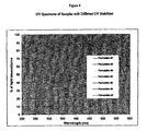
- Additives such as antioxidants, UV-stabilizers, UV-absorbers and others are can stabilize the EVA, but at the same time the additive package can also block UV-wavelengths below 360 nanometers (nm).
- Photovoltaic module efficiency depends on photovoltaic cell efficiency and the sun light wavelength passing through the encapsulant.
- One of the most fundamental limitations on the efficiency of a solar cell is the band gap of its semi-conducting material, i.e., the energy required to boost an electron from the bound valence band into the mobile conduction band. Photons with less energy than the band gap pass through the module without being absorbed. Photons with energy higher than the band gap are absorbed, but their excess energy is wasted (dissipated as heat).
- "tandem" cells or multi-junction cells are used to broaden the wavelength range for energy conversion.
- the band gap of the semi-conductive materials is different than that of mono-crystalline silicon.
- These photovoltaic cells will convert light into electricity for wavelength below 360 nm.
- an encapsulant that can absorb wavelengths below 360 nm is needed to maintain the PV module efficiency.
- US-B-6,320,116 and 6,586,271 teach another important property of these polymeric materials, particularly those materials used in the construction of solar cell modules.
- This property is thermal creep resistance, i.e., resistance to the permanent deformation of a polymer over a period of time as a result of temperature.
- Thermal creep resistance generally, is directly proportional to the melting temperature of a polymer.
- Solar cell modules designed for use in architectural application often need to show excellent resistance to thermal creep at temperatures of 90°C or higher.
- EVA crosslinking the polymeric material is often necessary to give it higher thermal creep resistance.
- Crosslinking particularly chemical crosslinking, while addressing one problem, e.g., thermal creep, can create other problems.
- EVA a common polymeric material used in the construction of solar cell modules and which has a rather low melting point
- EVA a common polymeric material used in the construction of solar cell modules and which has a rather low melting point
- an organic peroxide initiator While this addresses the thermal creep problem, it creates a corrosion problem, i.e., total crosslinking is seldom, if ever, fully achieved and this leaves residual peroxide in the EVA. This remaining peroxide can promote oxidation and degradation of the EVA polymer and/or electronic device, e.g., through the release of acetic acid over the life of the electronic device module.
- organic peroxide to EVA requires careful temperature control to avoid premature crosslinking.
- thermoplasticity i.e., the ability to be softened, molded and formed.
- the polymeric material is to be used as a backskin layer in a frameless module, then it should exhibit thermoplasticity during lamination as described in US-B-5,741,370 . This thermoplasticity, however, must not be obtained at the expense of effective thermal creep resistance.
- the invention is an electronic device module comprising:
- the module can further comprise one or more other components, such as one or more glass cover sheets, and in these embodiments, the polymeric material usually is located between the electronic device and the glass cover sheet in a sandwich configuration. If the polymeric material is applied as a film to the surface of the glass cover sheet opposite the electronic device, then the surface of the film that is in contact with that surface of the glass cover sheet can be smooth or uneven, e.g., embossed or textured.
- the polyolefin copolymer is an ethylene/ ⁇ -olefin copolymer.
- the polymeric material can fully encapsulate the electronic device, or it can be in intimate contact with only a portion of it, e.g., laminated to one face surface of the device.
- the polymeric material can further comprise a scorch inhibitor, and depending upon the application for which the module is intended, the chemical composition of the copolymer and other factors, the copolymer can remain uncrosslinked or be crosslinked. If crosslinked, then it is crosslinked such that it contains less than 70 percent xylene soluble extractables as measured by ASTM 2765-95.
- the invention is the electronic device module as described in the embodiment above except that the polymeric material in intimate contact with at least one surface of the electronic device is a co-extruded material in which at least one outer skin layer (i) does not contain peroxide for crosslinking, and (ii) is the surface which comes into intimate contact with the module.
- this outer skin layer exhibits good adhesion to glass.
- This outer skin of the co-extruded material can comprise any one of a number of different polymers, but is typically the same polymer as the polymer of the peroxide-containing layer but without the peroxide.
- the extruded product comprises at least three layers in which the skin layer in contact with the electronic module is without peroxide, and the peroxide-containing layer is a core layer.
- the invention is a method of manufacturing an electronic device, the method comprising the steps of:
- the module further comprises at least one translucent cover layer disposed apart from one face surface of the device, and the polymeric material is interposed in a sealing relationship between the electronic device and the cover layer.
- "In a sealing relationship" and like terms mean that the polymeric material adheres well to both the cover layer and the electronic device, typically to at least one face surface of each, and that it binds the two together with little, if any, gaps or spaces between the two module components (other than any gaps or spaces that may exist between the polymeric material and the cover layer as a result of the polymeric material applied to the cover layer in the form of an embossed or textured film, or the cover layer itself is embossed or textured).
- the polymeric material can further comprise a scorch inhibitor
- the method can optionally include a step in which the copolymer is crosslinked, e.g., either contacting the electronic device and/or glass cover sheet with the polymeric material under crosslinking conditions, or exposing the module to crosslinking conditions after the module is formed such that the polyolefin copolymer contains less than 70 percent xylene soluble extractables as measured by ASTM 2765-95.
- Crosslinking conditions include heat (e.g., a temperature of at least 160°C), radiation (e.g., at least 15 mega-rad if by E-beam, or 0.05 joules/cm 2 if by UV light), moisture (e.g., a relative humidity of at least 50%), etc.
- heat e.g., a temperature of at least 160°C
- radiation e.g., at least 15 mega-rad if by E-beam, or 0.05 joules/cm 2 if by UV light
- moisture e.g., a relative humidity of at least 50%
- the electronic device is encapsulated, i.e., fully engulfed or enclosed, within the polymeric material.
- the glass cover sheet is treated with a silane coupling agent, e.g., (-amino propyl tri-ethoxy silane.
- the polymeric material further comprises a graft polymer to enhance its adhesive property relative to the one or both of the electronic device and glass cover sheet.
- the graft polymer is made in situ simply by grafting the polyolefin copolymer with an unsaturated organic compound that contains a carbonyl group, e.g., maleic anhydride.
- the polyolefin copolymers useful in the practice of this invention have a density of less than 0.90, preferably less than 0.89, more preferably less than 0.885, even more preferably less than 0.88 and even more preferably less than 0.875, g/cm 3 .
- the polyolefin copolymers typically have a density greater than 0.85, and more preferably greater than 0.86, g/cm 3 . Density is measured by the procedure of ASTM D-792.
- Low density polyolefin copolymers are generally characterized as amorphous, flexible and having good optical properties, e.g., high transmission of visible and UV-light and low haze.
- the polyolefin copolymers useful in the practice of this invention have a 2% secant modulus of less than 150, preferably less than 140, more preferably less than 120 and even more preferably less than 100, MPa as measured by the procedure of ASTM D-882-02.
- the polyolefin copolymers typically have a 2% secant modulus of greater than zero, but the lower the modulus, the better the copolymer is adapted for use in this invention.
- the secant modulus is the slope of a line from the origin of a stress-strain diagram and intersecting the curve at a point of interest, and it is used to describe the stiffness of a material in the inelastic region of the diagram.
- Low modulus polyolefin copolymers are particularly well adapted for use in this invention because they provide stability under stress, e.g., less prone to crack upon stress or shrinkage.
- a single site catalyst such as a metallocene catalyst or constrained geometry catalyst
- the melting point is less than 95°C.
- the melting point is measured by differential scanning calorimetry (DSC) as described, for example, in US-B-5,783,638 .
- Polyolefin copolymers with a low melting point often exhibit desirable flexibility and thermoplasticity properties useful in the fabrication of the modules of this invention.
- the polyolefin copolymers useful in the practice of this invention include ethylene/ ⁇ -olefin interpolymers having an ⁇ -olefin content of between 15, preferably at least 20 and even more preferably at least 25, wt% based on the weight of the interpolymer. These interpolymers typically have an ⁇ -olefin content of less than 50, preferably less than 45, more preferably less than 40 and even more preferably less than 35, wt% based on the weight of the interpolymer.
- the ⁇ -olefin content is measured by 13 C nuclear magnetic resonance (NMR) spectroscopy using the procedure described in Randall ( Rev. Macromol. Chem. Phys., C29 (2&3) ). Generally, the greater the ⁇ -olefin content of the interpolymer, the lower the density and the more amorphous the interpolymer, and this translates into desirable physical and chemical properties for the protective polymer component of the module.
- the ⁇ -olefin is preferably a C 3-20 linear, branched or cyclic ⁇ -olefin.
- the term interpolymer refers to a polymer made from at least two monomers. It includes, for example, copolymers, terpolymers and tetrapolymers.
- Examples of C 3-20 ⁇ -olefins include propene, 1-butene, 4-methyl-1-pentene, 1-hexene, 1-octene, 1-decene, 1-dodecene, 1-tetradecene, 1-hexadecene, and 1-octadecene.
- the ⁇ -olefins can also contain a cyclic structure such as cyclohexane or cyclopentane, resulting in an ⁇ -olefin such as 3-cyclohexyl-1-propene (allyl cyclohexane) and vinyl cyclohexane.
- a cyclic structure such as cyclohexane or cyclopentane
- an ⁇ -olefin such as 3-cyclohexyl-1-propene (allyl cyclohexane) and vinyl cyclohexane.
- cyclic olefins such as norbornene and related olefins, are ⁇ -olefins and can be used in place of some or all of the ⁇ -olefins described above.
- styrene and its related olefins are ⁇ -olefins for purposes of this invention.
- Illustrative polyolefin copolymers include ethylene/propylene, ethylene/butene, ethylene/1-hexene, ethylene/1-octene, ethylene/styrene, and the like.
- EAA Ethylene/acrylic acid
- EMA ethylene/methacrylic acid
- ethylene/acrylate or methacrylate ethylene/vinyl acetate and the like are not polyolefin copolymers of this invention.
- Illustrative terpolymers include ethylene/propylene/1-octene, ethylene/propylene/butene, ethylene/butene/1-octene, and ethylene/butene/styrene.
- the copolymers can be random or blocky.
- VLDPE very low density polyethylene
- FLEXOMER® ethylene/1-hexene polyethylene made by The Dow Chemical Company
- homogeneously branched, linear ethylene/ ⁇ -olefin copolymers e.g. TAFMER® by Mitsui Petrochemicals Company Limited and EXACT® by Exxon Chemical Company
- homogeneously branched, substantially linear ethylene/ ⁇ -olefin polymers e.g., AFFINITY® and ENGAGE® polyethylene available from The Dow Chemical Company.
- the more preferred polyolefin copolymers are the homogeneously branched linear and substantially linear ethylene copolymers.
- the substantially linear ethylene copolymers are especially preferred, and are more fully described in US-B-5,272,236 , 5,278,272 and 5,986,028 .
- the polyolefin copolymers useful in the practice of this invention also include propylene, butene and other alkene-based copolymers, e.g., copolymers comprising a majority of units derived from propylene and a minority of units derived from another ⁇ -olefin (including ethylene).
- Exemplary polypropylenes useful in the practice of this invention include the VERSIFY® polymers available from The Dow Chemical Company, and the VISTAMAXX® polymers available from ExxonMobil Chemical Company.
- Blends of any of the above olefinic interpolymers can also be used in this invention, and the polyolefin copolymers can be blended or diluted with one or more other polymers to the extent that the polymers are (i) miscible with one another, (ii) the other polymers have little, if any, impact on the desirable properties of the polyolefin copolymer, e.g., optics and low modulus, and (iii) the polyolefin copolymers of this invention constitute at least 70, preferably at least 75 and more preferably at least 80, weight percent of the blend.
- EVA copolymer can be one of the diluting polymers.
- the polyolefin copolymers useful in the practice of this invention optionally have a Tg of less than -35, preferably less than -40, more preferably less than -45 and even more preferably less than -50, °C as measured by differential scanning calorimetry (DSC) using the procedure of ASTM D-3418-03.
- the polyolefin copolymers used in the practice of this invention also have a melt index (MI as measured by the procedure of ASTM D-1238 (190°C/2.16kg) of less than 100, preferably less than 75, more preferably less than 50 and even more preferably less than 35, g/10 minutes.
- the typical minimum MI is about 1, and more typically it is about 5.
- the polyolefin copolymers useful in the practice of this invention optionally have an SCBDI (Short Chain Branch Distribution Index) or CDBI (Composition Distribution Branch Index) is defined as the weight percent of the polymer molecules having comonomer content within 50 percent of the median total molar comonomer content.
- the CDBI of a polymer is readily calculated from data obtained from techniques known in the art, such as, for example, temperature rising elution fractionation (abbreviated herein as "TREF") as described, for example, in Wild et al, Journal of Polymer Science, Poly. Phys.Ed., Vol. 20, p. 441 (1982 ), or as described in US-B-4,798,081 and 5,008,204 .
- the SCBDI or CDBI for the polyolefin copolymers used in the practice of this present invention is typically greater than 50, preferably greater than 60, more preferably greater than 70, even more preferably greater than 80, and most preferably greater than 90 percent.
- the polymeric material used in the practice of this invention has at least one, preferably at least three, even more preferably at least four and still more preferably at least five, of the following properties: (a) a density of less than 0.90 g/cm 3 , (b) a 2% secant modulus of less than 150 megaPascal (MPa) as measured by ASTM D-882-02), (c) a melt point of less than 95°C, preferably (d) an ⁇ -olefin content of at least 15 and less than 50 wt% based on the weight of the polymer, preferably (e) a Tg of less than -35°C, and preferably (f) a SCBDI of at least 50.
- the polyolefin copolymers used in the practice of this invention have at least the (a), (b) and (c) properties, preferably at least the (a), (b), (c) and (d) properties, and more preferably at least the (a), (b), (c), (d) and (e) properties.
- Preferred polyolefin polymers are the Affinity® and Engage® polyethylene of The Dow Chemical Company.
- these copolymers are typically cured or crosslinked at the time of contact or after, usually shortly after, the module has been constructed.
- Crosslinking is important to the performance of the copolymer in its function to protect the electronic device from the environment. Specifically, crosslinking enhances the thermal creep resistance of the copolymer and durability of the module in terms of heat, impact and solvent resistance.
- Crosslinking can be effected by any one of a number of different methods, e.g., by the use of thermally activated initiators, e.g., peroxides and azo compounds; photoinitiators, e.g., benzophenone; radiation techniques including sunlight, UV light, E-beam and x-ray; vinyl silane, e.g., vinyl tri-ethoxy or vinyl tri-methoxy silane; and moisture cure.
- thermally activated initiators e.g., peroxides and azo compounds
- photoinitiators e.g., benzophenone
- radiation techniques including sunlight, UV light, E-beam and x-ray
- vinyl silane e.g., vinyl tri-ethoxy or vinyl tri-methoxy silane
- moisture cure e.g., moisture cure.
- the free radical initiators used in the practice of this invention include any thermally activated compound that is relatively unstable and easily breaks into at least two radicals.
- Representative of this class of compounds are the peroxides, particularly the organic peroxides, and the azo initiators.
- the free radical initiators used as crosslinking agents the dialkyl peroxides and diperoxyketal initiators are preferred. These compounds are described in the Encyclopedia of Chemical Technology, 3rd edition, Vol. 17, pp 27-90. (1982 ).
- the preferred initiators are: dicumyl peroxide, di-t-butyl peroxide, t-butyl cumyl peroxide, 2,5-dimethyl-2,5-di(t-butylperoxy)-hexane, 2,5-dimethyl2,5-di(t-amylperoxy)-hexane, 2,5-dimethyl-2,5-di(t-butylperoxy)hexyne-3, 2,5-dimethyl2,5-di(t-amylperoxy)hexyne-3, ⁇ , ⁇ -di[(t-butylperoxy)-isopropyl]-benzene, di-t-amyl peroxide, 1,3,5-tri-[(t-butylperoxy)-isopropyl]benzene, 1,3-dimethyl-3-(t-butylperoxy)butanol, 1,3-dimethyl-3-
- the preferred initiators are: 1,1-di(t-butylperoxy)-3,3,5-trimethylcyclohexane, 1,1-di(t-butylperoxy)cyclohexane n-butyl, 4,4-di(t-amylperoxy)valerate, ethyl 3,3-di(t-butylperoxy)butyrate, 2,2-di(t-amylperoxy)propane, 3,6,6,9,9-pentamethyl-3-ethoxycarbonylmethyl-1,2,4,5-tetraoxacyclononane, n-butyl-4,4-bis(t-butylperoxy)-valerate, ethyl-3,3-di(t-amylperoxy)-butyrate and mixtures of two or more of these initiators.
- peroxide initiators e.g., 00-t-butyl-0-hydrogen-monoperoxysuccinate; 00-t-amyl-0-hydrogen-monoperoxysuccinate and/or azo initiators e.g., 2,2'-azobis-(2-acetoxypropane)
- azo initiators e.g., 2,2'-azobis-(2-acetoxypropane
- suitable azo compounds include those described in US-B-3,862,107 and 4,129,531 .
- Mixtures of two or more free radical initiators may also be used together as the initiator within the scope of this invention.
- free radicals can form from shear energy, heat or radiation.
- the amount of peroxide or azo initiator present in the crosslinkable compositions of this invention can vary widely, but the minimum amount is that sufficient to afford the desired range of crosslinking.
- the minimum amount of initiator is typically at least 0.05, preferably at least 0.1 and more preferably at least 0.25, wt% based upon the weight of the polymer or polymers to be crosslinked.
- the maximum amount of initiator used in these compositions can vary widely, and it is typically determined by such factors as cost, efficiency and degree of desired crosslinking desired.
- the maximum amount is typically less than 10, preferably less than 5 and more preferably less than 3, wt% based upon the weight of the polymer or polymers to be crosslinked.
- Free radical crosslinking initiation via electromagnetic radiation e.g., sunlight, ultraviolet (UV) light, infrared (IR) radiation, electron beam, beta-ray, gamma-ray, x-ray and neutron rays, may also be employed. Radiation is believed to affect crosslinking by generating polymer radicals, which may combine and crosslink.
- electromagnetic radiation e.g., sunlight, ultraviolet (UV) light, infrared (IR) radiation, electron beam, beta-ray, gamma-ray, x-ray and neutron rays
- UV radiation ultraviolet
- IR radiation infrared
- electron beam beta-ray
- beta-ray beta-ray
- gamma-ray gamma-ray
- x-ray and neutron rays may also be employed. Radiation is believed to affect crosslinking by generating polymer radicals, which may combine and crosslink.
- Elemental sulfur may be used as a crosslinking agent for diene containing polymers such as EPDM and polybutad
- the amount of radiation used to cure the copolymer will vary with the chemical composition of the copolymer, the composition and amount of initiator, if any, the nature of the radiation, and the like, but a typical amount of UV light is at least 0.05, more typically at about 0.1 and even more typically at least 0.5, Joules/cm 2 , and a typical amount of E-beam radiation is at least 0.5, more typically at least 1 and even more typically at least 1.5, megarads.
- photoinitiators include organic carbonyl compounds such as such as benzophenone, benzanthrone, benzoin and alkyl ethers thereof, 2,2-dicthoxyacetophenone, 2,2-dimethoxy, 2 phenylacetophenone, p-phenoxy dichloroacetophenone, 2-hydroxycyclohexylphenone, 2-hydroxyisopropylphenone, and 1-phenylpropanedione-2-(ethoxy carboxyl) oxime.
- organic carbonyl compounds such as such as benzophenone, benzanthrone, benzoin and alkyl ethers thereof, 2,2-dicthoxyacetophenone, 2,2-dimethoxy, 2 phenylacetophenone, p-phenoxy dichloroacetophenone, 2-hydroxycyclohexylphenone, 2-hydroxyisopropylphenone, and 1-phenylpropanedione-2-(ethoxy carboxyl) oxime.
- These initiators are used in known manner
- hydrolysis/condensation catalysts include Lewis acids such as dibutyltin dilaurate, dioctyltin dilaurate, stannous octonoate, and hydrogen sulfonates such as sulfonic acid.
- Free radical crosslinking coagents include multifunctional vinyl monomers and polymers, triallyl cyanurate and trimethylolpropane trimethacrylate, divinyl benzene, acrylates and methacrylates of polyols, allyl alcohol derivatives, and low molecular weight polybutadiene.
- Sulfur crosslinking promoters include benzothiazyl disulfide, 2-mercaptobenzothiazole, copper dimethyldithiocarbamate, dipentamethylene thiuram tetrasulfide, tetrabutylthiuram disulfide, tetramethylthiuram disulfide and tetramethylthiuram monosulfide.
- the minimum amount of coagent is typically at least 0.05, preferably at least 0.1 and more preferably at least 0.5, wt% based upon the weight of the polymer or polymers to be crosslinked.
- the maximum amount of coagent used in these compositions can vary widely, and it is typically determined by such factors as cost, efficiency and degree of desired crosslinking desired.
- the maximum amount is typically less than 10, preferably less than 5 and more preferably less than 3, wt% based upon the weight of the polymer or polymers to be crosslinked.
- thermally activated free radical initiators to promote crosslinking, i.e., curing, of thermoplastic materials is that they may initiate premature crosslinking, i.e., scorch, during compounding and/or processing prior to the actual phase in the overall process in which curing is desired.
- scorch occurs when the time-temperature relationship results in a condition in which the free radical initiator undergoes thermal decomposition which, in turn, initiates a crosslinking reaction that can create gel particles in the mass of the compounded polymer. These gel particles can adversely impact the homogeneity of the final product.
- excessive scorch can so reduce the plastic properties of the material that it cannot be efficiently processed with the likely possibility that the entire batch will be lost.
- One method of minimizing scorch is the incorporation of scorch inhibitors into the compositions.
- British patent 1,535,039 discloses the use of organic hydroperoxides as scorch inhibitors for peroxide-cured ethylene polymer compositions.
- US-B-3,751,378 discloses the use of N-nitroso diphenylamine or N,N'-dinitroso-paraphenylamine as scorch retardants incorporated into a polyfunctional acrylate crosslinking monomer for providing long Mooney scorch times in various copolymer formulations.
- US-B-3,202,648 discloses the use of nitrites such as isoamyl nitrite, tert-decyl nitrite and others as scorch inhibitors for polyethylene.
- US-B-3,954,907 discloses the use of monomeric vinyl compounds as protection against scorch.
- US-B-3,335,124 describes the use of aromatic amines, phenolic compounds, mercaptothiazole compounds, bis(N,N-disubstituted-thiocarbamoyl) sulfides, hydroquinones and dialkyldithiocarbamate compounds.
- US-B-4,632,950 discloses the use of mixtures of two metal salts of disubstituted dithiocarbamic acid in which one metal salt is based on copper.
- One commonly used scorch inhibitor for use in free radical, particularly peroxide, initiator-containing compositions is 4-hydroxy-2,2,6,6-tetramethylpiperidin-1-oxyl also known as nitroxyl 2, or NR 1, or 4-oxypiperidol, or tanol, or tempol, or tmpn, or probably most commonly, 4-hydroxy-TEMPO or even more simply, h-TEMPO.
- 4-hydroxy-TEMPO minimizes scorch by "quenching" free radical crosslinking of the crosslinkable polymer at melt processing temperatures.
- the preferred amount of scorch inhibitor used in the compositions of this invention will vary with the amount and nature of the other components of the composition, particularly the free radical initiator, but typically the minimum amount of scorch inhibitor used in a system of polyolefin copolymer with 1.7 weight percent (wt%) peroxide is at least 0.01, preferably at least 0.05, more preferably at least 0.1 and most preferably at least 0.15, wt% based on the weight of the polymer.
- the maximum amount of scorch inhibitor can vary widely, and it is more a function of cost and efficiency than anything else.
- the typical maximum amount of scorch inhibitor used in a system of polyolefin copolymer with 1.7 wt% peroxide does not exceed 2, preferably does not exceed 1.5 and more preferably does not exceed 1, wt% based on the weight of the copolymer.
- silanes include unsaturated silanes that comprise an ethylenically unsaturated hydrocarbyl group, such as a vinyl, allyl, isopropenyl, butenyl, cyclohexenyl or (-(meth)acryloxy allyl group, and a hydrolyzable group, such as, for example, a hydrocarbyloxy, hydrocarbonyloxy, or hydrocarbylamino group.
- hydrolyzable groups include methoxy, ethoxy, formyloxy, acetoxy, proprionyloxy, and alkyl or arylamino groups.
- Preferred silanes are the unsaturated alkoxy silanes which can be grafted onto the polymer. These silanes and their method of preparation are more fully described in US-B-5,266,627 . Vinyl trimethoxy silane, vinyl triethoxy silane, (-(meth)acryloxy propyl trimethoxy silane and mixtures of these silanes are the preferred silane crosslinkers for is use in this invention. If filler is present, then preferably the crosslinker includes vinyl triethoxy silane.
- the amount of silane crosslinker used in the practice of this invention can vary widely depending upon the nature of the polyolefin copolymer, the silane, the processing conditions, the grafting efficiency, the ultimate application, and similar factors, but typically at least 0.5, preferably at least 0.7, parts per hundred resin wt% is used based on the weight of the copolymer. Considerations of convenience and economy are usually the two principal limitations on the maximum amount of silane crosslinker used in the practice of this invention, and typically the maximum amount of silane crosslinker does not exceed 5, preferably it does not exceed 2, wt% based on the weight of the copolymer.
- the silane crosslinker is grafted to the polyolefin copolymer by any conventional method, typically in the presence of a free radical initiator e.g. peroxides and azo compounds, or by ionizing radiation, etc.
- a free radical initiator e.g. peroxides and azo compounds, or by ionizing radiation, etc.
- Organic initiators are preferred, such as any of those described above, e.g., the peroxide and azo initiators.
- the amount of initiator can vary, but it is typically present in the amounts described above for the crosslinking of the polyolefin copolymer.
- one preferred method is blending the two with the initiator in the first stage of a reactor extruder, such as a Buss kneader.
- the grafting conditions can vary, but the melt temperatures are typically between 160 and 260 °C, preferably between 190 and 230 °C, depending upon the residence time and the half life of the initiator.
- the polymeric material further comprises a graft polymer to enhance the adhesion to one or more glass cover sheets to the extent that these sheets are components of the electronic device module.
- the graft polymer can be any graft polymer compatible with the polyolefin copolymer of the polymeric material and which does not significantly compromise the performance of the polyolefin copolymer as a component of the module, typically the graft polymer is a graft polyolefin polymer and more typically, a graft polyolefin copolymer that is of the same composition as the polyolefin copolymer of the polymeric material.
- This graft additive is typically made in situ simply by subjecting the polyolefin copolymer to grafting reagents and grafting conditions such that at least a portion of the polyolefin copolymer is grafted with the grafting material.
- Any unsaturated organic compound containing at least one ethylenic unsaturation (e.g., at least one double bond), at least one carbonyl group (—C O), and that will graft to a polymer, particularly a polyolefin polymer and more particularly to a polyolefin copolymer, can be used as the grafting material in this embodiment of the invention.
- Representative of compounds that contain at least one carbonyl group are the carboxylic acids, anhydrides, esters and their salts, both metallic and nonmetallic.
- the organic compound contains ethylenic unsaturation conjugated with a carbonyl group.
- Representative compounds include maleic, fumaric, acrylic, methacrylic, itaconic, crotonic, ⁇ -methyl crotonic, and cinnamic acid and their anhydride, ester and salt derivatives, if any.
- Maleic anhydride is the preferred unsaturated organic compound containing at least one ethylenic unsaturation and at least one carbonyl group.
- the unsaturated organic compound content of the graft polymer is at least 0.01 wt %, and preferably at least 0.05 wt %, based on the combined weight of the polymer and the organic compound.
- the maximum amount of unsaturated organic compound content can vary to convenience, but typically it does not exceed 10 wt%, preferably it docs not exceed 5 wt%, and more preferably it does not exceed 2 wt%.
- the unsaturated organic compound can be grafted to the polymer by any known technique, such as those taught in US-B-3,236,917 and 5,194,509 .
- the polymer is introduced into a two-roll mixer and mixed at a temperature of 60°C.
- the unsaturated organic compound is then added along with a free radical initiator, such as, for example, benzoyl peroxide, and the components are mixed at 30°C until the grafting is completed.
- a free radical initiator such as, for example, benzoyl peroxide
- the polymeric materials of this invention can comprise other additives as well.
- such other additives include UV-stabilizers and processing stabilizers such as trivalent phosphorus compounds.
- the UV-stabilizers arc useful in lowering the wavelength of electromagnetic radiation that can be absorbed by a PV module (e.g., to less than 360 nm), and include hindered phenols such as Cyasorb UV2908 and hindered amines such as Cyasorb UV 3529, Hostavin N30, Univil 4050, Univin 5050, Chimassorb UV 119, Chimassorb 944 LD, Tinuvin 622 LD and the like.
- the phosphorus compounds include phosphonites (PEPQ) and phosphites (Weston 399, TNPP, P-168 and Doverphos 9228).
- the amount of UV-stabilizer is typically from 0.1 to 0.8%, and preferably from 0.2 to 0.5%.
- the amount of processing stabilizer is typically from 0.02 to 0.5%, and preferably from 0.05 to 0.15%.
- Still other additives include, but are not limited to, antioxidants (e.g., hindered phenolics (e.g., Irganox® 1010 made by Ciba Geigy Corp.), cling additives, e.g., PIB, anti-blocks, anti-slips, pigments and fillers (clear if transparency is important to the application).
- antioxidants e.g., hindered phenolics (e.g., Irganox® 1010 made by Ciba Geigy Corp.
- cling additives e.g., PIB, anti-blocks, anti-slips, pigments and fillers (clear if transparency is important to the application).
- In-process additives e.g. calcium stearate, water, etc., may also be used.
- the polymeric materials of this invention are used to construct electronic device modules in the same manner and using the same amounts as the encapsulant materials known in the art, e.g., such as those taught in US-B-6,586,271 , US Patent Application Publication US2001/0045229 A1 , WO 99/05206 and WO 99/04971 . These materials can be used as "skins" for the electronic device, i.e., applied to one or both face surfaces of the device, or as an encapsulant in which the device is totally enclosed within the material.
- the polymeric material is applied to the device by one or more lamination techniques in which a layer of film formed from the polymeric material is applied first to one face surface of the device, and then to the other face surface of the device.
- the polymeric material can be extruded in molten form onto the device and allowed to congeal on the device.
- the polymeric materials of this invention exhibit good adhesion for the face surfaces of the device.
- the electronic device module comprises (i) at least one electronic device, typically a plurality of such devices arrayed in a linear or planar pattern, (ii) at least one glass cover sheet, typically a glass cover sheet over both face surfaces of the device, and (iii) at least one polymeric material.
- the polymeric material is typically disposed between the glass cover sheet and the device, and the polymeric material exhibits good adhesion to both the device and the sheet.
- the polymeric material exhibits good, typically excellent, transparency for that radiation, e.g., transmission rates in excess of 90, preferably in excess of 95 and even more preferably in excess of 97, percent as measured by UV-vis spectroscopy (measuring absorbance in the wavelength range of 250-1200 nanometers.
- An alternative measure of transparency is the internal haze method of ASTM D-1003-00. If transparency is not a requirement for operation of the electronic device, then the polymeric material can contain opaque filler and/or pigment.
- rigid PV module 10 comprises photovoltaic cell 11 surrounded or encapsulated by transparent protective layer or encapsulant 12 comprising a polyolefin copolymer used in the practice of this invention.
- Glass cover sheet 13 covers a front surface of the portion of the transparent protective layer disposed over PV cell 11.
- Backskin layer 14 need not be transparent if the surface of the PV cell to which it is opposed is not reactive to sunlight.
- protective layer 12 encapsulates PV cell 11.
- Typical thicknesses for protective layer 12 are in the range of 0.125 to 2 millimeters (mm), and for the glass cover sheet and backskin layers in the range of 0.125 to 1.25 mm.
- the thickness of the electronic device can also vary widely.
- flexible PV module 20 comprises thin film photovoltaic 21 over-lain by transparent protective layer or encapsulant 22 comprising a polyolefin copolymer used in the practice of this invention.
- Glazing/top layer 23 covers a front surface of the portion of the transparent protective layer disposed over thin film PV 21.
- Backskin layer 24 need not be transparent if the surface of the thin film cell which it is supporting is not reactive to sunlight.
- protective layer 21 does not encapsulate thin film PV 21.
- the overall thickness of a typical rigid or flexible PV cell module will typically be in the range of 5 to 50 mm.
- protective layer 14 is formed by first extruding a polyolefin copolymer over and onto the top surface of the PV cell and either simultaneously with or subsequent to the extrusion of this first extrusion, extruding the same, or different, polyolefin copolymer over and onto the back surface of the cell.
- the glass cover sheet and backskin layer can be attached in any convenient manner, e.g., extrusion, lamination, etc., to the protective layer, with or without an adhesive.
- Either or both external surfaces, i.e., the surfaces opposite the surfaces in contact with the PV cell, of the protective layer can be embossed or otherwise treated to enhance adhesion to the glass and backskin layers.
- the module of Figure 2 can be constructed in a similar manner, except that the backskin layer is attached to the PV cell directly, with or without an adhesive, either prior or subsequent to the attachment of the protective layer to the PV cell.
- a monolayer 15 mil (380 ⁇ m) thick protective film is made from a blend comprising 80 wt% of ENGAGE® 8400 polyethylene (ethylene/1-octene, 30 MI, 0.87 g/cm 3 ), 20 wt% of a maleic anhydride (MAH) modified ethylene/1-octene copolymer (ENGAGE® 8400 polyethylene grafted at a level of about 1 wt% MAH, and having a post-modified MI of about 1.25 g/10min and a density of about 0.87 g/cm 3 ), 1.5 wt% of Lupersol® 101, 0.8 wt% of tri-allyl cyanurate, 0.1 wt% of Chimassorb® 944, 0.2 wt% of Naugard® P, and 0.3 wt% of Cyasorb® UV 531.
- 80 wt% of ENGAGE® 8400 polyethylene ethylene/1-octene, 30 MI, 0.87 g/cm 3
- the melt temperature during film formation is kept below about 120°C to avoid premature crosslinking of the film during extrusion.
- This film is then used to prepare a solar cell module.
- the film is laminated at a temperature of about 150°C to a superstrate, e.g., a glass cover sheet, and the front surface of a solar cell, and then to the back surface of the solar cell and a backskin material, e.g., another glass cover sheet or any other substrate.
- the protective film is then subjected to conditions that will ensure that the film is substantially crosslinked.
- Example 1 The procedure of Example 1 is repeated except that the blend comprised 90 wt% ENGAGE® 8400 (ethylene/1-octene, 30 Mi, 0.87 g/cm 3 ) and 10wt% of a maleic anhydride (MAH) modified ethylene/1-octene (ENGAGE® 8400 polyethylene grafted at a level of about 1 wt% MAH, and having a post-modified MI of about 1.25 g/10min and a density of about 0.87 g/cm 3 ), and the melt temperature during film formation was kept below about 120°C to avoid premature crosslinking of the film during extrusion.
- MAH maleic anhydride
- Example 1 The procedure of Example 1 is repeated except that the blend comprised 97 wt% ENGAGE® 8400 (ethylene/1-octene, 30 Mi, 0.87 g/cm 3 ) and 3 wt% of vinyl silane (no maleic anhydride modified ENGAGE® 8400 polyethylene), and the melt temperature during film formation was kept below about 120°C to avoid premature crosslinking of the film during extrusion.
- 97 wt% ENGAGE® 8400 ethylene/1-octene, 30 Mi, 0.87 g/cm 3
- vinyl silane no maleic anhydride modified ENGAGE® 8400 polyethylene
- the adhesion with glass is measured using silane-treated glass.
- the procedure of glass treatment is adapted it from a procedure in Gelest, Inc. "Silanes and Silicones, Catalog 3000 A”.
- acetic acid is added to 200 mL of 95% ethanol in order to make the solution slightly acidic.
- 4 mL of 3-aminopropyltrimethoxysilane is added with stirring, making a ⁇ 2% solution of silane.
- the solution sits for 5 minutes to allow for hydrolysis to begin, and then it is transferred to a glass dish.
- Each plate is immersed in the solution for 2 minutes with gentle agitation, removed, rinsed briefly with 95% ethanol to remove excess silane, and allowed to drain.
- the plates are cured in an oven at 110°C for 15 minutes.
- they are soaked in a 5% solution of sodium bicarbonate for 2 minutes in order to convert the acetate salt of the amine to the free amine. They are rinsed with water, wiped dry with a paper towel, and air dried at room temperature overnight.
- the method for testing the adhesion strength between the polymer and glass is the 180 peel test. This is not an ASTM standard test, but it is used to examine the adhesion with glass for PV modules.
- the test sample is prepared by placing uncured film on the top of the glass, and then curing the film under pressure in a compression molding machine. The molded sample is held under laboratory conditions for two days before the test. The adhesion strength is measured with an Instron machine. The loading rate is 2 in/min, and the test is run under ambient conditions. The test is stopped after a stable peel region is observed (about 2 inches; 5cm). The ratio of peel load over film width is reported as the adhesion strength.
- tensile and dynamic mechanical analysis (DMA) methods are evaluated using tensile and dynamic mechanical analysis (DMA) methods.
- the tensile test is run under ambient conditions with a load rate of 2 in/min.
- the DMA method is conducted from -100 to 120 °C.
- the optical properties are determined as follows: Percent of light transmittance is measured by UV-vis spectroscopy. It measures the absorbance in the wavelength of 250 nm to 1200 nm. The internal haze is measured using ASTM D1003-61.
- the polyolefin copolymer provided much superior elongation to break, tensile strength and elongation to break at 85°C as compared with the EVA polymer with little diminution in adhesion to glass strength and optics.
- the adhesion with glass is measured using silane-treated glass.
- the procedure of glass treatment is adapted it from a procedure in Gelest, Inc. "Silanes and Silicones, Catalog 3000 A":
- the optical properties are determined as follows: Percent of light transmittance is measured by UV-vis spectroscopy. It measures the absorbance in the wavelength of 250 nm to 1200 nm. The internal haze is measured using ASTM D1003-61.
- ENGAGETM 8200 ethylene/1-octene random copolymer (made by The Dow Chemical Company) is used in this example. Its density is 0.87 g/cm 3 , the melt index is 5 g/10 minutes (measured based on standard ASTM D1238, condition 190°C/2.16kg). There is 100 ppm of antioxidant, Irganox 1076, in the resin. Several additives are selected to add functionality or improve the long term stability of the resin. They are UV absorbent Cyasorb UV 531, UV-stabilizer Chimassorb 944 LD, antioxidant Tinuvin 622 LD, vinyltrimethoxysilane (VTMS), and peroxide Luperox-101. The formulation in weight percent is described in Table 3.
- ENGAGE 8200 pellets are dried at 40°C for overnight in a dryer.
- the pellets and the additives are dry mixed and placed in a drum and tumbled for 30 minutes.
- the silane and peroxide are poured into the drum and tumbled for another 15 minutes.
- the well-mixed materials are fed to a film extruder for film casting.
- An 18-19 mil (460-480 ⁇ m) thick film is saved at 5.3 feet per minute (ft/min).
- the film sample is sealed in an aluminum bag to avoid UV-irradiation and moisture.
- UV-visible spectrometer Perkin Elmer UV-Vis 950 with scanning double monochromator and integrating sphere accessory. Samples used for this analysis have a thickness of 15 mils (380 ⁇ m).
- Figure 3 shows the UV-visible spectra of the film and a comparison film, i.e., commercial incumbent film ETIMEX 485 which is made from ethylene vinyl acetate (about 33 wt% VA content) for the same application. Both films show above 90% of transmittance over the wavelength range from 400 to 1100 nm.
- the method used for the adhesion test is a 180° peel test. This is not an ASTM standard test, but has been used to examine the adhesion with glass for photovoltaic module and auto laminate glass applications.
- the test sample is prepared by placing the film on the top of glass under pressure in a compression molding machine.
- the desired adhesion width is 1.0 inch (2.54cm).
- the frame used to hold the sample is 5 inches (12.7cm) by 5 inches (12.7cm).
- a Teflon tm sheet is placed between the glass and the material to separate the glass and polymer for the purpose of test setup.
- the conditions for the glass/film sample preparation are:
- the adhesion strength is measured with a materials testing system (Instron 5581). The loading rate is 2 inches (5cm) /minutes and the tests are run at ambient conditions (24°C and 50% RH). A stable peel region is needed (about 2 inches; 5cm) to evaluate the adhesion to glass. The ratio of peel load in the stable peel region over the film width is reported as the adhesion strength.
- the water vapor transmission rate is measured using a permeation analysis instrument (Mocon Permatran W Model 101 K). All WVTR units are in grams per square meter per day (g/(m 2 -day) measured at 38°C and 50°C and 100% RH, an average of two specimens.
- the commercial EVA film as described above is also tested to compare the moisture barrier properties.
- the inventive film and the commercial film thickness are 15 mils (380 ⁇ m), and both films are cured at 160°C for 30 minutes. The results of WVTR testing are reported in Table 6.
- the composition of the A layers does not require drying.
- the composition of the core layer i.e., the B layer, comprises the same components and is prepared in the same manner as the composition described in Example 3.
- ENGAGE tm 8400 resin is replaced with a blend of (i) polyolefin polymer having a melt index (MI) of 5 and a density of 0.868 g/cm 3 , and (ii) AMPLIFY GR 216 resin (a MAH-modified ethylene/1-octene resin grafted at a level of about 1 wt% MAH, and having a post-modified MI of about 1.25 g/10min and a density of about 0.87 g/cm 3 . Both compositions are reported in Table 7.
Description
- This invention relates to electronic device modules. In one aspect, the invention relates to electronic device modules comprising an electronic device, e.g., a solar or photovoltaic (PV) cell, and a protective polymeric material while in another aspect, the invention relates to electronic device modules in which the protective polymeric material is a polyolefin polymer with at least one of (a) a density of less than 0.90 grams per cubic centimeter (g/cm3), (b) a low modulus, (c) a melt point less than 95°C, (d) an α-olefin content between 15-50 weight percent (wt%) based on the weight of the copolymer, (c) a glass transition temperature (Tg) of less than -35°C, and (f) a short chain branch distribution index (SCBDI or CDBI) of 50 or greater. In yet another aspect, the invention relates to a method of making an electronic device module.
- Polymeric materials are commonly used in the manufacture of modules comprising one or more electronic devices including, but not limited to, solar cells (also known as photovoltaic cells), liquid crystal panels, electro-luminescent devices and plasma display units. The modules often comprise an electronic device in combination with one or more substrates, e.g., one or more glass cover sheets, often positioned between two substrates in which one or both of the substrates comprise glass, metal, plastic, rubber or another material. The polymeric materials are typically used as the encapsulant or sealant for the module or depending upon the design of the module, as a skin layer component of the module, e.g., a backskin in a solar cell module. Typical polymeric materials for these purposes include silicone resins, epoxy resins, polyvinyl butyral resins, cellulose acetate, ethylene-vinyl acetate copolymer (EVA) and ionomers.
- United States Patent Application Publication
2001/0045229 A1 identifies a number of properties desirable in any polymeric material that is intended for use in the construction of an electronic device module. These properties include (i) protecting the device from exposure to the outside environment, e.g., moisture and air, particularly over long periods of time (ii) protecting against mechanical shock, (iii) strong adhesion to the electronic device and substrates, (iv) easy processing, including sealing, (v) good transparency, particularly in applications in which light or other electromagnetic radiation is important, e.g., solar cell modules, (vi) short cure times with protection of the electronic device from mechanical stress resulting from polymer shrinkage during cure, (vii) high electrical resistance with little, if any, electrical conductance, and (viii) low cost. No one polymeric material delivers maximum performance on all of these properties in any particular application, and usually trade-offs are made to maximize the performance of properties most important to a particular application, e.g., transparency and protection against the environment, at the expense of properties secondary in importance to the application, e.g., cure time and cost. Combinations of polymeric materials are also employed, either as a blend or as separate components of the module. - EVA copolymers with a high content (28 to 35 wt%) of units derived from the vinyl acetate monomer are commonly used to make encapsulant film for use in photovoltaic (PV) modules. See, for example,
WO 95/22844 99/04971 99/05206 2004/055908 . EVA resins are typically stabilized with ultra-violet (UV) light additives, and they are typically crosslinked during the solar cell lamination process using peroxides to improve heat and creep resistance to a temperature between 80 and 90 °C. However, EVA resins are less than ideal PV cell encapsulating film material for several reasons. For example, EVA film progressively darkens in intense sunlight due to the EVA resin chemically degrading under the influence of UV light. This discoloration can result in a greater than 30% loss in power output of the solar module after as little as four years of exposure to the environment. EVA resins also absorb moisture and are subject to decomposition. - Moreover and as noted above, EVA resins are typically stabilized with UV additives and crosslinked during the solar cell lamination and/or encapsulation process using peroxides to improve heat resistance and creep at high temperature, e.g., 80 to 90 °C. However, because of the C=O bonds in the EVA molecular structure that absorbs UV radiation and the presence of residual peroxide crosslinking agent in the system after curing, an additive package is used to stabilize the EVA against UV-induced degradation. The residual peroxide is believed to be the primary oxidizing reagent responsible for the generation of chromophores (e.g.,
US-B-6,093,757 ). Additives such as antioxidants, UV-stabilizers, UV-absorbers and others are can stabilize the EVA, but at the same time the additive package can also block UV-wavelengths below 360 nanometers (nm). - Photovoltaic module efficiency depends on photovoltaic cell efficiency and the sun light wavelength passing through the encapsulant. One of the most fundamental limitations on the efficiency of a solar cell is the band gap of its semi-conducting material, i.e., the energy required to boost an electron from the bound valence band into the mobile conduction band. Photons with less energy than the band gap pass through the module without being absorbed. Photons with energy higher than the band gap are absorbed, but their excess energy is wasted (dissipated as heat). In order to increase the photovoltaic cell efficiency, "tandem" cells or multi-junction cells are used to broaden the wavelength range for energy conversion. In addition, in many of the thin film technologies such as amorphous silicon, cadmium telluride, or copper indium gallium selenide, the band gap of the semi-conductive materials is different than that of mono-crystalline silicon. These photovoltaic cells will convert light into electricity for wavelength below 360 nm. For these photovoltaic cells, an encapsulant that can absorb wavelengths below 360 nm is needed to maintain the PV module efficiency.
-
US-B-6,320,116 and6,586,271 teach another important property of these polymeric materials, particularly those materials used in the construction of solar cell modules. This property is thermal creep resistance, i.e., resistance to the permanent deformation of a polymer over a period of time as a result of temperature. Thermal creep resistance, generally, is directly proportional to the melting temperature of a polymer. Solar cell modules designed for use in architectural application often need to show excellent resistance to thermal creep at temperatures of 90°C or higher. For materials with low melting temperatures, e.g., EVA, crosslinking the polymeric material is often necessary to give it higher thermal creep resistance. - Crosslinking, particularly chemical crosslinking, while addressing one problem, e.g., thermal creep, can create other problems. For example, EVA, a common polymeric material used in the construction of solar cell modules and which has a rather low melting point, is often crosslinked using an organic peroxide initiator. While this addresses the thermal creep problem, it creates a corrosion problem, i.e., total crosslinking is seldom, if ever, fully achieved and this leaves residual peroxide in the EVA. This remaining peroxide can promote oxidation and degradation of the EVA polymer and/or electronic device, e.g., through the release of acetic acid over the life of the electronic device module. Moreover, the addition of organic peroxide to EVA requires careful temperature control to avoid premature crosslinking.
- Another potential problem with peroxide-initiated crosslinking is the buildup of crosslinked material on the metal surfaces of the process equipment. During extrusion runs, high residence time is experienced at all metal flow surfaces. Over longer periods of extrusion time, crosslinked material can form at the metal surfaces and require cleaning of the equipment. The current practice to minimize gel formation, i.e., this crosslinking of polymer on the metal surfaces of the processing equipment, is to use low processing temperatures which, in turn, reduces the production rate of the extruded product.
- One other property that can be important in the selection of a polymeric material for use in the manufacture of an electronic device module is thermoplasticity, i.e., the ability to be softened, molded and formed. For example, if the polymeric material is to be used as a backskin layer in a frameless module, then it should exhibit thermoplasticity during lamination as described in
US-B-5,741,370 . This thermoplasticity, however, must not be obtained at the expense of effective thermal creep resistance. - In one embodiment, the invention is an electronic device module comprising:
- A. At least one electronic device, and
- B. A polymeric material in intimate contact with at least one surface of the electronic device, the polymeric material comprising (1) a polyolefin copolymer having (a) a density of less than 0.90 g/cm3, (b) a 2% secant modulus of less than 150 megaPascal (MPa) as measured by ASTM D-882-02), (c) a melt point of less than 95°C, optionally (d) an α-olefin content of at least 15 and less than 50 wt% based on the weight of the polymer, optionally (e) a Tg of less than -35°C, and optionally (f) a SCBDI of at least 50, (2) a vinyl silane in an amount of at least about 0.1 wt% based on the weight of the copolymer, (3) optionally, a free radical initiator, e.g., a peroxide or azo compound, or a photoinitiator, e.g., benzophenone, in an amount of at least 0.05 wt% based on the weight of the copolymer, and (4) optionally, a co-agent in an amount of at least 0.05 wt% based upon the weight of the copolymer.
- The module can further comprise one or more other components, such as one or more glass cover sheets, and in these embodiments, the polymeric material usually is located between the electronic device and the glass cover sheet in a sandwich configuration. If the polymeric material is applied as a film to the surface of the glass cover sheet opposite the electronic device, then the surface of the film that is in contact with that surface of the glass cover sheet can be smooth or uneven, e.g., embossed or textured.
- Typically, the polyolefin copolymer is an ethylene/α-olefin copolymer. The polymeric material can fully encapsulate the electronic device, or it can be in intimate contact with only a portion of it, e.g., laminated to one face surface of the device. Optionally, the polymeric material can further comprise a scorch inhibitor, and depending upon the application for which the module is intended, the chemical composition of the copolymer and other factors, the copolymer can remain uncrosslinked or be crosslinked. If crosslinked, then it is crosslinked such that it contains less than 70 percent xylene soluble extractables as measured by ASTM 2765-95.
- In another embodiment, the invention is the electronic device module as described in the embodiment above except that the polymeric material in intimate contact with at least one surface of the electronic device is a co-extruded material in which at least one outer skin layer (i) does not contain peroxide for crosslinking, and (ii) is the surface which comes into intimate contact with the module. Typically, this outer skin layer exhibits good adhesion to glass. This outer skin of the co-extruded material can comprise any one of a number of different polymers, but is typically the same polymer as the polymer of the peroxide-containing layer but without the peroxide. This embodiment of the invention allows for the use of higher processing temperatures which, in turn, allows for faster production rates without unwanted gel formation in the encapsulating polymer due to extended contact with the metal surfaces of the processing equipment. In another embodiment, the extruded product comprises at least three layers in which the skin layer in contact with the electronic module is without peroxide, and the peroxide-containing layer is a core layer.
- In another embodiment the invention is a method of manufacturing an electronic device, the method comprising the steps of:
- A. Providing at least one electronic device, and
- B. Contacting at least one surface of the electronic device with a polymeric material comprising (1) a polyolefin copolymer having (a) a density of less than 0.90 g/cm3, (b) a 2% secant modulus of less than 150 megaPascal (MPa) as measured by ASTM D-882-02), and (c) a melt point of less than 95°C, optionally (d) an α-olefin content of at least 15 and less than 50 wt% based on the weight of the polymer, optionally (e) a Tg of less than -35°C, and optionally (f) a SCBDI of at least 50, (2) a vinyl silane, e.g., vinyl tri-ethoxy silane or vinyl tri-methoxy silane, in an amount of at least 0.1 wt% based on the weight of the copolymer, (3) optionally, a free radical initiator, e.g., a peroxide or azo compound, or a photoinitiator, e.g., benzophenone, in an amount of at least 0.05 wt% based on the weight of the copolymer, and (4) optionally, a co-agent in an amount of at least 0.05 wt% based on the weight of the copolymer.
- In a variant on this method embodiment, the module further comprises at least one translucent cover layer disposed apart from one face surface of the device, and the polymeric material is interposed in a sealing relationship between the electronic device and the cover layer. "In a sealing relationship" and like terms mean that the polymeric material adheres well to both the cover layer and the electronic device, typically to at least one face surface of each, and that it binds the two together with little, if any, gaps or spaces between the two module components (other than any gaps or spaces that may exist between the polymeric material and the cover layer as a result of the polymeric material applied to the cover layer in the form of an embossed or textured film, or the cover layer itself is embossed or textured).
- Moreover, in this method embodiment, the polymeric material can further comprise a scorch inhibitor, and the method can optionally include a step in which the copolymer is crosslinked, e.g., either contacting the electronic device and/or glass cover sheet with the polymeric material under crosslinking conditions, or exposing the module to crosslinking conditions after the module is formed such that the polyolefin copolymer contains less than 70 percent xylene soluble extractables as measured by ASTM 2765-95. Crosslinking conditions include heat (e.g., a temperature of at least 160°C), radiation (e.g., at least 15 mega-rad if by E-beam, or 0.05 joules/cm2 if by UV light), moisture (e.g., a relative humidity of at least 50%), etc.
- In another variant on this method embodiment, the electronic device is encapsulated, i.e., fully engulfed or enclosed, within the polymeric material. In another variant on these embodiments, the glass cover sheet is treated with a silane coupling agent, e.g., (-amino propyl tri-ethoxy silane. In yet another variant on these embodiments, the polymeric material further comprises a graft polymer to enhance its adhesive property relative to the one or both of the electronic device and glass cover sheet. Typically the graft polymer is made in situ simply by grafting the polyolefin copolymer with an unsaturated organic compound that contains a carbonyl group, e.g., maleic anhydride.
-
-
Figure 1 is a schematic of one embodiment of an electronic device module of this invention, i.e., a rigid photovoltaic (PV) module. -
Figure 2 is a schematic of another embodiment of an electronic device module of this invention, i.e., a flexible PV module. -
Figure 3 is the UV spectrum of the experimental and commercial films report in Example 4. -
Figure 4 is UV spectrum of the samples prepared and reported in Example 6. - The polyolefin copolymers useful in the practice of this invention have a density of less than 0.90, preferably less than 0.89, more preferably less than 0.885, even more preferably less than 0.88 and even more preferably less than 0.875, g/cm3. The polyolefin copolymers typically have a density greater than 0.85, and more preferably greater than 0.86, g/cm3. Density is measured by the procedure of ASTM D-792. Low density polyolefin copolymers are generally characterized as amorphous, flexible and having good optical properties, e.g., high transmission of visible and UV-light and low haze.
- The polyolefin copolymers useful in the practice of this invention have a 2% secant modulus of less than 150, preferably less than 140, more preferably less than 120 and even more preferably less than 100, MPa as measured by the procedure of ASTM D-882-02. The polyolefin copolymers typically have a 2% secant modulus of greater than zero, but the lower the modulus, the better the copolymer is adapted for use in this invention. The secant modulus is the slope of a line from the origin of a stress-strain diagram and intersecting the curve at a point of interest, and it is used to describe the stiffness of a material in the inelastic region of the diagram. Low modulus polyolefin copolymers are particularly well adapted for use in this invention because they provide stability under stress, e.g., less prone to crack upon stress or shrinkage.
- The polyolefin copolymers useful in the practice of this invention and that are preferably made with a single site catalyst such as a metallocene catalyst or constrained geometry catalyst, have a melting point of less than 95, preferably less than 90, more preferably less than 85, even more preferably less than 80 and still more preferably less than 75, °C. For polyolefin copolymers made with multi-site catalysts, e.g., Zeigler-Natta and Phillips catalysts, the melting point is less than 95°C. The melting point is measured by differential scanning calorimetry (DSC) as described, for example, in
US-B-5,783,638 . Polyolefin copolymers with a low melting point often exhibit desirable flexibility and thermoplasticity properties useful in the fabrication of the modules of this invention. - The polyolefin copolymers useful in the practice of this invention include ethylene/α-olefin interpolymers having an α-olefin content of between 15, preferably at least 20 and even more preferably at least 25, wt% based on the weight of the interpolymer. These interpolymers typically have an α-olefin content of less than 50, preferably less than 45, more preferably less than 40 and even more preferably less than 35, wt% based on the weight of the interpolymer. The α-olefin content is measured by 13C nuclear magnetic resonance (NMR) spectroscopy using the procedure described in Randall (Rev. Macromol. Chem. Phys., C29 (2&3)). Generally, the greater the α-olefin content of the interpolymer, the lower the density and the more amorphous the interpolymer, and this translates into desirable physical and chemical properties for the protective polymer component of the module.
- The α-olefin is preferably a C3-20 linear, branched or cyclic α-olefin. The term interpolymer refers to a polymer made from at least two monomers. It includes, for example, copolymers, terpolymers and tetrapolymers. Examples of C3-20 α-olefins include propene, 1-butene, 4-methyl-1-pentene, 1-hexene, 1-octene, 1-decene, 1-dodecene, 1-tetradecene, 1-hexadecene, and 1-octadecene. The α-olefins can also contain a cyclic structure such as cyclohexane or cyclopentane, resulting in an α-olefin such as 3-cyclohexyl-1-propene (allyl cyclohexane) and vinyl cyclohexane. Although not α-olefins in the classical sense of the term, for purposes of this invention certain cyclic olefins, such as norbornene and related olefins, are α-olefins and can be used in place of some or all of the α-olefins described above. Similarly, styrene and its related olefins (for example, α-methylstyrene, etc.) are α-olefins for purposes of this invention. Acrylic and methacrylic acid and their respective ionomers, and acrylates and methacrylates, however, are not α-olefins for purposes of this invention. Illustrative polyolefin copolymers include ethylene/propylene, ethylene/butene, ethylene/1-hexene, ethylene/1-octene, ethylene/styrene, and the like. Ethylene/acrylic acid (EAA), ethylene/methacrylic acid (EMA), ethylene/acrylate or methacrylate, ethylene/vinyl acetate and the like are not polyolefin copolymers of this invention. Illustrative terpolymers include ethylene/propylene/1-octene, ethylene/propylene/butene, ethylene/butene/1-octene, and ethylene/butene/styrene. The copolymers can be random or blocky.
- More specific examples of olefinic interpolymers useful in this invention include very low density polyethylene (VLDPE) (e.g., FLEXOMER® ethylene/1-hexene polyethylene made by The Dow Chemical Company), homogeneously branched, linear ethylene/α-olefin copolymers (e.g. TAFMER® by Mitsui Petrochemicals Company Limited and EXACT® by Exxon Chemical Company), and homogeneously branched, substantially linear ethylene/α-olefin polymers (e.g., AFFINITY® and ENGAGE® polyethylene available from The Dow Chemical Company). The more preferred polyolefin copolymers are the homogeneously branched linear and substantially linear ethylene copolymers. The substantially linear ethylene copolymers are especially preferred, and are more fully described in
US-B-5,272,236 ,5,278,272 and5,986,028 . - The polyolefin copolymers useful in the practice of this invention also include propylene, butene and other alkene-based copolymers, e.g., copolymers comprising a majority of units derived from propylene and a minority of units derived from another α-olefin (including ethylene). Exemplary polypropylenes useful in the practice of this invention include the VERSIFY® polymers available from The Dow Chemical Company, and the VISTAMAXX® polymers available from ExxonMobil Chemical Company.
- Blends of any of the above olefinic interpolymers can also be used in this invention, and the polyolefin copolymers can be blended or diluted with one or more other polymers to the extent that the polymers are (i) miscible with one another, (ii) the other polymers have little, if any, impact on the desirable properties of the polyolefin copolymer, e.g., optics and low modulus, and (iii) the polyolefin copolymers of this invention constitute at least 70, preferably at least 75 and more preferably at least 80, weight percent of the blend. Although not favored, EVA copolymer can be one of the diluting polymers.
- The polyolefin copolymers useful in the practice of this invention optionally have a Tg of less than -35, preferably less than -40, more preferably less than -45 and even more preferably less than -50, °C as measured by differential scanning calorimetry (DSC) using the procedure of ASTM D-3418-03. Moreover, typically the polyolefin copolymers used in the practice of this invention also have a melt index (MI as measured by the procedure of ASTM D-1238 (190°C/2.16kg) of less than 100, preferably less than 75, more preferably less than 50 and even more preferably less than 35, g/10 minutes. The typical minimum MI is about 1, and more typically it is about 5.
- The polyolefin copolymers useful in the practice of this invention optionally have an SCBDI (Short Chain Branch Distribution Index) or CDBI (Composition Distribution Branch Index) is defined as the weight percent of the polymer molecules having comonomer content within 50 percent of the median total molar comonomer content. The CDBI of a polymer is readily calculated from data obtained from techniques known in the art, such as, for example, temperature rising elution fractionation (abbreviated herein as "TREF") as described, for example, in Wild et al, Journal of Polymer Science, Poly. Phys.Ed., Vol. 20, p. 441 (1982), or as described in
US-B-4,798,081 and5,008,204 . The SCBDI or CDBI for the polyolefin copolymers used in the practice of this present invention is typically greater than 50, preferably greater than 60, more preferably greater than 70, even more preferably greater than 80, and most preferably greater than 90 percent. - The polymeric material used in the practice of this invention has at least one, preferably at least three, even more preferably at least four and still more preferably at least five, of the following properties: (a) a density of less than 0.90 g/cm3, (b) a 2% secant modulus of less than 150 megaPascal (MPa) as measured by ASTM D-882-02), (c) a melt point of less than 95°C, preferably (d) an α-olefin content of at least 15 and less than 50 wt% based on the weight of the polymer, preferably (e) a Tg of less than -35°C, and preferably (f) a SCBDI of at least 50. The polyolefin copolymers used in the practice of this invention have at least the (a), (b) and (c) properties, preferably at least the (a), (b), (c) and (d) properties, and more preferably at least the (a), (b), (c), (d) and (e) properties. Preferred polyolefin polymers are the Affinity® and Engage® polyethylene of The Dow Chemical Company.
- Due to the low density and modulus of the polyolefin copolymers used in the practice of this invention, these copolymers are typically cured or crosslinked at the time of contact or after, usually shortly after, the module has been constructed. Crosslinking is important to the performance of the copolymer in its function to protect the electronic device from the environment. Specifically, crosslinking enhances the thermal creep resistance of the copolymer and durability of the module in terms of heat, impact and solvent resistance. Crosslinking can be effected by any one of a number of different methods, e.g., by the use of thermally activated initiators, e.g., peroxides and azo compounds; photoinitiators, e.g., benzophenone; radiation techniques including sunlight, UV light, E-beam and x-ray; vinyl silane, e.g., vinyl tri-ethoxy or vinyl tri-methoxy silane; and moisture cure.
- The free radical initiators used in the practice of this invention include any thermally activated compound that is relatively unstable and easily breaks into at least two radicals. Representative of this class of compounds are the peroxides, particularly the organic peroxides, and the azo initiators. Of the free radical initiators used as crosslinking agents, the dialkyl peroxides and diperoxyketal initiators are preferred. These compounds are described in the Encyclopedia of Chemical Technology, 3rd edition, Vol. 17, pp 27-90. (1982).
- In the group of dialkyl peroxides, the preferred initiators are: dicumyl peroxide, di-t-butyl peroxide, t-butyl cumyl peroxide, 2,5-dimethyl-2,5-di(t-butylperoxy)-hexane, 2,5-dimethyl2,5-di(t-amylperoxy)-hexane, 2,5-dimethyl-2,5-di(t-butylperoxy)hexyne-3, 2,5-dimethyl2,5-di(t-amylperoxy)hexyne-3, α,α-di[(t-butylperoxy)-isopropyl]-benzene, di-t-amyl peroxide, 1,3,5-tri-[(t-butylperoxy)-isopropyl]benzene, 1,3-dimethyl-3-(t-butylperoxy)butanol, 1,3-dimethyl-3-(t-amylperoxy)butanol and mixtures of two or more of these initiators.
- In the group of diperoxyketal initiators, the preferred initiators are: 1,1-di(t-butylperoxy)-3,3,5-trimethylcyclohexane, 1,1-di(t-butylperoxy)cyclohexane n-butyl, 4,4-di(t-amylperoxy)valerate,
ethyl 3,3-di(t-butylperoxy)butyrate, 2,2-di(t-amylperoxy)propane, 3,6,6,9,9-pentamethyl-3-ethoxycarbonylmethyl-1,2,4,5-tetraoxacyclononane, n-butyl-4,4-bis(t-butylperoxy)-valerate, ethyl-3,3-di(t-amylperoxy)-butyrate and mixtures of two or more of these initiators. - Other peroxide initiators, e.g., 00-t-butyl-0-hydrogen-monoperoxysuccinate; 00-t-amyl-0-hydrogen-monoperoxysuccinate and/or azo initiators e.g., 2,2'-azobis-(2-acetoxypropane), may also be used to provide a crosslinked polymer matrix. Other suitable azo compounds include those described in
US-B-3,862,107 and4,129,531 . Mixtures of two or more free radical initiators may also be used together as the initiator within the scope of this invention. In addition, free radicals can form from shear energy, heat or radiation. - The amount of peroxide or azo initiator present in the crosslinkable compositions of this invention can vary widely, but the minimum amount is that sufficient to afford the desired range of crosslinking. The minimum amount of initiator is typically at least 0.05, preferably at least 0.1 and more preferably at least 0.25, wt% based upon the weight of the polymer or polymers to be crosslinked. The maximum amount of initiator used in these compositions can vary widely, and it is typically determined by such factors as cost, efficiency and degree of desired crosslinking desired. The maximum amount is typically less than 10, preferably less than 5 and more preferably less than 3, wt% based upon the weight of the polymer or polymers to be crosslinked.
- Free radical crosslinking initiation via electromagnetic radiation, e.g., sunlight, ultraviolet (UV) light, infrared (IR) radiation, electron beam, beta-ray, gamma-ray, x-ray and neutron rays, may also be employed. Radiation is believed to affect crosslinking by generating polymer radicals, which may combine and crosslink. The Handbook of Polymer Foams and Technology, supra, at pp. 198-204, provides additional teachings. Elemental sulfur may be used as a crosslinking agent for diene containing polymers such as EPDM and polybutadiene. The amount of radiation used to cure the copolymer will vary with the chemical composition of the copolymer, the composition and amount of initiator, if any, the nature of the radiation, and the like, but a typical amount of UV light is at least 0.05, more typically at about 0.1 and even more typically at least 0.5, Joules/cm2, and a typical amount of E-beam radiation is at least 0.5, more typically at least 1 and even more typically at least 1.5, megarads.
- If sunlight or UV light is used to effect cure or crosslinking, then typically and preferably one or more photoinitiators arc employed. Such photoinitiators include organic carbonyl compounds such as such as benzophenone, benzanthrone, benzoin and alkyl ethers thereof, 2,2-dicthoxyacetophenone, 2,2-dimethoxy, 2 phenylacetophenone, p-phenoxy dichloroacetophenone, 2-hydroxycyclohexylphenone, 2-hydroxyisopropylphenone, and 1-phenylpropanedione-2-(ethoxy carboxyl) oxime. These initiators are used in known manners and in known quantities, e.g., typically at least 0.05, more typically at least 0.1 and even more typically 0.5, wt% based on the weight of the copolymer.
- If moisture, i.e., water, is used to effect cure or crosslinking, then typically and preferably one or more hydrolysis/condensation catalysts are employed. Such catalysts include Lewis acids such as dibutyltin dilaurate, dioctyltin dilaurate, stannous octonoate, and hydrogen sulfonates such as sulfonic acid.
- Free radical crosslinking coagents, i.e. promoters or co-initiators, include multifunctional vinyl monomers and polymers, triallyl cyanurate and trimethylolpropane trimethacrylate, divinyl benzene, acrylates and methacrylates of polyols, allyl alcohol derivatives, and low molecular weight polybutadiene. Sulfur crosslinking promoters include benzothiazyl disulfide, 2-mercaptobenzothiazole, copper dimethyldithiocarbamate, dipentamethylene thiuram tetrasulfide, tetrabutylthiuram disulfide, tetramethylthiuram disulfide and tetramethylthiuram monosulfide.
- These coagents are used in known amounts and known ways. The minimum amount of coagent is typically at least 0.05, preferably at least 0.1 and more preferably at least 0.5, wt% based upon the weight of the polymer or polymers to be crosslinked. The maximum amount of coagent used in these compositions can vary widely, and it is typically determined by such factors as cost, efficiency and degree of desired crosslinking desired. The maximum amount is typically less than 10, preferably less than 5 and more preferably less than 3, wt% based upon the weight of the polymer or polymers to be crosslinked.
- One difficulty in using thermally activated free radical initiators to promote crosslinking, i.e., curing, of thermoplastic materials is that they may initiate premature crosslinking, i.e., scorch, during compounding and/or processing prior to the actual phase in the overall process in which curing is desired. With conventional methods of compounding, such as milling, Banbury, or extrusion, scorch occurs when the time-temperature relationship results in a condition in which the free radical initiator undergoes thermal decomposition which, in turn, initiates a crosslinking reaction that can create gel particles in the mass of the compounded polymer. These gel particles can adversely impact the homogeneity of the final product. Moreover, excessive scorch can so reduce the plastic properties of the material that it cannot be efficiently processed with the likely possibility that the entire batch will be lost.
- One method of minimizing scorch is the incorporation of scorch inhibitors into the compositions. For example, British patent
1,535,039 US-B-3,751,378 discloses the use of N-nitroso diphenylamine or N,N'-dinitroso-paraphenylamine as scorch retardants incorporated into a polyfunctional acrylate crosslinking monomer for providing long Mooney scorch times in various copolymer formulations.US-B-3,202,648 discloses the use of nitrites such as isoamyl nitrite, tert-decyl nitrite and others as scorch inhibitors for polyethylene.US-B-3,954,907 discloses the use of monomeric vinyl compounds as protection against scorch.US-B-3,335,124 describes the use of aromatic amines, phenolic compounds, mercaptothiazole compounds, bis(N,N-disubstituted-thiocarbamoyl) sulfides, hydroquinones and dialkyldithiocarbamate compounds.US-B-4,632,950 discloses the use of mixtures of two metal salts of disubstituted dithiocarbamic acid in which one metal salt is based on copper. - One commonly used scorch inhibitor for use in free radical, particularly peroxide, initiator-containing compositions is 4-hydroxy-2,2,6,6-tetramethylpiperidin-1-oxyl also known as
nitroxyl 2, orNR 1, or 4-oxypiperidol, or tanol, or tempol, or tmpn, or probably most commonly, 4-hydroxy-TEMPO or even more simply, h-TEMPO. The addition of 4-hydroxy-TEMPO minimizes scorch by "quenching" free radical crosslinking of the crosslinkable polymer at melt processing temperatures. - The preferred amount of scorch inhibitor used in the compositions of this invention will vary with the amount and nature of the other components of the composition, particularly the free radical initiator, but typically the minimum amount of scorch inhibitor used in a system of polyolefin copolymer with 1.7 weight percent (wt%) peroxide is at least 0.01, preferably at least 0.05, more preferably at least 0.1 and most preferably at least 0.15, wt% based on the weight of the polymer. The maximum amount of scorch inhibitor can vary widely, and it is more a function of cost and efficiency than anything else. The typical maximum amount of scorch inhibitor used in a system of polyolefin copolymer with 1.7 wt% peroxide does not exceed 2, preferably does not exceed 1.5 and more preferably does not exceed 1, wt% based on the weight of the copolymer.
- Any silane that will effectively graft to and crosslink the polyolefin copolymer can be used in the practice of this invention. Suitable silanes include unsaturated silanes that comprise an ethylenically unsaturated hydrocarbyl group, such as a vinyl, allyl, isopropenyl, butenyl, cyclohexenyl or (-(meth)acryloxy allyl group, and a hydrolyzable group, such as, for example, a hydrocarbyloxy, hydrocarbonyloxy, or hydrocarbylamino group. Examples of hydrolyzable groups include methoxy, ethoxy, formyloxy, acetoxy, proprionyloxy, and alkyl or arylamino groups. Preferred silanes are the unsaturated alkoxy silanes which can be grafted onto the polymer. These silanes and their method of preparation are more fully described in
US-B-5,266,627 . Vinyl trimethoxy silane, vinyl triethoxy silane, (-(meth)acryloxy propyl trimethoxy silane and mixtures of these silanes are the preferred silane crosslinkers for is use in this invention. If filler is present, then preferably the crosslinker includes vinyl triethoxy silane. - The amount of silane crosslinker used in the practice of this invention can vary widely depending upon the nature of the polyolefin copolymer, the silane, the processing conditions, the grafting efficiency, the ultimate application, and similar factors, but typically at least 0.5, preferably at least 0.7, parts per hundred resin wt% is used based on the weight of the copolymer. Considerations of convenience and economy are usually the two principal limitations on the maximum amount of silane crosslinker used in the practice of this invention, and typically the maximum amount of silane crosslinker does not exceed 5, preferably it does not exceed 2, wt% based on the weight of the copolymer.
- The silane crosslinker is grafted to the polyolefin copolymer by any conventional method, typically in the presence of a free radical initiator e.g. peroxides and azo compounds, or by ionizing radiation, etc. Organic initiators are preferred, such as any of those described above, e.g., the peroxide and azo initiators. The amount of initiator can vary, but it is typically present in the amounts described above for the crosslinking of the polyolefin copolymer.
- While any conventional method can be used to graft the silane crosslinker to the polyolefin copolymer, one preferred method is blending the two with the initiator in the first stage of a reactor extruder, such as a Buss kneader. The grafting conditions can vary, but the melt temperatures are typically between 160 and 260 °C, preferably between 190 and 230 °C, depending upon the residence time and the half life of the initiator.
- In another embodiment of the invention, the polymeric material further comprises a graft polymer to enhance the adhesion to one or more glass cover sheets to the extent that these sheets are components of the electronic device module. While the graft polymer can be any graft polymer compatible with the polyolefin copolymer of the polymeric material and which does not significantly compromise the performance of the polyolefin copolymer as a component of the module, typically the graft polymer is a graft polyolefin polymer and more typically, a graft polyolefin copolymer that is of the same composition as the polyolefin copolymer of the polymeric material. This graft additive is typically made in situ simply by subjecting the polyolefin copolymer to grafting reagents and grafting conditions such that at least a portion of the polyolefin copolymer is grafted with the grafting material.
- Any unsaturated organic compound containing at least one ethylenic unsaturation (e.g., at least one double bond), at least one carbonyl group (—C=O), and that will graft to a polymer, particularly a polyolefin polymer and more particularly to a polyolefin copolymer, can be used as the grafting material in this embodiment of the invention. Representative of compounds that contain at least one carbonyl group are the carboxylic acids, anhydrides, esters and their salts, both metallic and nonmetallic. Preferably, the organic compound contains ethylenic unsaturation conjugated with a carbonyl group. Representative compounds include maleic, fumaric, acrylic, methacrylic, itaconic, crotonic, α-methyl crotonic, and cinnamic acid and their anhydride, ester and salt derivatives, if any. Maleic anhydride is the preferred unsaturated organic compound containing at least one ethylenic unsaturation and at least one carbonyl group.
- The unsaturated organic compound content of the graft polymer is at least 0.01 wt %, and preferably at least 0.05 wt %, based on the combined weight of the polymer and the organic compound. The maximum amount of unsaturated organic compound content can vary to convenience, but typically it does not exceed 10 wt%, preferably it docs not exceed 5 wt%, and more preferably it does not exceed 2 wt%.
- The unsaturated organic compound can be grafted to the polymer by any known technique, such as those taught in
US-B-3,236,917 and5,194,509 . For example, in the '917 patent the polymer is introduced into a two-roll mixer and mixed at a temperature of 60°C. The unsaturated organic compound is then added along with a free radical initiator, such as, for example, benzoyl peroxide, and the components are mixed at 30°C until the grafting is completed. In the '509 patent, the procedure is similar except that the reaction temperature is higher, e.g., 210 to 300 °C, and a free radical initiator is not used or is used at a reduced concentration. - An alternative and preferred method of grafting is taught in
US-B-4,950,541 by using a twin-screw devolatilizing extruder as the mixing apparatus. The polymer and unsaturated organic compound are mixed and reacted within the extruder at temperatures at which the reactants are molten and in the presence of a free radical initiator. Preferably, the unsaturated organic compound is injected into a zone maintained under pressure within the extruder. - The polymeric materials of this invention can comprise other additives as well. For example, such other additives include UV-stabilizers and processing stabilizers such as trivalent phosphorus compounds. The UV-stabilizers arc useful in lowering the wavelength of electromagnetic radiation that can be absorbed by a PV module (e.g., to less than 360 nm), and include hindered phenols such as Cyasorb UV2908 and hindered amines such as Cyasorb UV 3529, Hostavin N30, Univil 4050, Univin 5050, Chimassorb UV 119, Chimassorb 944 LD, Tinuvin 622 LD and the like. The phosphorus compounds include phosphonites (PEPQ) and phosphites (Weston 399, TNPP, P-168 and Doverphos 9228). The amount of UV-stabilizer is typically from 0.1 to 0.8%, and preferably from 0.2 to 0.5%. The amount of processing stabilizer is typically from 0.02 to 0.5%, and preferably from 0.05 to 0.15%.
- Still other additives include, but are not limited to, antioxidants (e.g., hindered phenolics (e.g., Irganox® 1010 made by Ciba Geigy Corp.), cling additives, e.g., PIB, anti-blocks, anti-slips, pigments and fillers (clear if transparency is important to the application). In-process additives, e.g. calcium stearate, water, etc., may also be used. These and other potential additives are used in the manner and amount as is commonly known in the art.
- The polymeric materials of this invention are used to construct electronic device modules in the same manner and using the same amounts as the encapsulant materials known in the art, e.g., such as those taught in
US-B-6,586,271 , US Patent Application PublicationUS2001/0045229 A1 ,WO 99/05206 WO 99/04971 - In one embodiment, the electronic device module comprises (i) at least one electronic device, typically a plurality of such devices arrayed in a linear or planar pattern, (ii) at least one glass cover sheet, typically a glass cover sheet over both face surfaces of the device, and (iii) at least one polymeric material. The polymeric material is typically disposed between the glass cover sheet and the device, and the polymeric material exhibits good adhesion to both the device and the sheet. If the device requires access to specific forms of electromagnetic radiation, e.g., sunlight, infrared, ultra-violet, etc., then the polymeric material exhibits good, typically excellent, transparency for that radiation, e.g., transmission rates in excess of 90, preferably in excess of 95 and even more preferably in excess of 97, percent as measured by UV-vis spectroscopy (measuring absorbance in the wavelength range of 250-1200 nanometers. An alternative measure of transparency is the internal haze method of ASTM D-1003-00. If transparency is not a requirement for operation of the electronic device, then the polymeric material can contain opaque filler and/or pigment.
- In
Figure 1 ,rigid PV module 10 comprises photovoltaic cell 11 surrounded or encapsulated by transparent protective layer orencapsulant 12 comprising a polyolefin copolymer used in the practice of this invention. Glass cover sheet 13 covers a front surface of the portion of the transparent protective layer disposed over PV cell 11. Backskin or back sheet 14, e.g., a second glass cover sheet or another substrate of any kind, supports a rear surface of the portion of transparentprotective layer 12 disposed on a rear surface of PV cell 11. Backskin layer 14 need not be transparent if the surface of the PV cell to which it is opposed is not reactive to sunlight. In this embodiment,protective layer 12 encapsulates PV cell 11. The thicknesses of these layers, both in an absolute context and relative to one another, arc not critical to this invention and as such, can vary widely depending upon the overall design and purpose of the module. Typical thicknesses forprotective layer 12 are in the range of 0.125 to 2 millimeters (mm), and for the glass cover sheet and backskin layers in the range of 0.125 to 1.25 mm. The thickness of the electronic device can also vary widely. - In
Figure 2 ,flexible PV module 20 comprises thin film photovoltaic 21 over-lain by transparent protective layer or encapsulant 22 comprising a polyolefin copolymer used in the practice of this invention. Glazing/top layer 23 covers a front surface of the portion of the transparent protective layer disposed overthin film PV 21. Flexible backskin or back sheet 24, e.g., a second protective layer or another flexible substrate of any kind, supports the bottom surface ofthin film PV 21. Backskin layer 24 need not be transparent if the surface of the thin film cell which it is supporting is not reactive to sunlight. In this embodiment,protective layer 21 does not encapsulatethin film PV 21. The overall thickness of a typical rigid or flexible PV cell module will typically be in the range of 5 to 50 mm. - The modules described in
Figures 1 and 2 can be constructed by any number of different methods, typically a film or sheet co-extrusion method such as blown-film, modified blown-film, calendaring and casting. In one method and referring toFigure 1 , protective layer 14 is formed by first extruding a polyolefin copolymer over and onto the top surface of the PV cell and either simultaneously with or subsequent to the extrusion of this first extrusion, extruding the same, or different, polyolefin copolymer over and onto the back surface of the cell. Once the protective film is attached the PV cell, the glass cover sheet and backskin layer can be attached in any convenient manner, e.g., extrusion, lamination, etc., to the protective layer, with or without an adhesive. Either or both external surfaces, i.e., the surfaces opposite the surfaces in contact with the PV cell, of the protective layer can be embossed or otherwise treated to enhance adhesion to the glass and backskin layers. The module ofFigure 2 can be constructed in a similar manner, except that the backskin layer is attached to the PV cell directly, with or without an adhesive, either prior or subsequent to the attachment of the protective layer to the PV cell. - The following prophetic examples further illustrate the invention. Unless otherwise indicated, all parts and percentages are by weight.
- A monolayer 15 mil (380µm) thick protective film is made from a blend comprising 80 wt% of ENGAGE® 8400 polyethylene (ethylene/1-octene, 30 MI, 0.87 g/cm3), 20 wt% of a maleic anhydride (MAH) modified ethylene/1-octene copolymer (ENGAGE® 8400 polyethylene grafted at a level of about 1 wt% MAH, and having a post-modified MI of about 1.25 g/10min and a density of about 0.87 g/cm3), 1.5 wt% of Lupersol® 101, 0.8 wt% of tri-allyl cyanurate, 0.1 wt% of Chimassorb® 944, 0.2 wt% of Naugard® P, and 0.3 wt% of Cyasorb® UV 531. The melt temperature during film formation is kept below about 120°C to avoid premature crosslinking of the film during extrusion. This film is then used to prepare a solar cell module. The film is laminated at a temperature of about 150°C to a superstrate, e.g., a glass cover sheet, and the front surface of a solar cell, and then to the back surface of the solar cell and a backskin material, e.g., another glass cover sheet or any other substrate. The protective film is then subjected to conditions that will ensure that the film is substantially crosslinked.
- The procedure of Example 1 is repeated except that the blend comprised 90 wt% ENGAGE® 8400 (ethylene/1-octene, 30 Mi, 0.87 g/cm3) and 10wt% of a maleic anhydride (MAH) modified ethylene/1-octene (ENGAGE® 8400 polyethylene grafted at a level of about 1 wt% MAH, and having a post-modified MI of about 1.25 g/10min and a density of about 0.87 g/cm3), and the melt temperature during film formation was kept below about 120°C to avoid premature crosslinking of the film during extrusion.
- The procedure of Example 1 is repeated except that the blend comprised 97 wt% ENGAGE® 8400 (ethylene/1-octene, 30 Mi, 0.87 g/cm3) and 3 wt% of vinyl silane (no maleic anhydride modified ENGAGE® 8400 polyethylene), and the melt temperature during film formation was kept below about 120°C to avoid premature crosslinking of the film during extrusion.
Formulations and Processing Procedures: - Step 1: Use ZSK-30 extruder with Adhere Screw to compound resin and additive package with or without Amplify.
- Step 2: Dry the material from
Step 2 for 4 hours at 100F maximum (use W&C canister dryers). - Step 3: With material hot from dryer, add melted DiCup + Silane + TAC, tumble blend for 15 min and let soak for 4 hours.
- The adhesion with glass is measured using silane-treated glass. The procedure of glass treatment is adapted it from a procedure in Gelest, Inc. "Silanes and Silicones, Catalog 3000 A".
- Approximately 10 mL of acetic acid is added to 200 mL of 95% ethanol in order to make the solution slightly acidic. Then, 4 mL of 3-aminopropyltrimethoxysilane is added with stirring, making a ~2% solution of silane. The solution sits for 5 minutes to allow for hydrolysis to begin, and then it is transferred to a glass dish. Each plate is immersed in the solution for 2 minutes with gentle agitation, removed, rinsed briefly with 95% ethanol to remove excess silane, and allowed to drain. The plates are cured in an oven at 110°C for 15 minutes. Then, they are soaked in a 5% solution of sodium bicarbonate for 2 minutes in order to convert the acetate salt of the amine to the free amine. They are rinsed with water, wiped dry with a paper towel, and air dried at room temperature overnight.
- The method for testing the adhesion strength between the polymer and glass is the 180 peel test. This is not an ASTM standard test, but it is used to examine the adhesion with glass for PV modules. The test sample is prepared by placing uncured film on the top of the glass, and then curing the film under pressure in a compression molding machine. The molded sample is held under laboratory conditions for two days before the test. The adhesion strength is measured with an Instron machine. The loading rate is 2 in/min, and the test is run under ambient conditions. The test is stopped after a stable peel region is observed (about 2 inches; 5cm). The ratio of peel load over film width is reported as the adhesion strength.
- Several important mechanical properties of the cured films are evaluated using tensile and dynamic mechanical analysis (DMA) methods. The tensile test is run under ambient conditions with a load rate of 2 in/min. The DMA method is conducted from -100 to 120 °C.
- The optical properties are determined as follows: Percent of light transmittance is measured by UV-vis spectroscopy. It measures the absorbance in the wavelength of 250 nm to 1200 nm. The internal haze is measured using ASTM D1003-61.
- The results are reported in Table 2. The EVA is a fully formulated film available from Etimex.
Table 2 Test Results Key Properties EVA 1 Elongation to break (%) 411.7 528.7 STDV* 17.5 43.3 Tensile strength at 85°C (psi) 51.2 118.4 STDV* 8.9 12.7 Elongation to break at 85°C (%) 77.1 146.9 STDV* 16.3 24.7 Adhesion with glass (N/mm) 7 4.5 % of transmittance >97 >97 STDV* 0.1 0.2 Internal Haze 2.8 7.2 STDV* 0.4 1 *STDV = Standard Deviation. - As shown by the data of Table 2, the polyolefin copolymer provided much superior elongation to break, tensile strength and elongation to break at 85°C as compared with the EVA polymer with little diminution in adhesion to glass strength and optics.
- The adhesion with glass is measured using silane-treated glass. The procedure of glass treatment is adapted it from a procedure in Gelest, Inc. "Silanes and Silicones, Catalog 3000 A":
- Approximately 10 mL of acetic acid is added to 200 mL of 95% ethanol in order to make the solution slightly acidic. Then, 4 mL of 3-aminopropyltrimethoxysilane is added with stirring, making a ~2% solution of silane. The solution sits for 5 minutes to allow for hydrolysis to begin, and then it is transferred to a glass dish. Each plate is immersed in the solution for 2 minutes with gentle agritation, removed, rinsed briefly with 95% ethanol to remove excess silane, and allowed to drain. The plates are cured in an oven at 110°C for 15 minutes. Then, they are soaked in a 5% solution of sodium bicarbonate for 2 minutes in order to convert the acetate salt of the amine to the free amine. They are rinsed with water, wiped dry with a paper towel, and air dried at room temperature overnight.
- The optical properties are determined as follows: Percent of light transmittance is measured by UV-vis spectroscopy. It measures the absorbance in the wavelength of 250 nm to 1200 nm. The internal haze is measured using ASTM D1003-61.
- ENGAGE
™ 8200 ethylene/1-octene random copolymer (made by The Dow Chemical Company) is used in this example. Its density is 0.87 g/cm3, the melt index is 5 g/10 minutes (measured based on standard ASTM D1238, condition 190°C/2.16kg). There is 100 ppm of antioxidant, Irganox 1076, in the resin. Several additives are selected to add functionality or improve the long term stability of the resin. They are UV absorbent Cyasorb UV 531, UV-stabilizer Chimassorb 944 LD, antioxidant Tinuvin 622 LD, vinyltrimethoxysilane (VTMS), and peroxide Luperox-101. The formulation in weight percent is described in Table 3.Table 3 Film Formulation Formulation Weight Percent ENGAGE 8200 97.34 Cyasorb UV 531 0.3 Chimassorb 944 LD 0.1 Tinuvin 622 LD 0.1 Irganox-168 0.08 Silane (Dow Coming Z-6300) 2 Luperox-101 0.08 Total 100 - ENGAGE 8200 pellets are dried at 40°C for overnight in a dryer. The pellets and the additives are dry mixed and placed in a drum and tumbled for 30 minutes. Then the silane and peroxide are poured into the drum and tumbled for another 15 minutes. The well-mixed materials are fed to a film extruder for film casting.
- Film is cast on a film line (single screw extruder, 24-inch (0.6 m) width sheet die) and the processing conditions are summarized in Table 4.
Table 4 Process Conditions Sample # RPM Amp Extruder Die Head P psi (MPa)) Zone 1 °F (°C)Zone 2 °F (°C)Zone 3 °F (°C)Adapter (F) Adapter (°C) Die (°C) 1 25 22 2,940 (20.27) 300 (149) 325 (162) 350 (177) 350 (177) 182 140 - An 18-19 mil (460-480 µm) thick film is saved at 5.3 feet per minute (ft/min). The film sample is sealed in an aluminum bag to avoid UV-irradiation and moisture.
- The light transmittance of the film is examined by UV-visible spectrometer (Perkin Elmer UV-Vis 950 with scanning double monochromator and integrating sphere accessory). Samples used for this analysis have a thickness of 15 mils (380µm).
Figure 3 shows the UV-visible spectra of the film and a comparison film, i.e., commercial incumbent film ETIMEX 485 which is made from ethylene vinyl acetate (about 33 wt% VA content) for the same application. Both films show above 90% of transmittance over the wavelength range from 400 to 1100 nm. - The method used for the adhesion test is a 180° peel test. This is not an ASTM standard test, but has been used to examine the adhesion with glass for photovoltaic module and auto laminate glass applications. The test sample is prepared by placing the film on the top of glass under pressure in a compression molding machine. The desired adhesion width is 1.0 inch (2.54cm). The frame used to hold the sample is 5 inches (12.7cm) by 5 inches (12.7cm). A Teflontm sheet is placed between the glass and the material to separate the glass and polymer for the purpose of test setup. The conditions for the glass/film sample preparation are:
- (1) 160°C for 3 minutes at 80 pounds per square inch (psi) (0.55 MPa) (2000 Ibs; 0.9 tonne)
- (2) 160°C for 30 minutes at 320 psi (2.2 MPa) (8000 Ibs; 3.6 tonne)
- (3) Cool to room temperature at 320 psi (2.2 MPa) (8000 Ibs; 3.6 tonne)
- (4) Remove the sample from the chase and allow 48 hours for the material to condition at room temperature before the adhesion test.
- The adhesion strength is measured with a materials testing system (Instron 5581). The loading rate is 2 inches (5cm) /minutes and the tests are run at ambient conditions (24°C and 50% RH). A stable peel region is needed (about 2 inches; 5cm) to evaluate the adhesion to glass. The ratio of peel load in the stable peel region over the film width is reported as the adhesion strength.
- The effect of temperature and moisture on adhesion strength is examined using samples aged in hot water (80°C) for one week. These samples are molded on glass, then immersed in hot water for one week. These samples are then dried under laboratory conditions for two days before the adhesion test. In comparison, the adhesion strength of the same commercial EVA film as described above is also evaluated under the same conditions. The adhesion strength of the experimental film and the commercial sample are shown in Table 5.
Table 5 Tests Results of Adhesion to Glass Sample Information Conditions for Molding on Glass Aging Condition Adhesion Strength (N/mm) Commercial Film (cured) 160°C, one h none 10 Commercial Film (cured) 160°C, one h 80°C in water for one week 1 Inventive Film 160°C, 30 min none >10 (no delamination)* Inventive Film 160°C, 30 min 80°C in water for one week 3 *The sample did not delaminate, but instead began to destroy the film itself. - The water vapor transmission rate is measured using a permeation analysis instrument (Mocon Permatran W Model 101 K). All WVTR units are in grams per square meter per day (g/(m2-day) measured at 38°C and 50°C and 100% RH, an average of two specimens. The commercial EVA film as described above is also tested to compare the moisture barrier properties. The inventive film and the commercial film thickness are 15 mils (380µm), and both films are cured at 160°C for 30 minutes. The results of WVTR testing are reported in Table 6.
Table 6 Summary of WVTR Test Results Film Specimen WVTR at 38°C g/(m2-day) WVTR at 50°C g/(m2-day) Thick mil (µm) Permeation at 38°C (g-mil)/ (m2-day) (g-µm)/(m2-day) Permeation at 50°C (g-mil)/(m2-day) (g-µm)/(m2-day) Commercial Film A 44.52 98.74 16.80 (426.7) 747 (18974) 1660 (42164) B 44.54 99.14 16.60 421.6) 739 (187711) 1646 (41808) avg. 44.53 98.94 16.70 (424.2) 744 (18898) 1652 (41961 ) Inventive Film A 5.62 14.08 18.90 (480.1) 106(2692) 266 (6756) B 5.53 14.07 18.20 (462.3) 101(2565) 256 (6502) avg. 5.57 14.07 18.55 (471.2) 103 (2616) 261 (6629) - Two resins are used to prepare a three-layer A-B-A, co-extruded film for encapsulating an electronic device. The total thickness of the film is 18 mil (460µm). The outer A layers contact the surfaces of the die. The core (B) layer comprises 80 volume percent (vol%) of the sheet, and each outer layer comprises 10 vol% of the sheet. The composition of the A layers does not require drying. The composition of the core layer, i.e., the B layer, comprises the same components and is prepared in the same manner as the composition described in Example 3. In the skin layers, ENGAGEtm 8400 resin is replaced with a blend of (i) polyolefin polymer having a melt index (MI) of 5 and a density of 0.868 g/cm3, and (ii) AMPLIFY GR 216 resin (a MAH-modified ethylene/1-octene resin grafted at a level of about 1 wt% MAH, and having a post-modified MI of about 1.25 g/10min and a density of about 0.87 g/cm3. Both compositions are reported in Table 7.
Table 7 Compositions of the Layers of an A-B-A Layer Film Component Outer Layers (wt%) Core Layer (wt%) ENGAGE 8400 0 94.7 Polyolefin Resin 20 0 AMPLIFYtm GR-2160 79.3 0 TEMPO 0 0.05 Cyasorb UV 531 0.3 0.3 Chimassorb 944 LD 0.1 0.1 Tinuvin 622 LD 0.1 0.1 Naugard P 0.2 0.2 Dicup- R 0 2.0 Trimethoxysilane 0 1.75 Sartomer SR-507 0 0.8 - Two set of samples are prepared to demonstrate that UV absorption can be shifted by using different UV-stabilizers. Engage 8100 polyolefin elastomer (density 0.87 g/cm3, melt index 1), are used and Table 8 reports the formulations with different UV-stabilizers (all amounts are in weight percent). The samples are made using a mixer at a temperature of 190°C for 5 minutes. Thin films with a thickness of 16 mils (410µm) are made using a compressing molding machine. The molding conditions are 10 minutes at 160°C, and then cooling to 24°C in 30 minutes. The UV spectrum is measured using a UV/Vis spectrometer such as a Lambda 950. The UV spectrums of these films are shown in
Figure 4 . The results show that different types (and/or combinations) of UV-stabilizers can allow the absorption of UV radiation at a wavelength below 360 nm.Table 8 ENGAGE 8100 with Different UV-Stabilizers Sample ENGAGE 8100 Absorber UV-531 Cyasorb UV2908 Cyasorb UV3529 Chimassorb UV-119 Chimassorb 944-LD Tinuvin 622- LD 1 100 2 99.7 0.3 3 99.7 0.3 4 99.7 0.3 5 99.7 0.3 6 99.5 0.25 0.25 7 99.85 0.15 - Another set of samples are prepared to examine UV-stability. Again, a polyolefin elastomer, Engage 8100 (density 0.87 g/cm3, melt index 1) is selected for this study. Table 9 reports the formulations designed for encapsulant polymers for photovoltaic modules with different UV-stabilizers, silane and peroxide, and antioxidant. These formulations are designed to lower the UV absorbance and at the same time maintain and improved the long term UV-stability.
- Although the invention has been described in considerable detail through the preceding description and examples, this detail is for the purpose of illustration and is not to be construed as a limitation on the scope of the invention as it is described in the appended claims.
Table 9 ENGAGE 8100 with Different UV-Stabilizers, Silanes. Peroxides and Antioxidants Samples engage 8100 Absorber UV 531 Cyasorb UV 2908 Cyasorb UV 3529 Univil 4050 Doverphos S-9228 Hostavin N30 Chimassorb UV 119 Chimassorb 944 LD Tinuvin 622 LD Westerns 399 Irgafos 166 C 199.8 0.2 C 299.3 0.3 0.1 0.1 0.2 C 399.5 0.3 0.1 0.1 1 99.5 0.5 2 99.5 0.5 3 99.5 0.5 4 99.5 0.5 5 99.7 0.3 0.5 6 99.3 0.7 7 99.5 0.5 8 99.5 0.5 9 99.4 0.3 0.1 0.1 0.1 10 99.3 0.3 0.1 0.1 0.2 11 99.3 0.5 0.2
| Formulation | |
| Sample No. | 1 |
| Engage 8400 (ethylene/1-octene, 30 MI, 0.870 g/cm3.) | 94.7 |
| 4-Hydroxy-TEMPO | 0.05 |
| Cyasorb UV 531 | 0.3 |
| Chimassorb 944 LD | 0.1 |
| Tinuvin 622 LD | 0.1 |
| Naugard P | 0.2 |
| Additives below added via soaking step | |
| Dicup- | 2 |
| Gamma-methacrylo-propyl-trimethoxysilane (Dow Coming Z-6030) | 1.75 |
| Sartomer SR-507 Tri-Allyl Cyanurate (TAC) | 0.8 |
| Total | 100 |
Claims (13)
- An electronic device module comprising:A. At least one electronic device, andB. A polymeric material in intimate contact with at least one surface of the electronic device, the polymeric material comprising:(1) a polyolefin copolymer having (a) a density of less than about 0.90 g/cc, (b) a 2% secant modulus of less than about 150 megaPascal (mPa) as measured by ASTM D-882-02), and (c) a melt point of less than about 95°C, optionally (d) an α-olefin content of at least about 15 and less than about 50 wt% based on the weight of the polymer, optionally (e) a Tg of less than about -35C, and optionally (f) a SCBDI of at least about 50%,(2) a vinyl silane in an amount of at least about 0.1 wt% based on the weight of the copolymer,(3) optionally, a free radical initiator in an amount of at least about 0.05 wt% based on the weight of the copolymer, and(4) optionally, a co-agent in an amount of less than 3% based on the weight of the copolymer.
- A module of Claim 1 in which the free radical initiator is present.
- A module of Claim 2 in which the free radical initiator is a peroxide.
- A module of Claim 2 in which the free radical initiator is a photoinitiator.
- A module of any one of Claims 1 to 4 in which the coagent is present.
- A module of any one of the preceding claims in which the polymeric material is in the form of a monolayer film in intimate contact with at least one face surface of the electronic device.
- A module of any one of the preceding claims in which the polymeric material further comprises a scorch inhibitor in an amount from 0.01 to 1.7 wt%.
- A module of any one of the preceding claims which the polymeric material further comprises a polyolefin polymer grafted with an unsaturated organic compound containing at least one ethylenic unsaturation and at least one carbonyl group.
- A module of Claim 8 in which the unsaturated organic compound is maleic anhydride.
- A module of Claim 1 in which the vinyl silane is at least one of vinyl tri-ethoxy silane and vinyl tri-methoxy silane.
- A module of any one of the preceding claims in which the Polyolefin copolymer is crosslinked such that that the copolymer contains less than 70 percent xylene soluble extractables as measured by ASTM 2765-95.
- A module of any one of the preceding claims further comprising at least one glass cover sheet.
- A module of any one of the preceding claims in which the electronic device is a solar cell.
Applications Claiming Priority (3)
| Application Number | Priority Date | Filing Date | Title |
|---|---|---|---|
| US82632806P | 2006-09-20 | 2006-09-20 | |
| US86596506P | 2006-11-15 | 2006-11-15 | |
| PCT/US2007/078846 WO2008036708A2 (en) | 2006-09-20 | 2007-09-19 | Electronic device module comprising polyolefin copolymer |
Publications (2)
| Publication Number | Publication Date |
|---|---|
| EP2067175A2 EP2067175A2 (en) | 2009-06-10 |
| EP2067175B1 true EP2067175B1 (en) | 2013-03-20 |
Family
ID=38776249
Family Applications (1)
| Application Number | Title | Priority Date | Filing Date |
|---|---|---|---|
| EP07814922A Active EP2067175B1 (en) | 2006-09-20 | 2007-09-19 | Electronic device module comprising polyolefin copolymer |
Country Status (10)
| Country | Link |
|---|---|
| US (2) | US8581094B2 (en) |
| EP (1) | EP2067175B1 (en) |
| JP (2) | JP5778388B2 (en) |
| CN (1) | CN101563786B (en) |
| BR (1) | BRPI0714999B1 (en) |
| CA (1) | CA2663059C (en) |
| MY (1) | MY153286A (en) |
| NO (1) | NO20091120L (en) |
| TW (1) | TWI501410B (en) |
| WO (1) | WO2008036708A2 (en) |
Cited By (1)
| Publication number | Priority date | Publication date | Assignee | Title |
|---|---|---|---|---|
| US20140357780A1 (en) * | 2011-11-04 | 2014-12-04 | 3M Innovative Properties Company | Polyolefin adhesive material for use in solar modules |
Families Citing this family (124)
| Publication number | Priority date | Publication date | Assignee | Title |
|---|---|---|---|---|
| US8581094B2 (en) * | 2006-09-20 | 2013-11-12 | Dow Global Technologies, Llc | Electronic device module comprising polyolefin copolymer |
| JP2009146625A (en) * | 2007-12-12 | 2009-07-02 | Sony Corp | Dye-sensitized photoelectric conversion element module, manufacturing method thereof, photoelectric conversion element module, and manufacturing method thereof, as well as electronic apparatus |
| KR101390440B1 (en) * | 2008-04-09 | 2014-04-30 | 아사히 가세이 이-매터리얼즈 가부시키가이샤 | Sealing resin sheet |
| KR20100134800A (en) * | 2008-04-30 | 2010-12-23 | 테사 소시에타스 유로파에아 | Adhesive tape |
| DE112008003860T5 (en) * | 2008-05-12 | 2011-07-21 | Du Pont-Mitsui Polychemicals Co., Ltd. | Crosslinkable ethylene copolymer composition, encapsulant sheet for a solar cell element composed thereof, and solar cell module using the sheet sheet |
| DE102008026672A1 (en) * | 2008-06-04 | 2009-12-10 | Tesa Se | Polypropylene resin adhesive |
| US8728600B1 (en) | 2008-10-31 | 2014-05-20 | E I Du Pont De Nemours And Company | Highly abrasion-resistant grafted polyolefin pipe |
| WO2010051422A1 (en) * | 2008-10-31 | 2010-05-06 | E. I. Du Pont De Nemours And Company | Articles with highly abrasion-resistant polyolefin layers |
| US20100108127A1 (en) * | 2008-10-31 | 2010-05-06 | E. I. Du Pont De Nemours And Company | Articles with highly abrasion-resistant grafted polyolefin layers |
| WO2010051419A1 (en) * | 2008-10-31 | 2010-05-06 | E. I. Du Pont De Nemours And Company | Highly abrasion-resistant polyolefin pipe |
| US8084129B2 (en) * | 2008-11-24 | 2011-12-27 | E. I. Du Pont De Nemours And Company | Laminated articles comprising a sheet of a blend of ethylene copolymers |
| US8080727B2 (en) * | 2008-11-24 | 2011-12-20 | E. I. Du Pont De Nemours And Company | Solar cell modules comprising an encapsulant sheet of a blend of ethylene copolymers |
| DE102008062130A1 (en) * | 2008-12-16 | 2010-06-17 | Tesa Se | Method for encapsulating an electronic device |
| US20100154867A1 (en) * | 2008-12-19 | 2010-06-24 | E. I. Du Pont De Nemours And Company | Mechanically reliable solar cell modules |
| EP2416375B1 (en) | 2009-03-31 | 2014-09-10 | Japan Polyethylene Corporation | Resin composition for solar cell sealing material, solar cell sealing material, and solar cell module using the material |
| JP5542502B2 (en) * | 2009-03-31 | 2014-07-09 | 日本ポリエチレン株式会社 | Extrusion molding resin composition, solar cell module sealing material, water shielding sheet, or tarpaulin using the same |
| JP5542503B2 (en) * | 2009-03-31 | 2014-07-09 | 日本ポリエチレン株式会社 | Resin composition for solar cell encapsulant |
| WO2010129325A2 (en) | 2009-04-28 | 2010-11-11 | 7Solar Technologies, Inc. | Backskin material for solar energy modules |
| JP5287538B2 (en) * | 2009-06-19 | 2013-09-11 | 大日本印刷株式会社 | Filler composition for solar cell module, filler for solar cell module, and solar cell module |
| US20110048505A1 (en) * | 2009-08-27 | 2011-03-03 | Gabriela Bunea | Module Level Solution to Solar Cell Polarization Using an Encapsulant with Opened UV Transmission Curve |
| JP5636221B2 (en) * | 2009-12-28 | 2014-12-03 | 日本ポリエチレン株式会社 | Resin composition for solar cell encapsulant |
| JP5555554B2 (en) * | 2009-12-28 | 2014-07-23 | 日本ポリエチレン株式会社 | Resin composition for solar cell encapsulant |
| JP5542566B2 (en) * | 2009-12-28 | 2014-07-09 | 日本ポリエチレン株式会社 | Resin composition for solar cell encapsulant |
| WO2011096389A1 (en) * | 2010-02-02 | 2011-08-11 | 日本ゼオン株式会社 | Resin composition for sealing solar cell element, and solar cell module |
| JP2013528241A (en) * | 2010-05-26 | 2013-07-08 | ダウ グローバル テクノロジーズ エルエルシー | Electronic device module comprising polyolefin copolymer with low unsaturation and optional vinyl silane |
| BR112012030649A2 (en) * | 2010-06-04 | 2016-08-16 | Dow Global Technologies Llc | electronic device module comprising homogeneous polyolefin copolymer film and adhesive enhancing graft polymer |
| US20130233383A1 (en) * | 2010-06-04 | 2013-09-12 | John A. Naumovitz | Electronic Device Module Comprising Film of Homogeneous Polyolefin Copolymer and Grafted Silane |
| EP2580790A4 (en) * | 2010-06-08 | 2015-11-25 | Amerasia Int Technology Inc | Solar cell interconnection, module, panel and method |
| US20110308974A1 (en) | 2010-06-22 | 2011-12-22 | Curtin Paul M | Packaged, Wrapped, Cylindrically Rolled Moisture-Sensitive Film and Method of Making the Same |
| EP2585292A1 (en) * | 2010-06-24 | 2013-05-01 | Dow Global Technologies LLC | Electronic device module comprising heterogeneous polyolefin copolymer and optionally silane |
| US20130087199A1 (en) * | 2010-06-24 | 2013-04-11 | John A. Naumovitz | Electronic Device Module Comprising Long Chain Branched (LCB), Block or Interconnected Copolymers of Ethylene and Optionally Silane |
| JP5539064B2 (en) * | 2010-06-25 | 2014-07-02 | 日本ポリエチレン株式会社 | Resin composition for solar cell encapsulant, and solar cell encapsulant and solar cell module using the same |
| JP5519428B2 (en) * | 2010-06-25 | 2014-06-11 | 日本ポリエチレン株式会社 | Resin composition for solar cell encapsulant |
| US10030085B2 (en) | 2010-06-25 | 2018-07-24 | Japan Polyethylene Corporation | Resin composition for solar cell encapsulant, and solar cell encapsulant and solar cell module using the same |
| JP5539063B2 (en) * | 2010-06-25 | 2014-07-02 | 日本ポリエチレン株式会社 | Resin composition for solar cell encapsulant, and solar cell encapsulant and solar cell module using the same |
| JP5530828B2 (en) * | 2010-06-25 | 2014-06-25 | 日本ポリエチレン株式会社 | Method for producing resin composition for solar cell encapsulant |
| JP5525932B2 (en) * | 2010-06-28 | 2014-06-18 | 日本ポリエチレン株式会社 | Composition for solar cell encapsulant, solar cell encapsulant comprising the same, and solar cell module using the same |
| EP2587551B1 (en) * | 2010-06-28 | 2015-09-30 | Japan Polyethylene Corporation | Solar cell sealing material, and solar cell module using same |
| JP5538092B2 (en) * | 2010-06-28 | 2014-07-02 | 日本ポリエチレン株式会社 | Composition for solar cell encapsulant, encapsulant comprising the same, and solar cell module using the same |
| JP5525933B2 (en) * | 2010-06-28 | 2014-06-18 | 日本ポリエチレン株式会社 | Composition for solar cell encapsulant, solar cell encapsulant comprising the same, and solar cell module using the same |
| JP5542547B2 (en) * | 2010-06-29 | 2014-07-09 | 日本ポリエチレン株式会社 | Solar cell module, composition for solar cell sealing material, and solar cell sealing material comprising the same |
| JP5538094B2 (en) * | 2010-06-29 | 2014-07-02 | 日本ポリエチレン株式会社 | Solar cell module, composition for solar cell encapsulant used therefor, and solar cell encapsulant |
| JP5581133B2 (en) * | 2010-07-02 | 2014-08-27 | 日本ポリエチレン株式会社 | Resin composition for solar cell encapsulant, solar cell encapsulant using the same, method for producing the same, and solar cell module |
| JP5577171B2 (en) * | 2010-07-07 | 2014-08-20 | 日本ポリエチレン株式会社 | Resin composition for solar cell encapsulant, solar cell encapsulant using the same, method for producing the same, and solar cell module |
| JP2012054521A (en) * | 2010-08-02 | 2012-03-15 | Dainippon Printing Co Ltd | Sealing material composition for solar cell module and sealing material for solar cell module |
| EP2390093B1 (en) * | 2010-08-16 | 2013-04-17 | 3M Innovative Properties Company | Polyolefin-based solar backsheet |
| EP2619009A1 (en) * | 2010-09-21 | 2013-07-31 | Dow Global Technologies LLC | Electronic device module comprising ethylene-alpha olefin tapered block copolymers and optional vinyl silane |
| CN101942170B (en) * | 2010-09-25 | 2012-07-25 | 杭州福斯特光伏材料股份有限公司 | Polymer packaging material and application thereof |
| MX340497B (en) * | 2010-10-08 | 2016-07-11 | Mitsui Chemicals Inc | Solar cell sealing material, and solar cell module. |
| KR101493183B1 (en) * | 2010-11-02 | 2015-02-12 | 미쓰이 가가쿠 가부시키가이샤 | Encapsulating material for solar cell and solar cell module |
| KR20130138293A (en) * | 2010-12-16 | 2013-12-18 | 다우 글로벌 테크놀로지스 엘엘씨 | Silane-containing thermoplastic polyolefin copolymer resins, films, processes for their preparation and photovoltaic module laminate structure comprising such resins and films |
| US20140202533A1 (en) * | 2010-12-21 | 2014-07-24 | Dow Global Technologies Llc | Thermoplastic polyolefin copolymer lamination film, laminated structures and processes for their preparation |
| FR2969532B1 (en) | 2010-12-23 | 2013-06-28 | Arkema France | ENCAPSULANT OF A PHOTOVOLTAIC MODULE |
| WO2012134992A2 (en) * | 2011-03-31 | 2012-10-04 | Dow Global Technologies Llc | Light transmitting thermoplastic resins comprising down conversion material and their use in photovoltaic modules |
| EP2509115A1 (en) | 2011-04-08 | 2012-10-10 | RENOLIT Belgium N.V. | Photovoltaic modules comprising a mainly TPO based adhesive integrated backsheet and a front encapsulant film with excellent adhesion to the glass front sheet |
| JP2012234965A (en) * | 2011-04-28 | 2012-11-29 | Dainippon Printing Co Ltd | Sealing material composition for solar cell module and production method therefor |
| JP2011155305A (en) * | 2011-05-02 | 2011-08-11 | Asahi Kasei E-Materials Corp | Resin sealing sheet |
| JP2012238768A (en) * | 2011-05-12 | 2012-12-06 | Okura Ind Co Ltd | Solar cell element sealing sheet and solar cell module |
| JP6035707B2 (en) * | 2011-05-26 | 2016-11-30 | 大日本印刷株式会社 | Manufacturing method of solar cell module |
| JP5862084B2 (en) * | 2011-07-08 | 2016-02-16 | 日本ポリエチレン株式会社 | Resin composition for solar cell encapsulant, solar cell encapsulant, and solar cell module using the same |
| JP2013042101A (en) * | 2011-07-19 | 2013-02-28 | Dainippon Printing Co Ltd | Method for manufacturing seal-material sheet for solar battery module |
| JP5786524B2 (en) * | 2011-07-27 | 2015-09-30 | 大日本印刷株式会社 | Solar cell module |
| JP2013035937A (en) * | 2011-08-08 | 2013-02-21 | Tosoh Corp | Resin composition for calendering, solar cell-sealing film and solar cell module |
| CN103732678B (en) * | 2011-08-18 | 2018-04-10 | 三井化学东赛璐株式会社 | Solar cell sealing material, the manufacture method of solar cell sealing material and solar module |
| JP2013053250A (en) * | 2011-09-05 | 2013-03-21 | Mitsubishi Chemicals Corp | Olefinic resin composition, and molding made by molding the same |
| CN103918086B (en) * | 2011-11-04 | 2017-11-14 | 3M创新有限公司 | For the durable polyolefin adhesion agent material in solar cell module |
| US8841379B2 (en) | 2011-11-07 | 2014-09-23 | E I Du Pont De Nemours And Company | Method to form an aqueous dispersion of an ionomer-polyolefin blend |
| WO2013077874A1 (en) | 2011-11-22 | 2013-05-30 | 3M Innovative Properties Company | Integrated films for use in solar modules |
| WO2013077866A1 (en) | 2011-11-22 | 2013-05-30 | 3M Innovative Properties Company | Integrated films for use in solar modules |
| JP2013115212A (en) * | 2011-11-28 | 2013-06-10 | Dainippon Printing Co Ltd | Method for manufacturing sealing material sheet for solar cell module and solar cell module using the same |
| JP5891745B2 (en) * | 2011-11-28 | 2016-03-23 | 大日本印刷株式会社 | Solar cell module sealing material sheet and solar cell module using the same |
| BR112014018938B1 (en) * | 2012-02-03 | 2021-02-09 | Dow Global Technologies Llc | ethylene interpolymer film and laminated electronic device module |
| TWI577723B (en) * | 2012-02-10 | 2017-04-11 | 三井化學東賽璐股份有限公司 | Encapsulating material for solar cell and solar cell module |
| JP6057519B2 (en) * | 2012-02-15 | 2017-01-11 | 三井化学東セロ株式会社 | Solar cell manufacturing method and solar cell sealing film |
| KR101632135B1 (en) * | 2012-02-29 | 2016-06-20 | 미쓰이 가가쿠 토세로 가부시키가이샤 | Sheet set for solar cell sealing |
| WO2013135349A1 (en) | 2012-03-12 | 2013-09-19 | Renolit Belgium N.V. | Backsheet and photovoltaic modules comprising it |
| WO2013148149A1 (en) | 2012-03-27 | 2013-10-03 | 3M Innovative Properties Company | Photovoltaic modules comprising light directing mediums and methods of making the same |
| JP5830600B2 (en) | 2012-03-28 | 2015-12-09 | 三井化学株式会社 | Solar cell encapsulant and solar cell module |
| KR101919294B1 (en) * | 2012-05-02 | 2018-11-15 | 헨켈 아이피 앤드 홀딩 게엠베하 | Curable encapsulants and use thereof |
| US20150114452A1 (en) * | 2012-06-01 | 2015-04-30 | Exxonmobil Chemical Patents Inc. | Photovoltaic Modules and Methods for Making Same |
| US20150232589A1 (en) * | 2012-09-14 | 2015-08-20 | Exxonmobil Chemical Patents Inc. | Ethylene-Based Polymers and Articles Made Therefrom |
| CN102863914B (en) * | 2012-09-14 | 2014-03-19 | 宁波威克丽特功能塑料有限公司 | Solar cell packaging rubber film and preparation method thereof |
| US20150299524A1 (en) * | 2012-11-30 | 2015-10-22 | Lintec Corporation | Adhesive agent composition, adhesive sheet, and electronic device |
| EP2958151B1 (en) | 2013-02-15 | 2018-10-10 | Japan Polyethylene Corporation | Resin composition for solar cell sealing materials, solar cell sealing material using same, and solar cell module |
| US9446497B2 (en) | 2013-03-07 | 2016-09-20 | Rohm And Haas Electronic Materials Cmp Holdings, Inc. | Broad spectrum, endpoint detection monophase olefin copolymer window with specific composition in multilayer chemical mechanical polishing pad |
| BR112015020460B1 (en) | 2013-04-22 | 2021-02-09 | Dow Global Technologies Llc | electronic device and method for reducing protrusions in an electronic device |
| JP5545395B2 (en) * | 2013-06-06 | 2014-07-09 | 大日本印刷株式会社 | Solar cell module filler and solar cell module |
| JP6625317B2 (en) | 2013-06-06 | 2019-12-25 | 住友化学株式会社 | Sealing sheet for solar cell |
| JP2016525707A (en) | 2013-07-09 | 2016-08-25 | スリーエム イノベイティブ プロパティズ カンパニー | Reflective film with circular microstructure for use in solar modules |
| JP5967115B2 (en) * | 2014-02-17 | 2016-08-10 | 大日本印刷株式会社 | Combination set of encapsulant composition for solar cell module, encapsulant sheet, and method for producing encapsulant sheet |
| JP6326919B2 (en) * | 2014-04-02 | 2018-05-23 | 大日本印刷株式会社 | Sealant sheet for solar cell module |
| JP5800054B2 (en) * | 2014-04-28 | 2015-10-28 | 日本ポリエチレン株式会社 | Resin composition for solar cell encapsulant, and solar cell encapsulant and solar cell module using the same |
| JP5800053B2 (en) * | 2014-04-28 | 2015-10-28 | 日本ポリエチレン株式会社 | Resin composition for solar cell encapsulant, and solar cell encapsulant and solar cell module using the same |
| JP2016036023A (en) * | 2014-07-31 | 2016-03-17 | 住友化学株式会社 | Sealing sheet for solar batteries |
| BR112017012179B1 (en) * | 2014-12-09 | 2022-03-29 | Arkema Inc | Compositions and methods for crosslinking polymers in the presence of atmospheric oxygen |
| ES2632783T3 (en) | 2014-12-19 | 2017-09-15 | Evonik Degussa Gmbh | Cover network systems for encapsulation sheets comprising bis- (alkenylamide) compounds |
| ES2633243T3 (en) | 2014-12-19 | 2017-09-20 | Evonik Degussa Gmbh | Joint crosslinking agent systems for encapsulation films comprising (meth) acrylamide compounds |
| EP3034568A1 (en) | 2014-12-19 | 2016-06-22 | Evonik Degussa GmbH | Cover net systems for encapsulation films comprising triallylisocyanurate and triallylcyanurate |
| ES2639818T3 (en) | 2014-12-19 | 2017-10-30 | Evonik Degussa Gmbh | Systems of joint crosslinking agents for encapsulation films comprising ethylene glycol di (meth) acrylate compounds |
| EP3034530A1 (en) | 2014-12-19 | 2016-06-22 | Evonik Degussa GmbH | Cover net systems for encapsulation films comprising dienes |
| ES2635139T3 (en) | 2014-12-19 | 2017-10-02 | Evonik Degussa Gmbh | Joint crosslinking agent systems for encapsulation films |
| EP3034528B1 (en) | 2014-12-19 | 2017-06-21 | Evonik Degussa GmbH | Cover net systems for encapsulation films comprising urea compounds |
| EP3034531A1 (en) | 2014-12-19 | 2016-06-22 | Evonik Degussa GmbH | Dispersion for easy use in the production of encapsulation films |
| EP3034525A1 (en) | 2014-12-19 | 2016-06-22 | Evonik Degussa GmbH | Cover net systems for encapsulation films comprising pentaerythritol compounds |
| EP3048649A1 (en) * | 2015-01-23 | 2016-07-27 | Yparex B.V. | Electronic device module |
| EP3362744A4 (en) | 2015-10-12 | 2019-06-12 | 3M Innovative Properties Company | Light redirecting film useful with solar modules |
| EP3239195A1 (en) | 2016-04-27 | 2017-11-01 | Borealis AG | Crosslinked polymer composition for cable accessories |
| US20190305165A1 (en) | 2016-05-19 | 2019-10-03 | Basf Coatings Gmbh | Photovoltaic module |
| WO2017211503A1 (en) | 2016-06-09 | 2017-12-14 | Solvay Specialty Polymers Italy S.P.A. | Multilayer assembly comprising silane-grafted polyolefin |
| CN107793628A (en) | 2016-08-29 | 2018-03-13 | 住友化学株式会社 | Method for the masterbatch of solar cell sealing plate and for manufacturing solar cell sealing plate |
| JP6418301B1 (en) * | 2017-09-27 | 2018-11-07 | 大日本印刷株式会社 | Encapsulant sheet for solar cell module and solar cell module using the same |
| CN111247199B (en) * | 2017-10-31 | 2023-02-17 | 陶氏环球技术有限责任公司 | Polyolefin composition for photovoltaic encapsulant films |
| CN107904944B (en) * | 2017-11-10 | 2018-10-16 | 青岛大学 | A kind of preparation method of improved polyalkene non-woven membrane |
| US10490682B2 (en) | 2018-03-14 | 2019-11-26 | National Mechanical Group Corp. | Frame-less encapsulated photo-voltaic solar panel supporting solar cell modules encapsulated within multiple layers of optically-transparent epoxy-resin materials |
| JP7006429B2 (en) * | 2018-03-23 | 2022-01-24 | Mcppイノベーション合同会社 | Modified polyethylene composition for adhesive sheet and adhesive sheet |
| CN111902273A (en) * | 2018-04-16 | 2020-11-06 | 北欧化工公司 | Multilayer element |
| WO2019201934A1 (en) * | 2018-04-16 | 2019-10-24 | Borealis Ag | A multilayer element |
| US20190378943A1 (en) * | 2018-06-11 | 2019-12-12 | Alta Devices, Inc. | Planarization of photovoltaics |
| US20210313482A1 (en) | 2018-08-31 | 2021-10-07 | 3M Innovative Properties Company | Light redirecting film having stray-light mitigation properties useful with solar modules |
| WO2020053755A1 (en) | 2018-09-14 | 2020-03-19 | 3M Innovative Properties Company | Bifacial solar panel |
| EP3667738A1 (en) | 2018-12-12 | 2020-06-17 | BASF Coatings GmbH | Photovoltaic module |
| EP3948959A4 (en) * | 2019-03-29 | 2022-11-16 | Dow Global Technologies LLC | Pv module with film layer comprising hydrophobic-treated fumed silica |
| CN114286842A (en) | 2019-06-27 | 2022-04-05 | 卡迈尔烯烃有限公司 | Polyolefin-based composition modified by silane |
| WO2024073260A1 (en) | 2022-09-28 | 2024-04-04 | Exxonmobil Chemical Patents Inc. | Ethylene copolymers for photovoltaic cells |
Citations (14)
| Publication number | Priority date | Publication date | Assignee | Title |
|---|---|---|---|---|
| US4015058A (en) * | 1974-11-27 | 1977-03-29 | Union Carbide Corporation | Composition with dicumyl peroxide and process for avoiding scorching of ethylene polymer composition |
| US5091586A (en) * | 1989-07-19 | 1992-02-25 | Nippon Oil And Fats Company, Limited | Novel dialkyl peroxides, production method and use thereof |
| JPH06299125A (en) * | 1993-04-14 | 1994-10-25 | Du Pont Mitsui Polychem Co Ltd | Adhesive sheet for solar cell |
| WO1995033006A1 (en) * | 1994-06-01 | 1995-12-07 | The Dow Chemical Company | Thermoelastic blend compositions |
| WO1998032795A1 (en) * | 1997-01-29 | 1998-07-30 | Dupont Dow Elastomers L.L.C. | Rheology-modified thermoplatic elastomer compositions and articles fabricated therefrom |
| JP2000091611A (en) * | 1998-09-17 | 2000-03-31 | Dainippon Printing Co Ltd | Cover film for solar battery and its manufacture and solar battery module using the same |
| US6207746B1 (en) * | 1999-04-05 | 2001-03-27 | Asahi Kasei Kogyo Kabushiki Kaisha | Process for production of thermoplastic polymer composition |
| US20020038664A1 (en) * | 2000-05-23 | 2002-04-04 | Hideaki Zenko | Sealing composition for sealing solar cell, and solar cell module and building material-integral type solar cell module using said composition |
| US20020099145A1 (en) * | 2000-09-29 | 2002-07-25 | Heck Henry G. | Thermosetting ethylene/alpha-olefin composition and safety glass interlayer film made from the composition |
| JP2002235048A (en) * | 2001-02-09 | 2002-08-23 | Mitsubishi Plastics Ind Ltd | Adhesive sheet, sheet for filler of solar cell and solar cell using the same |
| JP2003138034A (en) * | 2001-11-06 | 2003-05-14 | Mitsubishi Plastics Ind Ltd | Nonrigid resin sheet, laminate, filler for solar cell, rear protective sheet for solar cell, and solar cell |
| US20060142490A1 (en) * | 2003-06-03 | 2006-06-29 | Kasumi Oi | Filler layer for solar cell module and solar cell module using same |
| JP2006210906A (en) * | 2004-12-28 | 2006-08-10 | Mitsui Chemical Fabro Inc | Material for sealing solar cells |
| US20060201544A1 (en) * | 2002-12-16 | 2006-09-14 | Isao Inoue | Filler sheet for solar cell module, and solar cell module using the same |
Family Cites Families (54)
| Publication number | Priority date | Publication date | Assignee | Title |
|---|---|---|---|---|
| BE563834A (en) * | 1957-01-09 | 1900-01-01 | ||
| NL285276A (en) * | 1961-11-08 | |||
| DE1302645B (en) * | 1963-11-15 | 1900-01-01 | ||
| US3751378A (en) * | 1971-03-31 | 1973-08-07 | Sartomer Ind Inc | Inhibiting prevulcanization of rubber with polyfunctional methacrylate monomers as cross-linking coagents with peroxides |
| US3862107A (en) * | 1971-10-28 | 1975-01-21 | Pennwalt Corp | Method of curing polymers with azo compounds |
| JPS5621206B2 (en) | 1974-03-25 | 1981-05-18 | ||
| CA1047696A (en) | 1974-11-27 | 1979-01-30 | Union Carbide Corporation | Compositions with dicumyl peroxide and process for avoiding scorching of ethylene polymer composition |
| US3954907A (en) * | 1974-11-27 | 1976-05-04 | Union Carbide Corporation | Composition with selected vinyl compounds and process for avoiding scorching of ethylene polymer composition |
| US4129531A (en) * | 1977-12-14 | 1978-12-12 | Pennwalt Corporation | Crosslinking of polymers with azo-esters |
| US4499658A (en) * | 1983-09-06 | 1985-02-19 | Atlantic Richfield Company | Solar cell laminates |
| US4950541A (en) * | 1984-08-15 | 1990-08-21 | The Dow Chemical Company | Maleic anhydride grafts of olefin polymers |
| US4632950A (en) * | 1985-09-09 | 1986-12-30 | Pennwalt Corporation | Scorch resistant, crosslinkable composition containing mixture of copper and metal dithiocarbamates |
| US4798081A (en) * | 1985-11-27 | 1989-01-17 | The Dow Chemical Company | High temperature continuous viscometry coupled with analytic temperature rising elution fractionation for evaluating crystalline and semi-crystalline polymers |
| US5194509A (en) * | 1986-11-20 | 1993-03-16 | Basf Aktiengesellschaft | Peroxide-free grafting of homopolymers and copolymers of ethylene having densities equal to or greater than 0.930 g/cm3, and use of the graft copolymers for the preparation of ionomers of adhesion promoters |
| CA1318734C (en) * | 1987-11-20 | 1993-06-01 | Mitsuyuki Okada | Modified polyolefin resin |
| US5008204A (en) * | 1988-02-02 | 1991-04-16 | Exxon Chemical Patents Inc. | Method for determining the compositional distribution of a crystalline copolymer |
| JPH065781B2 (en) | 1988-03-25 | 1994-01-19 | 松下電器産業株式会社 | Solar cell module |
| JP2734101B2 (en) | 1989-07-19 | 1998-03-30 | 日本油脂株式会社 | Dialkyl peroxides and their uses |
| US5272236A (en) * | 1991-10-15 | 1993-12-21 | The Dow Chemical Company | Elastic substantially linear olefin polymers |
| US5266627A (en) * | 1991-02-25 | 1993-11-30 | Quantum Chemical Corporation | Hydrolyzable silane copolymer compositions resistant to premature crosslinking and process |
| US5246783A (en) * | 1991-08-15 | 1993-09-21 | Exxon Chemical Patents Inc. | Electrical devices comprising polymeric insulating or semiconducting members |
| US5278272A (en) * | 1991-10-15 | 1994-01-11 | The Dow Chemical Company | Elastic substantialy linear olefin polymers |
| US5783638A (en) * | 1991-10-15 | 1998-07-21 | The Dow Chemical Company | Elastic substantially linear ethylene polymers |
| US5476553A (en) | 1994-02-18 | 1995-12-19 | Ase Americas, Inc. | Solar cell modules and method of making same |
| US6403710B1 (en) | 1994-08-29 | 2002-06-11 | The Dow Chemical Company | Block copolymer compositions containing substantially inert thermoelastic extenders |
| US6093757A (en) * | 1995-12-19 | 2000-07-25 | Midwest Research Institute | Composition and method for encapsulating photovoltaic devices |
| US5986203A (en) * | 1996-06-27 | 1999-11-16 | Evergreen Solar, Inc. | Solar cell roof tile and method of forming same |
| US5741370A (en) * | 1996-06-27 | 1998-04-21 | Evergreen Solar, Inc. | Solar cell modules with improved backskin and methods for forming same |
| US5762720A (en) | 1996-06-27 | 1998-06-09 | Evergreen Solar, Inc. | Solar cell modules with integral mounting structure and methods for forming same |
| US6077907A (en) * | 1997-07-09 | 2000-06-20 | Borealis Ag | Molded polyolefin parts of improved dimensional stability at elevated temperatures and improved stiffness |
| US6114046A (en) | 1997-07-24 | 2000-09-05 | Evergreen Solar, Inc. | Encapsulant material for solar cell module and laminated glass applications |
| US6187448B1 (en) | 1997-07-24 | 2001-02-13 | Evergreen Solar, Inc. | Encapsulant material for solar cell module and laminated glass applications |
| US6353042B1 (en) | 1997-07-24 | 2002-03-05 | Evergreen Solar, Inc. | UV-light stabilization additive package for solar cell module and laminated glass applications |
| US6320116B1 (en) * | 1997-09-26 | 2001-11-20 | Evergreen Solar, Inc. | Methods for improving polymeric materials for use in solar cell applications |
| JP2000015104A (en) | 1998-07-02 | 2000-01-18 | Nissan Motor Co Ltd | Catalyst for purification of exhaust gas and purification of exhaust gas |
| US6479590B1 (en) * | 1998-09-16 | 2002-11-12 | Japan Polyolefins Co., Ltd. | Electrical insulating resin material, electrical insulating material, and electric wire and cable using the same |
| JP3641952B2 (en) | 1998-11-05 | 2005-04-27 | ソニーケミカル株式会社 | Polyimide film and flexible substrate |
| TW543341B (en) * | 1999-04-28 | 2003-07-21 | Du Pont | Flexible organic electronic device with improved resistance to oxygen and moisture degradation |
| JP2001032637A (en) | 1999-07-22 | 2001-02-06 | Sankyo Alum Ind Co Ltd | Formed heat insulating material |
| JP2001044460A (en) | 1999-08-04 | 2001-02-16 | Dainippon Printing Co Ltd | Protection sheet for solar battery module and the solar battery module using the same |
| US6524702B1 (en) * | 1999-08-12 | 2003-02-25 | Dow Global Technologies Inc. | Electrical devices having polymeric members |
| JP4437349B2 (en) | 1999-10-21 | 2010-03-24 | 三井・デュポンポリケミカル株式会社 | Solar cell sealing material and solar cell module |
| EP1164167A4 (en) * | 1999-11-01 | 2003-04-02 | Bridgestone Corp | Sealing composition and sealing method |
| JP2001326371A (en) | 2000-05-16 | 2001-11-22 | Dainippon Printing Co Ltd | Solar battery module |
| JP2002016273A (en) * | 2000-06-27 | 2002-01-18 | Canon Inc | Method for manufacturing solar cell module |
| JP2002083990A (en) * | 2000-07-06 | 2002-03-22 | Canon Inc | Photovoltaic element aggregate and solar cell module using the same, and method for manufacturing the solar cell module |
| US6652943B2 (en) * | 2001-06-04 | 2003-11-25 | Saint-Gobain Performance Plastics Corporation | Multilayer polymeric article with intercrosslinked polymer layers and method of making same |
| JP2004214641A (en) | 2002-12-16 | 2004-07-29 | Dainippon Printing Co Ltd | Filler sheet for solar cell module, and the solar cell module using the same |
| TW200505966A (en) | 2003-04-02 | 2005-02-16 | Dow Global Technologies Inc | Organosilicate resin formulation for use in microelectronic devices |
| EP1719803B1 (en) * | 2004-02-16 | 2011-05-04 | Mitsui Chemicals, Inc. | Copolymer-containing aliphatic polyester resin composition |
| JP2007067203A (en) | 2005-08-31 | 2007-03-15 | Sanyo Electric Co Ltd | Solar cell module and manufacturing method thereof |
| US7935584B2 (en) * | 2006-08-31 | 2011-05-03 | Semiconductor Energy Laboratory Co., Ltd. | Method for manufacturing crystalline semiconductor device |
| US8581094B2 (en) * | 2006-09-20 | 2013-11-12 | Dow Global Technologies, Llc | Electronic device module comprising polyolefin copolymer |
| US20080115825A1 (en) * | 2006-09-20 | 2008-05-22 | Patel Rajen M | Electronic Device Module Comprising an Ethylene Multi-Block Copolymer |
-
2007
- 2007-09-18 US US11/857,208 patent/US8581094B2/en active Active
- 2007-09-19 CA CA2663059A patent/CA2663059C/en active Active
- 2007-09-19 CN CN2007800349788A patent/CN101563786B/en active Active
- 2007-09-19 WO PCT/US2007/078846 patent/WO2008036708A2/en active Application Filing
- 2007-09-19 BR BRPI0714999-9A patent/BRPI0714999B1/en active IP Right Grant
- 2007-09-19 JP JP2009529355A patent/JP5778388B2/en active Active
- 2007-09-19 EP EP07814922A patent/EP2067175B1/en active Active
- 2007-09-19 TW TW096134902A patent/TWI501410B/en active
- 2007-09-19 MY MYPI20091110A patent/MY153286A/en unknown
-
2009
- 2009-03-16 NO NO20091120A patent/NO20091120L/en not_active Application Discontinuation
-
2012
- 2012-11-02 US US13/667,744 patent/US8592679B2/en active Active
-
2013
- 2013-12-25 JP JP2013266928A patent/JP5887329B2/en active Active
Patent Citations (14)
| Publication number | Priority date | Publication date | Assignee | Title |
|---|---|---|---|---|
| US4015058A (en) * | 1974-11-27 | 1977-03-29 | Union Carbide Corporation | Composition with dicumyl peroxide and process for avoiding scorching of ethylene polymer composition |
| US5091586A (en) * | 1989-07-19 | 1992-02-25 | Nippon Oil And Fats Company, Limited | Novel dialkyl peroxides, production method and use thereof |
| JPH06299125A (en) * | 1993-04-14 | 1994-10-25 | Du Pont Mitsui Polychem Co Ltd | Adhesive sheet for solar cell |
| WO1995033006A1 (en) * | 1994-06-01 | 1995-12-07 | The Dow Chemical Company | Thermoelastic blend compositions |
| WO1998032795A1 (en) * | 1997-01-29 | 1998-07-30 | Dupont Dow Elastomers L.L.C. | Rheology-modified thermoplatic elastomer compositions and articles fabricated therefrom |
| JP2000091611A (en) * | 1998-09-17 | 2000-03-31 | Dainippon Printing Co Ltd | Cover film for solar battery and its manufacture and solar battery module using the same |
| US6207746B1 (en) * | 1999-04-05 | 2001-03-27 | Asahi Kasei Kogyo Kabushiki Kaisha | Process for production of thermoplastic polymer composition |
| US20020038664A1 (en) * | 2000-05-23 | 2002-04-04 | Hideaki Zenko | Sealing composition for sealing solar cell, and solar cell module and building material-integral type solar cell module using said composition |
| US20020099145A1 (en) * | 2000-09-29 | 2002-07-25 | Heck Henry G. | Thermosetting ethylene/alpha-olefin composition and safety glass interlayer film made from the composition |
| JP2002235048A (en) * | 2001-02-09 | 2002-08-23 | Mitsubishi Plastics Ind Ltd | Adhesive sheet, sheet for filler of solar cell and solar cell using the same |
| JP2003138034A (en) * | 2001-11-06 | 2003-05-14 | Mitsubishi Plastics Ind Ltd | Nonrigid resin sheet, laminate, filler for solar cell, rear protective sheet for solar cell, and solar cell |
| US20060201544A1 (en) * | 2002-12-16 | 2006-09-14 | Isao Inoue | Filler sheet for solar cell module, and solar cell module using the same |
| US20060142490A1 (en) * | 2003-06-03 | 2006-06-29 | Kasumi Oi | Filler layer for solar cell module and solar cell module using same |
| JP2006210906A (en) * | 2004-12-28 | 2006-08-10 | Mitsui Chemical Fabro Inc | Material for sealing solar cells |
Non-Patent Citations (1)
| Title |
|---|
| Technical Information Sheet Engage 8100 * |
Cited By (4)
| Publication number | Priority date | Publication date | Assignee | Title |
|---|---|---|---|---|
| US20140357780A1 (en) * | 2011-11-04 | 2014-12-04 | 3M Innovative Properties Company | Polyolefin adhesive material for use in solar modules |
| US9276151B2 (en) | 2011-11-04 | 2016-03-01 | 3M Innovative Properties Company | Polyolefin adhesive material for use in solar modules |
| US20160141436A1 (en) * | 2011-11-04 | 2016-05-19 | 3M Innovative Properties Company | Polyolefin adhesive material for use in solar modules |
| US9837569B2 (en) * | 2011-11-04 | 2017-12-05 | 3M Innovative Properties Company | Polyolefin adhesive material for use in solar modules |
Also Published As
| Publication number | Publication date |
|---|---|
| BRPI0714999B1 (en) | 2018-05-15 |
| CN101563786A (en) | 2009-10-21 |
| JP5887329B2 (en) | 2016-03-16 |
| JP2014099629A (en) | 2014-05-29 |
| NO20091120L (en) | 2009-06-02 |
| US20130118583A1 (en) | 2013-05-16 |
| TW200830569A (en) | 2008-07-16 |
| JP2010504647A (en) | 2010-02-12 |
| US8592679B2 (en) | 2013-11-26 |
| CN101563786B (en) | 2011-08-17 |
| WO2008036708A2 (en) | 2008-03-27 |
| TWI501410B (en) | 2015-09-21 |
| BRPI0714999A2 (en) | 2013-08-06 |
| WO2008036708A3 (en) | 2008-05-08 |
| CA2663059C (en) | 2016-06-21 |
| JP5778388B2 (en) | 2015-09-16 |
| US8581094B2 (en) | 2013-11-12 |
| MY153286A (en) | 2015-01-29 |
| CA2663059A1 (en) | 2008-03-27 |
| US20080078445A1 (en) | 2008-04-03 |
| EP2067175A2 (en) | 2009-06-10 |
Similar Documents
| Publication | Publication Date | Title |
|---|---|---|
| EP2067175B1 (en) | Electronic device module comprising polyolefin copolymer | |
| US20180148525A1 (en) | Electronic Device Module Comprising an Ethylene Multi-Block Copolymer | |
| EP2070127B1 (en) | Electronic device module comprising an ethylene multi-block copolymer | |
| EP2809695B1 (en) | Silane-containing ethylene interpolymer formulation including films and electronic device module comprising same | |
| US20110290317A1 (en) | Electronic device module comprising polyolefin copolymer with low unsaturation and optional vinyl silane | |
| US20130233383A1 (en) | Electronic Device Module Comprising Film of Homogeneous Polyolefin Copolymer and Grafted Silane | |
| US20130206224A1 (en) | Electronic Device Module Comprising Film of Homogeneous Polyolefin Copolymer and Adhesive Property Enhancing Graft Polymer | |
| WO2012039914A1 (en) | Electronic device module comprising ethylene-alpha olefin tapered block copolymers and optional vinyl silane | |
| EP3248224B1 (en) | Electronic device module |
Legal Events
| Date | Code | Title | Description |
|---|---|---|---|
| PUAI | Public reference made under article 153(3) epc to a published international application that has entered the european phase |
Free format text: ORIGINAL CODE: 0009012 |
|
| AK | Designated contracting states |
Kind code of ref document: A2 Designated state(s): AT BE BG CH CY CZ DE DK EE ES FI FR GB GR HU IE IS IT LI LT LU LV MC MT NL PL PT RO SE SI SK TR |
|
| AX | Request for extension of the european patent |
Extension state: AL BA HR MK RS |
|
| 17P | Request for examination filed |
Effective date: 20090420 |
|
| R17D | Deferred search report published (corrected) |
Effective date: 20080508 |
|
| RBV | Designated contracting states (corrected) |
Designated state(s): AT BE BG CH CY CZ DE DK EE ES FI FR GB GR HU IE IS IT LI LT LU LV MC MT NL PL PT RO SE SI SK TR |
|
| DAX | Request for extension of the european patent (deleted) | ||
| GRAP | Despatch of communication of intention to grant a patent |
Free format text: ORIGINAL CODE: EPIDOSNIGR1 |
|
| TPAC | Observations filed by third parties |
Free format text: ORIGINAL CODE: EPIDOSNTIPA |
|
| GRAJ | Information related to disapproval of communication of intention to grant by the applicant or resumption of examination proceedings by the epo deleted |
Free format text: ORIGINAL CODE: EPIDOSDIGR1 |
|
| RAP1 | Party data changed (applicant data changed or rights of an application transferred) |
Owner name: DOW GLOBAL TECHNOLOGIES LLC |
|
| 17Q | First examination report despatched |
Effective date: 20110405 |
|
| TPAC | Observations filed by third parties |
Free format text: ORIGINAL CODE: EPIDOSNTIPA |
|
| RIC1 | Information provided on ipc code assigned before grant |
Ipc: H01L 31/048 20060101AFI20121008BHEP Ipc: B32B 17/10 20060101ALI20121008BHEP Ipc: C08L 23/02 20060101ALI20121008BHEP Ipc: C08L 51/06 20060101ALI20121008BHEP Ipc: H01B 3/44 20060101ALI20121008BHEP |
|
| GRAP | Despatch of communication of intention to grant a patent |
Free format text: ORIGINAL CODE: EPIDOSNIGR1 |
|
| GRAS | Grant fee paid |
Free format text: ORIGINAL CODE: EPIDOSNIGR3 |
|
| GRAA | (expected) grant |
Free format text: ORIGINAL CODE: 0009210 |
|
| AK | Designated contracting states |
Kind code of ref document: B1 Designated state(s): AT BE BG CH CY CZ DE DK EE ES FI FR GB GR HU IE IS IT LI LT LU LV MC MT NL PL PT RO SE SI SK TR |
|
| REG | Reference to a national code |
Ref country code: GB Ref legal event code: FG4D |
|
| REG | Reference to a national code |
Ref country code: CH Ref legal event code: EP |
|
| REG | Reference to a national code |
Ref country code: IE Ref legal event code: FG4D |
|
| REG | Reference to a national code |
Ref country code: AT Ref legal event code: REF Ref document number: 602548 Country of ref document: AT Kind code of ref document: T Effective date: 20130415 |
|
| REG | Reference to a national code |
Ref country code: DE Ref legal event code: R096 Ref document number: 602007029221 Country of ref document: DE Effective date: 20130516 |
|
| PG25 | Lapsed in a contracting state [announced via postgrant information from national office to epo] |
Ref country code: ES Free format text: LAPSE BECAUSE OF FAILURE TO SUBMIT A TRANSLATION OF THE DESCRIPTION OR TO PAY THE FEE WITHIN THE PRESCRIBED TIME-LIMIT Effective date: 20130701 Ref country code: BG Free format text: LAPSE BECAUSE OF FAILURE TO SUBMIT A TRANSLATION OF THE DESCRIPTION OR TO PAY THE FEE WITHIN THE PRESCRIBED TIME-LIMIT Effective date: 20130620 Ref country code: LT Free format text: LAPSE BECAUSE OF FAILURE TO SUBMIT A TRANSLATION OF THE DESCRIPTION OR TO PAY THE FEE WITHIN THE PRESCRIBED TIME-LIMIT Effective date: 20130320 Ref country code: SE Free format text: LAPSE BECAUSE OF FAILURE TO SUBMIT A TRANSLATION OF THE DESCRIPTION OR TO PAY THE FEE WITHIN THE PRESCRIBED TIME-LIMIT Effective date: 20130320 |
|
| REG | Reference to a national code |
Ref country code: AT Ref legal event code: MK05 Ref document number: 602548 Country of ref document: AT Kind code of ref document: T Effective date: 20130320 |
|
| REG | Reference to a national code |
Ref country code: LT Ref legal event code: MG4D |
|
| PG25 | Lapsed in a contracting state [announced via postgrant information from national office to epo] |
Ref country code: SI Free format text: LAPSE BECAUSE OF FAILURE TO SUBMIT A TRANSLATION OF THE DESCRIPTION OR TO PAY THE FEE WITHIN THE PRESCRIBED TIME-LIMIT Effective date: 20130320 Ref country code: FI Free format text: LAPSE BECAUSE OF FAILURE TO SUBMIT A TRANSLATION OF THE DESCRIPTION OR TO PAY THE FEE WITHIN THE PRESCRIBED TIME-LIMIT Effective date: 20130320 Ref country code: GR Free format text: LAPSE BECAUSE OF FAILURE TO SUBMIT A TRANSLATION OF THE DESCRIPTION OR TO PAY THE FEE WITHIN THE PRESCRIBED TIME-LIMIT Effective date: 20130621 Ref country code: LV Free format text: LAPSE BECAUSE OF FAILURE TO SUBMIT A TRANSLATION OF THE DESCRIPTION OR TO PAY THE FEE WITHIN THE PRESCRIBED TIME-LIMIT Effective date: 20130320 |
|
| REG | Reference to a national code |
Ref country code: NL Ref legal event code: VDEP Effective date: 20130320 |
|
| PG25 | Lapsed in a contracting state [announced via postgrant information from national office to epo] |
Ref country code: BE Free format text: LAPSE BECAUSE OF FAILURE TO SUBMIT A TRANSLATION OF THE DESCRIPTION OR TO PAY THE FEE WITHIN THE PRESCRIBED TIME-LIMIT Effective date: 20130320 |
|
| PG25 | Lapsed in a contracting state [announced via postgrant information from national office to epo] |
Ref country code: EE Free format text: LAPSE BECAUSE OF FAILURE TO SUBMIT A TRANSLATION OF THE DESCRIPTION OR TO PAY THE FEE WITHIN THE PRESCRIBED TIME-LIMIT Effective date: 20130320 Ref country code: PT Free format text: LAPSE BECAUSE OF FAILURE TO SUBMIT A TRANSLATION OF THE DESCRIPTION OR TO PAY THE FEE WITHIN THE PRESCRIBED TIME-LIMIT Effective date: 20130722 Ref country code: NL Free format text: LAPSE BECAUSE OF FAILURE TO SUBMIT A TRANSLATION OF THE DESCRIPTION OR TO PAY THE FEE WITHIN THE PRESCRIBED TIME-LIMIT Effective date: 20130320 Ref country code: RO Free format text: LAPSE BECAUSE OF FAILURE TO SUBMIT A TRANSLATION OF THE DESCRIPTION OR TO PAY THE FEE WITHIN THE PRESCRIBED TIME-LIMIT Effective date: 20130320 Ref country code: CZ Free format text: LAPSE BECAUSE OF FAILURE TO SUBMIT A TRANSLATION OF THE DESCRIPTION OR TO PAY THE FEE WITHIN THE PRESCRIBED TIME-LIMIT Effective date: 20130320 Ref country code: IS Free format text: LAPSE BECAUSE OF FAILURE TO SUBMIT A TRANSLATION OF THE DESCRIPTION OR TO PAY THE FEE WITHIN THE PRESCRIBED TIME-LIMIT Effective date: 20130720 Ref country code: AT Free format text: LAPSE BECAUSE OF FAILURE TO SUBMIT A TRANSLATION OF THE DESCRIPTION OR TO PAY THE FEE WITHIN THE PRESCRIBED TIME-LIMIT Effective date: 20130320 Ref country code: SK Free format text: LAPSE BECAUSE OF FAILURE TO SUBMIT A TRANSLATION OF THE DESCRIPTION OR TO PAY THE FEE WITHIN THE PRESCRIBED TIME-LIMIT Effective date: 20130320 |
|
| PG25 | Lapsed in a contracting state [announced via postgrant information from national office to epo] |
Ref country code: CY Free format text: LAPSE BECAUSE OF FAILURE TO SUBMIT A TRANSLATION OF THE DESCRIPTION OR TO PAY THE FEE WITHIN THE PRESCRIBED TIME-LIMIT Effective date: 20130320 Ref country code: PL Free format text: LAPSE BECAUSE OF FAILURE TO SUBMIT A TRANSLATION OF THE DESCRIPTION OR TO PAY THE FEE WITHIN THE PRESCRIBED TIME-LIMIT Effective date: 20130320 |
|
| PLBE | No opposition filed within time limit |
Free format text: ORIGINAL CODE: 0009261 |
|
| STAA | Information on the status of an ep patent application or granted ep patent |
Free format text: STATUS: NO OPPOSITION FILED WITHIN TIME LIMIT |
|
| PG25 | Lapsed in a contracting state [announced via postgrant information from national office to epo] |
Ref country code: DK Free format text: LAPSE BECAUSE OF FAILURE TO SUBMIT A TRANSLATION OF THE DESCRIPTION OR TO PAY THE FEE WITHIN THE PRESCRIBED TIME-LIMIT Effective date: 20130320 |
|
| 26N | No opposition filed |
Effective date: 20140102 |
|
| REG | Reference to a national code |
Ref country code: DE Ref legal event code: R097 Ref document number: 602007029221 Country of ref document: DE Effective date: 20140102 |
|
| PG25 | Lapsed in a contracting state [announced via postgrant information from national office to epo] |
Ref country code: MC Free format text: LAPSE BECAUSE OF FAILURE TO SUBMIT A TRANSLATION OF THE DESCRIPTION OR TO PAY THE FEE WITHIN THE PRESCRIBED TIME-LIMIT Effective date: 20130320 |
|
| REG | Reference to a national code |
Ref country code: CH Ref legal event code: PL |
|
| REG | Reference to a national code |
Ref country code: IE Ref legal event code: MM4A |
|
| PG25 | Lapsed in a contracting state [announced via postgrant information from national office to epo] |
Ref country code: CH Free format text: LAPSE BECAUSE OF NON-PAYMENT OF DUE FEES Effective date: 20130930 Ref country code: IE Free format text: LAPSE BECAUSE OF NON-PAYMENT OF DUE FEES Effective date: 20130919 Ref country code: LI Free format text: LAPSE BECAUSE OF NON-PAYMENT OF DUE FEES Effective date: 20130930 |
|
| PG25 | Lapsed in a contracting state [announced via postgrant information from national office to epo] |
Ref country code: TR Free format text: LAPSE BECAUSE OF FAILURE TO SUBMIT A TRANSLATION OF THE DESCRIPTION OR TO PAY THE FEE WITHIN THE PRESCRIBED TIME-LIMIT Effective date: 20130320 Ref country code: MT Free format text: LAPSE BECAUSE OF FAILURE TO SUBMIT A TRANSLATION OF THE DESCRIPTION OR TO PAY THE FEE WITHIN THE PRESCRIBED TIME-LIMIT Effective date: 20130320 |
|
| PG25 | Lapsed in a contracting state [announced via postgrant information from national office to epo] |
Ref country code: LU Free format text: LAPSE BECAUSE OF NON-PAYMENT OF DUE FEES Effective date: 20130919 Ref country code: HU Free format text: LAPSE BECAUSE OF FAILURE TO SUBMIT A TRANSLATION OF THE DESCRIPTION OR TO PAY THE FEE WITHIN THE PRESCRIBED TIME-LIMIT; INVALID AB INITIO Effective date: 20070919 |
|
| REG | Reference to a national code |
Ref country code: FR Ref legal event code: PLFP Year of fee payment: 10 |
|
| REG | Reference to a national code |
Ref country code: FR Ref legal event code: PLFP Year of fee payment: 11 |
|
| REG | Reference to a national code |
Ref country code: FR Ref legal event code: PLFP Year of fee payment: 12 |
|
| P01 | Opt-out of the competence of the unified patent court (upc) registered |
Effective date: 20230525 |
|
| PGFP | Annual fee paid to national office [announced via postgrant information from national office to epo] |
Ref country code: IT Payment date: 20230810 Year of fee payment: 17 Ref country code: GB Payment date: 20230727 Year of fee payment: 17 |
|
| PGFP | Annual fee paid to national office [announced via postgrant information from national office to epo] |
Ref country code: FR Payment date: 20230710 Year of fee payment: 17 Ref country code: DE Payment date: 20230726 Year of fee payment: 17 |