EP2067122B1 - Ray consistency based reconstruction of helical cone beam data - Google Patents
Ray consistency based reconstruction of helical cone beam data Download PDFInfo
- Publication number
- EP2067122B1 EP2067122B1 EP07853504A EP07853504A EP2067122B1 EP 2067122 B1 EP2067122 B1 EP 2067122B1 EP 07853504 A EP07853504 A EP 07853504A EP 07853504 A EP07853504 A EP 07853504A EP 2067122 B1 EP2067122 B1 EP 2067122B1
- Authority
- EP
- European Patent Office
- Prior art keywords
- rays
- computer
- cone beam
- data
- dimensional
- Prior art date
- Legal status (The legal status is an assumption and is not a legal conclusion. Google has not performed a legal analysis and makes no representation as to the accuracy of the status listed.)
- Active
Links
Images


Classifications
-
- G—PHYSICS
- G06—COMPUTING OR CALCULATING; COUNTING
- G06T—IMAGE DATA PROCESSING OR GENERATION, IN GENERAL
- G06T11/00—2D [Two Dimensional] image generation
- G06T11/003—Reconstruction from projections, e.g. tomography
- G06T11/005—Specific pre-processing for tomographic reconstruction, e.g. calibration, source positioning, rebinning, scatter correction, retrospective gating
-
- A—HUMAN NECESSITIES
- A61—MEDICAL OR VETERINARY SCIENCE; HYGIENE
- A61B—DIAGNOSIS; SURGERY; IDENTIFICATION
- A61B6/00—Apparatus or devices for radiation diagnosis; Apparatus or devices for radiation diagnosis combined with radiation therapy equipment
- A61B6/02—Arrangements for diagnosis sequentially in different planes; Stereoscopic radiation diagnosis
- A61B6/027—Arrangements for diagnosis sequentially in different planes; Stereoscopic radiation diagnosis characterised by the use of a particular data acquisition trajectory, e.g. helical or spiral
-
- Y—GENERAL TAGGING OF NEW TECHNOLOGICAL DEVELOPMENTS; GENERAL TAGGING OF CROSS-SECTIONAL TECHNOLOGIES SPANNING OVER SEVERAL SECTIONS OF THE IPC; TECHNICAL SUBJECTS COVERED BY FORMER USPC CROSS-REFERENCE ART COLLECTIONS [XRACs] AND DIGESTS
- Y10—TECHNICAL SUBJECTS COVERED BY FORMER USPC
- Y10S—TECHNICAL SUBJECTS COVERED BY FORMER USPC CROSS-REFERENCE ART COLLECTIONS [XRACs] AND DIGESTS
- Y10S378/00—X-ray or gamma ray systems or devices
- Y10S378/901—Computer tomography program or processor
Definitions
- the present invention relates generally to the field of image reconstruction in computed tomography (CT) systems and, more particularly, to a method and apparatus for rebinning cone beam projection data into a series of two-dimensional sinograms based on an optimized ray consistency approach.
- CT computed tomography
- Computed tomography (CT) imaging systems operate by projecting fan shaped or cone shaped X-ray beams through an object.
- the X-ray beams are generated by an X-ray source, and are generally collimated prior to passing through the object being scanned.
- the attenuated beams are then detected by a set of detector elements.
- the detector elements produce a signal based on the intensity of the attenuated X-ray beams, and the signals are processed to produce projections.
- reconstruction techniques such as filtered backprojection, useful images are formed from these projections.
- a computer is able to process and reconstruct images of the portions of the object responsible for the radiation attenuation. As will be appreciated by those skilled in the art, these images are computed by processing a series of angularly displaced projection images. This data is then reconstructed to produce the reconstructed image, which is typically displayed on a display monitor, and may then be printed or reproduced on film or further processed by other software, such as computer aided detection software.
- computer aided detection software When performing a CT scan where a cone-beam of x-rays is projected toward an object, special challenges are introduced into image reconstruction. That is, 3D image reconstruction of cone-beam projections poses significant challenges in regards to reconstruction algorithms that accurately and efficiently produce a CT image. This holds true, in particular, for a helical scan geometry, where the x-ray source moves along a segment of a helix relative to the object.
- Feldkamp algorithm which is an approximate reconstruction algorithm for helical cone beam CT.
- the Feldkamp algorithm is a 3D filtered backprojection (FBP) algorithm in which a 1D row-by-row filtering of each projection and cone beam backprojection is performed, using either a full-scan or a short-scan set of data to reconstruct transaxial slices.
- FBP filtered backprojection
- the PHI algorithm is an exact/quasi-exact algorithm that yields accurate reconstructions by discretizing exact analytical inversion formulae for a 3D divergent-beam x-ray transform: This exact or quasi-exact algorithm yields accurate reconstructions even for very large values of the cone-angle.
- This exact or quasi-exact algorithm yields accurate reconstructions even for very large values of the cone-angle.
- it involves complex data processing compared to two-dimensional (2D) reconstruction approaches and this complexity increases the reconstruction time by more than one order of magnitude.
- the PHI algorithm is slow and numerically complex.
- rebinning is often used to convert cone beam data into a series of approximate 2D sinograms.
- Such a rebinning technique is for example disclosed in the article by Defrise et al: "Improved two-dimensional rebinning of helical cone-beam computerized tomography data using John's equation" INVERSE PROBLEMS, INSTITUTE OF PHYSICS PUBLISHING, BRISTOL, GB, vol. 19, no. 6, December 2003 (2003-12) , pp. S41-S54 .
- a set of 2D sinograms is generated from the cone beam data.
- cone beam data is rebinned from a cone beam to a cone-parallel geometry.
- the data is described by the function g( ⁇ ,s, ⁇ ), where ⁇ is the (parallel) view angle, s denotes the signed distance between the rotation axis and the ray, and ⁇ is the cone angle of the ray. Note that the variable ⁇ increases by 2 ⁇ for each rotation of the helix-it does not, for example, wrap back around to zero after each rotation.
- w r ( ⁇ ,s) 1 for
- This choice of the function ⁇ corresponds to a traditional helical interpolation and leads to an approximation of the 2D sinogram for an axial slice of an image volume. While computationally more efficient than 3D reconstruction algorithms, a drawback to this technique is that the approximation error present in approximating the 2D sinograms is very high. As such, a loss of resolution occurs in the final reconstructed image.
- planar axial slices i.e., image slices
- a rotation axis i.e., the z axis or longitudinal axis.
- Successive planar slices have equal tilt angles but changing rotation angles such that normal axes of successive slices define a nutation and precession about the rotation axis. That is, the function ⁇ ( ⁇ ,s) is chosen such that rays in the cone beam are as consistent as possible with the pre-selected planar slice.
- the present invention is a directed method and apparatus for rebinning cone beam projection data into a series of two-dimensional sinograms based on an optimized ray consistency approach.
- a CT imaging system includes a rotatable gantry having an opening to receive an object to be scanned, a high frequency electromagnetic energy projection source configured to project a cone beam of high frequency electromagnetic rays toward the object, and a detector array to detect the cone beam of high frequency electromagnetic rays and generate cone beam data therefrom.
- the CT imaging system also includes a computer, the computer being programmed to: receive the cone beam data from the detector array, specify a plurality of view angles, and select a plurality of measured rays for each of the plurality of specified view angles, the plurality of measured rays having a view angle approximate to the specified view angle as determined by an optimized ray consistency.
- the computer is also programmed to form a two-dimensional sinogram for each of the plurality of specified view angles based on the selected plurality of measured rays and define an image surface for each of the plurality of specified view angles based on the selected plurality of measured rays.
- a computer readable storage medium includes a computer program stored thereon representing a set of instructions, that when executed by a computer, causes the computer to acquire projection data from a cone beam of x-rays detected by a detector array, the cone beam projection data acquired for an imaging volume, and re-bin the cone beam projection data to parallel geometry cone data, wherein x-rays in the parallel geometry cone data are defined as a function of a cone angle, in-plane displacement relative to a rotation axis, and a view angle.
- the instructions further cause the computer to select x-rays from the parallel geometry cone data having a cone angle and redundancy weight that minimize an inconsistency between the x-rays, determine a plurality of image surfaces from the selected x-rays, and form a two-dimensional sinogram for each of the plurality of image surfaces.
- a method of image reconstruction of cone beam CT data includes the steps of receiving x-ray cone beam data in a helix pattern for a plurality of points along a longitudinal axis and specifying a plurality of view angles about the longitudinal axis at which to form two-dimensional sinograms.
- the method further includes the steps of selecting a plurality of x-rays from the cone beam data having a view angle in proximity to the specified view angle based on an optimized ray consistency between x-rays in the cone beam data, generating the two-dimensional sinogram from the selected plurality of x-rays, and associating a two-dimensional image surface with the sinogram the two-dimensional surface having a best fit with the selected plurality of x-rays.
- Fig. 1 is a pictorial view of a CT imaging system.
- Fig. 2 is a block schematic diagram of the system illustrated in Fig. 1 .
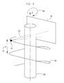
- Fig. 3 is a graphical representation of a helical scanning path performed by the system illustrated in Fig, 1 .
- Fig. 4A is a perspective view of a schematic representation of the inconsistency between measured x-rays according to the present invention.
- Fig. 4B is a top plan view of the schematic diagram of the inconsistency between measured x-rays illustrated in Fig. 4A .
- Fig. 4C is a side plan view of the schematic diagram of the inconsistency between measured x-rays illustrated in Fig. 4A .
- Fig. 5 is a schematic diagram of an image surface formed by measured x-rays at specified view angles along the helical scanning path according to the present invention.
- Fig. 6 is a pictorial view of a CT system for use with a non-invasive package inspection system.
- CT computed tomography
- a computed tomography (CT) imaging system 10 is shown as including a gantry 12 representative of a "third generation" CT scanner.
- Gantry 12 has an x-ray source 14 that projects a beam of x-rays 16 toward a detector assembly or collimator 18 on the opposite side of the gantry 12.
- detector assembly 18 is formed by a plurality of detectors 20 and data acquisition systems (DAS) 32.
- DAS data acquisition systems
- Each detector 20 produces an analog electrical signal that represents the intensity of an impinging x-ray beam and hence the attenuated beam as it passes through the patient 22.
- gantry 12 and the components mounted thereon rotate about a center of rotation 24.
- Control mechanism 26 includes an x-ray controller 28 that provides power and timing signals to an x-ray source 14 and a gantry motor controller 30 that controls the rotational speed and position of gantry 12.
- An image reconstructor 34 receives sampled and digitized x-ray data from DAS 32 and performs high speed reconstruction. The reconstructed image is applied as an input to a computer 36 which stores the image in a mass storage device 38.
- Computer 36 also receives commands and scanning parameters from an operator via console 40 that has some form of operator interface, such as a keyboard, mouse, voice activated controller, or any other suitable input apparatus.
- An associated display 42 allows the operator to observe the reconstructed image and other data from computer 36.
- the operator supplied commands and parameters are used by computer 36 to provide control signals and information to DAS 32, x-ray controller 28 and gantry motor controller 30.
- computer 36 operates a table motor controller 44 which controls a motorized table 46 to position patient 22 and gantry 12. Particularly, table 46 moves patients 22 through a gantry opening 48 of Fig. 1 in whole or in part.
- a helical or spiral scanning pattern 50 is shown according to one embodiment of the invention.
- the object 52 being scanned is translated along the z-axis while the source 14 and detector array 18 are rotated about the object 52 and a cone beam of x-rays 54 are emitted toward the object 52.
- a rebinning algorithm In order to reconstruct images from the projection data acquired during the helical CT scan, a rebinning algorithm is introduced.
- the goal of the rebinning algorithm is the formation of a plurality of two-dimensional sinograms from which a plurality of 2D images can be reconstructed.
- a significant factor in defining a rebinning algorithm is the choice of image surfaces for which the 2D sinograms will be estimated.
- each ray in the 2D sinogram is approximated by interpolating the measured cone beam data.
- all measured rays used for this purpose should lie within the image surface; however, with a helical scan path 50 this condition cannot be satisfied and the rebinning algorithms are only approximate.
- the rays used for rebinning should be selected as close as possible to the image surface to reconstruct, and the extent to which this can be done depends on the choice of the surface.
- the plurality of specified view angles are equally spaced along the helix, and the interval between the view angles are chosen based on the number of 2D reconstructions that can be performed in a desired time frame selected by an operator.
- a 2D sinogram is generated that covers all angles from 0 to ⁇ .
- the rays that are used to generate this sinogram come from the view angle range ⁇ n - ⁇ n + ⁇ .
- the rays selected for generating the sinogram are selected based on a minimum inconsistency between the rays. This inconsistency is determined by way of a pair of functions, ⁇ ( ⁇ , s) and w r ( ⁇ , s) that define a cone angle (i.e., the angle of a ray relative to the x-y plane) and redundancy weight, respectively. These functions are the same as those defined in Eqn A.
- k' is the index of the view that is conjugate to the one indexed by k
- M is the number of pixels in the xy plane within the field of view
- K is the number of view angles in the range - ⁇ to ⁇
- S is a function that gives the distance between a point and the origin in the s direction
- z is a function that gives the z position at which the surface of rays selected by the function ⁇ (at the given view angle) intersects the line parallel to the z axis which contains the point (x,y,0).
- Eta, ⁇ is a free parameter. If it is set to zero, the second expression, Eqn. 3, reduces to the first expression, Eqn. 2.
- ⁇ can be set to a non-zero value in recognition of the fact that when the object being imaged is smooth, a weighted average of two intersecting line integrals gives a good estimate of the line integral on another line that passes through the intersection of the first two.
- additional rays are included in the optimization. These additional rays are formed as a weighted average of each ray with its conjugate, wherein the weights used in the average are defined by the redundancy weight function. As ⁇ is increased, more emphasis is placed on these additional rays in the inconsistency minimization procedure.
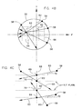
- K would likely be much higher (e.g., many hundreds), however, only the rays corresponding to four view angles are shown here for simplicity.
- a line 68 parallel to the z-axis is selected which passes through a point (x m , y m , 0).
- Intersection points 69 are identified along the line 68 at the x m , y m location at differing z values, as determined by the z value at which each of the four measured rays 60 passes through line 68. These intersection points are defined by a (x m , y m , z(x m , y m , k)) location for each of the four view angles 62 corresponding to values of k.
- K number of measured rays 60 pass through a single (x,y) image location, one for each view angle.
- each of the measured rays 60 passes through line 68 at the selected (x,y) image location at an angle relative to the x-y plane. That is, each ray 60 has a defined cone angle 70 at which it passes through line 68.
- the functions ⁇ and w r are chosen such that the rays 60 have cone angles 70 that will minimize the distance in the z direction at which the rays intersect line 68, thus minimizing the inconsistency among the rays they define.
- the minimization of the inconsistency functional can be accomplished through an iterative gradient descent method.
- the cone angle function could be set to zero everywhere and the redundancy weight could be set to 0.5 everywhere (Step A).
- a loop is then initiated in which a first inconsistency is calculated based on ⁇ and r w (Step B).
- the gradient (G1) of the inconsistency functional is computed with respect to each element of ⁇ (Step C).
- a second inconsistency is then calculated based on ⁇ ' and r w , where ⁇ ' is derived from G1, ⁇ , and a first step size parameter (Step D).
- the first inconsistency is then compared to the second inconsistency, and the smaller of the two is selected. If the second inconsistency is selected, ⁇ is replaced with ⁇ ' (Step E). Otherwise, the first step size parameter is reduced.
- Step F a gradient (G2) of the inconsistency functional with respect to r w is computed (Step F).
- a third inconsistency is then calculated based on ⁇ and r w ', where r w ' is derived from G2, r w , and a second step size parameter (Step G).
- the inconsistency selected in Step E is then compared to the third inconsistency, and the smaller of the two is selected (Step H). If the third inconsistency is selected, r w is replaced by r w ', otherwise, the second step size parameter is reduced.
- Step B thru Step G are repeated until a stopping criterion is met. This criterion can, for example, be based on number of iterations or on a measure of the step size parameters.
- constraints may be placed upon ⁇ based on the size of the detector array, such as for example,
- the pitch 72 i.e., the speed at which the helical scanning is performed as a function of z-axis translation and rotation of the x-ray source about the z-axis, as shown in Fig. 3
- the iterative gradient descent method set forth above will still yield an optimal set of functions ( ⁇ and r w ) for the geometry being studied.
- the gradient descent algorithm functions to minimize the separation in the z direction of the intersection points 69 along line 68 created by measured rays 60.
- Each of these measured rays 60 is attracted to each of the other rays.
- the attraction force is proportional to the separation in z, and the net force on any particular ray 60 from this (x,y) location will be oriented toward the average z location of all the rays. 1f this force is added to the forces acting on this ray from other image locations, (x m ,y m ), the result is the derivative of the inconsistency with respect to the cone angle 70 of that measured ray 60.
- This can be implemented in a structure similar to a forward projection.
- Equation A makes use of the symmetry of the helix such that it can be used in the formation of each sinogram at each of the plurality of view angles. That is, the functions ⁇ and r w are independent of the specified view angle, ⁇ n .
- a 2D reconstruction technique can be implemented to reconstruct an image from the sinogram.
- a direct Fourier method or 2D filtered backprojection (FBP) can be used to reconstruct a good estimate of an image for the surface at the specified view angle.
- Fig. 5 shows a portion of the helix 50 formed by the helical scanning pattern having measured rays 60 at two separate view angles 74, 76 where 2D sinograms are formed. A first set of rays 78 that are parallel to the xz plane are shown at the first view angle 74, and a second set of rays 80 that are parallel to the yz plane at the second view angle 76 are shown, the measured rays 60 intersecting the helix 50 as shown.
- the cone angle for each measured ray 60 is based on an optimized ray consistency that is a function of the inconsistency between the measured rays 60 as determined by ⁇ and w r .
- the set of rays 78, 80 at each of the specified view angles 74, 76 reflect a minimized inconsistency between measured rays 60 as determined by the selected cone angle for each measured ray 60 and are formed by the measured rays 60 to have a shape representative of the cone angles for each of the measured rays 60.
- an image surface 82 is determined by examining the location of first set of rays 78 and the location of second set of rays 80.
- This image surface will typically not be planar, but rather, will be a warped surface that is very consistent with a portion of the helix 50.
- image surface 82 mimics the helix scanning pattern and will often have a warped surface, as the image surface is determined based on its relationship to measured rays 60 that each have varying cone angles relative to one another. Again, due to symmetry, each image surface 82 that is formed at a specified view angle will be identical to other image surfaces except for a rotation and a translation. Consequently, these additional image surfaces can also be easily pre-computed.
- Each image surface 82 that is defined will thus form a two-dimensional image for each of the reconstructed sinograms.
- the two-dimensional images are comprised of a plurality of voxels on the respective image surfaces.
- the location of each of the plurality of voxels within a three-dimensional (3D) reconstruction cylinder is then determined to allow for reconstruction of a 3D image from the plurality of image surfaces, and the voxels thereon, that have been determined.
- the plurality of voxels from each of the image surfaces is interpolated in the z-direction onto a rectilinear grid to form an image thereon.
- This interpolation step is optional, but if it is not done, a weighting function would need to be applied to the final image if it is to be used to compute the total x-ray mass or the total volume of a selected region. It should also be recognized that without this interpolation of the image in the z-direction, the images will exhibit a geometric distortion.
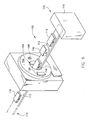
- a package/baggage inspection system 100 can incorporate a ray-consistency based reconstruction technique in reconstructing images of baggage scanned therein.
- Package/baggage inspection system 100 includes a rotatable gantry 102 having an opening 104 therein through which packages or pieces of baggage may pass.
- the rotatable gantry 102 houses a high frequency electromagnetic energy source 106 that emits a cone beam of rays as well as a detector assembly 108 having scintillator arrays comprised of scintillator cells.
- a conveyor system 110 is also provided and includes a conveyor belt 112 supported by structure 114 to automatically and continuously pass packages or baggage pieces 116 through opening 104 to be scanned.
- Objects 116 are fed through opening 104 by conveyor belt 112 and imaging data is then acquired, the imaging data corresponding to a helical scan pattern of cone beam data, as the high frequency electromagnetic energy source 106 and the detector assembly 108 rotate about the continuously moving conveyor belt 112 and baggage pieces 116.
- This helical pattern of cone beam data is then reconstructed in system 100 by way of the ray-consistency based reconstruction technique set forth in detail above to reconstruct images of baggage 116.
- the conveyor belt 112 also functions to remove the packages 116 from opening 104 in a controlled and continuous manner after scanning is completed. As a result, postal inspectors, baggage handlers, and other security personnel may non-invasively inspect the contents of packages 116 for explosives, knives, guns, contraband, etc.
- a technical contribution for the disclosed method and apparatus is that is provides for a computer implemented technique for reconstruction in computed tomography (CT) systems. More particularly, the disclosed method and apparatus provides for rebinning cone beam projection data into a series of two-dimensional sinograms based on an optimized ray consistency approach.
- CT computed tomography
- a CT imaging system includes a rotatable gantry having an opening to receive an object to be scanned, a high frequency electromagnetic energy projection source configured to project a cone beam of high frequency electromagnetic rays toward the object, and a detector array to detect the cone beam of high frequency electromagnetic rays and generate cone beam data therefrom.
- the CT imaging system also includes a computer, the computer being programmed to: receive the cone beam data from the detector array, specify a plurality of view angles, and select a plurality of measured rays for each of the plurality of specified view angles, the plurality of measured rays having a view angle approximate to the specified view angle as determined by an optimized ray consistency.
- the computer is also programmed to form a two-dimensional sinogram for each of the plurality of specified view angles based on the selected plurality of measured rays and define an image surface for each of the plurality of specified view angles based on the selected plurality of measured rays.
- a computer readable storage medium includes a computer program stored thereon representing a set of instructions, that when executed by a computer, causes the computer to acquire projection data from a cone beam of x-rays detected by a detector array, the cone beam projection data acquired for an imaging volume, and re-bin the cone beam projection data to parallel geometry cone data, wherein x-rays in the parallel geometry cone data are defined as a function of a cone angle, in-plane displacement relative to a rotation axis, and a view angle.
- the instructions further cause the computer to select x-rays from the parallel geometry cone data having a cone angle and redundancy weight that minimize an inconsistency between the x-rays, determine a plurality of image surfaces from the selected x-rays, and form a two-dimensional sinogram for each of the plurality of image surfaces.
- a method of image reconstruction of cone beam CT data includes the steps of receiving x-ray cone beam data in a helix pattern for a plurality of points along a longitudinal axis and specifying a plurality of view angles about the longitudinal axis about which to form two-dimensional sinograms.
- the method further includes the steps of selecting a plurality of x-rays from the cone beam data having a view angle in proximity to the specified view angle based on an optimized ray consistency between x-rays in the cone beam data, generating the two-dimensional sinogram from the selected plurality of x-rays, and associating a two-dimensional image surface with the sinogram the two-dimensional surface having a best fit with the selected plurality of x-rays.
Landscapes
- Health & Medical Sciences (AREA)
- Life Sciences & Earth Sciences (AREA)
- Engineering & Computer Science (AREA)
- Medical Informatics (AREA)
- Physics & Mathematics (AREA)
- Radiology & Medical Imaging (AREA)
- Surgery (AREA)
- Nuclear Medicine, Radiotherapy & Molecular Imaging (AREA)
- Optics & Photonics (AREA)
- Pathology (AREA)
- Biophysics (AREA)
- Biomedical Technology (AREA)
- Heart & Thoracic Surgery (AREA)
- Molecular Biology (AREA)
- High Energy & Nuclear Physics (AREA)
- Animal Behavior & Ethology (AREA)
- General Health & Medical Sciences (AREA)
- Public Health (AREA)
- Veterinary Medicine (AREA)
- General Physics & Mathematics (AREA)
- Theoretical Computer Science (AREA)
- Apparatus For Radiation Diagnosis (AREA)
Applications Claiming Priority (3)
| Application Number | Priority Date | Filing Date | Title |
|---|---|---|---|
| US84559306P | 2006-09-19 | 2006-09-19 | |
| US11/771,297 US7933375B2 (en) | 2006-09-19 | 2007-06-29 | Ray consistency based reconstruction of helical cone beam data |
| PCT/US2007/074273 WO2008036463A2 (en) | 2006-09-19 | 2007-07-25 | Ray consistency based reconstruction of helical cone beam data |
Publications (2)
| Publication Number | Publication Date |
|---|---|
| EP2067122A2 EP2067122A2 (en) | 2009-06-10 |
| EP2067122B1 true EP2067122B1 (en) | 2010-07-14 |
Family
ID=39179565
Family Applications (1)
| Application Number | Title | Priority Date | Filing Date |
|---|---|---|---|
| EP07853504A Active EP2067122B1 (en) | 2006-09-19 | 2007-07-25 | Ray consistency based reconstruction of helical cone beam data |
Country Status (6)
| Country | Link |
|---|---|
| US (1) | US7933375B2 (enExample) |
| EP (1) | EP2067122B1 (enExample) |
| JP (1) | JP2010504160A (enExample) |
| AT (1) | ATE474294T1 (enExample) |
| DE (1) | DE602007007793D1 (enExample) |
| WO (1) | WO2008036463A2 (enExample) |
Families Citing this family (8)
| Publication number | Priority date | Publication date | Assignee | Title |
|---|---|---|---|---|
| US8804899B2 (en) | 2003-04-25 | 2014-08-12 | Rapiscan Systems, Inc. | Imaging, data acquisition, data transmission, and data distribution methods and systems for high data rate tomographic X-ray scanners |
| US8204173B2 (en) * | 2003-04-25 | 2012-06-19 | Rapiscan Systems, Inc. | System and method for image reconstruction by using multi-sheet surface rebinning |
| DE102007024409A1 (de) * | 2007-05-25 | 2008-11-27 | Siemens Ag | Verfahren und Röntgen-CT-System zur Erzeugung computertomographischer Darstellungen |
| US8027427B2 (en) * | 2009-08-31 | 2011-09-27 | Morpho Detection, Inc. | Systems and method for scanning a continuous stream of objects |
| US8254656B2 (en) | 2009-10-13 | 2012-08-28 | Morpho Detection, Inc. | Methods and system for selective resolution improvement in computed tomography |
| US20120162216A1 (en) * | 2010-12-22 | 2012-06-28 | Electronics And Telecommunications Research Institute | Cylindrical three-dimensional image display apparatus and method |
| BE1019941A3 (nl) * | 2012-06-05 | 2013-02-05 | Tait Technologies Bvba | Inrichting voor de weergave van driedimensionale beelden, systeem voor de creatie van driedimensionale beelden, en werkwijze voor de creatie van driedimensionale beelden. |
| US10288762B2 (en) | 2016-06-21 | 2019-05-14 | Morpho Detection, Llc | Systems and methods for detecting luggage in an imaging system |
Family Cites Families (11)
| Publication number | Priority date | Publication date | Assignee | Title |
|---|---|---|---|---|
| JPH0471540A (ja) * | 1990-07-12 | 1992-03-06 | Toshiba Corp | X線ct装置 |
| JP3313397B2 (ja) * | 1992-05-21 | 2002-08-12 | 株式会社東芝 | X線ct装置 |
| US5802134A (en) | 1997-04-09 | 1998-09-01 | Analogic Corporation | Nutating slice CT image reconstruction apparatus and method |
| US6343108B1 (en) * | 1999-06-18 | 2002-01-29 | Philips Medical Systems (Cleveland), Inc. | Cone beam scanner using oblique surface reconstructions |
| AU2002360580A1 (en) * | 2001-12-14 | 2003-06-30 | Wisconsin Alumni Research Foundation | Virtual spherical anode computed tomography |
| US6529575B1 (en) * | 2002-04-29 | 2003-03-04 | Ge Medical Systems Global Technology Company, Llc | Adaptive projection filtering scheme for noise reduction |
| JP4309621B2 (ja) * | 2002-06-26 | 2009-08-05 | 株式会社東芝 | X線コンピュータ断層撮影装置 |
| US7292717B2 (en) | 2003-06-18 | 2007-11-06 | Koninklijke Philips Electronics N.V. | Computer tomography method using redundant measured values |
| JP2005143947A (ja) * | 2003-11-18 | 2005-06-09 | Hitachi Medical Corp | X線ct装置 |
| US20060020200A1 (en) * | 2004-07-08 | 2006-01-26 | Medow Joshua E | Artifact-free CT angiogram |
| US7050528B2 (en) * | 2004-09-30 | 2006-05-23 | Wisconsin Alumni Research Foundation | Correction of CT images for truncated or incomplete projections |
-
2007
- 2007-06-29 US US11/771,297 patent/US7933375B2/en active Active
- 2007-07-25 JP JP2009529286A patent/JP2010504160A/ja active Pending
- 2007-07-25 AT AT07853504T patent/ATE474294T1/de not_active IP Right Cessation
- 2007-07-25 DE DE602007007793T patent/DE602007007793D1/de active Active
- 2007-07-25 WO PCT/US2007/074273 patent/WO2008036463A2/en not_active Ceased
- 2007-07-25 EP EP07853504A patent/EP2067122B1/en active Active
Also Published As
| Publication number | Publication date |
|---|---|
| US7933375B2 (en) | 2011-04-26 |
| ATE474294T1 (de) | 2010-07-15 |
| EP2067122A2 (en) | 2009-06-10 |
| DE602007007793D1 (de) | 2010-08-26 |
| US20080192886A1 (en) | 2008-08-14 |
| JP2010504160A (ja) | 2010-02-12 |
| WO2008036463A2 (en) | 2008-03-27 |
| WO2008036463A3 (en) | 2008-05-22 |
Similar Documents
| Publication | Publication Date | Title |
|---|---|---|
| US6907102B1 (en) | Iterative reconstruction methods for multi-slice computed tomography | |
| US6768782B1 (en) | Iterative method for region-of-interest reconstruction | |
| EP2067122B1 (en) | Ray consistency based reconstruction of helical cone beam data | |
| US7865006B2 (en) | Methods and apparatus for artifact reduction | |
| US5430783A (en) | Reconstruction method for helical scanning computed tomography apparatus with multi-row detector array employing overlapping beams | |
| JP4360817B2 (ja) | 放射線断層撮影装置 | |
| JP4553894B2 (ja) | 正確な再構成を伴うヘリカルコーンビームコンピュータトモグラフィのためのシステム及び方法 | |
| US8995735B2 (en) | System and method for wide cone helical image reconstruction using blending of two reconstructions | |
| JPH0661327B2 (ja) | 断層撮影像作成方法および装置 | |
| JPH08509408A (ja) | 円すい状ビームデータからの画像の再構成 | |
| JP2000107167A (ja) | 円錐状放射線ビ―ムを使用するコンピュ―タ断層撮影方法 | |
| JPH0919425A (ja) | X線コンピュータ断層撮影装置 | |
| CN100592340C (zh) | 运动假影补偿 | |
| IL96320A (en) | A method of local scanning with a fan beam using rebinding | |
| WO2006058124A1 (en) | Fan-beam and cone-beam image reconstruction using filtered backprojection of differentiated projection data | |
| NL1028225C2 (nl) | Werkwijze en inrichting voor artefactreductie in met een kegelbundel werkende CT-beeldreconstructie. | |
| US6339632B1 (en) | Multi slice single filtering helical weighting method and apparatus to use the same | |
| US20060020200A1 (en) | Artifact-free CT angiogram | |
| US7215734B2 (en) | Method and system for three-dimensional reconstruction of images | |
| JP3290726B2 (ja) | 透過型三次元断層撮影装置 | |
| US20050100127A1 (en) | Methods and apparatus for image reconstruction in distributed x-ray source CT systems | |
| US6885764B2 (en) | High Speed Z-smoothing method and apparatus for CT imaging system | |
| US6522714B1 (en) | Row-wise full helical view weighting method and apparatus for CT scanners | |
| JP2009534079A (ja) | 複数の部分的な走査軌道を有するコーンビーム・コンピュータ断層撮影 | |
| US5546439A (en) | Systems, methods and apparatus for incrementally reconstructing overlapped images in a CT system implementing a helical scan |
Legal Events
| Date | Code | Title | Description |
|---|---|---|---|
| PUAI | Public reference made under article 153(3) epc to a published international application that has entered the european phase |
Free format text: ORIGINAL CODE: 0009012 |
|
| 17P | Request for examination filed |
Effective date: 20090420 |
|
| AK | Designated contracting states |
Kind code of ref document: A2 Designated state(s): AT BE BG CH CY CZ DE DK EE ES FI FR GB GR HU IE IS IT LI LT LU LV MC MT NL PL PT RO SE SI SK TR |
|
| AX | Request for extension of the european patent |
Extension state: AL BA HR MK RS |
|
| GRAP | Despatch of communication of intention to grant a patent |
Free format text: ORIGINAL CODE: EPIDOSNIGR1 |
|
| GRAJ | Information related to disapproval of communication of intention to grant by the applicant or resumption of examination proceedings by the epo deleted |
Free format text: ORIGINAL CODE: EPIDOSDIGR1 |
|
| GRAP | Despatch of communication of intention to grant a patent |
Free format text: ORIGINAL CODE: EPIDOSNIGR1 |
|
| DAX | Request for extension of the european patent (deleted) | ||
| GRAS | Grant fee paid |
Free format text: ORIGINAL CODE: EPIDOSNIGR3 |
|
| GRAA | (expected) grant |
Free format text: ORIGINAL CODE: 0009210 |
|
| RAP1 | Party data changed (applicant data changed or rights of an application transferred) |
Owner name: MORPHO DETECTION, INC. |
|
| AK | Designated contracting states |
Kind code of ref document: B1 Designated state(s): AT BE BG CH CY CZ DE DK EE ES FI FR GB GR HU IE IS IT LI LT LU LV MC MT NL PL PT RO SE SI SK TR |
|
| REG | Reference to a national code |
Ref country code: GB Ref legal event code: FG4D |
|
| REG | Reference to a national code |
Ref country code: CH Ref legal event code: EP |
|
| REG | Reference to a national code |
Ref country code: IE Ref legal event code: FG4D |
|
| REF | Corresponds to: |
Ref document number: 602007007793 Country of ref document: DE Date of ref document: 20100826 Kind code of ref document: P |
|
| REG | Reference to a national code |
Ref country code: NL Ref legal event code: T3 |
|
| PGFP | Annual fee paid to national office [announced via postgrant information from national office to epo] |
Ref country code: FR Payment date: 20100805 Year of fee payment: 4 |
|
| LTIE | Lt: invalidation of european patent or patent extension |
Effective date: 20100714 |
|
| PG25 | Lapsed in a contracting state [announced via postgrant information from national office to epo] |
Ref country code: AT Free format text: LAPSE BECAUSE OF FAILURE TO SUBMIT A TRANSLATION OF THE DESCRIPTION OR TO PAY THE FEE WITHIN THE PRESCRIBED TIME-LIMIT Effective date: 20100714 Ref country code: FI Free format text: LAPSE BECAUSE OF FAILURE TO SUBMIT A TRANSLATION OF THE DESCRIPTION OR TO PAY THE FEE WITHIN THE PRESCRIBED TIME-LIMIT Effective date: 20100714 Ref country code: LT Free format text: LAPSE BECAUSE OF FAILURE TO SUBMIT A TRANSLATION OF THE DESCRIPTION OR TO PAY THE FEE WITHIN THE PRESCRIBED TIME-LIMIT Effective date: 20100714 |
|
| PG25 | Lapsed in a contracting state [announced via postgrant information from national office to epo] |
Ref country code: IS Free format text: LAPSE BECAUSE OF FAILURE TO SUBMIT A TRANSLATION OF THE DESCRIPTION OR TO PAY THE FEE WITHIN THE PRESCRIBED TIME-LIMIT Effective date: 20101114 Ref country code: PL Free format text: LAPSE BECAUSE OF FAILURE TO SUBMIT A TRANSLATION OF THE DESCRIPTION OR TO PAY THE FEE WITHIN THE PRESCRIBED TIME-LIMIT Effective date: 20100714 Ref country code: PT Free format text: LAPSE BECAUSE OF FAILURE TO SUBMIT A TRANSLATION OF THE DESCRIPTION OR TO PAY THE FEE WITHIN THE PRESCRIBED TIME-LIMIT Effective date: 20101115 Ref country code: SI Free format text: LAPSE BECAUSE OF FAILURE TO SUBMIT A TRANSLATION OF THE DESCRIPTION OR TO PAY THE FEE WITHIN THE PRESCRIBED TIME-LIMIT Effective date: 20100714 Ref country code: MC Free format text: LAPSE BECAUSE OF NON-PAYMENT OF DUE FEES Effective date: 20100731 Ref country code: BG Free format text: LAPSE BECAUSE OF FAILURE TO SUBMIT A TRANSLATION OF THE DESCRIPTION OR TO PAY THE FEE WITHIN THE PRESCRIBED TIME-LIMIT Effective date: 20101014 Ref country code: CY Free format text: LAPSE BECAUSE OF FAILURE TO SUBMIT A TRANSLATION OF THE DESCRIPTION OR TO PAY THE FEE WITHIN THE PRESCRIBED TIME-LIMIT Effective date: 20100714 |
|
| PG25 | Lapsed in a contracting state [announced via postgrant information from national office to epo] |
Ref country code: SE Free format text: LAPSE BECAUSE OF FAILURE TO SUBMIT A TRANSLATION OF THE DESCRIPTION OR TO PAY THE FEE WITHIN THE PRESCRIBED TIME-LIMIT Effective date: 20100714 Ref country code: GR Free format text: LAPSE BECAUSE OF FAILURE TO SUBMIT A TRANSLATION OF THE DESCRIPTION OR TO PAY THE FEE WITHIN THE PRESCRIBED TIME-LIMIT Effective date: 20101015 Ref country code: LV Free format text: LAPSE BECAUSE OF FAILURE TO SUBMIT A TRANSLATION OF THE DESCRIPTION OR TO PAY THE FEE WITHIN THE PRESCRIBED TIME-LIMIT Effective date: 20100714 Ref country code: BE Free format text: LAPSE BECAUSE OF FAILURE TO SUBMIT A TRANSLATION OF THE DESCRIPTION OR TO PAY THE FEE WITHIN THE PRESCRIBED TIME-LIMIT Effective date: 20100714 |
|
| PG25 | Lapsed in a contracting state [announced via postgrant information from national office to epo] |
Ref country code: DK Free format text: LAPSE BECAUSE OF FAILURE TO SUBMIT A TRANSLATION OF THE DESCRIPTION OR TO PAY THE FEE WITHIN THE PRESCRIBED TIME-LIMIT Effective date: 20100714 |
|
| PLBE | No opposition filed within time limit |
Free format text: ORIGINAL CODE: 0009261 |
|
| STAA | Information on the status of an ep patent application or granted ep patent |
Free format text: STATUS: NO OPPOSITION FILED WITHIN TIME LIMIT |
|
| PG25 | Lapsed in a contracting state [announced via postgrant information from national office to epo] |
Ref country code: CZ Free format text: LAPSE BECAUSE OF FAILURE TO SUBMIT A TRANSLATION OF THE DESCRIPTION OR TO PAY THE FEE WITHIN THE PRESCRIBED TIME-LIMIT Effective date: 20100714 Ref country code: IT Free format text: LAPSE BECAUSE OF FAILURE TO SUBMIT A TRANSLATION OF THE DESCRIPTION OR TO PAY THE FEE WITHIN THE PRESCRIBED TIME-LIMIT Effective date: 20100714 Ref country code: EE Free format text: LAPSE BECAUSE OF FAILURE TO SUBMIT A TRANSLATION OF THE DESCRIPTION OR TO PAY THE FEE WITHIN THE PRESCRIBED TIME-LIMIT Effective date: 20100714 Ref country code: RO Free format text: LAPSE BECAUSE OF FAILURE TO SUBMIT A TRANSLATION OF THE DESCRIPTION OR TO PAY THE FEE WITHIN THE PRESCRIBED TIME-LIMIT Effective date: 20100714 Ref country code: SK Free format text: LAPSE BECAUSE OF FAILURE TO SUBMIT A TRANSLATION OF THE DESCRIPTION OR TO PAY THE FEE WITHIN THE PRESCRIBED TIME-LIMIT Effective date: 20100714 |
|
| 26N | No opposition filed |
Effective date: 20110415 |
|
| PG25 | Lapsed in a contracting state [announced via postgrant information from national office to epo] |
Ref country code: ES Free format text: LAPSE BECAUSE OF FAILURE TO SUBMIT A TRANSLATION OF THE DESCRIPTION OR TO PAY THE FEE WITHIN THE PRESCRIBED TIME-LIMIT Effective date: 20101025 |
|
| REG | Reference to a national code |
Ref country code: DE Ref legal event code: R097 Ref document number: 602007007793 Country of ref document: DE Effective date: 20110415 |
|
| PG25 | Lapsed in a contracting state [announced via postgrant information from national office to epo] |
Ref country code: IE Free format text: LAPSE BECAUSE OF NON-PAYMENT OF DUE FEES Effective date: 20100725 |
|
| PG25 | Lapsed in a contracting state [announced via postgrant information from national office to epo] |
Ref country code: MT Free format text: LAPSE BECAUSE OF FAILURE TO SUBMIT A TRANSLATION OF THE DESCRIPTION OR TO PAY THE FEE WITHIN THE PRESCRIBED TIME-LIMIT Effective date: 20100714 |
|
| REG | Reference to a national code |
Ref country code: CH Ref legal event code: PL |
|
| REG | Reference to a national code |
Ref country code: FR Ref legal event code: ST Effective date: 20120330 |
|
| PG25 | Lapsed in a contracting state [announced via postgrant information from national office to epo] |
Ref country code: FR Free format text: LAPSE BECAUSE OF NON-PAYMENT OF DUE FEES Effective date: 20110801 Ref country code: LI Free format text: LAPSE BECAUSE OF NON-PAYMENT OF DUE FEES Effective date: 20110731 Ref country code: CH Free format text: LAPSE BECAUSE OF NON-PAYMENT OF DUE FEES Effective date: 20110731 |
|
| PG25 | Lapsed in a contracting state [announced via postgrant information from national office to epo] |
Ref country code: HU Free format text: LAPSE BECAUSE OF FAILURE TO SUBMIT A TRANSLATION OF THE DESCRIPTION OR TO PAY THE FEE WITHIN THE PRESCRIBED TIME-LIMIT Effective date: 20110115 Ref country code: LU Free format text: LAPSE BECAUSE OF NON-PAYMENT OF DUE FEES Effective date: 20100725 |
|
| PG25 | Lapsed in a contracting state [announced via postgrant information from national office to epo] |
Ref country code: TR Free format text: LAPSE BECAUSE OF FAILURE TO SUBMIT A TRANSLATION OF THE DESCRIPTION OR TO PAY THE FEE WITHIN THE PRESCRIBED TIME-LIMIT Effective date: 20100714 |
|
| PGFP | Annual fee paid to national office [announced via postgrant information from national office to epo] |
Ref country code: NL Payment date: 20130726 Year of fee payment: 7 |
|
| REG | Reference to a national code |
Ref country code: DE Ref legal event code: R082 Ref document number: 602007007793 Country of ref document: DE Representative=s name: MUELLER FOTTNER STEINECKE RECHTSANWAELTE PATEN, DE |
|
| REG | Reference to a national code |
Ref country code: DE Ref legal event code: R081 Ref document number: 602007007793 Country of ref document: DE Owner name: MORPHO DETECTION, LLC (N.D.GES.D.STAATES DELAW, US Free format text: FORMER OWNER: MORPHO DETECTION INC., NEWARK, CALIF., US Effective date: 20140908 Ref country code: DE Ref legal event code: R082 Ref document number: 602007007793 Country of ref document: DE Representative=s name: MUELLER FOTTNER STEINECKE RECHTSANWALTS- UND P, DE Effective date: 20140908 Ref country code: DE Ref legal event code: R082 Ref document number: 602007007793 Country of ref document: DE Representative=s name: MUELLER FOTTNER STEINECKE RECHTSANWAELTE PATEN, DE Effective date: 20140908 |
|
| REG | Reference to a national code |
Ref country code: NL Ref legal event code: V1 Effective date: 20150201 |
|
| PG25 | Lapsed in a contracting state [announced via postgrant information from national office to epo] |
Ref country code: NL Free format text: LAPSE BECAUSE OF NON-PAYMENT OF DUE FEES Effective date: 20150201 |
|
| REG | Reference to a national code |
Ref country code: DE Ref legal event code: R082 Ref document number: 602007007793 Country of ref document: DE Representative=s name: WITTHOFF JAEKEL STEINECKE PATENTANWAELTE PARTG, DE |
|
| P01 | Opt-out of the competence of the unified patent court (upc) registered |
Effective date: 20230528 |
|
| PGFP | Annual fee paid to national office [announced via postgrant information from national office to epo] |
Ref country code: GB Payment date: 20250605 Year of fee payment: 19 |
|
| PGFP | Annual fee paid to national office [announced via postgrant information from national office to epo] |
Ref country code: DE Payment date: 20250604 Year of fee payment: 19 |