EP2066203B1 - Küchenmaschine mit entriegelungsknopf am deckel - Google Patents
Küchenmaschine mit entriegelungsknopf am deckel Download PDFInfo
- Publication number
- EP2066203B1 EP2066203B1 EP07802885A EP07802885A EP2066203B1 EP 2066203 B1 EP2066203 B1 EP 2066203B1 EP 07802885 A EP07802885 A EP 07802885A EP 07802885 A EP07802885 A EP 07802885A EP 2066203 B1 EP2066203 B1 EP 2066203B1
- Authority
- EP
- European Patent Office
- Prior art keywords
- lid
- food processor
- setting
- coupling point
- order
- Prior art date
- Legal status (The legal status is an assumption and is not a legal conclusion. Google has not performed a legal analysis and makes no representation as to the accuracy of the status listed.)
- Not-in-force
Links
- 230000008878 coupling Effects 0.000 claims abstract description 31
- 238000010168 coupling process Methods 0.000 claims abstract description 31
- 238000005859 coupling reaction Methods 0.000 claims abstract description 31
- 238000004873 anchoring Methods 0.000 claims description 28
- 230000009979 protective mechanism Effects 0.000 claims description 4
- 210000002105 tongue Anatomy 0.000 description 8
- 238000001514 detection method Methods 0.000 description 4
- 230000004224 protection Effects 0.000 description 3
- 230000000994 depressogenic effect Effects 0.000 description 2
- 230000001419 dependent effect Effects 0.000 description 1
- 238000011161 development Methods 0.000 description 1
- 230000018109 developmental process Effects 0.000 description 1
- 238000007373 indentation Methods 0.000 description 1
- 238000003754 machining Methods 0.000 description 1
- 230000001681 protective effect Effects 0.000 description 1
- 230000000284 resting effect Effects 0.000 description 1
Images

Classifications
-
- A—HUMAN NECESSITIES
- A47—FURNITURE; DOMESTIC ARTICLES OR APPLIANCES; COFFEE MILLS; SPICE MILLS; SUCTION CLEANERS IN GENERAL
- A47J—KITCHEN EQUIPMENT; COFFEE MILLS; SPICE MILLS; APPARATUS FOR MAKING BEVERAGES
- A47J43/00—Implements for preparing or holding food, not provided for in other groups of this subclass
- A47J43/04—Machines for domestic use not covered elsewhere, e.g. for grinding, mixing, stirring, kneading, emulsifying, whipping or beating foodstuffs, e.g. power-driven
- A47J43/046—Machines for domestic use not covered elsewhere, e.g. for grinding, mixing, stirring, kneading, emulsifying, whipping or beating foodstuffs, e.g. power-driven with tools driven from the bottom side
-
- A—HUMAN NECESSITIES
- A47—FURNITURE; DOMESTIC ARTICLES OR APPLIANCES; COFFEE MILLS; SPICE MILLS; SUCTION CLEANERS IN GENERAL
- A47J—KITCHEN EQUIPMENT; COFFEE MILLS; SPICE MILLS; APPARATUS FOR MAKING BEVERAGES
- A47J43/00—Implements for preparing or holding food, not provided for in other groups of this subclass
- A47J43/04—Machines for domestic use not covered elsewhere, e.g. for grinding, mixing, stirring, kneading, emulsifying, whipping or beating foodstuffs, e.g. power-driven
- A47J43/07—Parts or details, e.g. mixing tools, whipping tools
- A47J43/075—Safety devices
- A47J43/0761—Safety devices for machines with tools driven from the lower side
Definitions
- the present invention relates to a food processor with a lid and a locking device according to the preamble of claim 1.
- EP 1535558 A1 is a kitchen machine with two coupling points for processing equipment known, one of which is covered with a lid.
- the cover is pivotally mounted about a hinge axis on the housing so that it can be pivoted from a closed position in which it covers the coupling point in an open position in which the processing unit can be placed on the coupling point.
- the lid has on its underside a tab with an anchoring element which engages with the lid closed in a recess in the housing of the food processor. There, it is held in place by a retaining member in the housing to hold the lid in its closed position.
- the retaining element is connected to a arranged on the outside of the housing of the food processor unlocking button. By pressing the release button, the anchoring element is released against the force of an elastic return element of the retaining element and the cover pivots driven by another elastic return element in the vicinity of the hinge axis automatically in its open position.
- the WO 95/20903 A also discloses a food processor with a coupling point for coupling a machining tool.
- the dome of the WO 95/20903 A is covered by a pivoting arm, which has a control knob in its adjacent to the coupling point area.
- the swivel arm is secured by means of a locking device on the main body of the food processor.
- the locking device is as intuitive as possible to handle.
- the invention teaches a food processor with a lid and a locking device with the features of claim 1.
- the lid according to the invention comprises an anchoring element, and the housing has a retaining element which can cooperate with the anchoring element to lock the lid in the closed position.
- the anchoring and retaining elements preferably cooperate in the manner of a snap closure, wherein for locking in each case a first latching element of an anchoring element and a second latching element of a retaining element engage each other.
- the first latching element preferably has an upper edge and the second latching element has a lower edge which, viewed in the closing direction, can engage under the upper edge of the first latching element in order to lock the cover in the closed position.
- the anchoring element is preferably formed as a tongue which extends from the underside of the lid in the direction of the coupling point.
- the tongue is preferably elastically bendable perpendicular to its extension direction.
- the second latching element is preferably a projection on the end facing away from the lid of the tongue. Particularly preferably, two tongues are provided, wherein the two projections face each other.
- the retaining element is preferably a ring, more preferably a circular ring at the coupling point and the first locking element is preferably formed from the upper edge of an opening in the wall of the ring.
- the ring is designed like a hollow truncated cone, with the bevel radius increasing toward the lower edge.
- the unlocking button has an unlocking section, which preferably cooperates with the anchoring element in such a way that, in the release position, it releases the anchoring element from the retaining element.
- it bends the anchoring element particularly preferably against its bias away from the retaining element, so that the two locking elements no longer engage with each other.
- the unlocking portion is preferably formed as a tongue which extends from the underside of the release button in the direction of the coupling point.
- a preferred unlocking section is arranged at least in the release position between anchoring element and retaining element in order to release the anchoring element from the retaining element. Upon actuation of the release button, the unlocking section slides between anchoring element and retaining element.
- the unlocking section comprises two tongues, which in each case between an anchoring element and the.
- the preferred unlocking button on an operating portion which is actuated by the accessible with the lid closed outside of the lid.
- the preferred unlocking button is arranged in a preferably central opening of the lid.
- the actuating portion preferably closes in the resting state of the unlocking button flush with the outside of the lid.
- To unlock the unlocking can be pressed by a user preferably down towards coupling point.
- the unlocking section attached to the actuating section advantageously slides downwards between the anchoring element and the retaining element in order to separate them from one another.
- a preferred food processor has a first return device which biases the lid in the open position.
- the first return device is preferably housed in a hinge, with which the lid is pivotally mounted on the housing of the food processor. It particularly preferably comprises a helical spring.
- the return device preferably comprises a braking device, e.g. a viscous damper to dampen the opening movement.
- the locking button preferably has a second restoring device, which biases the unlocking button in its rest position.
- the restoring device is preferably a helical spring.
- the restoring force of the first and the second restoring device are preferably matched to one another such that the second restoring device can lift the cover in the release position of the unlocking button so far that the upper edge of the first locking element lies in the opening direction over the lower edge of the second locking element.
- the restoring force of the first restoring device with the lid closed is greater than the restoring force of the second restoring device, when the unlock button is in its unlocked position.
- a shaft is preferably arranged to drive a tool of the processing device rotating.
- the shaft is preferably driven by a motor, particularly preferably an electric motor.
- a preferred food processor is also provided with a protective mechanism to avoid that the shaft is actuated when the coupling point is not covered by a processing device or the lid.
- the protection mechanism preferably has a detection device in order to detect the presence or absence of the processing device or of the cover and, depending on this, to close or interrupt the power supply to the motor.
- a preferred lid is provided with a projection which, when the lid is closed, actuates a detection device of the protective mechanism to indicate that the coupling point is covered.
- the food processor 1 shown in the figures has a housing 2 with a first coupling point 3 for a first processing device and a second coupling point 4 for a second processing device.
- the first Ankupplungsstelle 3 can be covered with a cover 5, which on the housing 2 between a closed ( Fig. 1 ) and an open ( Fig. 2 ) Position is pivotally mounted.
- a locking device By means of a locking device, the lid 5 can be locked in the closed position.
- a release button 6 the lock can be released, so that the lid 5 can be pivoted to the open position.
- the locking device comprises two tongue-like anchoring elements 7, 8, which project from the underside of the lid 5, and their mutually facing projections 9, 10, which can engage in corresponding openings 11, 12 of an annular retaining element at the first coupling point 3, to the cover fifth releasably fixed to the housing 2 in its closed position.
- the food processor also has a first return device with a first coil spring 16, which biases the lid 5 in its open position.
- a second coil spring 17 biases the locking knob 6 in its rest position.
- the restoring force of the first coil spring 16 with the lid closed is greater than the restoring force of the second coil spring with the release button 6 depressed, so that, after the anchoring elements 7, 8 have detached from the retaining element 13, the cover 5 raises so far with the release button 6 still depressed that the projections 9, 10 are lifted over the openings 11, 12. This prevents the locking mechanism from locking again when the release button is released. Instead, the cover 5 can now be driven by the first return device 16 open.
- the first return device 16 also includes a viscous damper 18 to brake the opening movement.
- the annular retaining element surrounds an opening in the housing 2 of the food processor, from which a shaft (not shown) for driving a tool of a processing device which can be placed on the coupling point, e.g. a jar, accessible from outside.
- the tool may e.g. be a whisk, a dough hook or a knife.
- the shaft is in turn driven by a motor which is located in the housing part below the coupling point 3. So that a user can not injure himself on the rotating shaft or on a tool attached to it, if no processing device is placed on the coupling point 3 and also the cover 5 is not in its closed position, the food processor has a protective device. This interrupts the power supply to the engine in the absence of processing equipment and lid 5 is not closed.
- the protection device In order to indicate to the protection device that the cover 5 is in the closed position, it is provided with a projection 18 which cooperates with a detection device of the protection device.
- the projection 18 engages with the lid 5 closed in an opening in the housing 2, where it is detected by the detection device.
- the invention allows a simple way to upgrade a food processor with a locking device.
- the food processor according to the invention is intuitive to handle.
Landscapes
- Engineering & Computer Science (AREA)
- Mechanical Engineering (AREA)
- Food Science & Technology (AREA)
- Closures For Containers (AREA)
- Food-Manufacturing Devices (AREA)
- General Preparation And Processing Of Foods (AREA)
Description
- Die vorliegende Erfindung betrifft eine Küchenmaschine mit einem Deckel und einer Verriegelungseinrichtung gemäß dem Oberbegriff des Anspruchs 1.
- Aus der europäischen Offenlegungsschrift
EP 1535558 A1 ist eine Küchenmaschine mit zwei Kupplungsstellen für Bearbeitungsgeräte bekannt, von denen eine mit einem Deckel abdeckbar ist. Der Deckel ist um eine Gelenkachse schwenkbar am Gehäuse befestigt, sodass er von einer geschlossenen Stellung, in der er die Kupplungsstelle abdeckt, in eine offene Stellung geschwenkt werden kann, in der das Bearbeitungsgerät auf die Kupplungsstelle aufgesetzt werden kann. Der Deckel weist auf seiner Unterseite eine Lasche mit einem Verankerungselement auf, das bei geschlossenem Deckel in eine Einbuchtung in Gehäuse der Küchenmaschine eingreift. Dort wird sie von einem Rückhalteelement im Gehäuse festgehalten, um den Deckel in seiner geschlossenen Stellung zu halten. Das Rückhalteelement ist mit einem an der Außenseite des Gehäuses der Küchenmaschine angeordneten Entriegelungsknopf verbunden. Durch Betätigen des Entriegelungsknopfs wird das Verankerungselement gegen die Kraft eines elastischen Rückstellelements des Rückhalteelements freigegeben und der Deckel schwenkt angetrieben durch ein weiteres elastisches Rückstellelement in der Nähe der Gelenkachse selbsttätig in seine offene Stellung. - Die
WO 95/20903 A WO 95/20903 A - Es ist wünschenswert, eine Küchenmaschine in verschiedenen Modellvarianten anbieten zu können, wobei z.B. eine preiswertere Version mit einem einfachen aufsetzbaren Deckel und eine komfortablere Version mit einer Verriegelungsvorrichtung ausgestattet ist. Um Kosten zu sparen, ist es wünschenswert, dass die verschiedenen Modellvarianten möglichst weitgehend aus identischen Komponenten konstruiert sind.
- Außerdem kann es wünschenswert sein, dass die Verriegelungsvorrichtung möglichst intuitiv handhabbar ist.
- Zu Lösung der Aufgabe lehrt die Erfindung eine Küchenmaschine mit einem Deckel und einer Verriegelungseinrichtung mit den Merkmalen des Anspruchs 1.
- Dadurch, dass der Entriegelungsknopf am Deckel der Küchenmaschine angeordnet ist, kann erreicht werden, dass eine Küchenmaschine einfach durch Ersetzen des Deckels mit der Verrieglungseinrichtung aufrüstbar ist. Im Vergleich dazu müssen bei der bekannten Küchenmaschine für die Modellvarianten unterschiedliche Gehäuse bereitgestellt werden, weil dort der Entriegelungsknopf am Gehäuse der Küchenmaschine angeordnet ist.
- Außerdem kann mit der Erfindung eine besonders intuitive Handhabung erreicht werde, wenn man davon ausgeht, dass ein unvoreingenommener Benutzer zunächst am Deckel selbst nach einer Möglichkeit sucht, diesen zu entriegeln.
- Vorteilhafte Aus- und Weiterbildungen, welche einzeln oder in Kombination miteinander eingesetzt werden können, sind Gegenstand der abhängigen Ansprüche.
- Der Deckel weist erfindungsgemäß ein Verankerungselement auf, und das Gehäuse ein Rückhalteelement, das mit dem Verankerungselement zusammenwirken kann, um den Deckel in der geschlossenen Stellung zu verriegeln. Die Verankerungs- und Rückhalteelemente wirken vorzugsweise nach Art eines Schnappverschlusses zusammen, wobei zum Verriegeln jeweils ein erstes Rastelement eines Verankerungselements und ein zweites Rastelement eines Rückhalteelements ineinander greifen.
- Vorzugsweise weist das erste Rastelement eine Oberkante und das zweite Rastelement eine Unterkante auf, die in Verschlussrichtung gesehen unter die Oberkante des ersten Rastelements greifen kann, um den Deckel in der geschlossenen Stellung zu verriegeln. Das Verankerungselement ist vorzugsweise als Zunge ausgebildet, die sich von der Unterseite des Deckels in Richtung der Kupplungsstelle erstreckt. Die Zunge ist vorzugsweise senkrecht zur ihrer Erstreckungsrichtung elastisch verbiegbar. Das zweite Rastelement ist vorzugsweise ein Vorsprung am von Deckel wegweisenden Ende der Zunge. Besonders vorzugsweise sind zwei Zungen vorgesehen, wobei die beiden Vorsprünge zueinander weisen.
- Das Rückhalteelement ist vorzugsweise ein Ring, besonders vorzugsweise ein Kreisring an der Kupplungsstelle und das erste Rastelement wird vorzugsweise vom oberen Rand einer Öffnung in der Wand des Rings gebildet. Oberhalb der Öffnung ist der Ring hohlkegelstumpfartig ausgebildet, wobei der Kegelradius zur Unterkante hin zunimmt. So kann erreicht werden, dass beim Schießen des Deckels das zungenartige Verankerungselement elastisch gegen eine zum Rückhalteelement hin gerichtete Vorspannung nach außen verbogen wird, bevor es mit seinem Vorsprung unter die Oberkante der Öffnung einrasten kann. An Stelle der Öffnung kann auch eine einfache Einbuchtung auf der Außenseite des Rings vorgesehen sein.
- Der Entriegelungsknopf weist erfindungsgemäß einen Entriegelungsabschnitt auf, der mit dem Verankerungselement vorzugsweise derart zusammenwirkt, dass er in der Freigabestellung das Verankerungselement von dem Rückhalteelement löst. Dazu biegt er das Verankerungselement besonders vorzugsweise gegen seine Vorspannung vom Rückhalteelement weg, sodass die beiden Rastelemente nicht mehr ineinander greifen.
- Der Entriegelungsabschnitt ist vorzugsweise als Zunge ausgebildet, die sich von der Unterseite des Entriegelungsknopfs in Richtung der Kupplungsstelle erstreckt. Ein bevorzugter Entriegelungsabschnitt ist mindestens in der Freigabestellung zwischen Verankerungselement und Rückhalteelement angeordnet, um das Verankerungselement von dem Rückhalteelement zu lösen. Beim Betätigen des Entriegelungsknopfs schiebt sich der Entriegelungsabschnitt zwischen Verankerungselement und Rückhalteelement. Besonders vorzugsweise umfasst der Entriegelungsabschnitt zwei Zungen, die sich beim betätigen des Entriegelungsknopfs jeweils zwischen ein Verankerungselement und das Verriegelungselement schieben, um das Verankerungselement vom Rückhalteelement zu lösen.
- Außerdem weist der bevorzugte Entriegelungsknopf einen Betätigungsabschnitt auf, der von der bei geschlossenem Deckel zugänglichen Außenseite des Deckels betätigbar ist. Der bevorzugte Entriegelungsknopf ist in einer vorzugsweise zentralen Öffnung des Deckels angeordnet. Der Betätigungsabschnitt schließt im Ruhezustand des Entriegelungsknopfes vorzugsweise bündig mit der Außenseite des Deckels ab. Zum Entriegeln kann der Entriegelungsabschnitt von einem Benutzer vorzugsweise nach unten in Richtung Kupplungsstelle gedrückt werden. Dabei schieben sich vorteilhafterweise der am Betätigungsabschnitt angebrachte Entriegelungsabschnitt nach unten zwischen Verankerungselement und Rückhalteelement, um diese voneinander zu lösen.
- Eine bevorzugte Küchenmaschine weist eine erste Rückstelleinrichtung auf, die den Deckel in die geöffnete Stellung vorspannt. So kann erreicht werden, dass sich der Deckel nach dem Entriegeln selbstständig von der geschlossenen in die geöffnete Stellung bewegt. Die erste Rückstelleinrichtung ist vorzugsweise in einem Scharnier untergebracht, mit dem der Deckel am Gehäuse der Küchenmaschine schwenkbar angebracht ist. Sie umfasst besonders vorzugsweise eine Schraubenfeder. Außerdem umfasst die Rückstelleinrichtung vorzugsweise eine Bremseinrichtung, z.B. einen Visko-Dämpfer, um die Öffnungsbewegung zu dämpfen.
- Der Verriegelungsknopf weist vorzugsweise eine zweite Rückstelleinrichtung auf, die den Entriegelungsknopf in seine Ruhestellung vorspannt. So kann erreicht werden, dass der Entriegelungsknopf nach der Betätigung von der Entriegelungsstellung in seine Ruhestellung zurückkehrt. Die Rückstelleinrichtung ist vorzugsweise eine Schraubenfeder.
- Die Rückstellkraft der ersten und der zweiten Rückstelleinrichtung sind vorzugsweise so aufeinander abgestimmt, dass die zweite Rückstelleinrichtung den Deckel in der Freigabestellung des Entriegelungsknopfs soweit anheben kann, dass die Oberkante des ersten Rastelements in Öffnungsrichtung über der Unterkante des zweiten Rastelementes liegt. Besonders vorzugsweise ist die Rückstellkraft der ersten Rückstelleinrichtung bei geschlossenem Deckel größer als die Rückstellkraft der zweiten Rückstelleinrichtung, wenn der Entriegelungsknopf in seiner Entriegelungsstellung ist. Durch die Abstimmung der Rückstellkräfte kann sichergestellt werden, dass auch beim Entlasten des Entriegelungsknopfs die Rastelemente nicht mehr ineinander greifen können und sich der Deckel angetrieben durch die erste Rückstelleinrichtung öffnen kann.
- An der mit dem Deckel ausgestatteten Kupplungsstelle der Küchenmaschine ist vorzugsweise eine Welle angeordnet, um ein Werkzeug des Bearbeitungsgeräts rotierend anzutreiben. Die Welle wird vorzugsweise mit einem Motor, besonders vorzugsweise einem Elektromotor, angetrieben. Eine bevorzugte Küchenmaschine ist außerdem mit einem Schutzmechanismus ausgestattet, um zu vermeiden, dass die Welle betätigt wird, wenn die Kupplungsstelle nicht durch ein Bearbeitungsgerät oder den Deckel abgedeckt ist. Der Schutzmechanismus weist dazu vorzugsweise eine Erfassungseinrichtung auf, um die Anwesenheit oder Abwesenheit des Bearbeitungsgeräts oder des Deckels zu erfassen und abhängig davon die Stromzufuhr zum Motor zu schließen oder zu unterbrechen.
- Ein bevorzugter Deckel ist mit einem Vorsprung ausgestattet, der bei geschlossenem Deckel eine Erfassungseinrichtung des Schutzmechanismus betätigt, um diesem anzuzeigen, dass die Kupplungsstelle abgedeckt ist. Dadurch, dass mittels der Verriegelungseinrichtung der Deckel auf dem Gehäuse fixiert werden kann, kann vorteilhaft sichergestellt werden, dass der Vorsprung bei geschlossenem Deckel mit ausreichender Kraft betätigt ist.
- Die Erfindung wird im Folgenden anhand schematischer Zeichnungen an einem Ausführungsbeispiel mit weiteren Einzelheiten näher erläutert.
- Es zeigen:
- Fig. 1:
- Eine perspektivische Ansicht einer erfindungsgemäßen Küchenmaschine mit geschlossenem Deckel;
- Fig. 2:
- Eine perspektivische Ansicht einer erfindungsgemäßen Küchenmaschine mit offenem Deckel;
- Fig. 3:
- Eine Schnittansicht der Verriegelungseinrichtung einer erfindungsgemäßen Küchenmaschine;
- Fig. 4:
- Eine Schnittansicht der ersten Rückstelleinrichtung einer erfindungsgemäßen Küchenmaschine; und
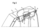
- Fig. 5:
- Eine perspektivische Aufrissansicht der Verriegelungseinrichtung und der Rückstelleinrichtung einer erfindungsgemäßen Küchenmaschine.
- Die in den Figuren dargestellte Küchenmaschine 1 weist eine Gehäuse 2 mit einer ersten Ankupplungsstelle 3 für ein erstes Bearbeitungsgerät und eine zweite Ankupplungsstelle 4 für ein zweites Bearbeitungsgerät auf. Die erste Ankupplungsstelle 3 ist mit einem Deckel 5 abdeckbar, der am Gehäuse 2 zwischen einer geschlossenen (
Fig. 1 ) und einer offenen (Fig. 2 ) Stellung schwenkbar befestigt ist. Mittels einer Verriegelungseinrichtung kann der Deckel 5 in der geschlossenen Stellung verriegelt werden. Mittels eines Entriegelungsknopfs 6 kann die Verriegelung gelöst werden, sodass der Deckel 5 in die offene Stellung geschwenkt werden kann. - Die Verriegelungseinrichtung umfasst zwei zungenartige Verankerungselemente 7, 8, die von der Unterseite des Deckels 5 abstehen, und deren zueinander weisende Vorsprünge 9, 10, die in entsprechende Öffnungen 11, 12 eines ringförmigen Rückhalteelements an der ersten Kupplungsstelle 3 eingreifen können, um den Deckel 5 in seiner geschlossenen Stellung lösbar am Gehäuse 2 zu fixieren.
- Von der Unterseite des Entriegelungsknopfs 6 stehen zwei Zungen 14, 15 ab, die zwischen dem Rückhalteelement 13 und den zungenartigen Verankerungselementen 7, 8 liegen. beim Niederdrücken des Entriegelungsknopfs spreizen die Zungen 14, 15 des Entriegelungsknopfs die Verankerungselemente 7, 8 voneinander weg, sodass sie sich von dem ringförmigen Rückhalteelement 13 lösen.
- Die Küchenmaschine weist außerdem eine erste Rückstelleinrichtung mit einer ersten Schraubenfeder 16 auf, die den Deckel 5 in seine geöffnete Stellung vorspannt. eine zweite Schraubenfeder 17 spannt den Verriegelungsknopf 6 in seine Ruhestellung vor. Die Rückstellkraft der ersten Schraubenfeder 16 bei geschlossenem Deckel ist größer als die Rückstellkraft der zweiten Schraubenfeder bei niedergedrücktem Entriegelungsknopf 6, sodass sich, nachdem sich die Verankerungselemente 7, 8 vom Rückhalteelement 13 gelöst haben, der Deckel 5 bei noch niedergedrücktem Entriegelungsknopf 6 soweit anhebt, dass die Vorsprünge 9, 10 über die Öffnungen 11, 12 gehoben werden. So wird verhindert, dass Die Verriegelung beim Loslassen des Entriegelungsknopfes wieder einrastet. Stattdessen kann sich der Deckel 5 nun angetrieben durch die erste Rückstelleinrichtung 16 öffnen. Die erste Rückstelleinrichtung 16 umfast außerdem eine Visko-Dämpfer 18, um die Öffnungsbewegung abzubremsen.
- Das ringförmige Rückhalteelement umgibt eine Öffnung im Gehäuse 2 der Küchenmaschine, aus der eine (nicht dargestellte) Welle zum Antrieb eines Werkzeugs eines auf die Kupplungsstelle aufsetzbaren Bearbeitungsgeräts, z.B. eines Mixbechers, von Außen zugänglich ist. Das Werkzeug kann z.B. ein Rührbesen, ein Knethaken oder ein Messer sein.
- Die Welle wird ihrerseits von eine Motor angetrieben, der sich in dem Gehäuseteil unterhalb der Kupplungsstelle 3 befindet. Damit ein Benutzer sich nicht an der rotierenden Welle oder an einem daran angebrachten Werkzeug verletzten kann, wenn auf die Kupplungsstelle 3 kein Bearbeitungsgerät aufgesetzt ist und auch der Deckel 5 nicht in seiner geschlossenen Stellung ist, weist die Küchenmaschine eine Schutzeinrichtung auf. Diese unterbricht die Stromzufuhr zum Motor bei fehlendem Bearbeitungsgerät und nicht geschlossenem Deckel 5.
- Um der Schutzeinrichtung anzuzeigen dass der Deckel 5 in der geschlossenen Stellung ist, ist dieser mit einem Vorsprung 18 ausgestattet, der mit einer Erfassungseinrichtung der Schutzeinrichtung zusammenwirkt. Dazu greift der Vorsprung 18, bei geschlossenem Deckel 5 in eine Öffnung im Gehäuse 2, wo er von der Erfassungseinrichtung detektiert wird.
- Die in der vorstehenden Beschreibung, den Ansprüchen und den Zeichnungen offenbarten Merkmale können sowohl einzeln als auch in beliebiger Kombination für die Verwirklichung der Erfindung in ihren verschiedenen Ausgestaltungen von Bedeutung sein.
- Die Erfindung erlaubt es auf einfache Weise, eine Küchenmaschine mit einer Verriegelungseinrichtung aufzurüsten. Außerdem ist die erfindungsgemäße Küchenmaschine intuitiv zu handhaben.
Claims (8)
- Küchenmaschine (1) mit einer Kupplungsstelle (3) zum Ankuppeln eines Bearbeitungsgeräts, einem Deckel (5), der von einer geschlossenen Stellung, in der er die Kupplungsstelle (3) abdeckt, in eine offene Stellung, in der die Kupplungsstelle (3) zum Ankuppeln des Bearbeitungsgeräts frei liegt, schwenkbar an einem Gehäuse (2) der Küchenmaschine (1) angebracht ist und einer Verriegelungseinrichtung, um den Deckel (5) in der geschlossenen Stellung zu verriegeln, mit einem Entriegelungsknopf (6), der durch Betätigung von einer Ruhestellung in eine Freigabestellung bewegbar ist, um die Verriegelung zu lösen, sodass der Deckel (5) in die offene Stellung geschwenkt werden kann, wobei der Entriegelungsknopf (6) am Deckel (5) angeordnet ist, wobei der Deckel (5) ein Verankerungselement (7, 8) aufweist und das Gehäuse (2) ein Rückhalteelement (13), das mit dem Verankerungselement (7, 8) zusammenwirken kann, um den Deckel (5) in der geschlossenen Stellung zu verriegeln, dadurch gekennzeichnet, dass der Entriegelungsknopf (6) einen Entriegelungsabschnitt (14, 15) aufweist, der mit dem Verankerungselement (7, 8) derart zusammenwirkt, dass er in der Freingabestellung das Verankerungselement (13) von dem Rückhalteelement (13) löst.
- Küchenmaschine (1) nach Anspruch 1, dadurch gekennzeichnet, dass das Verankerungselement (7, 8) ein erstes Rastelement (9, 10) mit einer Oberkante und das Rückhalteelement (13) ein zweites Rastelement (11, 12) mit einer Unterkante aufweist, wobei die Oberkante des ersten Rastelements (10, 11) in Verschlussrichtung gesehen unter die Unterkante des Rückhalteelements (13) greifen kann, um den Deckel (5) in der geschlossenen Stellung zu verriegeln.
- Küchenmaschine (1) nach Anspruch 1, dadurch gekennzeichnet, dass der Entriegelungsabschnitt (14, 15) mindestens in der Freigabestellung zwischen Verankerungselement (7, 8) und Rückhalteelement (13) angeordnet ist, um das Verankerungselement (7, 8) von dem Rückhalteelement (13) zu lösen.
- Küchenmaschine (1) nach einem der vorherigen Ansprüche, dadurch gekennzeichnet, dass sie eine erste Rückstelleinrichtung (16) aufweist, die den Deckel (5) in die geöffnete Stellung vorspannt.
- Küchenmaschine (1) nach einem der vorherigen Ansprüche, dadurch gekennzeichnet, dass der Entriegelungsknopf (6) eine zweite Rückstelleinrichtung (17) aufweist, die den Entriegelungsknopf (6) in seine Ruhestellung vorspannt.
- Küchenmaschine (1) nach einem der vorherigen Ansprüche, dadurch gekennzeichnet, dass die Rückstellkraft der ersten und der zweiten Rückstelleinrichtung (16, 17) so aufeinander abgestimmt sind, dass die zweite Rückstelleinrichtung (17) den Deckel (5) in der Freigabestellung des Entriegelungsknopfs (6) soweit anheben kann, dass die Oberkante des ersten Rastelements (9, 10) in Öffnungsrichtung über der Unterkante des zweiten Rastelementes (11, 12) liegt.
- Küchenmaschine (1) nach einem der vorherigen Ansprüche, dadurch gekennzeichnet, dass an der Kupplungsstelle (3) eine Welle angeordnet ist, um ein Werkzeug des Bearbeitungsgeräts rotierend anzutreiben, und die Küchenmaschine (1) mit einem Schutzmechanismus ausgestattet ist, um zu vermeiden, dass die Welle betätigt wird, wenn die Kupplungsstelle (3) nicht durch ein Bearbeitungsgerät oder den Deckel (5) abgedeckt ist.
- Küchenmaschine (1) nach Anspruch 7, dadurch gekennzeichnet, dass der Deckel (5) mit einem Vorsprung (18) ausgestattet ist, der bei geschlossenem Deckel (5) eine Erfassungseinrichtung des Schutzmechanismus betätigt, um diesem anzuzeigen, dass die Kupplungsstelle (3) abgedeckt ist.
Priority Applications (1)
| Application Number | Priority Date | Filing Date | Title |
|---|---|---|---|
| SI200730762T SI2066203T1 (sl) | 2006-09-13 | 2007-08-24 | Kuhinjski stroj z gumbom za sprostitev na pokrovu |
Applications Claiming Priority (2)
| Application Number | Priority Date | Filing Date | Title |
|---|---|---|---|
| DE102006042979A DE102006042979B4 (de) | 2006-09-13 | 2006-09-13 | Küchenmaschine mit Entriegelungsknopf am Deckel |
| PCT/EP2007/058842 WO2008031709A1 (de) | 2006-09-13 | 2007-08-24 | Küchenmaschine mit entriegelungsknopf am deckel |
Publications (2)
| Publication Number | Publication Date |
|---|---|
| EP2066203A1 EP2066203A1 (de) | 2009-06-10 |
| EP2066203B1 true EP2066203B1 (de) | 2011-08-03 |
Family
ID=38705167
Family Applications (1)
| Application Number | Title | Priority Date | Filing Date |
|---|---|---|---|
| EP07802885A Not-in-force EP2066203B1 (de) | 2006-09-13 | 2007-08-24 | Küchenmaschine mit entriegelungsknopf am deckel |
Country Status (6)
| Country | Link |
|---|---|
| EP (1) | EP2066203B1 (de) |
| AT (1) | ATE518466T1 (de) |
| DE (1) | DE102006042979B4 (de) |
| RU (1) | RU2452358C2 (de) |
| SI (1) | SI2066203T1 (de) |
| WO (1) | WO2008031709A1 (de) |
Families Citing this family (2)
| Publication number | Priority date | Publication date | Assignee | Title |
|---|---|---|---|---|
| DE102016216101A1 (de) | 2016-08-26 | 2018-03-01 | BSH Hausgeräte GmbH | Verbindungsvorrichtung zum Ankuppeln einer Aufsatzeinrichtung an eine Küchenmaschine |
| EP3813619A4 (de) | 2018-06-29 | 2022-03-30 | Breville Pty Limited | Sicherheitssystem, verfahren zur auswahl eines betriebsmodus und deckel für eine küchenvorrichtung |
Family Cites Families (9)
| Publication number | Priority date | Publication date | Assignee | Title |
|---|---|---|---|---|
| DE3933036C3 (de) * | 1989-10-04 | 1996-02-08 | Braun Ag | Motorbetriebene Mehrzweckküchenmaschine |
| JPH08508669A (ja) | 1994-02-07 | 1996-09-17 | フィリップス エレクトロニクス ネムローゼ フェンノートシャップ | 保護された回転ボウルを備える台所用機器 |
| FR2724104B1 (fr) * | 1994-09-02 | 1997-03-14 | Moulinex Sa | Mixeur menager |
| DE29502636U1 (de) * | 1995-02-17 | 1995-04-06 | Alfi Zitzmann Gmbh, 97877 Wertheim | Verschlußanordnung eines flaschenartigen Gefäßes |
| DE19646423A1 (de) * | 1996-11-11 | 1998-05-14 | Braun Ag | Küchenmaschine |
| FR2810642B1 (fr) * | 2000-06-26 | 2003-02-07 | Seb Sa | Dispositif de verrouillage de couvercle |
| GB2387558B (en) * | 2002-04-17 | 2004-05-05 | Ya Horng Electronic Co Ltd | Food processor |
| FR2856908B1 (fr) * | 2003-07-03 | 2005-08-19 | Seb Sa | Appareil electromenager de preparation culinaire comportant un recipient de travail et un couvercle verrouilles sur un boitier |
| FR2856909B1 (fr) * | 2003-07-03 | 2005-08-19 | Seb Sa | Appareil electromenager de preparation culinaire comportant un recipient de travail verrouille sur un boitier |
-
2006
- 2006-09-13 DE DE102006042979A patent/DE102006042979B4/de not_active Expired - Fee Related
-
2007
- 2007-08-24 SI SI200730762T patent/SI2066203T1/sl unknown
- 2007-08-24 WO PCT/EP2007/058842 patent/WO2008031709A1/de not_active Ceased
- 2007-08-24 EP EP07802885A patent/EP2066203B1/de not_active Not-in-force
- 2007-08-24 RU RU2009110976/12A patent/RU2452358C2/ru active
- 2007-08-24 AT AT07802885T patent/ATE518466T1/de active
Also Published As
| Publication number | Publication date |
|---|---|
| EP2066203A1 (de) | 2009-06-10 |
| DE102006042979B4 (de) | 2009-06-18 |
| RU2009110976A (ru) | 2010-10-20 |
| WO2008031709A1 (de) | 2008-03-20 |
| RU2452358C2 (ru) | 2012-06-10 |
| DE102006042979A1 (de) | 2008-03-27 |
| SI2066203T1 (sl) | 2011-12-30 |
| ATE518466T1 (de) | 2011-08-15 |
Similar Documents
| Publication | Publication Date | Title |
|---|---|---|
| DE69902797T2 (de) | Sicherheitsvorrichtung die das funktionieren eines misch- oder küchengeräts verhindert wenn den deckel des arbeitsbehälters nicht korrekt positioniert ist | |
| DE2320624C2 (de) | Umschaltbarer Strahlregler | |
| DE602004003198T2 (de) | Kindersichere Sprühflasche mit Abzug | |
| DE602004011005T2 (de) | Motorangetriebene Arbeitsmaschine | |
| DE69511191T2 (de) | Haushaltsmischer | |
| DE102011002482A1 (de) | Gehrungsrastklinken-Aufhebemechanismus | |
| DE102006034136A1 (de) | Tragbare Kreissäge | |
| DE102006029483A1 (de) | Klappe für ein Haushaltsgerät | |
| DE2645248A1 (de) | Haushaltsmaschine | |
| EP0836886B1 (de) | Schaltklappe für die Antriebsstillsetzung der Schneidwerke von Aktenvernichtern u.ä. Geräten | |
| DE10317808A1 (de) | Handgriff für Ventile | |
| EP2066203A1 (de) | Küchenmaschine mit entriegelungsknopf am deckel | |
| DE69821781T2 (de) | Sicherheitsvorrichtung für ein elektrisches haushaltsgerät zum anwenden in der küche, und gerät mit einer solchen vorrichtung | |
| DE2838175C2 (de) | Verschluß für eine Geschirrspülmaschine | |
| DE69113780T2 (de) | Nahrungsmischer. | |
| EP1272078B1 (de) | Küchenmaschine | |
| EP3771380B1 (de) | Sicherungsverschluss für ein gefäss einer küchenmaschine, gefäss mit sicherungsverschluss und küchenmaschine | |
| EP2066202B1 (de) | Küchenmaschine mit schwenkbarem deckel zum abdecken einer kupplungsstelle | |
| EP1474028A1 (de) | Bodenreinigungsgerät | |
| EP2429361B1 (de) | Küchengerät mit werkzeugschublade | |
| DE602005000285T2 (de) | Elektrisches Haushaltsgerät zur Nahrungszubereitung mit einem Sockel mit verschiedenen Aufnahmepositionen | |
| EP1435634B1 (de) | Sicherheitsschalter für elektrisches Küchengerät | |
| EP1488720A1 (de) | Tiegel mit Deckel und Verriegelungsmechanismus | |
| EP1627398B1 (de) | Schaltervorrichtung | |
| DE102006026685A1 (de) | Sicherheitsvorrichtung für eine Zapfwelle |
Legal Events
| Date | Code | Title | Description |
|---|---|---|---|
| PUAI | Public reference made under article 153(3) epc to a published international application that has entered the european phase |
Free format text: ORIGINAL CODE: 0009012 |
|
| 17P | Request for examination filed |
Effective date: 20090414 |
|
| AK | Designated contracting states |
Kind code of ref document: A1 Designated state(s): AT BE BG CH CY CZ DE DK EE ES FI FR GB GR HU IE IS IT LI LT LU LV MC MT NL PL PT RO SE SI SK TR |
|
| AX | Request for extension of the european patent |
Extension state: AL BA HR MK RS |
|
| 17Q | First examination report despatched |
Effective date: 20100316 |
|
| GRAP | Despatch of communication of intention to grant a patent |
Free format text: ORIGINAL CODE: EPIDOSNIGR1 |
|
| DAX | Request for extension of the european patent (deleted) | ||
| GRAS | Grant fee paid |
Free format text: ORIGINAL CODE: EPIDOSNIGR3 |
|
| GRAA | (expected) grant |
Free format text: ORIGINAL CODE: 0009210 |
|
| AK | Designated contracting states |
Kind code of ref document: B1 Designated state(s): AT BE BG CH CY CZ DE DK EE ES FI FR GB GR HU IE IS IT LI LT LU LV MC MT NL PL PT RO SE SI SK TR |
|
| REG | Reference to a national code |
Ref country code: GB Ref legal event code: FG4D Free format text: NOT ENGLISH |
|
| REG | Reference to a national code |
Ref country code: CH Ref legal event code: EP |
|
| REG | Reference to a national code |
Ref country code: IE Ref legal event code: FG4D Free format text: LANGUAGE OF EP DOCUMENT: GERMAN |
|
| REG | Reference to a national code |
Ref country code: DE Ref legal event code: R096 Ref document number: 502007007868 Country of ref document: DE Effective date: 20111006 |
|
| REG | Reference to a national code |
Ref country code: NL Ref legal event code: VDEP Effective date: 20110803 |
|
| PG25 | Lapsed in a contracting state [announced via postgrant information from national office to epo] |
Ref country code: MT Free format text: LAPSE BECAUSE OF FAILURE TO SUBMIT A TRANSLATION OF THE DESCRIPTION OR TO PAY THE FEE WITHIN THE PRESCRIBED TIME-LIMIT Effective date: 20110803 |
|
| LTIE | Lt: invalidation of european patent or patent extension |
Effective date: 20110803 |
|
| PG25 | Lapsed in a contracting state [announced via postgrant information from national office to epo] |
Ref country code: LT Free format text: LAPSE BECAUSE OF FAILURE TO SUBMIT A TRANSLATION OF THE DESCRIPTION OR TO PAY THE FEE WITHIN THE PRESCRIBED TIME-LIMIT Effective date: 20110803 Ref country code: FI Free format text: LAPSE BECAUSE OF FAILURE TO SUBMIT A TRANSLATION OF THE DESCRIPTION OR TO PAY THE FEE WITHIN THE PRESCRIBED TIME-LIMIT Effective date: 20110803 Ref country code: NL Free format text: LAPSE BECAUSE OF FAILURE TO SUBMIT A TRANSLATION OF THE DESCRIPTION OR TO PAY THE FEE WITHIN THE PRESCRIBED TIME-LIMIT Effective date: 20110803 Ref country code: SE Free format text: LAPSE BECAUSE OF FAILURE TO SUBMIT A TRANSLATION OF THE DESCRIPTION OR TO PAY THE FEE WITHIN THE PRESCRIBED TIME-LIMIT Effective date: 20110803 Ref country code: PT Free format text: LAPSE BECAUSE OF FAILURE TO SUBMIT A TRANSLATION OF THE DESCRIPTION OR TO PAY THE FEE WITHIN THE PRESCRIBED TIME-LIMIT Effective date: 20111205 Ref country code: IS Free format text: LAPSE BECAUSE OF FAILURE TO SUBMIT A TRANSLATION OF THE DESCRIPTION OR TO PAY THE FEE WITHIN THE PRESCRIBED TIME-LIMIT Effective date: 20111203 |
|
| BERE | Be: lapsed |
Owner name: BSH BOSCH UND SIEMENS HAUSGERATE G.M.B.H. Effective date: 20110831 |
|
| PG25 | Lapsed in a contracting state [announced via postgrant information from national office to epo] |
Ref country code: PL Free format text: LAPSE BECAUSE OF FAILURE TO SUBMIT A TRANSLATION OF THE DESCRIPTION OR TO PAY THE FEE WITHIN THE PRESCRIBED TIME-LIMIT Effective date: 20110803 Ref country code: CY Free format text: LAPSE BECAUSE OF FAILURE TO SUBMIT A TRANSLATION OF THE DESCRIPTION OR TO PAY THE FEE WITHIN THE PRESCRIBED TIME-LIMIT Effective date: 20110803 Ref country code: GR Free format text: LAPSE BECAUSE OF FAILURE TO SUBMIT A TRANSLATION OF THE DESCRIPTION OR TO PAY THE FEE WITHIN THE PRESCRIBED TIME-LIMIT Effective date: 20111104 Ref country code: LV Free format text: LAPSE BECAUSE OF FAILURE TO SUBMIT A TRANSLATION OF THE DESCRIPTION OR TO PAY THE FEE WITHIN THE PRESCRIBED TIME-LIMIT Effective date: 20110803 |
|
| REG | Reference to a national code |
Ref country code: IE Ref legal event code: FD4D |
|
| PG25 | Lapsed in a contracting state [announced via postgrant information from national office to epo] |
Ref country code: MC Free format text: LAPSE BECAUSE OF NON-PAYMENT OF DUE FEES Effective date: 20110831 |
|
| REG | Reference to a national code |
Ref country code: CH Ref legal event code: PL |
|
| PG25 | Lapsed in a contracting state [announced via postgrant information from national office to epo] |
Ref country code: LI Free format text: LAPSE BECAUSE OF NON-PAYMENT OF DUE FEES Effective date: 20110831 Ref country code: CH Free format text: LAPSE BECAUSE OF NON-PAYMENT OF DUE FEES Effective date: 20110831 Ref country code: IE Free format text: LAPSE BECAUSE OF FAILURE TO SUBMIT A TRANSLATION OF THE DESCRIPTION OR TO PAY THE FEE WITHIN THE PRESCRIBED TIME-LIMIT Effective date: 20110803 Ref country code: CZ Free format text: LAPSE BECAUSE OF FAILURE TO SUBMIT A TRANSLATION OF THE DESCRIPTION OR TO PAY THE FEE WITHIN THE PRESCRIBED TIME-LIMIT Effective date: 20110803 Ref country code: SK Free format text: LAPSE BECAUSE OF FAILURE TO SUBMIT A TRANSLATION OF THE DESCRIPTION OR TO PAY THE FEE WITHIN THE PRESCRIBED TIME-LIMIT Effective date: 20110803 |
|
| PG25 | Lapsed in a contracting state [announced via postgrant information from national office to epo] |
Ref country code: EE Free format text: LAPSE BECAUSE OF FAILURE TO SUBMIT A TRANSLATION OF THE DESCRIPTION OR TO PAY THE FEE WITHIN THE PRESCRIBED TIME-LIMIT Effective date: 20110803 Ref country code: BE Free format text: LAPSE BECAUSE OF NON-PAYMENT OF DUE FEES Effective date: 20110831 Ref country code: RO Free format text: LAPSE BECAUSE OF FAILURE TO SUBMIT A TRANSLATION OF THE DESCRIPTION OR TO PAY THE FEE WITHIN THE PRESCRIBED TIME-LIMIT Effective date: 20110803 |
|
| PLBE | No opposition filed within time limit |
Free format text: ORIGINAL CODE: 0009261 |
|
| STAA | Information on the status of an ep patent application or granted ep patent |
Free format text: STATUS: NO OPPOSITION FILED WITHIN TIME LIMIT |
|
| PG25 | Lapsed in a contracting state [announced via postgrant information from national office to epo] |
Ref country code: DK Free format text: LAPSE BECAUSE OF FAILURE TO SUBMIT A TRANSLATION OF THE DESCRIPTION OR TO PAY THE FEE WITHIN THE PRESCRIBED TIME-LIMIT Effective date: 20110803 |
|
| 26N | No opposition filed |
Effective date: 20120504 |
|
| REG | Reference to a national code |
Ref country code: DE Ref legal event code: R097 Ref document number: 502007007868 Country of ref document: DE Effective date: 20120504 |
|
| PG25 | Lapsed in a contracting state [announced via postgrant information from national office to epo] |
Ref country code: ES Free format text: LAPSE BECAUSE OF FAILURE TO SUBMIT A TRANSLATION OF THE DESCRIPTION OR TO PAY THE FEE WITHIN THE PRESCRIBED TIME-LIMIT Effective date: 20111114 |
|
| PG25 | Lapsed in a contracting state [announced via postgrant information from national office to epo] |
Ref country code: LU Free format text: LAPSE BECAUSE OF NON-PAYMENT OF DUE FEES Effective date: 20110824 |
|
| PG25 | Lapsed in a contracting state [announced via postgrant information from national office to epo] |
Ref country code: BG Free format text: LAPSE BECAUSE OF FAILURE TO SUBMIT A TRANSLATION OF THE DESCRIPTION OR TO PAY THE FEE WITHIN THE PRESCRIBED TIME-LIMIT Effective date: 20111103 |
|
| PG25 | Lapsed in a contracting state [announced via postgrant information from national office to epo] |
Ref country code: TR Free format text: LAPSE BECAUSE OF FAILURE TO SUBMIT A TRANSLATION OF THE DESCRIPTION OR TO PAY THE FEE WITHIN THE PRESCRIBED TIME-LIMIT Effective date: 20110803 |
|
| PG25 | Lapsed in a contracting state [announced via postgrant information from national office to epo] |
Ref country code: HU Free format text: LAPSE BECAUSE OF FAILURE TO SUBMIT A TRANSLATION OF THE DESCRIPTION OR TO PAY THE FEE WITHIN THE PRESCRIBED TIME-LIMIT Effective date: 20110803 |
|
| REG | Reference to a national code |
Ref country code: DE Ref legal event code: R081 Ref document number: 502007007868 Country of ref document: DE Owner name: BSH HAUSGERAETE GMBH, DE Free format text: FORMER OWNER: BSH BOSCH UND SIEMENS HAUSGERAETE GMBH, 81739 MUENCHEN, DE Effective date: 20150408 |
|
| REG | Reference to a national code |
Ref country code: SI Ref legal event code: SP73 Owner name: BSH HAUSGERAETE GMBH; DE Effective date: 20150601 |
|
| REG | Reference to a national code |
Ref country code: AT Ref legal event code: HC Ref document number: 518466 Country of ref document: AT Kind code of ref document: T Owner name: BSH HAUSGERAETE GMBH, DE Effective date: 20150528 |
|
| REG | Reference to a national code |
Ref country code: FR Ref legal event code: PLFP Year of fee payment: 9 |
|
| REG | Reference to a national code |
Ref country code: FR Ref legal event code: CD Owner name: BSH HAUSGERATE GMBH, DE Effective date: 20151022 |
|
| REG | Reference to a national code |
Ref country code: FR Ref legal event code: PLFP Year of fee payment: 10 |
|
| REG | Reference to a national code |
Ref country code: FR Ref legal event code: PLFP Year of fee payment: 11 |
|
| REG | Reference to a national code |
Ref country code: FR Ref legal event code: PLFP Year of fee payment: 12 |
|
| PGFP | Annual fee paid to national office [announced via postgrant information from national office to epo] |
Ref country code: IT Payment date: 20220831 Year of fee payment: 16 Ref country code: GB Payment date: 20220824 Year of fee payment: 16 Ref country code: DE Payment date: 20220831 Year of fee payment: 16 Ref country code: AT Payment date: 20220818 Year of fee payment: 16 |
|
| PGFP | Annual fee paid to national office [announced via postgrant information from national office to epo] |
Ref country code: SI Payment date: 20220818 Year of fee payment: 16 Ref country code: FR Payment date: 20220822 Year of fee payment: 16 |
|
| REG | Reference to a national code |
Ref country code: DE Ref legal event code: R119 Ref document number: 502007007868 Country of ref document: DE |
|
| REG | Reference to a national code |
Ref country code: AT Ref legal event code: MM01 Ref document number: 518466 Country of ref document: AT Kind code of ref document: T Effective date: 20230824 |
|
| PG25 | Lapsed in a contracting state [announced via postgrant information from national office to epo] |
Ref country code: AT Free format text: LAPSE BECAUSE OF NON-PAYMENT OF DUE FEES Effective date: 20230824 |
|
| GBPC | Gb: european patent ceased through non-payment of renewal fee |
Effective date: 20230824 |
|
| PG25 | Lapsed in a contracting state [announced via postgrant information from national office to epo] |
Ref country code: AT Free format text: LAPSE BECAUSE OF NON-PAYMENT OF DUE FEES Effective date: 20230824 |
|
| PG25 | Lapsed in a contracting state [announced via postgrant information from national office to epo] |
Ref country code: SI Free format text: LAPSE BECAUSE OF NON-PAYMENT OF DUE FEES Effective date: 20230825 |
|
| PG25 | Lapsed in a contracting state [announced via postgrant information from national office to epo] |
Ref country code: SI Free format text: LAPSE BECAUSE OF NON-PAYMENT OF DUE FEES Effective date: 20230825 |
|
| REG | Reference to a national code |
Ref country code: SI Ref legal event code: KO00 Effective date: 20240429 |
|
| PG25 | Lapsed in a contracting state [announced via postgrant information from national office to epo] |
Ref country code: GB Free format text: LAPSE BECAUSE OF NON-PAYMENT OF DUE FEES Effective date: 20230824 |
|
| PG25 | Lapsed in a contracting state [announced via postgrant information from national office to epo] |
Ref country code: IT Free format text: LAPSE BECAUSE OF NON-PAYMENT OF DUE FEES Effective date: 20230824 Ref country code: GB Free format text: LAPSE BECAUSE OF NON-PAYMENT OF DUE FEES Effective date: 20230824 Ref country code: FR Free format text: LAPSE BECAUSE OF NON-PAYMENT OF DUE FEES Effective date: 20230831 Ref country code: DE Free format text: LAPSE BECAUSE OF NON-PAYMENT OF DUE FEES Effective date: 20240301 |