EP2065990A2 - Schaltschrank - Google Patents
Schaltschrank Download PDFInfo
- Publication number
- EP2065990A2 EP2065990A2 EP08018630A EP08018630A EP2065990A2 EP 2065990 A2 EP2065990 A2 EP 2065990A2 EP 08018630 A EP08018630 A EP 08018630A EP 08018630 A EP08018630 A EP 08018630A EP 2065990 A2 EP2065990 A2 EP 2065990A2
- Authority
- EP
- European Patent Office
- Prior art keywords
- control cabinet
- cover plate
- roof
- upper cover
- cabinet housing
- Prior art date
- Legal status (The legal status is an assumption and is not a legal conclusion. Google has not performed a legal analysis and makes no representation as to the accuracy of the status listed.)
- Granted
Links
- 238000006073 displacement reaction Methods 0.000 claims description 7
- 238000009423 ventilation Methods 0.000 claims description 7
- 230000002093 peripheral effect Effects 0.000 claims description 3
- 238000004873 anchoring Methods 0.000 claims 2
- 239000000463 material Substances 0.000 description 7
- 101100498160 Mus musculus Dach1 gene Proteins 0.000 description 5
- 230000009977 dual effect Effects 0.000 description 2
- 238000009434 installation Methods 0.000 description 2
- 240000001439 Opuntia Species 0.000 description 1
- 235000004727 Opuntia ficus indica Nutrition 0.000 description 1
- 238000010276 construction Methods 0.000 description 1
- 238000001816 cooling Methods 0.000 description 1
- 230000001419 dependent effect Effects 0.000 description 1
- 238000011161 development Methods 0.000 description 1
- 230000018109 developmental process Effects 0.000 description 1
- 230000000694 effects Effects 0.000 description 1
- 238000003780 insertion Methods 0.000 description 1
- 230000037431 insertion Effects 0.000 description 1
- 239000002184 metal Substances 0.000 description 1
- 238000000034 method Methods 0.000 description 1
- NJPPVKZQTLUDBO-UHFFFAOYSA-N novaluron Chemical compound C1=C(Cl)C(OC(F)(F)C(OC(F)(F)F)F)=CC=C1NC(=O)NC(=O)C1=C(F)C=CC=C1F NJPPVKZQTLUDBO-UHFFFAOYSA-N 0.000 description 1
- 230000005855 radiation Effects 0.000 description 1
Images


Classifications
-
- H—ELECTRICITY
- H02—GENERATION; CONVERSION OR DISTRIBUTION OF ELECTRIC POWER
- H02B—BOARDS, SUBSTATIONS OR SWITCHING ARRANGEMENTS FOR THE SUPPLY OR DISTRIBUTION OF ELECTRIC POWER
- H02B1/00—Frameworks, boards, panels, desks, casings; Details of substations or switching arrangements
- H02B1/26—Casings; Parts thereof or accessories therefor
- H02B1/30—Cabinet-type casings; Parts thereof or accessories therefor
Definitions
- the invention relates to a control cabinet with a control cabinet, which is bounded on its upper side by an upper cover plate and has at least one cabinet door on its front. At the top of the cabinet housing a plurality of eyelets is attached, which can be covered by a detachably attachable roof.
- CS Basic housing which consists essentially of a cabinet housing with at least one door and an additional weatherproof roof mounted.
- Such cabinets are designed especially for outdoor use and are intended to allow the entry of rainwater into the interior of the housing and on the other a certain cooling effect in direct sunlight on the one hand.
- the weather protection roof consists essentially of a flat roof panel, which is attached by means of a separate angle profile to the upper frame of the control cabinet or on the upper cover plate.
- the angle profile is attached to the rear, the user facing away from the control cabinet housing by means of screw.
- the weather protection roof closes by also on the cabinet housing attached, separate side panels, which in turn are connected by corner pieces with the angle section and the cover plate.
- a separate roof front part At the user-facing part of the control cabinet housing is connected by corner pieces with the two side panels, a separate roof front part, which limits the weather protection roof towards the front, screwed.
- the assembly and parts costs are not negligible in the known control cabinet. It is particularly very expensive to remove the weather protection roof for transport and put on a transport again and secure. Because for a transport four eyebolts are inserted and screwed into corresponding holes on the upper frame profile in the corner areas on the upper cover of the switchboard. These eyebolts serve as so-called transport or crane eyes, in which, for example, by means of carabiners four transport ropes can be attached, which in turn can be brought together centrally and absorbed by a crane. The crane eyelets are covered with the weatherproof roof by this, so that the weatherproof roof also serves as a vandal or theft protection. In the known control cabinet, the crane eyelets are designed as very heavy, separately screwed components whose assembly is expensive on the cabinet housing and mean a significant extra weight.
- control cabinet according to the invention in the region of the attached roof should have a transport device, which is designed to save weight and material and yet allows substantially the same load as conventional eyebolts.
- the transport eyelets are formed by angle elements.
- the angle elements each have a protruding from the upper cover plate, provided with a through-hole legs and a standing angle to the mounting leg.
- the fastening legs of at least part of the angle elements each have a fastening region with which the angle elements are attached to the upper side of the control cabinet housing.
- the angle elements each have a holding area with which the angle elements engage behind an integrally formed on the attached roof edge profile.
- the roof mounted on the control cabinet housing can be mounted on the control cabinet housing in a simple manner and with a low component outlay.
- the control cabinet has a transport device in the area of the attached roof, which fulfills a dual function.
- the angle elements secure the roof against lifting.
- the angle elements can be screwed, riveted or welded to the control cabinet housing in a simple manner.
- the angle elements which can essentially consist of a folded metal sheet of predetermined thickness, are designed to save weight and material. Depending on the mounting position and choice of material and material thickness, the angle elements have substantially the same load as conventional eyebolts.
- the holding area can be resiliently biased relative to the edge profile, so that in the assembled state of the roof, a back pressure acts on the edge profile. This back pressure sure the roof in its mounting position.
- a part of the angle elements used only as transport means can also be constructed as follows:
- the leg, which protrudes from the upper cover plate, has a through hole.
- the mounting leg, which is at an angle to the leg, abuts against the upper cover plate of the control cabinet housing substantially over the entire surface and is attached thereto.
- Such an angle element serves as a transport or crane eye, but makes no contribution to securing the roof.
- the legs of the or all angular elements used can be aligned substantially in the direction of the diagonal of the upper cover plate.
- This diagonal alignment of the crane eyes makes it possible to realize the same lifting loads with low material usage and thinner materials as with the use of eye bolts, because regardless of the rope angle during transport, the force is always introduced on the plate planes.
- the angle elements can be made particularly small construction.
- the holding areas of the mounting legs of the angle elements, which are used to secure the roof can be designed so that the molded-on edge of the roof edge profile is securely engaged behind or secured.
- the roof may have a flat roof sheet, which protrudes circumferentially on the upper cover plate of the control cabinet housing, ie on the front and rear sides and the side parts with an edge profile.
- the edge profile has a circumferential, in the direction of the upper cover plate, ie aligned in the direction of the base of the control cabinet housing soabkantung.
- the Soabkantung in turn has a folded towards the center of the upper cover plate of the cabinet housing edition. With the support, the roof rests from above on the edge region of the upper cover plate of the control cabinet housing.
- the support may have ventilation slots to dissipate, for example, under the roof due to solar radiation pent-up warm air.
- the ventilation slots may be arranged in areas that extend at least partially parallel to the cabinet door, the rear wall and the side panels of the control cabinet housing. In this case, a plurality of ventilation slots perpendicular to the cabinet door, the rear wall and the side plates of the control cabinet housing.
- the support of the edge profile formed on the roof between the mounting legs of at least two angle elements and the upper cover plate of the control cabinet housing can be defined. This allows at least one-sided protection against lifting of the roof from the cabinet housing.
- At least two of the angle elements can protrude with at least a part of the holding regions of the fastening legs beyond the peripheral boundary of the upper cover plate of the control cabinet housing.
- the control cabinet door In order to effectively prevent the roof from being displaced by unauthorized persons relative to the control cabinet housing, it is possible for the control cabinet door to be turned on Area of the edge profile of the roof to be formed from the roof in the direction of the bottom frame of the cabinet extending locking lug. When the control cabinet door is closed, this locking projection extends into the distance between the control cabinet door and the control cabinet housing. As a result, a displacement of the roof relative to the upper cover plate in the direction of the cabinet door is prevented when the cabinet door is closed. With these simple measures it is avoided that the roof must be secured by screw connections. Thus, the assembly and possibly also disassembly effort is significantly reduced and additionally saved material.
- the edge of the control cabinet door assigned to the upper cover panel of the control cabinet housing can be folded in the direction of the control cabinet housing.
- the extending from the roof in the direction of the bottom frame of the cabinet locking lug is bent at its lower end in the direction of the cabinet door. If an unauthorized person attempts to lift the roof in the forward area associated with the cabinet door, the two opposing folds of the closed cabinet door and latching lug will meet and prevent further lift-off.
- the part of the angle elements which are used in their dual function as a transport or crane eye and as a roof fuse, can also be constructed as follows:
- the mounting portion of the mounting leg of the angle element abuts the upper cover plate of the cabinet housing and is attached to this.
- the holding portion of the mounting leg is spaced from the upper cover plate of the control cabinet housing at a distance which substantially corresponds to the height of the support of the edge profile of the roof.
- the support of the edge profile integrally formed on the roof can be introduced by displacement relative to the upper cover plate in a simple manner in the distance range between the upper cover plate and the holding portion of the mounting leg of the angle element. This effectively protects the roof against lifting.
- At least two angle elements of a first type can be arranged on the upper cover plate in the region of the rear wall facing away from the control cabinet door.
- at least two angle elements of a second type are arranged in the region of the door of the control cabinet housing and fastened there.
- the angle elements of the first type are designed and positioned as follows:
- the mounting legs lie with their attachment areas on the upper cover plate of the cabinet housing and are attached to this.
- the holding areas are spaced from the upper cover plate of the cabinet housing and protrude beyond the perimeter of the upper cover plate.
- the angle elements of the second type in this case have mounting legs, which abut the entire surface of the upper cover plate of the control cabinet housing substantially.
- the support of the edge profile which is formed in the region between the two angle elements of the first type, with a projecting support area towards the center of the upper cover plate of Control cabinet housing protrude.
- the roof can be placed in a position on the upper cover plate of the control cabinet housing, in which the roof is displaced by a certain distance in the direction of the cabinet rear wall.
- the edge profile of the roof is arranged in the direction away from the rear wall direction.
- the support of the edge profile does not come into engagement with the holding areas of the fastening legs of the angle elements of the first type.
- At least two angle elements can be arranged on the upper cover plate in the region of the rear wall facing away from the control cabinet door and at least two further angle elements in the region of the door of the control cabinet housing.
- the angle elements are all of the same type, which may correspond to the first type of the first preferred embodiment.
- the angle elements are designed as follows: The mounting legs lie with their attachment areas on the upper cover plate of the control cabinet and are attached to this. The holding areas are spaced from the upper cover plate of the control cabinet housing, wherein the support of the edge profile between the mounting legs of the angle elements and the upper cover plate of the control cabinet housing can be fixed.
- the support of the edge profile may have recesses which are formed in the direction of the rear wall of the control cabinet housing adjacent to the angle elements and corresponding to the holding areas of the mounting legs of the angle elements.
- the roof can be placed in a position on the upper cover plate of the control cabinet housing, in which the roof is moved by some distance in the direction of the cabinet door. In this position, the recesses in the support of the edge profile with the holding portions of the mounting legs of the angle elements in coverage. The support of the edge profile with the holding areas of the mounting legs of the angle elements are not engaged.
- the support of the edge profile comes with the holding portions of the mounting legs into engagement, so that a backup of the roof is created against lifting.
- the extending from the roof in the direction of the bottom frame of the control cabinet housing locking lug can strike at displacement of the roof in the direction of the rear wall of the control cabinet housing on the cabinet housing.
- a displacement of the roof in the direction of the cabinet rear wall is limited, on the other hand, it is prevented when the door is closed that the roof can be moved in the direction of the cabinet door.
- FIG. 1 shows a schematic representation and a perspective view of a cabinet with a cabinet housing 10.
- the cabinet housing 1.0 is limited at its top 12 by an upper, horizontally extending to (not shown) bottom cover plate 14.
- the cabinet has a cabinet door 13, which are hinged to mounted on the cabinet housing hinges 53.
- the cabinet housing 10 is placed with its downwardly open bottom frame 50 on a pedestal 51, with which the cabinet is placed on the floor.
- a weatherproof roof 19 is placed on the upper horizontal cover plate 14, which is detachably connected to the cabinet housing 10. The roof 19 covers in (in FIG. 1 not shown) assembled the transport eyelets 18 from.
- FIG. 2 shows a schematic representation and in plan view of a control cabinet according to a first preferred embodiment, in which the roof 19 placed on the upper horizontal cover plate 14 of the control cabinet housing 10 and by angle elements 20a, 20b of a first type (hereinafter referred to FIG. 3 is described in more detail) is secured.
- the angle elements 22a and 22b of a first type different from the second type (hereinafter referred to FIG. 4 described) are not used to secure the roof 19, but are designed exclusively as a transport or crane loops.
- the roof plate of the roof 19 is in the representation of FIG. 2 omitted to view the look on the edge profile 36 formed on the roof 19 and the arrangement of the angle elements 20a, 20b of the first type and the angle elements 22a, 22b of the second type.
- Two angle elements 20a and 20b of the first type are arranged on the upper horizontal cover plate 14 in the region of the rear wall 46 facing away from the control cabinet door 13 in the associated corner regions of the cover plate 14.
- Two angle elements 22a and 22b of the second type are arranged on the upper horizontal cover plate 14 in the region of the control cabinet door 13 of the control cabinet housing 10 in the associated corner regions of the cover plate 14 and fastened there.
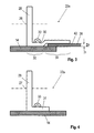
- FIG. 3 shows a schematic representation and in a partially sectioned side view in the FIG. 2 illustrated angle element 20a of the first type.
- the in the FIG. 2 shown angle elements 20a and 20b are the same. The following is based on the FIG. 3 only the angle elements 20a described.
- From the upper horizontal cover plate 14 is perpendicular to a leg 28 protrudes.
- the leg 28 is provided with a perpendicular thereto through-hole 26 for engaging carabiners.
- the fastening leg 30 has, adjacent to the leg 28, a fastening region 32 with which the angle element 20a is attached to the upper horizontal cover plate 14 of the control cabinet housing 10.
- a rivet 33 indicated.
- a (not shown) screw or welded connection could be provided.
- this has adjacent to the mounting portion 32, a holding portion 34, with which the mounting leg 30 engages behind an integrally formed on the roof 19 edge profile 36.
- the holding region 34 can be resiliently biased in an embodiment (not shown) with respect to the edge profile 36, so that in the installed state of the roof, a back pressure acts on the edge profile 36.
- the holding portion 34 of the mounting leg 30 is spaced from the upper horizontal cover plate 14 of the control cabinet housing 10 at a distance a, which substantially corresponds to the height h of the edge profile 36 of the roof 19.
- the distance a between the holding portion 34 of the mounting leg 30 and the cover plate 14 may be slightly larger than the height h of the edge profile 36 designed so that the edge profile 36 can engage in the distance range between the holding portion 34 of the mounting leg 30 and the cover plate 14 and also a tilted insertion of the edge profile 36 is possible.
- the holding portion 34 of the mounting leg 30 may (in an alternative embodiment not shown) project completely beyond the cover plate 14. In this case, the attachment region of the roof 19 in the region of the attachment leg 30 can be cut free so that the assembly process can be carried out by a tilting movement.
- the mounting leg 30 may be angled downwardly in the holding area 34, so that the mounting can be carried out as in the embodiment described above via a tilting operation, but in the mounted state via a spring action the roof 19 with a small back pressure is firmly secured to the cover plate 14 of the housing
- FIG. 2 in connection with the FIG. 3 shows, in the region of the rear wall 46 of the cabinet at the upper horizontal cover plate 14 arranged angle elements 20a and 20b of the first type with a portion of the holding portion 34 of the respective mounting leg 30 on the perimeter of the upper horizontal cover plate 14 of the cabinet housing 10 out.
- the support 42 of the edge profile 36 is defined between the mounting legs 30 of the two angle elements 20 a and 20 b and the upper horizontal cover plate 14 of the control cabinet housing 10.
- the roof 19 can be for mounting in a (not shown) shifted back position on the upper horizontal cover plate 14 of the control cabinet housing 10, with a tilt is possible, in which the front, the Cabinet door facing part of the roof 19 opposite the rear, the rear wall 46 facing part is raised.
- the support 42 of the edge profile 36 of the roof 19 is arranged in the direction away from the rear wall 46 perpendicular direction forward sparing.
- the support 42 of the edge profile 36 is not engaged with the holding portions 34 of the mounting legs 30 of the angle elements 20a and 20b.
- the support 42 of the edge profile 36 comes with the holding portions 34 of the mounting leg 30 of the angle elements 20 a and 20 b into engagement.
- FIG. 4 shows a schematic representation and in a partially sectioned side view in the FIG. 2 illustrated angle element 22a of the second type.
- the in the FIG. 2 shown angle elements 22a and 22b are the same. The following is based on the FIG. 4 only the angle elements 22a described.
- From the upper horizontal cover plate 14 is perpendicular a leg 29 protrudes.
- the leg 29 is provided with a perpendicular thereto through-hole 27 for engaging a carabiner.
- Parallel to the upper horizontal cover plate 14 extends a mounting leg 31, which adjoins the leg 29 at right angles.
- the angle element 22a of the second type is similar to that in FIG FIG. 3 shown angle element 20a of the first type.
- angle element 22a of the second type is in contrast to that in the FIG. 3 shown angle element 20a of the first type of the entire mounting leg 31 on the upper horizontal cover plate 14 of the control cabinet housing 10 and is fixed thereto.
- a rivet 33 indicated in the in the FIG. 4 embodiment shown again a rivet 33 indicated.
- a screw or welded connection could be provided.
- FIG. 5 shows a schematic representation and sectional side view of the roof area of the in FIG. 2 shown control cabinet.
- the roof 19 has a flat roof plate 38, which protrudes circumferentially beyond the upper horizontal cover plate 14 of the control cabinet housing 10 with an edge profile 36, as shown in the FIG. 2 becomes clear.
- the edge profile 36 has a circumferential, perpendicular to the upper horizontal cover plate 14 of the control cabinet housing 10 aligned soabkantung 40.
- the Soabkantung 40 has a perpendicular thereto in the direction of the center M of the upper horizontal cover plate 14 of the control cabinet housing 10 and parallel thereto support 42. With the support 42, the roof 19 rests on the edge region of the upper horizontal cover plate 14 of the control cabinet housing 10.
- the upper horizontal cover plate 14 rests on an upper frame of the control cabinet housing 10, of which in the illustration of FIG. 5 the upper depth stay 60 is shown.
- the support 42 has a plurality of ventilation slots 44, which are arranged in areas 45 which extend parallel to the cabinet door 13, the rear wall 46 and the side plates 48 of the control cabinet housing 10.
- the ventilation slots 44 extend perpendicular to the cabinet door 13, to the rear wall 46 and to the side plates 48 of the control cabinet housing 10.
- the legs 28 of the angle elements 20a, 20b and 22a, 22b are substantially in the direction of the two in the FIG. 2 drawn diagonals D1 and D2 of the upper horizontal cover plate 14 aligned.
- FIG. 6 shows in a schematic representation and sectional side view of the in FIG. 5 marked part IV in an enlarged view.
- the cabinet door beats in the in FIG. 6 shown closed position on a mounted on the cabinet housing 10, around the door opening encircled seal 62 at.
- the cabinet door has a door tube frame 64 to which the door panel is secured by a bolt 66 welded thereto.
- the upper horizontal cover plate 14 of the control cabinet housing 10 associated edge of the cabinet door 13 is bent perpendicularly in the direction of the cabinet housing 10, whereby a fold 55 is formed.
- a perpendicular thereto in the direction of the base 51 extending bevelled end portion 68 is formed.
- the perpendicular to the roof 19 in the direction of the bottom frame of the cabinet extending locking lug 52 is bent at its lower end perpendicular to the cabinet door 13, whereby a fold 57 is formed.
- a bevelled end region 70 which extends perpendicularly in the direction of the roof 19, is in turn formed.
- the support 42 of the edge profile 36 is in the area between the two angle elements 20a and 20b with a projecting support portion 56 toward the center M of the upper horizontal cover plate 14 of the control cabinet housing 10 and forms a widened support surface 47 of the roof 19 on the Edge region of the cover plate 14th
- FIG. 7 shows a schematic representation and in plan view of a control cabinet according to a second preferred embodiment, in which a roof 19 is placed on the upper horizontal cover plate 14 of the control cabinet housing 10 and secured by angle elements 24a, 24b, 24c and 24d.
- the roof panel is also in the representation of FIG. 7 omitted to view the look on the roof 19 molded edge profile 36 and the arrangement of the four angle elements 24a, 24b, 24c and 24d of the first type.
- FIG. 7 shows components already in the FIG. 2 have been given the same reference numerals and above in connection with the FIG. 2 have been described. These components are not described again below, because they have the same functionality as in the FIG. 2 shown components with the same reference numerals. Below are just the differences to the in FIG. 2 illustrated embodiment described.
- Two angle elements 24a and 24b of the basis of FIG. 3 already described first type are arranged on the upper horizontal cover plate 14 in the region of the rear wall 46 in the associated corner regions of the cover plate 14.
- Two further angle elements 24c and 24c of the same first type are arranged in the area of the control cabinet door 13 in the associated corner regions of the cover plate 14.
- the angle elements 24a, 24b, 24c and 24d have as the basis of the FIG. 3 described angle element 20a mounting leg 30 which rest with their mounting portions 32 on the upper horizontal cover plate 14 of the control cabinet housing 10 and secured thereto.
- the holding regions 34 are spaced from the upper horizontal cover plate 14 of the control cabinet housing 10, wherein the support 42 of the edge profile 36 between the mounting legs 30 of the angle elements 24a, 24b, 24c and 24d and the upper horizontal cover plate 14 of the control cabinet housing 10 are fixed.
- the support 42 of the edge profile 36 has four recesses 58, which are offset in the direction of the rear wall 46 of the control cabinet housing 10 and adjacent to the angle elements 24a, 24b, 24c and 24d are formed.
- the recesses 58 are formed corresponding to the holding portions 34 of the fastening legs 30 of the angle elements 24a, 24b, 24c and 24d.
- the roof 19 can be placed in a (not shown) position on the upper horizontal cover plate 14 of the control cabinet housing 10 so that the recesses 58 in the support 42 of the edge profile 36 with the holding portions 34 of the mounting leg 30 of the angle elements 24a, 24b , 24c and 24d are in cover. In this position, the support 42 of the edge profile 36 with the holding portions 34 of the mounting legs 30 of the angle elements 24a, 24b, 24c and 24d is disengaged.
- the support 42 of the edge profile 36 can be brought into engagement with the holding areas 34 of the fastening legs 30 of the angle elements 24a, 24b, 24c and 24d.
Landscapes
- Engineering & Computer Science (AREA)
- Power Engineering (AREA)
- Patch Boards (AREA)
- Casings For Electric Apparatus (AREA)
Abstract
Description
- Die Erfindung betrifft einen Schaltschrank mit einem Schaltschrankgehäuse, welches an seiner Oberseite durch ein oberes Abdeckblech begrenzt wird und an seiner Vorderseite mindestens eine Schaltschranktür aufweist. An der Oberseite des Schaltschrankgehäuses ist eine Mehrzahl von Transportösen angebracht, welche durch ein lösbar befestigbares Dach abdeckbar sind.
- Aus dem Rittal-Handbuch 32, Seite 879, ist ein so genanntes CS Basicgehäuse bekannt, welches im Wesentlichen aus einem Schaltschrankgehäuse mit mindestens einer Türe und einem zusätzlichen aufgesetzten Wetterschutz-Dach besteht. Derartige Schaltschränke sind insbesondere auch für den Außen-Einsatz konzipiert und sollen zum einen den Eintritt von Regenwasser in das Innere des Gehäuses und zum anderen einen gewissen Kühleffekt bei direkter Sonnenbestrahlung ermöglichen.
- Bei dem bekannten Schaltschrank besteht das Wetterschutz-Dach im Wesentlichen aus einem flächigen Dachblech, welches mit Hilfe eines separaten Winkelprofils an dem oberen Rahmengestell des Schaltschrankes bzw. an dessen oberen Abdeckblech angebracht ist. Das Winkelprofil ist am hinteren, dem Benutzer abgewandten Teil des Schaltschrankgehäuses mittels Schraubverbindungen befestigt. Seitlich schließt das Wetterschutz-Dach durch ebenfalls am Schaltschrankgehäuse befestigte, separate Seitenteilen ab, die wiederum durch Eckstücke mit dem Winkelprofil und dem Abdeckblech verbunden sind. An dem dem Benutzer zugewandten Teil des Schaltschrankgehäuses ist ein durch Eckstücke mit den beiden Seitenteilen verbundenes, separates Dach-Vorderteil, welches das Wetterschutz-Dach nach vorne hin begrenzt, angeschraubt.
- Der Montage- und Teileaufwand ist bei dem bekannten Schaltschrank nicht unerheblich. Dabei ist es insbesondere sehr aufwendig, das Wetterschutz-Dach für einen Transport abzunehmen und nach einen Transport wieder aufzusetzen und zu befestigen. Denn für einen Transport sind an der oberen Abdeckung des Schaltschanks an dessen oberen Rahmenprofil in den Eckbereichen vier Ringschrauben in entsprechende Bohrungen eingeführt und verschraubt. Diese Ringschrauben dienen als so genannte Transport- oder Kranösen, in welche beispielsweise mittels Karabinern vier Transportseile angehängt werden können, die wiederum mittig zusammengeführt und von einem Kran aufgenommen werden können. Die Kranösen sind bei aufgesetztem Wetterschutz-Dach durch dieses abgedeckt, so dass das Wetterschutz-Dach gleichzeitig als Vandalen- oder Diebstahlschutz dient. Bei dem bekannten Schaltschrank sind die Kranösen als sehr schwere, separat einzuschraubende Bauteile ausgebildet, deren Montage am Schaltschrankgehäuse aufwendig ist und eine erhebliches Mehrgewicht bedeuten.
- Es ist Aufgabe der Erfindung, einen Schaltschrank mit einem aufgesetzten Dach anzugeben, welches auf einfache Weise und mit einem geringen Teileaufwand lösbar am Schaltschrankgehäuse montierbar ist.
- Darüber hinaus soll der erfindungsgemäße Schaltschrank im Bereich des aufgesetzten Daches eine Transporteinrichtung aufweisen, die Gewicht und Material sparend ausgeführt ist und dennoch im Wesentlichen dieselbe Traglast wie herkömmliche Ringschrauben erlaubt.
- Diese Aufgabe der Erfindung wird durch einen Schaltschrank mit den Merkmalen des Anspruchs 1 gelöst. Die Unteransprüche betreffen vorteilhafte Weiterbildungen des erfindungsgemäßen Schaltschranks.
- Demgemäß sind die Transportösen durch Winkelelemente gebildet. Die Winkelelemente weisen jeweils einen von dem oberen Abdeckblech hervorstehenden, mit einer Durchgangsbohrung versehenen Schenkel und einen dazu im Winkel stehenden Befestigungsschenkel auf. Die Befestigungsschenkel mindestens eines Teils der Winkelelemente weisen jeweils einen Befestigungsbereich auf, mit welchem die Winkelelemente an der Oberseite des Schaltschrankgehäuses angebracht ist. Weiterhin weisen die Winkelelemente jeweils einen Haltebereich auf, mit welchem die Winkelelemente ein an dem aufgesetzten Dach angeformtes Randprofil hintergreifen.
- Das auf das Schaltschrankgehäuse aufgesetzte Dach lässt sich auf einfache Weise und mit einem geringen Teileaufwand lösbar am Schaltschrankgehäuse montieren. Der Schaltschrank weist im Bereich des aufgesetzten Daches eine Transporteinrichtung auf, die eine Doppelfunktion erfüllt. Zum einen dienen die einschenklig durchbohrten Winkelelemente als Transport- oder Kranösen, zum anderen sichern die Winkelelemente das Dach gegen Abheben. Die Winkelelemente können auf einfache Weise am Schaltschrankgehäuse angeschraubt, vernietet oder mit diesem verschweißt werden Dabei sind die Winkelelemente, die im Wesentlichen aus einem abgekanteten Metallblech vorbestimmter Stärke bestehen können Gewicht und Material sparend ausgeführt. Je nach Montagestellung und Wahl des Materials und der Materialstärke weisen die Winkelemente im Wesentlichen dieselbe Traglast wie herkömmliche Ringschrauben auf.
- Der Haltebereich kann gegenüber dem Randprofil federelastisch vorgespannt sein, so dass im montierten Zustand des Daches ein Gegendruck auf das Randprofil wirkt. Dieser Gegendruck sicher das Dach in seiner Montageposition.
- Ein Teil der nur als Transporteinrichtung verwendeten Winkelelemente kann auch folgendermaßen aufgebaut sein: Der Schenkel, der von dem oberen Abdeckblech hervorsteht, weist eine Durchgangsbohrung auf. Der Befestigungsschenkel, der zum Schenkel in einem Winkel steht, liegt an dem oberen Abdeckblech des Schaltschrankgehäuses im Wesentlichen ganzflächig an und ist an diesem befestigt. Ein derartiges Winkelelement dient als Transport- oder Kranöse, leistet jedoch keinen Beitrag zur Sicherung des Daches.
- Um eine besonders hohe Tragkraft der Transporteinrichtung zu erreichen, können die Schenkel der oder aller verwendeten Winkelelemente im Wesentlichen in Richtung der Diagonalen des oberen Abdeckblechs ausgerichtet sein. Diese diagonale Ausrichtung der Kranösen ermöglicht es, mit geringem Materialeinsatz und dünneren Materialien gleiche Hubbelastungen wie bei der Verwendung von Ringschrauben zu realisieren, denn unabhängig vom Seilwinkel beim Transport wird die Kraft immer auf der Blechebenen eingeleitet. Zudem können die Winkelelemente besonders kleinbauend ausgeführt sein. Die Haltebereiche der Befestigungsschenkel der Winkelelemente, die zur Sicherung des Daches eingesetzt werden, können dabei so ausgelegt sein, dass das am aufgesetzten Dach angeformte Randprofil sicher hintergriffen bzw. gesichert wird.
- Das Dach kann ein flächiges Dachblech aufweisen, welches umfangsmäßig über das obere Abdeckblech des Schaltschrankgehäuses, d.h. über dessen Vorder- und Rückseite und die Seitenteile mit einem Randprofil hervorsteht. Das Randprofil weist eine umlaufende, sich in Richtung auf das obere Abdeckblech, d.h. in Richtung des Sockels des Schaltschrankgehäuses ausgerichtete Seitenabkantung aufweist.
- Die Seitenabkantung weist wiederum eine dazu in Richtung auf die Mitte des oberen Abdeckblechs des Schaltschrankgehäuses abgekantete Auflage auf. Mit der Auflage liegt das Dach von oben her am Randbereich des oberen Abdeckblechs des Schaltschrankgehäuses auf.
- Die Auflage kann Lüftungsschlitze aufweisen, um beispielsweise unter dem Dach aufgrund von Sonneneinstrahlung angestaute warme Luft abzuleiten. Die Lüftungsschlitze können in Bereichen angeordnet sein, die sich zumindest teilweise parallel zur Schaltschranktür, zur Rückwand und zu den Seitenblechen des Schaltschrankgehäuses erstrecken. Dabei kann eine Mehrzahl von Lüftungsschlitzen senkrecht zur Schaltschranktür, zur Rückwand und zu den Seitenblechen des Schaltschrankgehäuses verlaufen.
- Gemäß einer Ausführungsform der Erfindung kann die Auflage des am Dach angeformten Randprofils zwischen den Befestigungsschenkeln mindestens zweier Winkelelemente und dem oberen Abdeckblech des Schaltschrankgehäuses festgelegt sein. Dies ermöglicht zumindest eine einseitige Sicherung gegen Abheben des Daches vom Schaltschrankgehäuse.
- In vorteilhafter Weise können dabei zumindest zwei der Winkelelemente mit zumindest einem Teil der Haltebereiche der Befestigungsschenkel über die Umfangsbegrenzung des oberen Abdeckblechs des Schaltschrankgehäuses hervorstehen. Mit dem hervorstehenden Teil der Befestigungsschenkel kann dadurch eine einseitige Sicherung geschaffen werden, in die das Dach bei der Montage auf einfache Weise vorzugsweise in einer gegenüber dem oberen Abdeckblech verkippten Stellung eingehängt werden kann.
- Um wirkungsvoll zu verhindern, dass das Dach von Unberechtigten gegenüber dem Schaltschrankgehäuse verschoben wird, kann an dem der Schaltschranktür zugewandten Bereich des Randprofils des Daches ein sich vom Dach in Richtung auf den Bodenrahmen des Schaltschranks erstreckender Verriegelungsansatz angeformt sein. Dieser Verriegelungsansatz erstreckt sich bei geschlossener Schaltschranktür in den Abstandsbereich zwischen der Schaltschranktür und dem Schaltschrankgehäuse hinein. Dadurch wird bei geschlossener Schaltschranktür ein Verschieben des Daches gegenüber dem oberen Abdeckblech in Richtung der Schaltschranktür verhindert. Mit diesen einfachen Maßnahmen wird vermieden, dass das Dach durch Schraubverbindungen gesichert werden muss. Somit wird der Montage- und gegebenenfalls auch Demontageaufwand erheblich reduziert und zusätzlich Material eingespart.
- Um zusätzlichwirkungsvoll zu verhindern, dass das Dach von Unberechtigten vom Schaltschrankgehäuse abgehoben wird, kann der dem oberen Abdeckblech des Schaltschrankgehäuses zugeordnete Rand der Schaltschranktür in Richtung auf das Schaltschrankgehäuse abgekantet sein. Dabei ist der sich vom Dach in Richtung auf den Bodenrahmen des Schaltschranks erstreckender Verriegelungsansatz an seinem unteren Ende in Richtung auf die Schaltschranktür abgekantet. Falls ein Unberechtigter versuchen sollte, das Dach im vorderen, der Schaltschranktür zugeordneten Bereich abzuheben, werden die beiden sich gegenüberstehenden Abkantungen der geschlossenen Schaltschranktür und des Verriegelungsansatzes aufeinander treffen und ein weiteres Abheben verhindern.
- Der Teil der Winkelelemente, die in ihrer Doppelfunktion als Transport- oder Kranöse und als Dachsicherung verwendet werden, kann auch folgendermaßen aufgebaut sein: Der Befestigungsbereich des Befestigungsschenkels des Winkelelements liegt am oberen Abdeckblech des Schaltschrankgehäuses an und ist an diesem befestigt. Der Haltebereich des Befestigungsschenkels ist von dem oberen Abdeckblech des Schaltschrankgehäuses in einem Abstand beabstandet, welcher im Wesentlichen der Höhe der Auflage des Randprofils des Daches entspricht.
- Die Auflage des am Dach angeformten Randprofils kann dabei durch Verschieben gegenüber dem oberen Abdeckblech auf einfache Weise in den Abstandsbereich zwischen dem oberen Abdeckblech und dem Haltebereich des Befestigungsschenkels des Winkelelements eingeführt werden. Dies sichert das Dach wirkungsvoll gegen Abheben.
- Gemäß einer ersten bevorzugten Ausführungsform der Erfindung können mindestens zwei Winkelelemente eines ersten Typs am oberen Abdeckblech im Bereich der von der Schaltschranktür abgewandten Rückwand angeordnet sein. Zusätzlich sind mindestens zwei Winkelelemente eines zweiten Typs im Bereich der Tür des Schaltschrankgehäuses angeordnet und dort befestigt.
- Die Winkelelemente des ersten Typs sind dabei folgendermaßen ausgeführt und positioniert: Die Befestigungsschenkeln liegen mit ihren Befestigungsbereichen am oberen Abdeckblech des Schaltschrankgehäuses an und sind an diesem befestigt. Die Haltebereiche sind vom oberen Abdeckblech des Schaltschrankgehäuses beabstandet und stehen über die Umfangsbegrenzung des oberen Abdeckblechs hervor. Damit kann die Auflage des Randprofils zwischen den Befestigungsschenkeln der zwei Winkelelemente des ersten Typs und dem oberen Abdeckblech des Schaltschrankgehäuses sicher festgelegt werden.
- Die Winkelelemente des zweiten Typs weisen dabei Befestigungsschenkel auf, die am oberen Abdeckblech des Schaltschrankgehäuses im Wesentlichen vollflächig anliegen.
- Um eine verbreiterte Auflagefläche zwischen dem am Dach angeformten Randprofil und der Oberseite des Schaltschrankgehäuses zu schaffen, kann die Auflage des Randprofils, die im Bereich zwischen den beiden Winkelelementen des ersten Typs ausgebildet ist, mit einem vorstehenden Auflagebereich in Richtung auf die Mitte des oberen Abdeckblechs des Schaltschrankgehäuses hervorstehen.
- Für eine einfache Montage kann das Dach in einer Position auf das obere Abdeckblech des Schaltschrankgehäuses aufgesetzt werden, in welcher das Dach um ein gewisses Stück in Richtung der Schaltschrankrückwand verschoben ist. In dieser nach hinten verschobenen Position ist die im Bereich der von der Schaltschranktür abgewandten Rückwand angeordnete Auflage des Randprofils des Daches in von der Rückwand wegweisenden Richtung angeordnet. Dabei kommt die Auflage des Randprofils nicht mit den Haltebereichen der Befestigungsschenkel der Winkelelemente des ersten Typs in Eingriff. Wenn das Dach in Richtung auf die Schaltschranktür hin, d.h. nach vorne verschoben wird, kommt die Auflage des Randprofils mit den Haltebereichen der Befestigungsschenkel der Winkelelemente des ersten Typs in Eingriff, so dass eine Sicherung des Daches gegen Abheben geschaffen ist.
- Gemäß einer zweiten bevorzugten Ausführungsform können mindestens zwei Winkelelemente am oberen Abdeckblech im Bereich der von der Schaltschranktür abgewandten Rückwand und mindestens zwei weitere Winkelelemente im Bereich der Tür des Schaltschrankgehäuses angeordnet sein. Die Winkelelemente sind dabei alle vom selben Typ, der dem ersten Typ der ersten bevorzugten Ausführungsform entsprechen kann. Die Winkelelemente sind dabei folgendermaßen ausgeführt: Die Befestigungsschenkel liegen mit ihren Befestigungsbereichen am oberen Abdeckblech des Schaltschrankgehäuses an und sind an diesem befestigt. Die Haltebereiche sind vom oberen Abdeckblech des Schaltschrankgehäuses beabstandet, wobei die Auflage des Randprofils zwischen den Befestigungsschenkeln der Winkelelemente und dem oberen Abdeckblech des Schaltschrankgehäuses festlegbar ist.
- Um eine einfache Montage und gegebenenfalls auch eine einfache Demontage des Daches zu ermöglichen, kann die Auflage des Randprofils Ausnehmungen aufweisen, die in Richtung der Rückwand des Schaltschrankgehäuses benachbart zu den Winkelelementen und korrespondierend zu den Haltebereichen der Befestigungsschenkel der Winkelelemente ausgeformt sind.
- Für eine einfache Montage kann das Dach in einer Position auf das obere Abdeckblech des Schaltschrankgehäuses aufgesetzt werden, in welcher das Dach um ein gewisses Stück in Richtung der Schaltschranktür verschoben ist. In dieser Position sind die Ausnehmungen in der Auflage des Randprofils mit den Haltebereichen der Befestigungsschenkel der Winkelelemente in Deckung. Dabei stehen die Auflage des Randprofils mit den Haltebereichen der Befestigungsschenkel der Winkelelemente nicht in Eingriff. Wenn das Dach in Richtung auf die Rückwand des Schaltschrankgehäuses hin verschoben wird, kommt die Auflage des Randprofils mit den Haltebereichen der Befestigungsschenkel in Eingriff, so dass eine Sicherung des Daches gegen Abheben geschaffen ist.
- Der sich vom Dach in Richtung auf den Bodenrahmen des Schaltschrankgehäuses erstreckende Verriegelungsansatz kann bei Verschiebung des Daches in Richtung der Rückwand des Schaltschrankgehäuses am Schaltschrankgehäuse anschlagen. Damit wird zum einen ein Verschieben des Daches in Richtung der Schaltschrankrückwand begrenzt, zum anderen wird bei geschlossener Tür verhindert, dass das Dach in Richtung auf die Schaltschranktür verschoben werden kann.
- Nachfolgend wird die Erfindung anhand von bevorzugten Ausführungsformen unter Bezugnahme auf die beigefügten Zeichnungen näher erläutert.
- Es zeigen:
- Figur 1
- in schematischer Darstellung und in perspektivischer Ansicht einen Schaltschrank mit einem Schaltschrankgehäuse, an welchem eine Schaltschranktür, ein Sockel und ein Dach angebracht angebracht werden;
- Figur 2
- in schematischer Darstellung und in Draufsicht einen Schaltschrank gemäß einer ersten bevorzugten Ausführungsform, bei der ein Dach auf das obere horizontale Abdeckblech des Schaltschrankgehäuses aufgesetzt und durch Winkelelemente gesichert ist, wobei das Dachblech in der Darstellung ausgelassen ist, um den Blick auf das am Dach angeformte Randprofil und die Anordnung zweier unterschiedlicher Typen von Winkelelementen freizugeben;
- Figur 3
- in schematischer Darstellung und in teilweise geschnittener Seitenansicht ein in der
Figur 2 dargestelltes Winkelelement des ersten Typs; - Figur 4
- in schematischer Darstellung und in teilweise geschnittener Seitenansicht ein in der
Figur 2 dargestelltes Winkelelement des zweiten Typs; - Figur 5
- in schematischer Darstellung und geschnittener Seitenansicht den Dachbereich des in der
Figur 2 dargestellten Schaltschrankes; - Figur 6
- in schematischer Darstellung und geschnittener Seitenansicht den in der
Figur 5 gekennzeichneten Teil IV in vergrößerter Darstellung; und - Figur 7
- in schematischer Darstellung und in Draufsicht einen Schaltschrank gemäß einer zweiten bevorzugten Ausführungsform, bei der ein Dach auf das obere horizontale Abdeckblech des Schaltschrankgehäuses aufgesetzt und durch Winkelelemente gesichert ist, wobei das Dachblech in der Darstellung ausgelassen ist, um den Blick auf das am Dach angeformte Randprofil und die Anordnung von vier Winkelelementen des ersten Typs freizugeben.
- Die
Figur 1 zeigt in schematischer Darstellung und in perspektivischer Ansicht einen Schaltschrank mit einem Schaltschrankgehäuse 10. Das Schaltschrankgehäuse 1.0 ist an seiner Oberseite 12 durch ein oberes, sich horizontal zum (nicht dargestellten) Boden erstreckendes Abdeckblech 14 begrenzt. An der Vorderseite 16 weist der Schaltschrank eine Schaltschranktür 13 auf, die an am Schaltschrankgehäuse angebrachten Scharnieren 53 angelenkt werden. Am unteren Ende wird das Schaltschrankgehäuse 10 mit seinem nach unten offenen Bodenrahmen 50 auf einen Sockel 51 aufgesetzt, mit welchem der Schaltschrank auf dem Boden aufgestellt ist. - An der Oberseite 12 des Schaltschrankgehäuses 10 sind vier Transportösen 18 angebracht, die durch Winkelelemente gebildet sind, von denen in der
Figur 1 nur die Winkelelemente mit den Bezugszeichen 24a, 24c und 24d dargestellt sind. An der Oberseite 12 des Schaltschrankgehäuses 10 wird ein Wetterschutz-Dach 19 auf das obere horizontalen Abdeckblech 14 aufgesetzt, das mit dem Schaltschrankgehäuses 10 lösbar verbunden wird. Das Dach 19 deckt im (inFigur 1 nicht gezeigten) montierten Zustand die Transportösen 18 ab. - Die
Figur 2 zeigt in schematischer Darstellung und in Draufsicht einen Schaltschrank gemäß einer ersten bevorzugten Ausführungsform, bei der das Dach 19 auf das obere horizontale Abdeckblech 14 des Schaltschrankgehäuses 10 aufgesetzt und durch Winkelelemente 20a, 20b eines ersten Typs (der nachfolgend anhand derFigur 3 näher beschrieben wird) gesichert ist. Die Winkelelement 22a und 22b eines vom ersten Typ unterschiedlichen zweiten Typs (der nachfolgend anhand derFigur 4 näher beschrieben wird) dienen nicht der Sicherung des Daches 19, sondern sind ausschließlich als Transport- bzw. Kranösen ausgebildet. Das Dachblech des Daches 19 ist in der Darstellung derFigur 2 ausgelassen, um den Blick auf das am Dach 19 angeformte Randprofil 36 und die Anordnung der Winkelelemente 20a, 20b des ersten Typs und der Winkelelemente 22a, 22b des zweiten Typs freizugeben. - Zwei Winkelelemente 20a und 20b des ersten Typs sind am oberen horizontalen Abdeckblech 14 im Bereich der von der Schaltschranktür 13 abgewandten Rückwand 46 in den zugeordneten Eckbereichen des Abdeckblechs 14 angeordnet.
- Zwei Winkelelemente 22a und 22b des zweiten Typs sind am oberen horizontalen Abdeckblech 14 im Bereich der Schaltschranktür 13 des Schaltschrankgehäuses 10 in den zugeordneten Eckbereichen des Abdeckblechs 14 angeordnet und dort befestigt.
- Die
Figur 3 zeigt in schematischer Darstellung und in teilweise geschnittener Seitenansicht ein in derFigur 2 dargestelltes Winkelelement 20a des ersten Typs. Die in derFigur 2 gezeigten Winkelelemente 20a und 20b sind gleich ausgebildet. Nachfolgend wird anhand derFigur 3 nur das Winkelelemente 20a beschrieben. Von dem oberen horizontalen Abdeckblech 14 steht senkrecht ein Schenkel 28 hervor. Der Schenkel 28 ist mit einer senkrecht dazu angebrachten Durchgangsbohrung 26 zum Eingreifen von Karabinern versehen. - Parallel zum oberen horizontalen Abdeckblech 14 erstreckt sich ein Befestigungsschenkel 30, der sich im rechten Winkel an den Schenkel 28 anschließt. Der Befestigungsschenkel 30 weist angrenzend an den Schenkel 28 einen Befestigungsbereich 32 auf, mit welchem das Winkelelement 20a am oberen horizontalen Abdeckblech 14 des Schaltschrankgehäuses 10 angebracht ist. Zu diesem Zweck ist bei der in der
Figur 3 gezeigten Ausführungsform eine Nietverbindung 33 angedeutet. Alternativ könnte auch eine (nicht gezeigte) Schraub- oder Schweißverbindung vorgesehen sein. In Richtung des freien Endes des Befestigungsschenkels 30 weist dieser angrenzend an den Befestigungsbereich 32 einen Haltebereich 34 auf, mit welchem der Befestigungsschenkels 30 ein am Dach 19 angeformtes Randprofil 36 hintergreift. - Der Haltebereich 34 kann in einer (nicht gezeigten) Ausführungsform gegenüber dem Randprofil 36 federelastisch vorgespannt sein, so dass im montierten Zustand des Daches ein Gegendruck auf das Randprofil 36 wirkt.
- Der Haltebereich 34 des Befestigungsschenkels 30 ist von dem oberen horizontalen Abdeckblech 14 des Schaltschrankgehäuses 10 in einem Abstand a beabstandet, welcher im Wesentlichen der Höhe h des Randprofils 36 des Daches 19 entspricht.
- Der Abstand a zwischen dem Haltebereich 34 des Befestigungsschenkels 30 und dem Abdeckblech 14 kann dabei geringfügig größer als die Höhe h des Randprofils 36 ausgelegt sein, damit das Randprofil 36 in den Abstandsbereich zwischen dem Haltebereich 34 des Befestigungsschenkels 30 und dem Abdeckblech 14 eingreifen kann und auch ein verkipptes Einführen des Randprofils 36 möglich ist.
- Der Haltebereich 34 des Befestigungsschenkels 30 kann (in einer nicht gezeigten) alternativen Ausführungsform komplett über den Abdeckblech 14 hervorstehen. Dabei kann der Befestigungsbereich des Daches 19 im Bereich der Befestigungsschenkels 30 so freigeschnitten sein, dass der Montagevorgang durch eine Kippbewegung durchgeführt werden kann.
- In einer weiteren (nicht gezeigten) Ausführungsform kann der Befestigungsschenkel 30 im Haltebereich 34 nach unten angewinkelt sein, so das die Montage nach wie bei der vorstehend beschriebenen Ausführungsform über einen Kippvorgang durchgeführt werden kann, wobei jedoch im montierten Zustand über eine Federwirkung das Dach 19 mit einem kleinen Gegendruck fest auf das Abdeckblech 14 des Gehäuses gesichert wird
- Wie die
Figur 2 im Zusammenhang mit derFigur 3 zeigt, stehen die im Bereich der Rückwand 46 des Schaltschrankes am oberen horizontalen Abdeckblech 14 angeordneten Winkelelemente 20a und 20b des ersten Typs mit einem Teil des Haltebereichs 34 des jeweiligen Befestigungsschenkels 30 über die Umfangsbegrenzung des oberen horizontalen Abdeckblechs 14 des Schaltschrankgehäuses 10 hervor. Die Auflage 42 des Randprofils 36 ist zwischen den Befestigungsschenkeln 30 der zwei Winkelelemente 20a und 20b und dem oberen horizontalen Abdeckblech 14 des Schaltschrankgehäuses 10 festgelegt. - Das Dach 19 lässt sich für die Montage in einer (nicht gezeigte) nach hinten verschobenen Position auf das obere horizontale Abdeckblech 14 des Schaltschrankgehäuses 10 aufsetzen, wobei eine Verkippung möglich ist, bei der das vordere, der Schaltschranktür zugewandte Teil des Daches 19 gegenüber dem hinteren, der Rückwand 46 zugewandten Teil angehoben ist. In dieser Position ist die Auflage 42 des Randprofils 36 des Daches 19 in von der Rückwand 46 senkrecht wegweisenden Richtung nach hinten verschonen angeordnet. Die Auflage 42 des Randprofils 36 steht dabei mit den Haltebereichen 34 der Befestigungsschenkel 30 der Winkelelemente 20a und 20b nicht in Eingriff. Wenn das Dach 19 in Richtung auf die Schaltschranktür 13 verschoben wird, kommt die Auflage 42 des Randprofils 36 mit den Haltebereichen 34 der Befestigungsschenkel 30 der Winkelelemente 20a und 20b in Eingriff.
- Die
Figur 4 zeigt in schematischer Darstellung und in teilweise geschnittener Seitenansicht ein in derFigur 2 dargestelltes Winkelelement 22a des zweiten Typs. Die in derFigur 2 gezeigten Winkelelemente 22a und 22b sind gleich ausgebildet. Nachfolgend wird anhand derFigur 4 nur das Winkelelemente 22a beschrieben. Von dem oberen horizontalen Abdeckblech 14 steht senkrecht ein Schenkel 29 hervor. Der Schenkel 29 ist mit einer senkrecht dazu angebrachten Durchgangsbohrung 27 zum Eingreifen eines Karabiners versehenen. Parallel zum oberen horizontalen Abdeckblech 14 erstreckt sich ein Befestigungsschenkel 31, der sich im rechten Winkel an den Schenkel 29 anschließt. Insoweit gleicht das Winkelelement 22a des zweiten Typs dem in derFigur 3 gezeigten Winkelelement 20a des ersten Typs. - Bei dem in der
Figur 4 gezeigten Winkelelement 22a des zweiten Typs liegt im Gegensatz zu dem in derFigur 3 gezeigten Winkelelement 20a des ersten Typs der gesamte Befestigungsschenkel 31 an dem oberen horizontalen Abdeckblech 14 des Schaltschrankgehäuses 10 an und ist an diesem befestigt. Zu diesem Zweck ist bei der in derFigur 4 gezeigten Ausführungsform wiederum eine Nietverbindung 33 angedeutet. Alternativ könnte auch eine (nicht gezeigte) Schraub- oder Schweißverbindung vorgesehen sein. - Die
Figur 5 zeigt in schematischer Darstellung und geschnittener Seitenansicht den Dachbereich des in derFigur 2 dargestellten Schaltschrankes. - Das Dach 19 weist ein flächiges Dachblech 38 auf, welches umfangsmäßig über das obere horizontale Abdeckblech 14 des Schaltschrankgehäuses 10 mit einem Randprofil 36 hervorsteht, wie anhand der
Figur 2 deutlich wird. Das Randprofil 36 weist eine umlaufende, sich senkrecht in Richtung auf das obere horizontale Abdeckblech 14 des Schaltschrankgehäuses 10 ausgerichtete Seitenabkantung 40 auf. Die Seitenabkantung 40 weist eine dazu senkrecht in Richtung auf die Mitte M des oberen horizontalen Abdeckblechs 14 des Schaltschrankgehäuses 10 und parallel dazu verlaufende Auflage 42 auf. Mit der Auflage 42 liegt das Dach 19 am Randbereich des oberen horizontale Abdeckblechs 14 des Schaltschrankgehäuses 10 auf. - Das obere horizontale Abdeckblech 14 liegt auf einem oberen Rahmengestell des Schaltschrankgehäuses 10 auf, von dem in der Darstellung der
Figur 5 die obere Tiefenstrebe 60 gezeigt ist. - Wie die
Figur 2 im Zusammenhang mit derFigur 3 zeigt, ist die Auflage 42 des Randprofils 36 zwischen den Befestigungsschenkeln 30 der zwei Winkelelemente 20a und 20b und dem oberen horizontalen Abdeckblech 14 des Schaltschrankgehäuses 10 festgelegt. - Die Auflage 42 weist mehrere Lüftungsschlitze 44 auf, die in Bereichen 45 angeordnet sind, die sich parallel zur Schaltschranktür 13, zur Rückwand 46 und zu den Seitenblechen 48 des Schaltschrankgehäuses 10 erstrecken. Die Lüftungsschlitze 44 erstrecken sich senkrecht zur Schaltschranktür 13, zur Rückwand 46 bzw. zu den Seitenblechen 48 des Schaltschrankgehäuses 10.
- Die Schenkel 28 der Winkelelemente 20a, 20b und 22a, 22b sind im Wesentlichen in Richtung der beiden in die
Figur 2 eingezeichneten Diagonalen D1 und D2 des oberes horizontalen Abdeckblechs 14 ausgerichtet. - Die
Figur 6 zeigt in schematischer Darstellung und geschnittener Seitenansicht den in derFigur 5 gekennzeichneten Teil IV in vergrößerter Darstellung. - An dem der Schaltschranktür 13 zugewandten Bereich des Randprofils 36 des Daches 19 ist ein sich senkrecht vom Dach 19 in Richtung auf den Bodenrahmen 50 des Schaltschranks erstreckender Verriegelungsansatz 52 angeformt, der sich in den Abstandsbereich 54 zwischen der Schaltschranktür 13 und dem Schaltschrankgehäuse 10 hineinerstreckt. Bei geschlossener Schaltschranktür 13 ist, wie die
Figur 6 zeigt, ein Verschieben des Daches 19 parallel zum oberen horizontalen Abdeckblech 14 in Richtung der Schaltschranktür 13 verhindert ist. - Die Schaltschranktür schlägt in der in
Figur 6 gezeigten geschlossenen Stellung an einer am Schaltschrankgehäuse 10 angebrachten, um die Türöffnung umlaufenen Dichtung 62 an. Die Schaltschranktür weist einen Türrohrrahmen 64 auf, an der das Türblech mittels eines daran angeschweißten Bolzens 66 befestigt ist. - Der dem oberen horizontalen Abdeckblech 14 des Schaltschrankgehäuses 10 zugeordnete Rand der Schaltschranktür 13 ist senkrecht in Richtung auf das Schaltschrankgehäuse 10 abgekantet, wodurch eine Abkantung 55 gebildet ist. An der Abkantung 55 ist wiederum ein sich dazu senkrecht in Richtung des Sockels 51 erstreckender abgekanteter Endbereich 68 angeformt. Der sich senkrecht vom Dach 19 in Richtung auf den Bodenrahmen des Schaltschranks erstreckender Verriegelungsansatz 52 ist an seinem unteren Ende senkrecht in Richtung auf die Schaltschranktür 13 abgekantet, wodurch eine Abkantung 57 gebildet ist. An der Abkantung 57 ist wiederum ein sich dazu senkrecht in Richtung des Daches 19 erstreckender abgekanteter Endbereich 70 angeformt.
- Wie anhand der
Figur 2 deutlich wird, steht die Auflage 42 des Randprofils 36 im Bereich zwischen den beiden Winkelelementen 20a und 20b mit einem vorstehenden Auflagebereich 56 in Richtung auf die Mitte M des oberen horizontalen Abdeckblechs 14 des Schaltschrankgehäuses 10 hervor und bildet eine verbreiterte Auflagefläche 47 des Daches 19 auf dem Randbereich des Abdeckblechs 14. -
Figur 7 zeigt in schematischer Darstellung und in Draufsicht einen Schaltschrank gemäß einer zweiten bevorzugten Ausführungsform, bei der ein Dach 19 auf das obere horizontale Abdeckblech 14 des Schaltschrankgehäuses 10 aufgesetzt und durch Winkelelemente 24a, 24b, 24c und 24d gesichert ist. Das Dachblech ist auch in der Darstellung derFigur 7 ausgelassen, um den Blick auf das am Dach 19 angeformte Randprofil 36 und die Anordnung der vier Winkelelemente 24a, 24b, 24c und 24d des ersten Typs freizugeben. - Die
Figur 7 zeigt Komponenten, welche bereits in derFigur 2 mit denselben Bezugszeichen versehen wurden und vorstehend im Zusammenhang mit derFigur 2 beschrieben worden sind. Diese Komponenten werden nachfolgend nicht nochmals beschrieben, denn sie haben dieselbe Funktionalität wie die in derFigur 2 dargestellten Komponenten mit denselben Bezugszeichen. Nachfolgend werden nur die Unterschiede zu der inFigur 2 dargestellten Ausführungsform beschrieben. - Zwei Winkelelemente 24a und 24b des anhand der
Figur 3 bereits beschriebenen ersten Typs sind am oberen horizontalen Abdeckblech 14 im Bereich der Rückwand 46 in den zugeordneten Eckbereichen des Abdeckblechs 14 angeordnet. Zwei weitere Winkelelemente 24c und 24c desselben ersten Typs sind im Bereich der Schaltschranktür 13 in den zugeordneten Eckbereichen des Abdeckblechs 14 angeordnet. - Die Winkelelemente 24a, 24b, 24c und 24d weisen wie das anhand der
Figur 3 beschriebene Winkelelement 20a Befestigungsschenkel 30 auf, die mit ihren Befestigungsbereichen 32 am oberen horizontalen Abdeckblech 14 des Schaltschrankgehäuses 10 anliegen und an diesem befestigt sind. Die Haltebereiche 34 sind vom oberen horizontalen Abdeckblech 14 des Schaltschrankgehäuses 10 beabstandet, wobei die Auflage 42 des Randprofils 36 zwischen den Befestigungsschenkeln 30 der Winkelelemente 24a, 24b, 24c und 24d und dem oberen horizontalen Abdeckblech 14 des Schaltschrankgehäuses 10 festgelegt sind. - Die Auflage 42 des Randprofils 36 weist vier Ausnehmungen 58 auf, die in Richtung der Rückwand 46 des Schaltschrankgehäuses 10 versetzt und benachbart zu den Winkelelementen 24a, 24b, 24c und 24d ausgeformt sind. Die Ausnehmungen 58 sind korrespondierend zu den Haltebereichen 34 der Befestigungsschenkel 30 der Winkelelemente 24a, 24b, 24c und 24d ausgebildet.
- Für die Montage lässt sich das Dach 19 in einer (nicht gezeigten) Position auf das obere horizontale Abdeckblech 14 des Schaltschrankgehäuses 10 so aufsetzen, dass die Ausnehmungen 58 in der Auflage 42 des Randprofils 36 mit den Haltebereichen 34 der Befestigungsschenkel 30 der Winkelelemente 24a, 24b, 24c und 24d in Deckung sind. In dieser Position steht die Auflage 42 des Randprofils 36 mit den Haltebereichen 34 der Befestigungsschenkel 30 der Winkelelemente 24a, 24b, 24c und 24d außer Eingriff. Wenn das Dach 19 in Richtung auf die Rückwand 46 des Schaltschrankgehäuses 10 hin verschoben wird, lässt sich die Auflage 42 des Randprofils 36 mit den Haltebereichen 34 der Befestigungsschenkel 30 der Winkelelemente 24a, 24b, 24c und 24d in Eingriff bringen.
- Der in der
Figur 6 gezeigte, sich senkrecht vom Dach 19 in Richtung auf den Bodenrahmen 50 des Schaltschrankgehäuses 10 erstreckende Verriegelungsansatz 52 schlägt bei Verschiebung des Daches 19 in Richtung der Rückwand 46 des Schaltschrankgehäuses 10 am Schaltschrankgehäuse 10 an.
Claims (19)
- Schaltschrank mit einem Schaltschrankgehäuse (10), welches an seiner Oberseite (12) durch ein oberes Abdeckblech (14) begrenzt wird und an seiner Vorderseite (16) mindestens eine Schaltschranktür (13) aufweist, wobei an der Oberseite (12) des Schaltschrankgehäuses (10) eine Mehrzahl von Transportösen (18) angebracht ist, welche durch ein lösbar befestigbares Dach (19) abdeckbar sind,
dadurch gekennzeichnet,
dass die Transportösen (18) durch Winkelelemente (20a, 20b, 22a, 22b; 24a, 24b, 24c, 24d) gebildet sind, die jeweils einen von dem oberen Abdeckblech (14) hervorstehenden, mit einer Durchgangsbohrung (26; 27) versehenen Schenkel (28; 29) und einen dazu im Winkel stehenden Befestigungsschenkel (30; 31) aufweist, wobei die Befestigungsschenkel (30; 31) mindestens eines Teils der Winkelelemente (20a, 20b; 24a, 24b, 24c, 24d) jeweils einen Befestigungsbereich (32), mit welchem sie an der Oberseite (12) des Schaltschrankgehäuses (10) angebracht sind, und einen Haltebereich (34) aufweisen, mit welchem sie ein an dem Dach (19) angeformtes Randprofil (36) hintergreifen. - Schaltschrank nach Anspruch 1,
dadurch gekennzeichnet,
dass der Haltebereich (34) gegenüber dem Randprofil (36) federelastisch vorgespannt ist, so dass im montierten Zustand des Daches ein Gegendruck auf das Randprofil (36) wirkt. - Schaltschrank nach Anspruch 1 oder 2,
dadurch gekennzeichnet,
dass mindestens ein Teil der Winkelelemente (22a, 22b) einen von dem oberen Abdeckblech (14) hervorstehenden, mit einer Durchgangsbohrung (27) versehenen Schenkel (29) und einen dazu im Winkel stehenden Befestigungsschenkel (31) aufweisen, wobei die Befestigungsschenkel (31) an dem oberen Abdeckblech (14) des Schaltschrankgehäuses (10) anliegen und an diesem befestigt sind. - Schaltschrank nach einem der Ansprüche 1 bis 3,
dadurch gekennzeichnet,
dass die Schenkel (28) der Winkelelemente (20a, 20b, 22a, 22b; 24a; 24b; 24c; 24d) im Wesentlichen in Richtung der Diagonalen (D1; D2) des oberes Abdeckblechs (14) ausgerichtet sind. - Schaltschrank nach einem der Ansprüche 1 bis 4,
dadurch gekennzeichnet,
dass das Dach (19) ein flächiges Dachblech (38) aufweist, welches umfangsmäßig über das obere Abdeckblech (14) des Schaltschrankgehäuses (10) mit einem Randprofil (36) hervorsteht, das eine umlaufende, sich in Richtung auf das obere Abdeckblech (14) des Schaltschrankgehäuses (10) ausgerichtete Seitenabkantung (40) aufweist, welche wiederum eine dazu in Richtung auf die Mitte (M) des oberen Abdeckblechs (14) des Schaltschrankgehäuses (10) abgekantete Auflage (42) aufweist, mit welcher das Dach (19) am Randbereich des oberen Abdeckblechs (14) des Schaltschrankgehäuses (10) aufliegt. - Schaltschrank nach Anspruch 5,
dadurch gekennzeichnet,
dass die Auflage (42) Lüftungsschlitze (44) aufweist, die in Bereichen (45) angeordnet sind, die sich zumindest teilweise parallel zur Schaltschranktür (13), zur Rückwand (46) und zu den Seitenblechen (48) des Schaltschrankgehäuses (10) erstrecken. - Schaltschrank nach Anspruch 6,
dadurch gekennzeichnet,
dass eine Mehrzahl von Lüftungsschlitzen (44) senkrecht zur Schaltschranktür (13), zur Rückwand (46) und zu den Seitenblechen (48) des Schaltschrankgehäuses (10) verlaufen. - Schaltschrank nach Anspruch 1,
dadurch gekennzeichnet,
dass die Auflage (42) des Randprofils (36) zwischen den Befestigungsschenkeln (30) mindestens zweier Winkelelemente (20a, 20b; 24a, 24b, 24c, 24d) und dem oberen Abdeckblech (14) des Schaltschrankgehäuses (10) festgelegt ist. - Schaltschrank nach einem der Ansprüche 1 bis 8,
dadurch gekennzeichnet,
dass zumindest zwei der Winkelelemente (20a, 20b) mit zumindest einem Teil der Haltebereiche (34) der Befestigungsschenkel (30) über die Umfangsbegrenzung des oberen Abdeckblechs (14) des Schaltschrankgehäuses (10) hervorstehen. - Schaltschrank nach einem der Ansprüche 5 to 9,
dadurch gekennzeichnet,
dass an dem der Schaltschranktür (13) zugewandten Bereich des Randprofils (36) des Daches (19) ein sich vom Dach (19) in Richtung auf den Bodenrahmen (50) des Schaltschranks erstreckender Verriegelungsansatz (52) angeformt ist, der sich in den Abstandsbereich (54) zwischen der Schaltschranktür (13) und dem Schaltschrankgehäuse (10) hineinerstreckt, so dass bei geschlossener Schaltschranktür (13) ein Verschieben des Daches (19) gegenüber dem oberen Abdeckblech (14) in Richtung der Schaltschranktür (13) verhindert ist. - Schaltschrank nach Anspruch 10,
dadurch gekennzeichnet,
dass der dem oberen Abdeckblech (14) des Schaltschrankgehäuses (10) zugeordnete Rand der Schaltschranktür (13) in Richtung auf das Schaltschrankgehäuse (10) abgekantet (Abkantung 55) ist und der sich vom Dach (19) in Richtung auf den Bodenrahmen des Schaltschranks erstreckender Verriegelungsansatz (52) an seinem unteren Ende in Richtung auf die Schaltschranktür (13) abgekantet (Abkantung 57) ist. - Schaltschrank nach einem der Ansprüche 5 bis 11,
dadurch gekennzeichnet,
dass der Befestigungsbereich (32) des Befestigungsschenkels (30) des Winkelelements (20a, 20b; 24a, 24b, 24c, 24d) an dem oberen Abdeckblech (14) des Schaltschrankgehäuses (10) anliegt und an diesem befestigt ist, wobei der Haltebereich (34) des Befestigungsschenkels (30) von dem oberen Abdeckblech (14) des Schaltschrankgehäuses (10) in einem Abstand (a) beabstandet ist, welcher im Wesentlichen der Höhe (h) der Auflage (42) des Randprofils (36) des Daches (19) entspricht. - Schaltschrank nach einem der Ansprüche 5 bis 12,
dadurch gekennzeichnet,
dass mindestens zwei erste Winkelelemente (20a, 20b) mit Befestigungsschenkeln (30), die mit ihren Befestigungsbereichen (32) am oberen Abdeckblech (14) des Schaltschrankgehäuses (10) anliegen und an diesem befestigt sind, und die mit ihren Haltebereichen (34) vom oberen Abdeckblech (14) des Schaltschrankgehäuses (10) beabstandet sind, am oberen Abdeckblech (14) im Bereich der von der Schaltschranktür (13) abgewandten Rückwand (46) angeordnet sind, wobei die Haltebereiche (34) über die Umfangsbegrenzung des oberen Abdeckblechs (14) hervorstehen und die Auflage (42) des Randprofils (36) zwischen den Befestigungsschenkeln (30) der zwei ersten Winkelelemente (20a, 20b) und dem oberen Abdeckblech (14) des Schaltschrankgehäuses (10) festlegbar ist, und
mindestens zwei zweite Winkelelemente (22a; 22b) mit Befestigungsschenkeln (31), die am oberen Abdeckblech (14) des Schaltschrankgehäuses (10) anliegen, am oberen Abdeckblech (14) im Bereich der Schaltschranktür (13) des Schaltschrankgehäuses (10) angeordnet und befestigt sind. - Schaltschrank nach Anspruch 13,
dadurch gekennzeichnet,
dass die Auflage (42) des Randprofils (36) im Bereich zwischen den beiden ersten Winkelelementen (20a; 20b) mit einem vorstehenden Auflagebereich (56) in Richtung auf die Mitte des oberen Abdeckblechs (14) des Schaltschrankgehäuses (10) hervorsteht und eine verbreiterte Auflagefläche (47) bildet. - Schaltschrank nach Anspruch 13 oder 14,
dadurch gekennzeichnet,
dass das Dach (19) für die Montage derart auf das obere Abdeckblech (14) des Schaltschrankgehäuses (10) aufsetzbar ist, dass die im Bereich der von der Schaltschranktür (13) abgewandten Rückwand (46) angeordnete Auflage (42) des Randprofils (36) des Daches (19) in von der Rückwand (46) wegweisenden Richtung angeordnet ist, wobei die Auflage (42) des Randprofils (36) außer Eingriff mit den Haltebereichen (34) der Befestigungsschenkel (30) der ersten Winkelelemente (20a; 20b) stehen, und wobei das Dach (19) in Richtung auf die Schaltschranktür (13) hin verschiebbar ist, so dass die Auflage (42) des Randprofils (36) mit den Haltebereichen (34) der Befestigungsschenkel (30) der ersten Winkelelemente (20a; 20b) in Eingriff bringbar ist. - Schaltschrank nach einem der Ansprüche 5 bis 12,
dadurch gekennzeichnet,
dass mindestens zwei Winkelelemente (24a, 24b) am oberen Abdeckblech (14) im Bereich der von der Schaltschranktür (13) abgewandten Rückwand (46) und mindestens zwei weitere Winkelelemente (24c, 24c) im Bereich der Schaltschranktür (13) des Schaltschrankgehäuses (10) angeordnet sind, wobei die Winkelelemente (24a, 24b, 24c, 24d) Befestigungsschenkel (30) aufweisen, die mit ihren Befestigungsbereichen (32) am oberen Abdeckblech (14) des Schaltschrankgehäuses (10) anliegen und an diesem befestigt sind, und die mit ihren Haltebereichen (34) vom oberen Abdeckblech (14) des Schaltschrankgehäuses (10) beabstandet sind, wobei die Auflage (42) des Randprofils (36) zwischen den Befestigungsschenkeln (30) der Winkelelemente (24a, 24b, 24c, 24d) und dem oberen Abdeckblech (14) des Schaltschrankgehäuses (10) festlegbar ist. - Schaltschrank nach Anspruch 16,
dadurch gekennzeichnet,
dass die Auflage (42) des Randprofils (36) Ausnehmungen (58) aufweist, die in Richtung der Rückwand (46) des Schaltschrankgehäuses (10) benachbart zu den Winkelelementen (24a, 24b, 24c, 24d) und korrespondierend zu den Haltebereichen (34) der Befestigungsschenkel (30) der Winkelelemente (24a, 24b, 24c, 24d) ausgeformt sind. - Schaltschrank nach Anspruch 16 oder 17,
dadurch gekennzeichnet,
dass das Dach (19) für die Montage derart auf das obere Abdeckblech (14) des Schaltschrankgehäuses (10) aufsetzbar ist, dass die Ausnehmungen (58) in der Auflage (42) des Randprofils (36) mit den Haltebereichen (34) der Befestigungsschenkel (30) der Winkelelemente (24a, 24b, 24c, 24d) in Deckung sind, wobei
die Auflage (42) des Randprofils (36) außer Eingriff mit den Haltebereichen (34) der Befestigungsschenkel (30) der Winkelelemente stehen, und wobei das Dach (19) in Richtung auf die Rückwand (46) des Schaltschrankgehäuses (10) hin verschiebbar ist, so dass die Auflage (42) des Randprofils (36) mit den Haltebereichen (34) der Befestigungsschenkel (30) der Winkelelemente (24a, 24b, 24c, 24d) in Eingriff bringbar ist. - Schaltschrank nach Anspruch 18,
dadurch gekennzeichnet,
dass der sich vom Dach (19) in Richtung auf den Bodenrahmen (50) Schaltschrankgehäuses (10) erstreckende Verriegelungsansatz (52) bei Verschiebung des Daches (19) in Richtung der Rückwand (46) des Schaltschrankgehäuses (10) am Schaltschrankgehäuse (10) anschlägt.
Priority Applications (1)
| Application Number | Priority Date | Filing Date | Title |
|---|---|---|---|
| PL08018630T PL2065990T3 (pl) | 2007-11-27 | 2008-10-24 | Szafa rozdzielcza |
Applications Claiming Priority (1)
| Application Number | Priority Date | Filing Date | Title |
|---|---|---|---|
| DE102007057381A DE102007057381B4 (de) | 2007-11-27 | 2007-11-27 | Schaltschrank |
Publications (3)
| Publication Number | Publication Date |
|---|---|
| EP2065990A2 true EP2065990A2 (de) | 2009-06-03 |
| EP2065990A3 EP2065990A3 (de) | 2013-02-27 |
| EP2065990B1 EP2065990B1 (de) | 2013-10-16 |
Family
ID=40383661
Family Applications (1)
| Application Number | Title | Priority Date | Filing Date |
|---|---|---|---|
| EP08018630.7A Active EP2065990B1 (de) | 2007-11-27 | 2008-10-24 | Schaltschrank |
Country Status (5)
| Country | Link |
|---|---|
| US (1) | US20090145622A1 (de) |
| EP (1) | EP2065990B1 (de) |
| CN (1) | CN101447652A (de) |
| DE (1) | DE102007057381B4 (de) |
| PL (1) | PL2065990T3 (de) |
Cited By (4)
| Publication number | Priority date | Publication date | Assignee | Title |
|---|---|---|---|---|
| CN102810819A (zh) * | 2011-05-30 | 2012-12-05 | 苏州市吴中区东方成套电器设备有限公司 | 一种低压电气柜 |
| CN103579916A (zh) * | 2012-07-18 | 2014-02-12 | 南车青岛四方机车车辆股份有限公司 | 一种配电柜 |
| CN104876078A (zh) * | 2015-06-05 | 2015-09-02 | 苏州德朗控制技术有限公司 | 一种可扩展式电梯控制柜 |
| CN114256758A (zh) * | 2021-12-09 | 2022-03-29 | 江苏中顺电气有限公司 | 一种便于拆解运输的电器柜 |
Families Citing this family (4)
| Publication number | Priority date | Publication date | Assignee | Title |
|---|---|---|---|---|
| EP2993746B1 (de) * | 2014-09-05 | 2018-05-09 | Celsion Brandschutzsysteme GmbH | Transportables Brandschutzsystem für elektrische Anlagen |
| DE202016103381U1 (de) | 2016-06-27 | 2016-08-17 | Rittal Gmbh & Co. Kg | Schaltschrankgehäuse für die seitliche Montage einer Versorgungssäule und eine entsprechende Schaltschrankanordnung |
| DE102020125017A1 (de) | 2020-09-25 | 2022-03-31 | Envola GmbH | Installationsvorrichtung mit Modulen der Energie- oder Gebäudetechnik sowie Verfahren zur Entnahme eines Moduls aus einer derartigen Installationsvorrichtung |
| CN112787241B (zh) * | 2020-12-29 | 2022-09-27 | 国网浙江省电力有限公司台州供电公司 | 一种防盗配电柜 |
Citations (2)
| Publication number | Priority date | Publication date | Assignee | Title |
|---|---|---|---|---|
| US6062665A (en) * | 1997-10-31 | 2000-05-16 | Rittal-Werk Rudolf Loh Gmbh & Co. Kg | Switchgear cabinet |
| US6365826B1 (en) * | 1999-12-22 | 2002-04-02 | General Electric Company | Waterproof enclosure for electrical devices |
Family Cites Families (5)
| Publication number | Priority date | Publication date | Assignee | Title |
|---|---|---|---|---|
| DE4413819C1 (de) * | 1994-04-20 | 1995-04-20 | Kautz Starkstrom Anlagen Gmbh | Mit den oberen Ecken eines Schaltschrankes verbindbare Anhängevorrichtung |
| DE29509555U1 (de) * | 1995-06-10 | 1995-08-24 | Dessauer Schaltschrankbau Gmbh | Schaltschrank mit Montageplatte als Einzel- oder Anreihschrank |
| DE19914408B4 (de) * | 1999-03-30 | 2006-07-13 | Deutsche Telekom Ag | Geräteschrank |
| US7498512B2 (en) * | 2006-03-13 | 2009-03-03 | Panduit Corp. | Network cabinet |
| US7659476B2 (en) * | 2007-04-30 | 2010-02-09 | Adc Telecommunication, Inc. | Frame arrangement for a telecommunications cabinet |
-
2007
- 2007-11-27 DE DE102007057381A patent/DE102007057381B4/de active Active
-
2008
- 2008-10-24 PL PL08018630T patent/PL2065990T3/pl unknown
- 2008-10-24 EP EP08018630.7A patent/EP2065990B1/de active Active
- 2008-11-17 US US12/313,373 patent/US20090145622A1/en not_active Abandoned
- 2008-11-27 CN CNA2008101774521A patent/CN101447652A/zh active Pending
Patent Citations (2)
| Publication number | Priority date | Publication date | Assignee | Title |
|---|---|---|---|---|
| US6062665A (en) * | 1997-10-31 | 2000-05-16 | Rittal-Werk Rudolf Loh Gmbh & Co. Kg | Switchgear cabinet |
| US6365826B1 (en) * | 1999-12-22 | 2002-04-02 | General Electric Company | Waterproof enclosure for electrical devices |
Cited By (6)
| Publication number | Priority date | Publication date | Assignee | Title |
|---|---|---|---|---|
| CN102810819A (zh) * | 2011-05-30 | 2012-12-05 | 苏州市吴中区东方成套电器设备有限公司 | 一种低压电气柜 |
| CN103579916A (zh) * | 2012-07-18 | 2014-02-12 | 南车青岛四方机车车辆股份有限公司 | 一种配电柜 |
| CN103579916B (zh) * | 2012-07-18 | 2016-02-10 | 南车青岛四方机车车辆股份有限公司 | 一种配电柜 |
| CN104876078A (zh) * | 2015-06-05 | 2015-09-02 | 苏州德朗控制技术有限公司 | 一种可扩展式电梯控制柜 |
| CN114256758A (zh) * | 2021-12-09 | 2022-03-29 | 江苏中顺电气有限公司 | 一种便于拆解运输的电器柜 |
| CN114256758B (zh) * | 2021-12-09 | 2024-03-19 | 江苏中顺电气有限公司 | 一种便于拆解运输的电器柜 |
Also Published As
| Publication number | Publication date |
|---|---|
| DE102007057381B4 (de) | 2011-12-08 |
| EP2065990A3 (de) | 2013-02-27 |
| EP2065990B1 (de) | 2013-10-16 |
| PL2065990T3 (pl) | 2014-03-31 |
| DE102007057381A1 (de) | 2009-06-04 |
| CN101447652A (zh) | 2009-06-03 |
| US20090145622A1 (en) | 2009-06-11 |
Similar Documents
| Publication | Publication Date | Title |
|---|---|---|
| EP2065990B1 (de) | Schaltschrank | |
| EP3477802B1 (de) | Stabilisierungsanordnung für den transport eines schaltschranks | |
| EP3103168A1 (de) | Rahmenprofil eines rahmengestells für einen schalt- oder verteilerschrank | |
| EP3217099B1 (de) | Dunstabzugshaube | |
| DE102007036368A1 (de) | Deckenschalung mit Unterstützungsmitteln für Schaltafeln | |
| EP2423409B1 (de) | Schutzwand | |
| DE202010016773U1 (de) | Stützhalter für wetterseitige Metallfensterbänke | |
| EP2628411B1 (de) | Auszug | |
| EP3231962B1 (de) | Absturzsicherung für personen, umfassend eine sicherungsplatte mit krallen | |
| DE102010022845B4 (de) | Kantenschutzelement für die Anordnung ungerahmter PV-Module | |
| EP3545793B1 (de) | Aus vertikal und horizontal verlaufenden profilteilen gebildetes möbel sowie möbel mit zumindest zwei seitenwänden | |
| DE2251410A1 (de) | Rahmenaufbau | |
| EP3566270B1 (de) | Montageplattenanordnung und ein entsprechendes verfahren | |
| EP1965625B1 (de) | Varioträger | |
| DE202018106077U1 (de) | Glasträgerkonstruktion und Rahmenkonstruktion | |
| EP1803187A1 (de) | Antennenhalterung | |
| EP2114200B1 (de) | Schaltpult | |
| EP3605763B1 (de) | Unterflur-schacht insbesondere für die energieverteilung und/oder die telekommunikation | |
| EP2998458B1 (de) | Vorrichtung zur Befestigung einer Platte an einem Verankerungsgrund | |
| DE102018102488A1 (de) | Anordnung zur Positionierung eines Flachteils an einem Schaltschrankrahmengestell sowie ein entsprechendes Verfahren | |
| EP3564589B1 (de) | Lüftungsvorrichtung | |
| WO2011042307A2 (de) | Kältegerät mit ventilatorbaugruppe | |
| DE202020105056U1 (de) | Vorrichtung zur Sicherung einer Ladestelle | |
| DE2615671C2 (de) | Verriegelungsblende zur Sicherung elektronischer Baugruppen | |
| WO2019001610A1 (de) | Anordnung aus einem schaltschranksockel und einem darauf montierten schaltschrankrahmengestell sowie eine entsprechende schaltschrankreihe |
Legal Events
| Date | Code | Title | Description |
|---|---|---|---|
| PUAI | Public reference made under article 153(3) epc to a published international application that has entered the european phase |
Free format text: ORIGINAL CODE: 0009012 |
|
| AK | Designated contracting states |
Kind code of ref document: A2 Designated state(s): AT BE BG CH CY CZ DE DK EE ES FI FR GB GR HR HU IE IS IT LI LT LU LV MC MT NL NO PL PT RO SE SI SK TR |
|
| AX | Request for extension of the european patent |
Extension state: AL BA MK RS |
|
| PUAL | Search report despatched |
Free format text: ORIGINAL CODE: 0009013 |
|
| AK | Designated contracting states |
Kind code of ref document: A3 Designated state(s): AT BE BG CH CY CZ DE DK EE ES FI FR GB GR HR HU IE IS IT LI LT LU LV MC MT NL NO PL PT RO SE SI SK TR |
|
| AX | Request for extension of the european patent |
Extension state: AL BA MK RS |
|
| RIC1 | Information provided on ipc code assigned before grant |
Ipc: H02B 1/30 20060101AFI20130122BHEP |
|
| 17P | Request for examination filed |
Effective date: 20130205 |
|
| GRAP | Despatch of communication of intention to grant a patent |
Free format text: ORIGINAL CODE: EPIDOSNIGR1 |
|
| INTG | Intention to grant announced |
Effective date: 20130503 |
|
| GRAS | Grant fee paid |
Free format text: ORIGINAL CODE: EPIDOSNIGR3 |
|
| GRAA | (expected) grant |
Free format text: ORIGINAL CODE: 0009210 |
|
| AK | Designated contracting states |
Kind code of ref document: B1 Designated state(s): AT BE BG CH CY CZ DE DK EE ES FI FR GB GR HR HU IE IS IT LI LT LU LV MC MT NL NO PL PT RO SE SI SK TR |
|
| RBV | Designated contracting states (corrected) |
Designated state(s): AT BE BG CH CY CZ DE DK EE ES FI FR GB GR HR HU IE IS IT LI LT LU LV MC MT NL NO PL PT RO SE SI SK TR |
|
| REG | Reference to a national code |
Ref country code: GB Ref legal event code: FG4D Free format text: NOT ENGLISH |
|
| AKX | Designation fees paid |
Designated state(s): AT BE BG CH CY CZ DE DK EE ES FI FR GB GR HR HU IE IS IT LI LT LU LV MC MT NL NO PL PT RO SE SI SK TR |
|
| REG | Reference to a national code |
Ref country code: CH Ref legal event code: EP |
|
| REG | Reference to a national code |
Ref country code: IE Ref legal event code: FG4D Free format text: LANGUAGE OF EP DOCUMENT: GERMAN |
|
| REG | Reference to a national code |
Ref country code: AT Ref legal event code: REF Ref document number: 636899 Country of ref document: AT Kind code of ref document: T Effective date: 20131115 |
|
| REG | Reference to a national code |
Ref country code: DE Ref legal event code: R096 Ref document number: 502008010802 Country of ref document: DE Effective date: 20131212 |
|
| REG | Reference to a national code |
Ref country code: NL Ref legal event code: VDEP Effective date: 20131016 |
|
| REG | Reference to a national code |
Ref country code: LT Ref legal event code: MG4D |
|
| BERE | Be: lapsed |
Owner name: RITTAL G.M.B.H. Effective date: 20131031 |
|
| PG25 | Lapsed in a contracting state [announced via postgrant information from national office to epo] |
Ref country code: NO Free format text: LAPSE BECAUSE OF FAILURE TO SUBMIT A TRANSLATION OF THE DESCRIPTION OR TO PAY THE FEE WITHIN THE PRESCRIBED TIME-LIMIT Effective date: 20140116 Ref country code: LT Free format text: LAPSE BECAUSE OF FAILURE TO SUBMIT A TRANSLATION OF THE DESCRIPTION OR TO PAY THE FEE WITHIN THE PRESCRIBED TIME-LIMIT Effective date: 20131016 Ref country code: HR Free format text: LAPSE BECAUSE OF FAILURE TO SUBMIT A TRANSLATION OF THE DESCRIPTION OR TO PAY THE FEE WITHIN THE PRESCRIBED TIME-LIMIT Effective date: 20131016 Ref country code: NL Free format text: LAPSE BECAUSE OF FAILURE TO SUBMIT A TRANSLATION OF THE DESCRIPTION OR TO PAY THE FEE WITHIN THE PRESCRIBED TIME-LIMIT Effective date: 20131016 Ref country code: IS Free format text: LAPSE BECAUSE OF FAILURE TO SUBMIT A TRANSLATION OF THE DESCRIPTION OR TO PAY THE FEE WITHIN THE PRESCRIBED TIME-LIMIT Effective date: 20140216 Ref country code: FI Free format text: LAPSE BECAUSE OF FAILURE TO SUBMIT A TRANSLATION OF THE DESCRIPTION OR TO PAY THE FEE WITHIN THE PRESCRIBED TIME-LIMIT Effective date: 20131016 Ref country code: SE Free format text: LAPSE BECAUSE OF FAILURE TO SUBMIT A TRANSLATION OF THE DESCRIPTION OR TO PAY THE FEE WITHIN THE PRESCRIBED TIME-LIMIT Effective date: 20131016 |
|
| PG25 | Lapsed in a contracting state [announced via postgrant information from national office to epo] |
Ref country code: LV Free format text: LAPSE BECAUSE OF FAILURE TO SUBMIT A TRANSLATION OF THE DESCRIPTION OR TO PAY THE FEE WITHIN THE PRESCRIBED TIME-LIMIT Effective date: 20131016 Ref country code: ES Free format text: LAPSE BECAUSE OF FAILURE TO SUBMIT A TRANSLATION OF THE DESCRIPTION OR TO PAY THE FEE WITHIN THE PRESCRIBED TIME-LIMIT Effective date: 20131016 Ref country code: CY Free format text: LAPSE BECAUSE OF FAILURE TO SUBMIT A TRANSLATION OF THE DESCRIPTION OR TO PAY THE FEE WITHIN THE PRESCRIBED TIME-LIMIT Effective date: 20131016 |
|
| REG | Reference to a national code |
Ref country code: CH Ref legal event code: PL |
|
| PG25 | Lapsed in a contracting state [announced via postgrant information from national office to epo] |
Ref country code: PT Free format text: LAPSE BECAUSE OF FAILURE TO SUBMIT A TRANSLATION OF THE DESCRIPTION OR TO PAY THE FEE WITHIN THE PRESCRIBED TIME-LIMIT Effective date: 20140217 |
|
| REG | Reference to a national code |
Ref country code: DE Ref legal event code: R119 Ref document number: 502008010802 Country of ref document: DE Effective date: 20140501 |
|
| REG | Reference to a national code |
Ref country code: IE Ref legal event code: MM4A |
|
| PG25 | Lapsed in a contracting state [announced via postgrant information from national office to epo] |
Ref country code: EE Free format text: LAPSE BECAUSE OF FAILURE TO SUBMIT A TRANSLATION OF THE DESCRIPTION OR TO PAY THE FEE WITHIN THE PRESCRIBED TIME-LIMIT Effective date: 20131016 Ref country code: CH Free format text: LAPSE BECAUSE OF NON-PAYMENT OF DUE FEES Effective date: 20131031 Ref country code: LI Free format text: LAPSE BECAUSE OF NON-PAYMENT OF DUE FEES Effective date: 20131031 Ref country code: MC Free format text: LAPSE BECAUSE OF FAILURE TO SUBMIT A TRANSLATION OF THE DESCRIPTION OR TO PAY THE FEE WITHIN THE PRESCRIBED TIME-LIMIT Effective date: 20131016 |
|
| PLBE | No opposition filed within time limit |
Free format text: ORIGINAL CODE: 0009261 |
|
| STAA | Information on the status of an ep patent application or granted ep patent |
Free format text: STATUS: NO OPPOSITION FILED WITHIN TIME LIMIT |
|
| PG25 | Lapsed in a contracting state [announced via postgrant information from national office to epo] |
Ref country code: SK Free format text: LAPSE BECAUSE OF FAILURE TO SUBMIT A TRANSLATION OF THE DESCRIPTION OR TO PAY THE FEE WITHIN THE PRESCRIBED TIME-LIMIT Effective date: 20131016 Ref country code: DE Free format text: LAPSE BECAUSE OF NON-PAYMENT OF DUE FEES Effective date: 20140501 Ref country code: CZ Free format text: LAPSE BECAUSE OF FAILURE TO SUBMIT A TRANSLATION OF THE DESCRIPTION OR TO PAY THE FEE WITHIN THE PRESCRIBED TIME-LIMIT Effective date: 20131016 Ref country code: RO Free format text: LAPSE BECAUSE OF FAILURE TO SUBMIT A TRANSLATION OF THE DESCRIPTION OR TO PAY THE FEE WITHIN THE PRESCRIBED TIME-LIMIT Effective date: 20131016 |
|
| 26N | No opposition filed |
Effective date: 20140717 |
|
| GBPC | Gb: european patent ceased through non-payment of renewal fee |
Effective date: 20140116 |
|
| PG25 | Lapsed in a contracting state [announced via postgrant information from national office to epo] |
Ref country code: BE Free format text: LAPSE BECAUSE OF NON-PAYMENT OF DUE FEES Effective date: 20131031 Ref country code: DK Free format text: LAPSE BECAUSE OF FAILURE TO SUBMIT A TRANSLATION OF THE DESCRIPTION OR TO PAY THE FEE WITHIN THE PRESCRIBED TIME-LIMIT Effective date: 20131016 |
|
| PG25 | Lapsed in a contracting state [announced via postgrant information from national office to epo] |
Ref country code: IE Free format text: LAPSE BECAUSE OF NON-PAYMENT OF DUE FEES Effective date: 20131024 |
|
| PG25 | Lapsed in a contracting state [announced via postgrant information from national office to epo] |
Ref country code: GB Free format text: LAPSE BECAUSE OF NON-PAYMENT OF DUE FEES Effective date: 20140116 |
|
| REG | Reference to a national code |
Ref country code: AT Ref legal event code: MM01 Ref document number: 636899 Country of ref document: AT Kind code of ref document: T Effective date: 20131024 |
|
| PG25 | Lapsed in a contracting state [announced via postgrant information from national office to epo] |
Ref country code: AT Free format text: LAPSE BECAUSE OF NON-PAYMENT OF DUE FEES Effective date: 20131024 Ref country code: SI Free format text: LAPSE BECAUSE OF FAILURE TO SUBMIT A TRANSLATION OF THE DESCRIPTION OR TO PAY THE FEE WITHIN THE PRESCRIBED TIME-LIMIT Effective date: 20131016 |
|
| PG25 | Lapsed in a contracting state [announced via postgrant information from national office to epo] |
Ref country code: TR Free format text: LAPSE BECAUSE OF FAILURE TO SUBMIT A TRANSLATION OF THE DESCRIPTION OR TO PAY THE FEE WITHIN THE PRESCRIBED TIME-LIMIT Effective date: 20131016 |
|
| PG25 | Lapsed in a contracting state [announced via postgrant information from national office to epo] |
Ref country code: LU Free format text: LAPSE BECAUSE OF NON-PAYMENT OF DUE FEES Effective date: 20131024 Ref country code: HU Free format text: LAPSE BECAUSE OF FAILURE TO SUBMIT A TRANSLATION OF THE DESCRIPTION OR TO PAY THE FEE WITHIN THE PRESCRIBED TIME-LIMIT; INVALID AB INITIO Effective date: 20081024 Ref country code: BG Free format text: LAPSE BECAUSE OF FAILURE TO SUBMIT A TRANSLATION OF THE DESCRIPTION OR TO PAY THE FEE WITHIN THE PRESCRIBED TIME-LIMIT Effective date: 20131016 |
|
| PG25 | Lapsed in a contracting state [announced via postgrant information from national office to epo] |
Ref country code: MT Free format text: LAPSE BECAUSE OF FAILURE TO SUBMIT A TRANSLATION OF THE DESCRIPTION OR TO PAY THE FEE WITHIN THE PRESCRIBED TIME-LIMIT Effective date: 20131016 Ref country code: GR Free format text: LAPSE BECAUSE OF NON-PAYMENT OF DUE FEES Effective date: 20131016 |
|
| REG | Reference to a national code |
Ref country code: FR Ref legal event code: PLFP Year of fee payment: 8 |
|
| PG25 | Lapsed in a contracting state [announced via postgrant information from national office to epo] |
Ref country code: GR Free format text: LAPSE BECAUSE OF FAILURE TO SUBMIT A TRANSLATION OF THE DESCRIPTION OR TO PAY THE FEE WITHIN THE PRESCRIBED TIME-LIMIT Effective date: 20140117 |
|
| REG | Reference to a national code |
Ref country code: FR Ref legal event code: PLFP Year of fee payment: 9 |
|
| REG | Reference to a national code |
Ref country code: FR Ref legal event code: PLFP Year of fee payment: 10 |
|
| REG | Reference to a national code |
Ref country code: FR Ref legal event code: PLFP Year of fee payment: 11 |
|
| P01 | Opt-out of the competence of the unified patent court (upc) registered |
Effective date: 20230525 |
|
| PGFP | Annual fee paid to national office [announced via postgrant information from national office to epo] |
Ref country code: IT Payment date: 20231031 Year of fee payment: 16 Ref country code: FR Payment date: 20231023 Year of fee payment: 16 |
|
| PGFP | Annual fee paid to national office [announced via postgrant information from national office to epo] |
Ref country code: PL Payment date: 20231013 Year of fee payment: 16 |