EP2065981A2 - Verfahren zur Herstellung einer Halteschutzbuchse für eine kontaktteillose Steckverbindung - Google Patents
Verfahren zur Herstellung einer Halteschutzbuchse für eine kontaktteillose Steckverbindung Download PDFInfo
- Publication number
- EP2065981A2 EP2065981A2 EP08018944A EP08018944A EP2065981A2 EP 2065981 A2 EP2065981 A2 EP 2065981A2 EP 08018944 A EP08018944 A EP 08018944A EP 08018944 A EP08018944 A EP 08018944A EP 2065981 A2 EP2065981 A2 EP 2065981A2
- Authority
- EP
- European Patent Office
- Prior art keywords
- contact
- housing
- electrical conductor
- partner
- contact part
- Prior art date
- Legal status (The legal status is an assumption and is not a legal conclusion. Google has not performed a legal analysis and makes no representation as to the accuracy of the status listed.)
- Granted
Links
Images
Classifications
-
- H—ELECTRICITY
- H01—ELECTRIC ELEMENTS
- H01R—ELECTRICALLY-CONDUCTIVE CONNECTIONS; STRUCTURAL ASSOCIATIONS OF A PLURALITY OF MUTUALLY-INSULATED ELECTRICAL CONNECTING ELEMENTS; COUPLING DEVICES; CURRENT COLLECTORS
- H01R4/00—Electrically-conductive connections between two or more conductive members in direct contact, i.e. touching one another; Means for effecting or maintaining such contact; Electrically-conductive connections having two or more spaced connecting locations for conductors and using contact members penetrating insulation
- H01R4/02—Soldered or welded connections
- H01R4/023—Soldered or welded connections between cables or wires and terminals
-
- H—ELECTRICITY
- H01—ELECTRIC ELEMENTS
- H01R—ELECTRICALLY-CONDUCTIVE CONNECTIONS; STRUCTURAL ASSOCIATIONS OF A PLURALITY OF MUTUALLY-INSULATED ELECTRICAL CONNECTING ELEMENTS; COUPLING DEVICES; CURRENT COLLECTORS
- H01R13/00—Details of coupling devices of the kinds covered by groups H01R12/70 or H01R24/00 - H01R33/00
- H01R13/02—Contact members
- H01R13/10—Sockets for co-operation with pins or blades
- H01R13/11—Resilient sockets
- H01R13/113—Resilient sockets co-operating with pins or blades having a rectangular transverse section
-
- H—ELECTRICITY
- H01—ELECTRIC ELEMENTS
- H01R—ELECTRICALLY-CONDUCTIVE CONNECTIONS; STRUCTURAL ASSOCIATIONS OF A PLURALITY OF MUTUALLY-INSULATED ELECTRICAL CONNECTING ELEMENTS; COUPLING DEVICES; CURRENT COLLECTORS
- H01R13/00—Details of coupling devices of the kinds covered by groups H01R12/70 or H01R24/00 - H01R33/00
- H01R13/02—Contact members
- H01R13/15—Pins, blades or sockets having separate spring member for producing or increasing contact pressure
-
- H—ELECTRICITY
- H01—ELECTRIC ELEMENTS
- H01R—ELECTRICALLY-CONDUCTIVE CONNECTIONS; STRUCTURAL ASSOCIATIONS OF A PLURALITY OF MUTUALLY-INSULATED ELECTRICAL CONNECTING ELEMENTS; COUPLING DEVICES; CURRENT COLLECTORS
- H01R13/00—Details of coupling devices of the kinds covered by groups H01R12/70 or H01R24/00 - H01R33/00
- H01R13/40—Securing contact members in or to a base or case; Insulating of contact members
- H01R13/42—Securing in a demountable manner
- H01R13/428—Securing in a demountable manner by resilient locking means on the contact members; by locking means on resilient contact members
- H01R13/432—Securing in a demountable manner by resilient locking means on the contact members; by locking means on resilient contact members by stamped-out resilient tongue snapping behind shoulder in base or case
Definitions
- the invention relates to a method for producing a contact partner for a connector and a contact partner produced by this method according to the features of the preamble of claim 1.
- This known retaining sleeve is made in manufacturing without electrical contact area and only at a later processing process (following processing step) connected to the electrical conductor for a plug-in connection in a suitable assembly tool.
- the invention is therefore based on the object to provide an improved method for producing a contact partner for a connector, with which the electrical conductor can be reliably and permanently attached to the contact partner, without causing time constraints in the manufacturing process.
- the contacting region for the electrical conductor is advantageously reinforced (eg by appropriate choice of material of the contact part or corresponding material thickness), so that the desired joining process, in particular the welding process, furthermore a friction welding process, can be carried out without this Contact housing (retaining sleeve) to damage.
- the electrical conductor is a round conductor, preferably a stranded conductor, and is plated before and / or during the joining to the contact part.
- the reference numeral 1 denotes a contact partner for a connector.
- One or more such contact partners 1 are inserted into a connector housing, more precisely their contact chambers, and thus form a single-row, multi-row and thus multi-pin connector.
- the end of the electrical conductor 3 is permanently attached to a contact housing 4 (retaining sleeve), wherein further on the contact housing 4, a compression spring 5 is arranged, which acts on a mating contact partner, not shown here to achieve the corresponding contact forces.
- the contact housing 4 is provided with an additional contact part 6, which e.g. only in the area in which the electrical conductor 3 is to be connected to the contact housing 4, is present.
- the additional contact part 6 extends, starting from the region in which the electrical conductor 3 is present, to the direction of the plug-in side of the contact housing 4, in the middle illustration of FIG. 1 It can be seen that it is bent in the plug-side end.
- this separate component in the form of the contact part 6, if necessary, at the same time the possibility of contactless contact in different surface finishes (such as gold, silver, tin, etc.) to carry out extremely cost, with only a single production tool variant for the contact housing 4 is required because the contact part 6 can additionally be used in the desired shape and with the desired material.
- the contact part 6 is fixed by means of frictional connection to the contact housing 4 and the electrical conductor 3 by means of the already mentioned soldering or welding process, in particular the friction welding, attached to the contact part 6.
- contact partner 1 is finished and the electrical conductor was added to the contact part 6, is still a seal 7, in particular a so-called Einzelleiterabdichtung pushed onto the electrically non-conductive outer sheath of the cable 2 and Crimpulatel 8, preferably part of the contact housing. 4 are mechanically fixed there, so that a strain relief of the contact housing 4 is realized by acting on the cable 2 tensile and compressive forces.
- a manufactured and Prepared contact partner 1 can then be used in a contact chamber of a connector housing, not shown here.
- FIG. 1 is the execution of the joining process, with which the electrical conductor is attached to the contact part 6, not yet shown.
- the dotted arrow merely shows that the electrical conductor 3 is subjected to this joining process and is attached to the contact part 6.
- This compaction can be achieved, for example, by means of a friction welding process, so that the geometric conditions after carrying out the compaction and the joining in FIG. 2 are shown.
- the electrical conductor 3 has been plated and attached to the contact part 6 permanently and reliably.
- the retaining sleeve 4, the compression spring 5 and the contact part 6 are mutually separate parts, which are also in separate production steps or Manufacturing process can be produced.
- similar or different materials can be used.
- the contact housing 4 is preferably made of a thin and inexpensive metal strip in a stamping bending process of an electrically conductive material.
- the compression spring 5 is made of a material having spring properties (such as a spring steel) to permanently apply the required contact forces when in the contact housing 4, a corresponding mating contact is used.
- the contact part 6 consists, as already described, of a material, on the one hand the required Contacting properties for the purpose of contacting with the mating contact used and on the other hand on the joining method, with which the electrical conductor 3 is added to the contact part 6 corresponds.
- These mentioned components of the contact partner 1 are non-positively and / or positively connected with each other as required. So it is in the embodiment shown in the figures, carried out so that the contact part 6 is fixed by positive engagement by means of deformable tabs 10 and a web 11 on the contact housing 4. In this case, for example by means of the tabs 10 and the compression spring 5 frictionally fixed to the contact housing 4, but also a positive connection alternatively or additionally to the frictional connection for fixing the compression spring 5 to the contact housing 4 comes into consideration.
- the invention thus offers the advantage that the contact housing 4 can be produced quickly and easily and inexpensively, while ensuring at the same time on the basis of the additional contact part 6 according to the invention that the mechanical fixing and electrical contacting of the electrical conductor 3 at this contact part 6 permanently and Reliable can be done without adverse effects on the contact housing 4, wherein further by the additional contact part 6 in particular the high contact reliability is made to a mating contact when the contact member 6 extends in the direction of the counter contact used in the contact housing 4.
Landscapes
- Manufacturing Of Electrical Connectors (AREA)
- Connections Effected By Soldering, Adhesion, Or Permanent Deformation (AREA)
Abstract
Description
- Die Erfindung betrifft ein Verfahren zur Herstellung eines Kontaktpartners für einen Steckverbinder sowie einen nach diesem Verfahren hergestellten Kontaktpartner gemäß den Merkmalen des Oberbegriffes des Patentanspruches 1.
- Aus der
DE 10 2006 014 156 ist ein Kontaktpartner für einen Steckverbinder bekannt, wobei eine auf einen Gegenkontaktpartner wirkende Druckfeder an einem Kontaktgehäuse (Halteschutzbuchse), das zur Aufnahme des Gegenkontaktpartners ausgebildet ist, angefügt ist, wobei weiterhin der Kontaktpartner an einem Ende eines Kabels angeordnet ist und ein elektrischer Leiter des Kabels elektrisch mit dem Kontaktpartner verbunden wird. - Diese bekannte Halteschutzbuchse wird in der Fertigung ohne elektrischen Kontaktierungsbereich gefertigt und erst bei einem späteren Verarbeitungsprozess (folgender Verarbeitungsschritt) mit dem elektrischen Leiter für eine Steckverbindung in einem geeigneten Montagewerkzeug verbunden.
- Bei Bedarf einer veredelten Oberfläche im Kontaktierungsbereich muss diese Oberflächenbearbeitung nachträglich, nach dem Anfügen des elektrischen Leiters an der Halteschutzbuchse mit großem Aufwand ausgeführt werden. Das Verbinden der Halteschutzbuchse mit dem elektrischen Leiter auf einem Halb- oder Vollfertigungsautomaten wird auch durch den notwendigen vorgeschalteten Vorbereitungsprozess für die den Kontaktierungsbereich und dem anschließenden axialen Zusammenführungsprozess von Halteschutzbuchse und elektrischem Leiter zeitlich begrenzt, was sich nachteilig in der Wirtschaftlichkeit des Fertigungsprozesses auswirkt. Insbesondere ist es von Nachteil, dass das Material der Halteschutzbuchse im Regelfall sehr dünn ist, so dass die Gefahr besteht, dass bei dem Fügeprozess, mit dem der elektrische Leiter an die Halteschutzbuchse angefügt wird, aufschmilzt und somit keine zuverlässige elektrische Kontaktierung und mechanische Festlegung gegeben ist.
- Der Erfindung liegt daher die Aufgabe zugrunde, ein verbessertes Verfahren zur Herstellung eines Kontaktpartners für einen Steckverbinder bereit zu stellen, mit dem der elektrische Leiter zuverlässig und dauerhaft an dem Kontaktpartner angefügt werden kann, ohne dass es zu zeitlichen Behinderungen bei dem Fertigungsprozess kommt.
- Diese Aufgabe ist durch die Merkmale des Patentanspruches 1 gelöst.
- Erfindungsgemäß ist vorgesehen, dass das Kontaktgehäuse zusätzlich mit einem Kontaktteil versehen wird, an dem der elektrische Leiter an das Kontaktgehäuse angefügt wird, wobei das Kontaktteil zur Durchführung dieses Fügeprozesses ausgebildet ist. Mit anderen Worten wird das Material des Kontaktgehäuses (Halteschutzbuchse) mit Hilfe eines zusätzlichen Kontaktteiles verstärkt, um den elektrischen Leiter mittels eines geeigneten Fügeverfahrens optimal, das heißt, dauerhaft und zuverlässig, an dem Kontaktgehäuse anfügen zu können. In das Kontaktgehäuse (die Halteschutzbuchse) wird eine kompakte und mit hoher Dichte versehene Kontaktteilzone integriert und fest verbunden, so dass bei dem anschließenden Verarbeitungsprozess eine insbesondere vertikale Zuführung des elektrischen Leiters mit einem anschließenden Fügeprozess (Schweißprozess oder andere Verbindungsmethode) die Halteschutzbuchse mit dem elektrischen Leiter verbunden werden kann. Dabei ist dieses zusätzliche Kontaktteil zur Durchführung des Fügeprozesses ausgebildet. Das heißt, dass das zusätzliche Kontaktteil einerseits so ausgebildet ist, dass es zuverlässig an dem Kontaktgehäuse angefügt werden kann und andererseits nach dem Anfügen an dem Kontaktgehäuse ein insbesondere anderer Fügeprozess eingesetzt werden kann, um den elektrischen Leiter mit dem Kontaktteil zu verbinden. Da bei diesem Fügeprozess andere Parameter, insbesondere Drücke und Temperaturen, zum Einsatz kommen, verhindert das Kontaktteil, dass durch diese Parameter das eigentliche Kontaktgehäuse beschädigt werden könnte. Wird beispielsweise das Kontaktgehäuse aus einem dünnen Blechstreifen in einem Stanzbiegeverfahren hergestellt und würde anschließend mittels eines Schweißprozesses der elektrische Leiter direkt an das Kontaktgehäuse angefügt werden, besteht die Gefahr, dass aufgrund der Parameter dieses Schweißprozesses das Kontaktgehäuse aufschmilzt und somit kein zuverlässiger Kontaktbereich der überhaupt kein Kontaktbereich mehr vorhanden ist. Durch den Einsatz des zusätzlichen Kontaktteils wird in vorteilhafter Weise der Kontaktierungsbereich für den elektrischen Leiter verstärkt (z.B. durch entsprechende Materialwahl des Kontaktteils oder entsprechende Materialdicke), so dass der gewünschte Fügeprozess, insbesondere das Schweißverfahren, weiterhin insbesondere ein Reibschweißverfahren, ausgeführt werden kann, ohne das Kontaktgehäuse (Halteschutzbuchse) zu beschädigen. Dies ist vor allen Dingen dann von Vorteil, wenn der elektrische Leiter ein Rundleiter, vorzugsweise ein Litzenleiter, ist, und vor und/oder während des Fügens an das Kontaktteil plattiert wird. Denn durch das Plattieren (Flachdrücken) mit einem entsprechenden Werkzeug zur Anfügung des elektrischen Leiters an dem Kontaktteil würde ohne ein solches Kontaktteil das Kontaktgehäuse die hierbei herrschenden Drücke bzw. Temperaturen nicht aushalten, so dass in vorteilhafter Weise das Kontaktgehäuse durch das Kontaktteil verstärkt wird und der entsprechende Fügeprozess und/oder Umformprozess ausgeführt werden kann.
- Weitere Ausgestaltungen der Erfindung sind in den Unteransprüchen angegeben und werden anhand eines Ausführungsbeispieles, auf dass die Erfindung jedoch nicht beschränkt ist, im Folgenden beschrieben und anhand der Figuren erläutert.
- In den
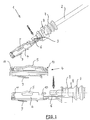
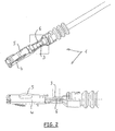
Figuren 1 und2 ist, soweit im Einzelnen dargestellt, mit der Bezugsziffer 1 ein Kontaktpartner für einen Steckverbinder bezeichnet. Ein oder mehrere solche Kontaktpartner 1 werden in ein Steckverbindergehäuse, genauer deren Kontaktkammern, eingesetzt und bilden somit eine einreihige, mehrreihige und somit mehrpolige Steckverbindung. - Der Kontaktpartner 1 ist an dem Ende eines Kabels 2, das einen elektrischen Leiter 3 aufweist, angeordnet. Bei dem Kabel 2 handelt es sich um ein einpoliges Kabel, es kann aber auch als mehrpoliges Kabel (wie z.B. Stegleitung) ausgebildet sein. Es muss sich auch nicht zwangsweise um ein Rundkabel handeln, sondern es kann auch eine Flachbandleitung sein.
- Das Ende des elektrischen Leiters 3 ist an einem Kontaktgehäuse 4 (Halteschutzbuchse) dauerhaft angefügt, wobei weiterhin an dem Kontaktgehäuse 4 eine Druckfeder 5 angeordnet ist, die auf einen hier nicht dargestellten Gegenkontaktpartner zur Erzielung der entsprechenden Kontaktkräfte wirkt.
- Erfindungsgemäß ist das Kontaktgehäuse 4 mit einem zusätzlichen Kontaktteil 6 versehen, welches z.B. nur in dem Bereich, in dem der elektrische Leiter 3 mit dem Kontaktgehäuse 4 verbunden werden soll, vorhanden ist.
- Bei dem in
Figur 1 gezeigten Ausführungsbeispiel erstreckt sich das zusätzliche Kontaktteil 6, ausgehend von dem Bereich, in dem der elektrische Leiter 3 vorhanden ist, bis in Richtung der Steckseite des Kontaktgehäuses 4, wobei in der mittleren Darstellung derFigur 1 erkennbar ist, dass es im steckseitigen Endbereich umgebogen ist. Durch dieses separate Bauteil in Form des Kontaktteiles 6 besteht bei Bedarf gleichzeitig die Möglichkeit, die kontaktteillose Kontaktierung in verschiedenen Oberflächenausführungen (wie z.B. Gold, Silber, Zinn usw.) extrem kostengünstig auszuführen, wobei nur eine einzige Fertigungswerkzeugvariante für das Kontaktgehäuse 4 benötigt wird, da das Kontaktteil 6 in der gewünschten Formgebung und mit dem gewünschten Material zusätzlich eingesetzt werden kann. Hierzu ist es denkbar, dass das Kontaktteil 6 mittels Kraftschluss an dem Kontaktgehäuse 4 festgelegt wird und der elektrische Leiter 3 mittels des schon erwähnten Löt- oder Schweißverfahrens, insbesondere dem Reibschweißverfahren, an dem Kontaktteil 6 angefügt wird. - Wenn der entsprechend der in der
Figur 1 gezeigte Kontaktpartner 1 fertig hergestellt ist und der elektrische Leiter an das Kontaktteil 6 angefügt wurde, wird noch eine Dichtung 7, insbesondere eine so genannte Einzelleiterabdichtung, auf den elektrisch nicht leitfähigen Außenmantel des Kabels 2 aufgeschoben und mittels Crimpflügel 8, die vorzugsweise Bestandteil des Kontaktgehäuses 4 sind, dort mechanisch festgelegt, so dass auch eine Zugentlastung des Kontaktgehäuses 4 von auf das Kabel 2 wirkenden Zug- und Druckkräfte realisiert ist. Ein derart hergestellter und vorbereiteter Kontaktpartner 1 kann dann in eine Kontaktkammer eines hier nicht näher dargestellten Steckverbindergehäuses eingesetzt werden. - In der
Figur 1 ist die Ausführung des Fügeprozesses, mit dem der elektrische Leiter an dem Kontaktteil 6 angefügt wird, noch nicht dargestellt. Durch den punktierten Pfeil ist lediglich dargestellt, dass der elektrische Leiter 3 diesem Fügeprozess unterworfen wird und an dem Kontaktteil 6 angefügt wird. Dabei erfolgt eine Plattierung und damit einhergehend eine Kompaktierung des elektrischen Leiters 3, der hier als Litzenleiter ausgeführt ist. Dies Kompaktierung kann beispielsweise mittels eines Reibschweißverfahrens erzielt werden, so dass die geometrischen Verhältnisse nach Ausführung der Kompaktierung und des Fügens inFigur 2 dargestellt sind. Hier ist erkennbar, dass der elektrische Leiter 3 plattiert worden ist und an dem Kontaktteil 6 dauerhaft und zuverlässig angefügt wurde. - Bei Betrachtung der
Figur 1 , insbesondere die mittlere Darstellung, ist erkennbar, dass die Halteschutzbuchse 4, die Druckfeder 5 und das Kontaktteil 6 voneinander separate Teile sind, die auch in voneinander separaten Herstellungsschritten bzw.
Herstellungsverfahren hergestellt werden können. Dabei können gleichartige oder voneinander unterschiedliche Materialien zum Einsatz kommen. Bevorzugt werden solche Herstellungsverfahren und solche Materialien, die für den jeweiligen Zweck optimal sind. So wird vorzugsweise das Kontaktgehäuse 4 aus einem dünnen und preiswerten Blechstreifen in einem Stanzbiegeverfahren aus einem elektrisch leitfähigen Material hergestellt. Die Druckfeder 5 wird aus einem Material hergestellt, welches Federeigenschaften (wie z.B. ein Federstahl) aufweist, um dauerhaft die erforderlichen Kontaktkräfte aufbringen zu können, wenn in das Kontaktgehäuse 4 ein entsprechender Gegenkontakt eingesetzt ist. Das Kontaktteil 6 besteht, wie schon beschrieben, aus einem Material, das einerseits die erforderlichen Kontaktierungseigenschaften zwecks Kontaktierung mit dem eingesetzten Gegenkontakt aufweist und andererseits auf das Fügeverfahren, mit dem der elektrische Leiter 3 an dem Kontaktteil 6 angefügt wird, entspricht. Diese genannten beteiligten Bauelemente des Kontaktpartners 1 werden je nach Anforderungen kraftschlüssig und/oder formschlüssig miteinander verbunden. So ist es bei dem Ausführungsbeispiel, welches in den Figuren gezeigt ist, so ausgeführt, dass das Kontaktteil 6 durch Formschluss mittels verformbarer Laschen 10 und eines Steges 11 an dem Kontaktgehäuse 4 festgelegt ist. Dabei sind z.B. mittels der Laschen 10 auch die Druckfeder 5 kraftschlüssig an dem Kontaktgehäuse 4 festgelegt, wobei aber auch ein Formschluss alternativ oder ergänzend zu dem Kraftschluss zur Festlegung der Druckfeder 5 an dem Kontaktgehäuse 4 in Betracht kommt. - Insgesamt bietet die Erfindung also den Vorteil, dass das Kontaktgehäuse 4 schnell und einfach sowie kostengünstig hergestellt werden kann, wobei gleichzeitig auf Grund des erfindungsgemäße zusätzlichen Kontaktteils 6 sichergestellt ist, dass die mechanische Festlegung und elektrische Kontaktierung des elektrischen Leiters 3 an diesem Kontaktteil 6 dauerhaft und zuverlässig ohne Beeinträchtigungen an dem Kontaktgehäuse 4 erfolgen kann, wobei weiterhin durch das zusätzliche Kontaktteil 6 insbesondere dann die hohe Kontaktsicherheit zu einem Gegenkontakt hergestellt ist, wenn sich das Kontaktteil 6 bis in Richtung des in Richtung des in das Kontaktgehäuse 4 eingesetzten Gegenkontaktes erstreckt.
-
- 1.
- Kontaktpartner
- 2.
- Kabel
- 3.
- elektrischer Leiter
- 4.
- Kontaktgehäuse
- 5.
- Druckfeder
- 6.
- Kontaktteil
- 7.
- Dichtung
- 8.
- Crimpflügel
- 9.
- Federlasche
- 10.
- Lasche
- 11.
- Steg
Claims (8)
- Verfahren zur Herstellung eines Kontaktpartners (1) für einen Steckverbinder, wobei eine auf einem Gegenkontaktpartner wirkende Druckfeder (5) an einem Kontaktgehäuse (4), das zur Aufnahme des Gegenkontaktpartners ausgebildet ist, angefügt wird, wobei weiterhin der Kontaktpartner (1) an einem Ende eines Kabels (2) angeordnet ist, und ein elektrischer Leiter (3) des Kabels (2) elektrisch mit dem Kontaktpartner (1) verbunden wird, dadurch gekennzeichnet, dass das Kontaktgehäuse (4) zusätzlich mit einem Kontaktteil (6) versehen wird, an dem der elektrische Leiter (3) an das Kontaktgehäuse (4) angefügt wird, wobei das Kontaktteil (6) zur Durchführung dieses Fügeprozesses ausgebildet ist.
- Verfahren nach Anspruch 1, dadurch gekennzeichnet, dass das Kontaktteil (6) mittels Kraftschluss an dem Kontaktgehäuse (4) festgelegt wird und der elektrische Leiter (3) in einem Löt- oder Schweißverfahren an dem Kontaktteil (6) angefügt wird.
- Verfahren nach Anspruch 2, dadurch gekennzeichnet, dass das Schweißverfahren ein Reibschweißverfahren ist.
- Verfahren nach einem der vorhergehenden Ansprüche, dadurch gekennzeichnet, dass das Kontaktgehäuse (4) und die Druckfeder (5) sowie das Kontaktteil (6) aus gleichen oder unterschiedlichen Materialien in einem Stanzbiegeverfahren als separate Bauteile hergestellt und danach zusammenmontiert werden.
- Verfahren nach einem der vorhergehenden Ansprüche, dadurch gekennzeichnet, dass das Kontaktteil (6) von der Druckfeder (5) gebildet wird.
- Verfahren nach einem der vorhergehenden Ansprüche, dadurch gekennzeichnet, dass der elektrische Leiter (3) vor und/oder während des Fügens an das Kontaktteil (6) plattiert wird.
- Kontaktpartner (1), hergestellt nach einem Verfahren gemäß den vorhergehenden Patentansprüchen.
- Kontaktpartner (1) nach Anspruch 7, dadurch gekennzeichnet, dass das Kontaktgehäuse 4 zumindest eine Lasche (10) und/oder einen Steg (11) aufweist, mit dem das Kontaktteil (6) kraftschlüssig an dem Kontaktgehäuse (4) festgelegt ist.
Applications Claiming Priority (1)
| Application Number | Priority Date | Filing Date | Title |
|---|---|---|---|
| DE102007051710 | 2007-10-30 |
Publications (3)
| Publication Number | Publication Date |
|---|---|
| EP2065981A2 true EP2065981A2 (de) | 2009-06-03 |
| EP2065981A3 EP2065981A3 (de) | 2012-03-07 |
| EP2065981B1 EP2065981B1 (de) | 2017-03-22 |
Family
ID=40560998
Family Applications (1)
| Application Number | Title | Priority Date | Filing Date |
|---|---|---|---|
| EP08018944.2A Not-in-force EP2065981B1 (de) | 2007-10-30 | 2008-10-30 | Verfahren zur Herstellung einer Halteschutzbuchse für eine kontaktteillose Steckverbindung |
Country Status (3)
| Country | Link |
|---|---|
| EP (1) | EP2065981B1 (de) |
| DE (1) | DE102008053882A1 (de) |
| ES (1) | ES2627662T3 (de) |
Citations (1)
| Publication number | Priority date | Publication date | Assignee | Title |
|---|---|---|---|---|
| DE102006014156A1 (de) | 2006-03-24 | 2007-09-27 | Hirschmann Automotive Gmbh | Halteschutzbuchse für ein kontaktteilloses Stecksystem |
Family Cites Families (2)
| Publication number | Priority date | Publication date | Assignee | Title |
|---|---|---|---|---|
| EP0018863A1 (de) * | 1979-05-07 | 1980-11-12 | The Bendix Corporation | Elektrische Anschlussklemme zur Herstellung einer Pressverbindung für Aluminiumdraht |
| JP4381872B2 (ja) * | 2004-04-09 | 2009-12-09 | 矢崎総業株式会社 | 電線圧着方法 |
-
2008
- 2008-10-30 EP EP08018944.2A patent/EP2065981B1/de not_active Not-in-force
- 2008-10-30 DE DE102008053882A patent/DE102008053882A1/de not_active Withdrawn
- 2008-10-30 ES ES08018944.2T patent/ES2627662T3/es active Active
Patent Citations (1)
| Publication number | Priority date | Publication date | Assignee | Title |
|---|---|---|---|---|
| DE102006014156A1 (de) | 2006-03-24 | 2007-09-27 | Hirschmann Automotive Gmbh | Halteschutzbuchse für ein kontaktteilloses Stecksystem |
Also Published As
| Publication number | Publication date |
|---|---|
| ES2627662T3 (es) | 2017-07-31 |
| DE102008053882A1 (de) | 2009-05-20 |
| EP2065981B1 (de) | 2017-03-22 |
| EP2065981A3 (de) | 2012-03-07 |
Similar Documents
| Publication | Publication Date | Title |
|---|---|---|
| DE102005016235B4 (de) | Draht-Pressklemmverfahren und Anschlussklemmen-Draht-Verbindung | |
| EP3602690B1 (de) | Verbindung eines anschlussteils mit einer litzenleitung | |
| EP2362491B1 (de) | Verfahren zum Verbinden einer elektrischen Leitung mit einem elektrischen Anschlusselement | |
| DE112012003277T5 (de) | Pressverfahren für Draht und Draht mit damit hergestelltem Anschluss | |
| DE112012003275T5 (de) | Pressverfahren für Draht und Draht mit damit hergestelltem Anschluss | |
| EP1133013B1 (de) | Kontaktstück für eine elektrische Steckverbindung sowie Verfahren zu dessen Herstellung | |
| DE102005016236A1 (de) | Drahtendbereich-Pressbefestigungsstruktur | |
| DE102011077888A1 (de) | Leitung und Verfahren zur Konfektionierung einer solchen Leitung | |
| EP2131448A1 (de) | Verfahren zum Verbinden eines elektrisch leitenden Bauteils mit einem flexiblen elektrischen Leiter | |
| DE102007055040A1 (de) | Kontaktelement und Verfahren zur Herstellung eines Kontaktelementes | |
| DE102010009284B4 (de) | Leitungseinheit mit Dichtfunktion | |
| EP2245705B1 (de) | Steckverbinderelement mit abdichtung im kabelanschlussbereich | |
| EP2791395A1 (de) | Kontaktelement und verfahren zu seiner herstellung | |
| EP1837955A1 (de) | Halteschutzbuchse für einen Steckverbinder | |
| EP2012392B1 (de) | Verbesserte Halteschutzbuchse eines Steckverbinders | |
| EP2065981B1 (de) | Verfahren zur Herstellung einer Halteschutzbuchse für eine kontaktteillose Steckverbindung | |
| DE8711955U1 (de) | Elektrisches Verbindungselement | |
| DE102011077886B4 (de) | Verfahren zur Leitungskonfektionierung | |
| EP1363362B1 (de) | Umformen von Leiterenden eines Flachbandkabels | |
| WO2016096109A1 (de) | Crimpkontakt und verbindungsanordnung mit einem crimpkontakt | |
| DE102006025661B4 (de) | Kontaktklemme zum Anschließen eines Litzenleiters an einen relativ dünnen Anschlussstift | |
| DE102012216895B3 (de) | Verdrillen von Leitungen mit Vorsteckelement | |
| EP2425492B1 (de) | Elektrische steckvorrichtung | |
| DE102020119741A1 (de) | Kontaktelement und Verfahren zur Herstellung eines Kontaktelements | |
| EP3874562B1 (de) | Klemmfeder für eine schraubenlose anschlussklemme |
Legal Events
| Date | Code | Title | Description |
|---|---|---|---|
| PUAI | Public reference made under article 153(3) epc to a published international application that has entered the european phase |
Free format text: ORIGINAL CODE: 0009012 |
|
| AK | Designated contracting states |
Kind code of ref document: A2 Designated state(s): AT BE BG CH CY CZ DE DK EE ES FI FR GB GR HR HU IE IS IT LI LT LU LV MC MT NL NO PL PT RO SE SI SK TR |
|
| AX | Request for extension of the european patent |
Extension state: AL BA MK RS |
|
| PUAL | Search report despatched |
Free format text: ORIGINAL CODE: 0009013 |
|
| AK | Designated contracting states |
Kind code of ref document: A3 Designated state(s): AT BE BG CH CY CZ DE DK EE ES FI FR GB GR HR HU IE IS IT LI LT LU LV MC MT NL NO PL PT RO SE SI SK TR |
|
| AX | Request for extension of the european patent |
Extension state: AL BA MK RS |
|
| RIC1 | Information provided on ipc code assigned before grant |
Ipc: H01R 13/11 20060101AFI20120203BHEP Ipc: H01R 4/02 20060101ALI20120203BHEP |
|
| AKY | No designation fees paid | ||
| REG | Reference to a national code |
Ref country code: DE Ref legal event code: R108 |
|
| RBV | Designated contracting states (corrected) |
Designated state(s): AT BE BG CH CY CZ LI |
|
| 17P | Request for examination filed |
Effective date: 20120914 |
|
| RBV | Designated contracting states (corrected) |
Designated state(s): AT BE BG CH CY CZ DE DK EE ES FI FR GB GR HR HU IE IS IT LI LT LU LV MC MT NL NO PL PT RO SE SI SK TR |
|
| RAP1 | Party data changed (applicant data changed or rights of an application transferred) |
Owner name: HIRSCHMANN AUTOMOTIVE GMBH Owner name: BAYERISCHE MOTOREN WERKE AKTIENGESELLSCHAFT |
|
| GRAP | Despatch of communication of intention to grant a patent |
Free format text: ORIGINAL CODE: EPIDOSNIGR1 |
|
| INTG | Intention to grant announced |
Effective date: 20161014 |
|
| STAA | Information on the status of an ep patent application or granted ep patent |
Free format text: STATUS: GRANT OF PATENT IS INTENDED |
|
| GRAS | Grant fee paid |
Free format text: ORIGINAL CODE: EPIDOSNIGR3 |
|
| GRAA | (expected) grant |
Free format text: ORIGINAL CODE: 0009210 |
|
| STAA | Information on the status of an ep patent application or granted ep patent |
Free format text: STATUS: THE PATENT HAS BEEN GRANTED |
|
| AK | Designated contracting states |
Kind code of ref document: B1 Designated state(s): AT BE BG CH CY CZ DE DK EE ES FI FR GB GR HR HU IE IS IT LI LT LU LV MC MT NL NO PL PT RO SE SI SK TR |
|
| REG | Reference to a national code |
Ref country code: GB Ref legal event code: FG4D Free format text: NOT ENGLISH |
|
| REG | Reference to a national code |
Ref country code: RO Ref legal event code: EPE |
|
| REG | Reference to a national code |
Ref country code: CH Ref legal event code: EP |
|
| REG | Reference to a national code |
Ref country code: AT Ref legal event code: REF Ref document number: 878594 Country of ref document: AT Kind code of ref document: T Effective date: 20170415 |
|
| REG | Reference to a national code |
Ref country code: IE Ref legal event code: FG4D Free format text: LANGUAGE OF EP DOCUMENT: GERMAN |
|
| REG | Reference to a national code |
Ref country code: DE Ref legal event code: R096 Ref document number: 502008015134 Country of ref document: DE |
|
| REG | Reference to a national code |
Ref country code: NL Ref legal event code: MP Effective date: 20170322 |
|
| PG25 | Lapsed in a contracting state [announced via postgrant information from national office to epo] |
Ref country code: LT Free format text: LAPSE BECAUSE OF FAILURE TO SUBMIT A TRANSLATION OF THE DESCRIPTION OR TO PAY THE FEE WITHIN THE PRESCRIBED TIME-LIMIT Effective date: 20170322 Ref country code: FI Free format text: LAPSE BECAUSE OF FAILURE TO SUBMIT A TRANSLATION OF THE DESCRIPTION OR TO PAY THE FEE WITHIN THE PRESCRIBED TIME-LIMIT Effective date: 20170322 Ref country code: NO Free format text: LAPSE BECAUSE OF FAILURE TO SUBMIT A TRANSLATION OF THE DESCRIPTION OR TO PAY THE FEE WITHIN THE PRESCRIBED TIME-LIMIT Effective date: 20170622 Ref country code: GR Free format text: LAPSE BECAUSE OF FAILURE TO SUBMIT A TRANSLATION OF THE DESCRIPTION OR TO PAY THE FEE WITHIN THE PRESCRIBED TIME-LIMIT Effective date: 20170623 Ref country code: HR Free format text: LAPSE BECAUSE OF FAILURE TO SUBMIT A TRANSLATION OF THE DESCRIPTION OR TO PAY THE FEE WITHIN THE PRESCRIBED TIME-LIMIT Effective date: 20170322 |
|
| REG | Reference to a national code |
Ref country code: ES Ref legal event code: FG2A Ref document number: 2627662 Country of ref document: ES Kind code of ref document: T3 Effective date: 20170731 |
|
| REG | Reference to a national code |
Ref country code: LT Ref legal event code: MG4D |
|
| PG25 | Lapsed in a contracting state [announced via postgrant information from national office to epo] |
Ref country code: LV Free format text: LAPSE BECAUSE OF FAILURE TO SUBMIT A TRANSLATION OF THE DESCRIPTION OR TO PAY THE FEE WITHIN THE PRESCRIBED TIME-LIMIT Effective date: 20170322 Ref country code: SE Free format text: LAPSE BECAUSE OF FAILURE TO SUBMIT A TRANSLATION OF THE DESCRIPTION OR TO PAY THE FEE WITHIN THE PRESCRIBED TIME-LIMIT Effective date: 20170322 Ref country code: BG Free format text: LAPSE BECAUSE OF FAILURE TO SUBMIT A TRANSLATION OF THE DESCRIPTION OR TO PAY THE FEE WITHIN THE PRESCRIBED TIME-LIMIT Effective date: 20170622 |
|
| PG25 | Lapsed in a contracting state [announced via postgrant information from national office to epo] |
Ref country code: NL Free format text: LAPSE BECAUSE OF FAILURE TO SUBMIT A TRANSLATION OF THE DESCRIPTION OR TO PAY THE FEE WITHIN THE PRESCRIBED TIME-LIMIT Effective date: 20170322 |
|
| REG | Reference to a national code |
Ref country code: FR Ref legal event code: PLFP Year of fee payment: 10 |
|
| PG25 | Lapsed in a contracting state [announced via postgrant information from national office to epo] |
Ref country code: SK Free format text: LAPSE BECAUSE OF FAILURE TO SUBMIT A TRANSLATION OF THE DESCRIPTION OR TO PAY THE FEE WITHIN THE PRESCRIBED TIME-LIMIT Effective date: 20170322 Ref country code: EE Free format text: LAPSE BECAUSE OF FAILURE TO SUBMIT A TRANSLATION OF THE DESCRIPTION OR TO PAY THE FEE WITHIN THE PRESCRIBED TIME-LIMIT Effective date: 20170322 |
|
| PG25 | Lapsed in a contracting state [announced via postgrant information from national office to epo] |
Ref country code: PL Free format text: LAPSE BECAUSE OF FAILURE TO SUBMIT A TRANSLATION OF THE DESCRIPTION OR TO PAY THE FEE WITHIN THE PRESCRIBED TIME-LIMIT Effective date: 20170322 Ref country code: IS Free format text: LAPSE BECAUSE OF FAILURE TO SUBMIT A TRANSLATION OF THE DESCRIPTION OR TO PAY THE FEE WITHIN THE PRESCRIBED TIME-LIMIT Effective date: 20170722 Ref country code: PT Free format text: LAPSE BECAUSE OF FAILURE TO SUBMIT A TRANSLATION OF THE DESCRIPTION OR TO PAY THE FEE WITHIN THE PRESCRIBED TIME-LIMIT Effective date: 20170724 |
|
| REG | Reference to a national code |
Ref country code: DE Ref legal event code: R097 Ref document number: 502008015134 Country of ref document: DE |
|
| PLBE | No opposition filed within time limit |
Free format text: ORIGINAL CODE: 0009261 |
|
| STAA | Information on the status of an ep patent application or granted ep patent |
Free format text: STATUS: NO OPPOSITION FILED WITHIN TIME LIMIT |
|
| PG25 | Lapsed in a contracting state [announced via postgrant information from national office to epo] |
Ref country code: DK Free format text: LAPSE BECAUSE OF FAILURE TO SUBMIT A TRANSLATION OF THE DESCRIPTION OR TO PAY THE FEE WITHIN THE PRESCRIBED TIME-LIMIT Effective date: 20170322 |
|
| 26N | No opposition filed |
Effective date: 20180102 |
|
| PG25 | Lapsed in a contracting state [announced via postgrant information from national office to epo] |
Ref country code: SI Free format text: LAPSE BECAUSE OF FAILURE TO SUBMIT A TRANSLATION OF THE DESCRIPTION OR TO PAY THE FEE WITHIN THE PRESCRIBED TIME-LIMIT Effective date: 20170322 |
|
| PG25 | Lapsed in a contracting state [announced via postgrant information from national office to epo] |
Ref country code: MC Free format text: LAPSE BECAUSE OF FAILURE TO SUBMIT A TRANSLATION OF THE DESCRIPTION OR TO PAY THE FEE WITHIN THE PRESCRIBED TIME-LIMIT Effective date: 20170322 |
|
| REG | Reference to a national code |
Ref country code: CH Ref legal event code: PL |
|
| REG | Reference to a national code |
Ref country code: IE Ref legal event code: MM4A |
|
| PG25 | Lapsed in a contracting state [announced via postgrant information from national office to epo] |
Ref country code: CH Free format text: LAPSE BECAUSE OF NON-PAYMENT OF DUE FEES Effective date: 20171031 Ref country code: LU Free format text: LAPSE BECAUSE OF NON-PAYMENT OF DUE FEES Effective date: 20171030 Ref country code: LI Free format text: LAPSE BECAUSE OF NON-PAYMENT OF DUE FEES Effective date: 20171031 |
|
| REG | Reference to a national code |
Ref country code: BE Ref legal event code: MM Effective date: 20171031 |
|
| PG25 | Lapsed in a contracting state [announced via postgrant information from national office to epo] |
Ref country code: BE Free format text: LAPSE BECAUSE OF NON-PAYMENT OF DUE FEES Effective date: 20171031 |
|
| PG25 | Lapsed in a contracting state [announced via postgrant information from national office to epo] |
Ref country code: MT Free format text: LAPSE BECAUSE OF FAILURE TO SUBMIT A TRANSLATION OF THE DESCRIPTION OR TO PAY THE FEE WITHIN THE PRESCRIBED TIME-LIMIT Effective date: 20170322 |
|
| REG | Reference to a national code |
Ref country code: FR Ref legal event code: PLFP Year of fee payment: 11 |
|
| PG25 | Lapsed in a contracting state [announced via postgrant information from national office to epo] |
Ref country code: IE Free format text: LAPSE BECAUSE OF NON-PAYMENT OF DUE FEES Effective date: 20171030 |
|
| REG | Reference to a national code |
Ref country code: AT Ref legal event code: MM01 Ref document number: 878594 Country of ref document: AT Kind code of ref document: T Effective date: 20171030 |
|
| PG25 | Lapsed in a contracting state [announced via postgrant information from national office to epo] |
Ref country code: AT Free format text: LAPSE BECAUSE OF NON-PAYMENT OF DUE FEES Effective date: 20171030 |
|
| PG25 | Lapsed in a contracting state [announced via postgrant information from national office to epo] |
Ref country code: HU Free format text: LAPSE BECAUSE OF FAILURE TO SUBMIT A TRANSLATION OF THE DESCRIPTION OR TO PAY THE FEE WITHIN THE PRESCRIBED TIME-LIMIT; INVALID AB INITIO Effective date: 20081030 |
|
| PG25 | Lapsed in a contracting state [announced via postgrant information from national office to epo] |
Ref country code: CY Free format text: LAPSE BECAUSE OF NON-PAYMENT OF DUE FEES Effective date: 20170322 |
|
| PG25 | Lapsed in a contracting state [announced via postgrant information from national office to epo] |
Ref country code: TR Free format text: LAPSE BECAUSE OF FAILURE TO SUBMIT A TRANSLATION OF THE DESCRIPTION OR TO PAY THE FEE WITHIN THE PRESCRIBED TIME-LIMIT Effective date: 20170322 |
|
| PGFP | Annual fee paid to national office [announced via postgrant information from national office to epo] |
Ref country code: GB Payment date: 20231020 Year of fee payment: 16 |
|
| PGFP | Annual fee paid to national office [announced via postgrant information from national office to epo] |
Ref country code: ES Payment date: 20231222 Year of fee payment: 16 |
|
| PGFP | Annual fee paid to national office [announced via postgrant information from national office to epo] |
Ref country code: RO Payment date: 20231019 Year of fee payment: 16 Ref country code: IT Payment date: 20231026 Year of fee payment: 16 Ref country code: FR Payment date: 20231024 Year of fee payment: 16 Ref country code: CZ Payment date: 20231023 Year of fee payment: 16 |
|
| GBPC | Gb: european patent ceased through non-payment of renewal fee |
Effective date: 20241030 |
|
| PG25 | Lapsed in a contracting state [announced via postgrant information from national office to epo] |
Ref country code: GB Free format text: LAPSE BECAUSE OF NON-PAYMENT OF DUE FEES Effective date: 20241030 |
|
| PG25 | Lapsed in a contracting state [announced via postgrant information from national office to epo] |
Ref country code: FR Free format text: LAPSE BECAUSE OF NON-PAYMENT OF DUE FEES Effective date: 20241031 |
|
| PG25 | Lapsed in a contracting state [announced via postgrant information from national office to epo] |
Ref country code: RO Free format text: LAPSE BECAUSE OF NON-PAYMENT OF DUE FEES Effective date: 20241030 |
|
| PG25 | Lapsed in a contracting state [announced via postgrant information from national office to epo] |
Ref country code: CZ Free format text: LAPSE BECAUSE OF NON-PAYMENT OF DUE FEES Effective date: 20241030 |
|
| PG25 | Lapsed in a contracting state [announced via postgrant information from national office to epo] |
Ref country code: IT Free format text: LAPSE BECAUSE OF NON-PAYMENT OF DUE FEES Effective date: 20241030 |
|
| REG | Reference to a national code |
Ref country code: ES Ref legal event code: FD2A Effective date: 20251204 |
|
| PGFP | Annual fee paid to national office [announced via postgrant information from national office to epo] |
Ref country code: DE Payment date: 20251021 Year of fee payment: 18 |
|
| PG25 | Lapsed in a contracting state [announced via postgrant information from national office to epo] |
Ref country code: ES Free format text: LAPSE BECAUSE OF NON-PAYMENT OF DUE FEES Effective date: 20241031 |