EP2065674B1 - Shearographischer Messapparat - Google Patents
Shearographischer Messapparat Download PDFInfo
- Publication number
- EP2065674B1 EP2065674B1 EP09002071A EP09002071A EP2065674B1 EP 2065674 B1 EP2065674 B1 EP 2065674B1 EP 09002071 A EP09002071 A EP 09002071A EP 09002071 A EP09002071 A EP 09002071A EP 2065674 B1 EP2065674 B1 EP 2065674B1
- Authority
- EP
- European Patent Office
- Prior art keywords
- tire
- pressure chamber
- images
- image
- shearogram
- Prior art date
- Legal status (The legal status is an assumption and is not a legal conclusion. Google has not performed a legal analysis and makes no representation as to the accuracy of the status listed.)
- Expired - Fee Related
Links
- 238000003384 imaging method Methods 0.000 title description 8
- 238000012360 testing method Methods 0.000 claims description 72
- 238000000034 method Methods 0.000 claims description 33
- 238000007689 inspection Methods 0.000 claims description 17
- 238000010438 heat treatment Methods 0.000 claims description 16
- 230000007246 mechanism Effects 0.000 claims description 11
- 238000004891 communication Methods 0.000 claims description 6
- 238000012935 Averaging Methods 0.000 claims description 3
- 238000012800 visualization Methods 0.000 claims description 2
- 230000000717 retained effect Effects 0.000 claims 9
- 230000007547 defect Effects 0.000 description 24
- 238000007906 compression Methods 0.000 description 18
- 230000006835 compression Effects 0.000 description 17
- 230000008569 process Effects 0.000 description 14
- 230000003287 optical effect Effects 0.000 description 10
- 238000012545 processing Methods 0.000 description 9
- 230000002829 reductive effect Effects 0.000 description 9
- 238000004458 analytical method Methods 0.000 description 8
- 230000003068 static effect Effects 0.000 description 8
- 230000008901 benefit Effects 0.000 description 7
- 230000008859 change Effects 0.000 description 7
- 238000010586 diagram Methods 0.000 description 7
- 239000000463 material Substances 0.000 description 7
- XLYOFNOQVPJJNP-UHFFFAOYSA-N water Substances O XLYOFNOQVPJJNP-UHFFFAOYSA-N 0.000 description 7
- 230000001427 coherent effect Effects 0.000 description 6
- 230000000694 effects Effects 0.000 description 5
- 230000033001 locomotion Effects 0.000 description 5
- 238000010008 shearing Methods 0.000 description 5
- 238000012546 transfer Methods 0.000 description 5
- 239000011324 bead Substances 0.000 description 4
- 230000010354 integration Effects 0.000 description 4
- 239000000725 suspension Substances 0.000 description 4
- 230000015556 catabolic process Effects 0.000 description 3
- 238000006731 degradation reaction Methods 0.000 description 3
- 238000001514 detection method Methods 0.000 description 3
- 238000005305 interferometry Methods 0.000 description 3
- 230000001795 light effect Effects 0.000 description 3
- 230000009467 reduction Effects 0.000 description 3
- 229910021532 Calcite Inorganic materials 0.000 description 2
- 238000001816 cooling Methods 0.000 description 2
- 238000011161 development Methods 0.000 description 2
- 230000018109 developmental process Effects 0.000 description 2
- 238000005516 engineering process Methods 0.000 description 2
- 238000011156 evaluation Methods 0.000 description 2
- 230000007774 longterm Effects 0.000 description 2
- 230000004044 response Effects 0.000 description 2
- 239000011800 void material Substances 0.000 description 2
- 238000013459 approach Methods 0.000 description 1
- 238000013473 artificial intelligence Methods 0.000 description 1
- 238000013528 artificial neural network Methods 0.000 description 1
- 230000004888 barrier function Effects 0.000 description 1
- 230000009286 beneficial effect Effects 0.000 description 1
- 230000015572 biosynthetic process Effects 0.000 description 1
- 239000003086 colorant Substances 0.000 description 1
- 239000013078 crystal Substances 0.000 description 1
- 125000004122 cyclic group Chemical group 0.000 description 1
- 238000013480 data collection Methods 0.000 description 1
- 230000032798 delamination Effects 0.000 description 1
- 230000005670 electromagnetic radiation Effects 0.000 description 1
- 230000006870 function Effects 0.000 description 1
- 238000009499 grossing Methods 0.000 description 1
- 238000005286 illumination Methods 0.000 description 1
- 230000002452 interceptive effect Effects 0.000 description 1
- 238000011835 investigation Methods 0.000 description 1
- 239000004973 liquid crystal related substance Substances 0.000 description 1
- 238000013507 mapping Methods 0.000 description 1
- 238000005259 measurement Methods 0.000 description 1
- 238000009659 non-destructive testing Methods 0.000 description 1
- 238000013021 overheating Methods 0.000 description 1
- 230000036961 partial effect Effects 0.000 description 1
- 238000003909 pattern recognition Methods 0.000 description 1
- 230000000284 resting effect Effects 0.000 description 1
- 238000012552 review Methods 0.000 description 1
- 238000011896 sensitive detection Methods 0.000 description 1
- 238000000926 separation method Methods 0.000 description 1
- 238000010792 warming Methods 0.000 description 1
Images


Classifications
-
- G—PHYSICS
- G01—MEASURING; TESTING
- G01B—MEASURING LENGTH, THICKNESS OR SIMILAR LINEAR DIMENSIONS; MEASURING ANGLES; MEASURING AREAS; MEASURING IRREGULARITIES OF SURFACES OR CONTOURS
- G01B11/00—Measuring arrangements characterised by the use of optical techniques
- G01B11/16—Measuring arrangements characterised by the use of optical techniques for measuring the deformation in a solid, e.g. optical strain gauge
- G01B11/161—Measuring arrangements characterised by the use of optical techniques for measuring the deformation in a solid, e.g. optical strain gauge by interferometric means
- G01B11/162—Measuring arrangements characterised by the use of optical techniques for measuring the deformation in a solid, e.g. optical strain gauge by interferometric means by speckle- or shearing interferometry
-
- G—PHYSICS
- G01—MEASURING; TESTING
- G01B—MEASURING LENGTH, THICKNESS OR SIMILAR LINEAR DIMENSIONS; MEASURING ANGLES; MEASURING AREAS; MEASURING IRREGULARITIES OF SURFACES OR CONTOURS
- G01B9/00—Measuring instruments characterised by the use of optical techniques
- G01B9/02—Interferometers
- G01B9/021—Interferometers using holographic techniques
- G01B9/025—Double exposure technique
-
- G—PHYSICS
- G01—MEASURING; TESTING
- G01M—TESTING STATIC OR DYNAMIC BALANCE OF MACHINES OR STRUCTURES; TESTING OF STRUCTURES OR APPARATUS, NOT OTHERWISE PROVIDED FOR
- G01M17/00—Testing of vehicles
- G01M17/007—Wheeled or endless-tracked vehicles
- G01M17/02—Tyres
- G01M17/027—Tyres using light, e.g. infrared, ultraviolet or holographic techniques
Definitions
- the present invention relates generally to the field of nondestructive testing. Specifically, the present invention relates to the technique of electronic shearography.
- shearography involves the interference of two laterally displaced images of the same object to form an interference image.
- Conventional shearographic methods require that a first interference image (or baseline image) be taken while the object is in an unstressed or first stressed condition, and another interference image be taken while the object is in a second stressed condition.
- Comparison of these two interference images reveals information about the strain concentrations and hence the integrity of the object in a single image called a shearogram.
- shearography has been shown to be useful to detect strain concentrations and hence defects in vehicle tires, especially retread vehicle tires.
- interference images are stored in a computer memory and are compared electronically to produce single static shearograms. Because all the data are processed electronically, the results of the analysis can be viewed in "real time”. "Real time”, as used in the prior art, refers to the ability to view the shearogram nearly instantaneously after the second interference image has been taken.
- the spatial frequency of the interference image produced in shearographic analysis was relatively high requiring the use of high resolution photographic film to record a useful interference image.
- the development disclosed in the Hung patent produces an interference image with a relatively low spatial frequency because the effective angles between the interfering rays are small. Therefore, the interference images can be recorded by a video camera, a video camera normally having much less resolving capability than a high density or high resolution photographic film.
- each point on the actual interference image is generated by the interference of light emanating from a pair of distinct points on the object. Therefore, each pixel of the video camera is illuminated by light reflected from those two points. If the overall illumination remains constant, then any variations in the pixel intensity, in the interference image, will be due only to changes in the phase relationship of the two points of light.
- an initial intensity for each pixel is recorded, as described above. If differential deformations occur in the object, such deformations will cause changes in the subsequent interference image.
- the intensity of a given pixel will change according to change in the phase relationship between the two rays of light, reflected from the two points on the object, which illuminate the pixel.
- the phase differences can be either positive changes, causing the pixel to become brighter or negative changes, causing the pixel to become darker. Whether the pixel becomes brighter or darker depends on the initial phase relationship and the direction of the change of phase. Due to the cyclic nature of phase interferences, as the deformation of the object continually increases, the intensity at a given pixel may pass through a complete cycle. That is, the intensity of the pixel might increase to a maximum (positive) difference, then return to the original intensity, and then continue to a maximum (negative) difference, and so on.
- a single shearogram is derived from two single static interference images taken at two distinct stress levels.
- the single shearogram is then viewed by an operator for analysis if multiple shearograms are taken, the analysis is done one shearogram at a time.
- the operator attendance time required to perform a thorough stress analysis, is substantial.
- a single shearogram may falsely show light features that appear to be defects (referred to as "false positives"). These "false positives" are caused by different reflective characteristics on the surface of the test object and appear as defects when a static shearogram is viewed.
- a shearographic camera for taking interference images of the test object.
- An animation device such as a computer coupled to the shearography camera is adapted to receive the interference images at a rate of at least 15 frames per second while the test object undergoes a sequence of a continuum of varying stress levels.
- the animation device compares the interference images to a base line interference image of the object in the unstressed or near unstressed state by a process of subtracting each interference image from the base line interference image thereby forming a shearogram.
- Each shearogram image is simultaneously displayed on a display unit and stored in a memory device.
- the sequence of shearogram images is recalled and replayed in sequence on the display unit.
- the sequential display of these shearogram images at a rate of at least 15 frames per second, produces a shearographic animation of the shearograms produced during and after stressing of the test object.
- US-patent 6,246,483 B1 discloses an apparatus for shearographic inspections of articles.
- the article to be inspected and a laser shearing interferometer system are arranged in a vacuum chamber.
- the laser shearing interferometer system comprises a laser, a movable mirror, a CCD imaging camera which may be used for shearography and for electronic speckle interferometry, and an interferometer.
- the images generated by the camera are processed and displayed on a monitor.
- the pressure in the vacuum chamber can be varied by a control unit. This allows the user to see on the monitor a real time dynamic image of the state of the article being tested as the pressure is varied.
- US-patent 4,682,892 an apparatus for testing tires by speckle-shearing interferometry is described.
- the tire to be tested and means for generating an interferogram including a camera and a photographic media are arranged in a vacuum chamber.
- a first pair of images is recorded on the photographic media.
- a partial vacuum is generated in the vacuum chamber for applying a stress to the tire, whereupon a second pair of images is recorded on the photographic media.
- the photographic media is developed to form a transparency.
- Similar arrangements having vacuum chambers are disclosed in US-patents 4,702,594 and 5,703,680 , wherein a video camera is used instead of a photographic camera.
- the invention has for its object to provide an improved apparatus for performing shearography on a test object.
- the present invention relates to an apparatus for performing electronic shearography on a test object such as a tire.
- the shearography testing apparatus of the present invention can include a tire handling system which loads a tire and automatically centers it relative to the shearography camera.
- the tire handling system also utilizes a pivotal loading motion that eases the loading of tires and minimizes the required floor space.
- the shearography testing apparatus of the present invention includes a pressure chamber having an air handling system which can reduce the relative humidity in the interior of the pressure chamber during a test cycle. This can prevent the formation of a fog-like condition in the pressure chamber which could substantially reduce the quality of the interference images taken by the shearography camera.
- the apparatus may further archive the animated images created during shearography testing so that they can be reviewed at a later time.
- the animated image data is compressed prior to storage on the archive medium in such a manner to allow for more efficient storage of the test results without significant degradation of the image quality.
- the data can be archived in a more cost efficient manner without sacrificing any loss of accuracy in the test results.
- the present invention utilizes basic concepts of electronic shearography. More details of electronic shearography are given in U.S. Patent No. 4,887,899 .
- FIG. 1 a schematic block diagram of an arrangement for practicing electronic shearography is depicted.
- Coherent electromagnetic radiation or coherent light is produced by a laser 10, the laser light being directed through a fiberoptic cable 15 (or alternatively directed by a mirror or a set of mirrors or provided directly) to a beam expander or illuminator 20.
- Beam expander 20 directs the coherent light onto a test object 25.
- the surface of test object 25 is illuminated and reflects light into a shearography camera 30.
- Shearography camera 30 includes an optical element 35, a lens 40 for focusing the light, and a detector 45.
- Optical element 35 may be a birefringent material and a polarizer, the birefringent material being a calcite material such as a wolleston prism.
- the optical element is however not limited to a birefringent material and a polarizer, other elements such as a defraction grating, a Michelson mirror, or an appropriate wave plate may be applied. Further, optical element 35 may contain other optics, such as, but not limited to a quarter-wave plate.
- Detector 45 may be a traditional video camera, a digital video camera, a charge coupled device (CCD), or other photo sensitive detection equipment.
- Computer 50 includes a video capture circuit 55, a central processing unit 60, and a memory 65.
- computer 50 may include a logical extractor that is configured to extract shearographic images from memory in a predetermined manner.
- the logical extractor may be embodied in hardware or alternatively in software within computer 50.
- Video capture circuit 55 may be a dedicated video card or a frame grabber preferably capable of capturing entire video images at a rate of at least 15 frames per second. However, video capture circuit 55 may be capable of capturing video images at any suitable rate.
- Central processing unit 60 may be any of a number of conventional microprocessors or a dedicated microprocessor device.
- Detector 45 is coupled to central processing unit 60, central processing unit 60 being coupled to video capture circuit 55 and memory device 65.
- Central processing unit 60 is further coupled to a display unit 70, which may be a CRT (cathode ray tube) display, an LCD (liquid crystal display), or the like.
- coherent light emanating from beam expander 20 is reflected from test object 25.
- Optical element 35 collects the reflected light from object 25 causing an interference image to be created.
- the interference image is focused on detector 45 through lens 40.
- a first interference image is taken while test object 25 is in a first stressed condition, and a second interference image is taken with object 25 in a second stressed condition.
- the two interference images are then compared by a process of differencing one image with respect to the other and the shearogram is created and displayed on a monitor.
- Test object 25 undergoes a sequence of or continuum of varying stress levels.
- Detector 45 continuously captures the interference image from optical element 35 and communicates the interference image to computer 50, during the stress cycle.
- Capture circuit 55 electronically captures entire interference images at a rate of at least 15 frames per second.
- Capture circuit 55 communicates the interference images to central processing unit 60.
- Central processing unit 60 compares the interference image to a baseline interference image of the object in the unstressed or near unstressed state (or alternatively any chosen stress state), by a process of differencing one interference image from the baseline interference image, thereby forming a shearogram. Each shearogram image is simultaneously displayed on display unit 70 and stored in memory device 65.
- microprocessor 60 recalls the sequence of shearogram images captured by capture circuit 55 and replays them in sequence on display unit 70.
- the sequential display of these shearogram images at a rate of at least 15 frames per second, produces a shearographic animation of the shearograms produced during or after stressing of test object 25.
- Test object 25 may be a relatively large object, such as a tire 200, as depicted in FIG. 2 .
- a shearographic camera 230 that is rotatable within the inside of the bead 202 of tire 200 is depicted in FIG. 2 .
- tire 200 may be rotated and camera 230 may be stationary.
- Shearographic camera 230 includes a laser 235 producing a coherent beam of light to illuminate the inside of tire 200.
- Shearographic camera 235 is further coupled to a computer 240 having a display 245, computer 240 and display 245 being used for data acquisition and animation of the resultant shearographic images.
- shearographic imaging camera 230 When used for detection of defects in tires or retread tires, shearographic imaging camera 230 may be positioned inside the tire depicted as position A in FIG. 3 or outside the tire as depicted in FIG. 3 by position B. Having shearographic camera 230 in position A allows for detection of defects in the tread area of tire 200. Having shearographic camera 230 in position B provides for examination of the bead area and side wall area of tire 200.
- shearographic camera 230 and tire 200 may be placed into a vacuum chamber capable of subjecting tire 200 to a vacuum producing stresses on tire 200 by producing a positive pressure (relative to the pressure inside the vacuum.chamber) in voids within tire 200 causing a bulge 250.
- the bulge may be caused by a defect 260, defect 260 possibly being but not limited to a delamination between two layers of the tire or a void in the molded material.
- bulge 250 appears because of positive pressure within the void space of bond 260.
- the graph of FIG. 4 depicts the slope of bulge 250 by line 270.
- Fringe patterns 280 and 290 of a shearogram image is produced by computer 240 (by the method of differencing or by any other image resolving technique) appear as a set of roughly concentric, substantially circular fringe lines corresponding to slope 270 of bulge 250.
- Fringe patterns 280 and 290 are a contour mapping of the absolute value of slope 270 of bulge 250. Therefore, because bulge 250 is substantially symmetric, fringe patterns 280 and 290 appear to be mirror images of each other.
- shearographic camera 230 takes a series of interference images that are communicated to computer 240 while tire 200 undergoes varying vacuum or stress cycle.
- tire 200 undergoes a depressurization cycle and then a pressurization cycle to return the tire to an unstressed state.
- a tire must be sectioned into a number of sectors ranging from four to twelve, or more.
- tire 200 is sectioned into nine different sectors.
- Shearographic camera 230 therefore views an area corresponding to 40° of arc of tire 200.
- Computer 240 continues to collect data and may, in a preferred embodiment, simultaneously display data on display 245 throughout the entirety of the nine sector cycle.
- the shearograms are generated and displayed at a rate such that they appear to be animated.
- FIG. 5 a display 300 is depicted, the display being divided into nine different sectors, each sector 310 corresponding to an approximate 40° arc of the inside of a tire. Alternatively, however, each sector 310 could correspond to any specific field of view, of a tire, for a shearographic camera, such as shearographic camera 230.
- Computer 240 as depicted in FIG. 2 which maybe connected to display 300, is capable of displaying a plurality of animations simultaneously as depicted in FIG. 5.
- FIG. 5 depicts a static screen shot of a typical display, however, display 300 actually shows animations or sequential imaging of shearogram images produced by computer 240 at a rate providing an animated effect and in a preferred embodiment at a rate of 30 frames per second.
- a display having multiple animation windows or screen sectors provides the clear advantage that an operator may observe the animations simultaneously looking for the appearance of indications of deformations due to defects. This simultaneous observation permits less attendance time by an operator, therefore providing substantial time savings without substantial loss of accuracy. Capturing and providing animation preferably at 30 frames per second (or alternatively any suitable animation rate) provides animations that are sufficiently smooth to be useful to an operator.
- animation improves accuracy in the detection of defects.
- Light effects that would appear as “false positives” in a static shearogram are not manifested as defects when animated, due to the absence of apparent motion induced by the animation.
- a fringe pattern caused by a real defect will tend to "grow” or “shrink” and the intensity of fringe lines will appear to cycle during the animation, due to the continually changing stress state on the test object.
- real defects that may be "washed out” in a static shearogram or even in an integration of multiple shearographic images become apparent with animation of the shearographic images.
- Animation of the shearographic images allows visualization of defects at a multiplicity of stress states, some of the stress states may not cause the "washed out” effect and further the apparent motion created by animation of the images manifests a real defect as opposed to the light effect. Animation of the shearograms goes through a substantial continuity of stress states, therefore defects that may not be present at two chosen stress states become apparent in the animation. These advantages in animation of the shearographic images provide better accuracy in detecting defects and provides for shorter analysis times by an operator.
- animation of shearographic images may be preferable at a rate of at least 15 frames per second, it should be noted that frame rates of less than 15 frames per second may also be used effectively, however the animation may appear discretized as compared to an animation running at least 15 frames per second. Further, it should be appreciated that frame rates of more than 30 frames per second may be advantageous in specific applications and may become simpler to implement as microprocessor and video capture technology is improved.
- Continuous integration describes the process of taking a first interference image and differencing a second interference image to produce a first shearogram.
- a third interference image is taken and subtracted from the first shearogram to produce a second shearogram.
- a fourth interference image is then taken and subtracted from the second shearogram to produce a third shearogram. This sequence is continued throughout the testing cycle.
- the continuous integration technique and other techniques known to those of ordinary skill in the art lend themselves to the animation techniques disclosed above and can be applied thereto.
- the shearogram image data collected can be archived, to allow the same tire image data used by the operator to evaluate the tire during the shearography testing to be reviewed at a later date.
- the capability of archiving the image data can provide several advantages including permitting a decision with respect to the presence of defects in a certain tire to be re-evaluated at a later date such as during the investigation of a potential warranty issue. Additionally, the archived tire data can be used to evaluate the condition of a particular tire over time when the tire is tested multiple times.
- the advantages associated with animating the sequence of images during the original evaluation of the tire are equally applicable to the review of the archived image data.
- the archived data should be substantially the same as the data that was reviewed during the original evaluation.
- the animation of the images preferably should be part of the archived record.
- the raw data collected for each tire can comprise about 250 MB of information in the form of animated pictures which can substantially limit the number of test results that can be stored on a given storage medium.
- the archiving feature can be adapted such that prior to storage, the data is compressed so as to allow for more efficient storage of the test results.
- all of the shearogram image data that is produced is stored in the shear computer's memory such as in the computer's RAM. As explained above, this data can be displayed in the form of animations to allow analysis of the test object for possible defects by an operator.
- This data also can be transferred to an archive memory, for example a hard disk, a CD-ROM or a magnetic tape, where the data can be stored on a long-term basis.
- an archive memory for example a hard disk, a CD-ROM or a magnetic tape
- the data Prior to such long-term storage, the data is compressed so that a substantially larger number of test results can be stored on a given storage medium. Thus, the cost of storing data and the cost of calling up the stored data is reduced.
- the data is compressed in such a manner that the test results can be stored efficiently without significant degradation in the image quality thereby allowing the test results to be reviewed at a later time without any loss of accuracy in detecting defects.
- an archiving computer 340 is provided which is in communication with the shear computer via a parallel cable or the like as shown, for example, in FIG. 6 .
- the software in the shear computer such as for example the boot software and the hardware support software, is modified to support transfer of data to the archive computer.
- the archiving process can be initiated.
- a flow chart illustrating an exemplary set of steps to be performed in the archiving process is shown in FIG. 7 and described below. As will be appreciated, these steps do not have to be performed in the sequence illustrated.
- the individual steps can be performed by the shearography computer 240, the archive computer 340 or any other suitable processor.
- the memory in which the data is archived can be any suitable memory in which data can be stored including, for example, the hard disk drive of the shearography computer, archive computer or other computer, a floppy disk loaded into an external floppy disk drive associated with the shearography computer, archive computer or other computer, a CD-ROM loaded into a CD-ROM drive associated with the shearography computer, archive computer or other computer or a magnetic tape loaded into a tape drive associated with the shearography computer, archive computer or other computer.
- a unique identifier can be entered once all of the data is collected by the shear computer 240. In the exemplary embodiment, this is accomplished by switching the display screen to an operator interface which is run by the archiving computer 340. Through the interface, the operator is prompted to enter a unique identifier for the tire which was tested. To ensure that a unique identifier is entered by the operator, the interface program can be adapted such that the test results collected for a tire will not be displayed until the identifier is entered. In other words, the operator interface will remain on the display until an appropriate identifier is entered for the tire. Once a tire identifier has been entered, the display can be switched back to the shear computer to display the animated shearogram images from the just completed test cycle.
- the tire identifier can be entered via any suitable input device including for example a keyboard or a bar code reader.
- the operator interface program can also allow for the entry of other information regarding the tire such as for example a customer identification or notes.
- the entry of the other information can be made optional such that entry of the tire identifier is the only operator step necessary to implement the data archiving process.
- the operator interface can also display other information regarding the archiving process such as for example, a list of archived files and a status of the amount of storage capacity used.
- an initial compression sequence can be performed, in this case, by the shear computer 240.
- the individual images of the animation sequence that are to be transferred to the archive computer 340 can be reduced in size.
- the image bitmaps stored in the shear computer are 512 pixels wide, 480 pixels tall and have eight bits per pixel.
- Each image bitmap to be transferred to the archive computer 340 can be reduced in size 9:1 to 172 pixels wide and 160 pixels tall using the data from every third column and every third row of the bitmap.
- a pixel averaging technique can be used to reduce the size of the image.
- a single pixel is created that it is the average of the original pixel and the eight pixels which surrounded the original pixel in the original image.
- the average of the original pixel and the five surrounding pixels is used. This has the effect of smoothing the data, reducing noise in the image.
- a header is added to the image to instruct an image viewer how to display the image.
- the shear computer 240 sends a message to the archiving computer 340 containing a file name for the image data.
- the message can also include a scale for creating a grid on the crown view within the archived data associated with the tire.
- the archiving computer 340 then responds to the shear computer 240 with the same file name originally sent by the shear computer. This response signals the shear computer 240 to transfer the files containing the reduced images. The transfer process does not begin until the archiving computer 340 sends the appropriate file name response. As each file is transferred, it is stored in the working directory created by the archiving computer 340. The reduced images can be transferred to the archiving computer in a ".BMP" format.
- the archiving computer After all of the image files have been transferred to the archiving computer 340, the archiving computer further compresses the data. This can be done by converting the image sets for each of the tire sections into an animated graphics file, for example, a GIF file.
- the standard GIF compression includes a built-in transparency feature which allows one of the colors to be made transparent.
- the transparent color is used when a pixel in a frame of the animation is the same as in the preceding frame.
- the first frame of the animated GIF file has the full image data.
- the succeeding frames may use the transparency bit which tells the display program to not change the color of the pixel being displayed. This significantly increases the compression ratio by creating more repeating patterns. Additional details regarding GIF files and compression can be found in the Graphic Interchange Form Programming Reference published by CompuServe Inc. and dated July 31, 1990 .
- the compression provided by the standard GIF compression can be further enhanced by modifying the transparency feature so as to produce a lossy compression.
- a shearography animation it can be difficult to discern between pixel values which change only a relatively small amount in intensity from one frame to the next.
- these pixels can be assigned the transparent color without any substantial degradation of the animation quality.
- the pixel being displayed is constantly being compared to the pixel which is to replace it in the succeeding frame so that transparent pixels can be generated.
- the generation of the transparent pixels is altered by assigning the transparent color to pixels in a frame of the animation which have not changed by more than a predetermined level from the preceding frame as opposed to only those pixels that are identical.
- transparent pixels are much more likely to be generated.
- GIF compression utilizes the LZW compression technique which creates "tokens" that represent longer repeating sequences of bytes. These tokens are created as the compression is taking place.
- the use of a tolerance with regard to the generation of the transparent pixels increases the likelihood of longer strings in the tokens, thereby providing greater compression.
- the decoder program for the animations simply skips past the pixels which have the transparent value, leaving the same color displayed.
- the trigger for assigning a transparent pixel can be set where the brightness level has not changed by more than 8 counts from the displayed brightness.
- the transparent pixel value e.g., 252
- the transparent pixel value would be assigned to that pixel in the second frame.
- the transparent pixel value would not be assigned so that the new pixel value of 24 would be saved and later displayed.
- the compression algorithm of the present invention could, for example, utilize any brightness level of 16 or less as the trigger for assigning the transparent pixel value during the compression.
- a trigger should be selected that reflects a change that is not discernable by the human eye.
- the compression algorithm is not limited to any particular trigger value for assigning the transparent pixel value, but instead can encompass any value which represents a change in the image which is difficult for the human eye to discern.
- a series of animated GIF files each of the which can correspond to a particular section of the tire being tested (or other test object) are saved to the archive storage medium in a directory or subdirectory corresponding to the particular file name.
- an HTML document is created which allows the GIF files to be displayed in any internet browser.
- the HTML document also can contain the tire identifier, the customer name, any notes entered by the operator, the date and time.
- This HTML document can also be saved using the file name and be placed with the GIF files on the archive storage medium.
- An index HTML document is also updated with the file name, tire identifier and any other desired information so as to allow searches for the test results to be performed. For example, a search function could be provided through the operator interface.
- the shearography testing apparatus 410 includes a vacuum chamber 412 into which a tire can be loaded and subjected to a vacuum test cycle (i.e., depressurization and pressurization).
- the vacuum chamber 412 has a generally cylindrical configuration which is divided into upper and lower portions 414, 416.
- the upper and lower portions 414, 416 are pivotally connected together along a rear portion 418 of the vacuum chamber 410 such that, in this instance, the upper portion 414 is movable relative to the lower portion 416 between open and closed positions.
- the separation of the vacuum chamber 412 into the upper and lower portions 414, 416 is along an angle relative to the base 421 of the vacuum chamber.
- the vacuum chamber 412 is divided into the upper and lower portions 414, 416 along a plane that angles downwardly as it extends from the rear 418 to the front 420 of the vacuum chamber. Accordingly, when the upper portion 414 is in the open position, the upper and lower portions 414, 416 define an open mouth having a relatively low front lip 422. This low front lip 422 facilitates the loading and unloading of tires as described below.
- a shearography camera assembly For taking interference images of the tire during the vacuum cycle, a shearography camera assembly is provided.
- the camera assembly which is schematically shown in FIG. 2 , includes a shearographic camera 230 and a laser 235 for illuminating the tire with a coherent beam of light.
- the shearographic camera 230 is supported on a mast 233 that is arranged in centered relation relative to the vacuum chamber 412.
- the mast 233 is extendable along the center axis of the vacuum chamber 412 to allow the camera 230 to be positioned in the interior of the tire for examining the tread area and outside the tire for examining the bead and side wall of the tire.
- the mast 233 is rotatable so that the camera 230 can be positioned to view the different sections or sectors of the tire. As described above, after each vacuum cycle, the camera 230 is rotated to view the next tire sector and the vacuum cycle is repeated.
- the illustrated shearography testing apparatus 410 further includes a tire handling system which loads a tire into the vacuum chamber 412 and automatically centers the tire relative to the chamber and, in turn, the shearography camera.
- the tire handling system provides a simple mechanical centering mechanism which reliably and accurately centers tires of different diameter without the need for any adjustments by an operator.
- the tire handling system utilizes a pivotal loading assembly 424 that minimizes the floor space requirements for the loading/unloading operation and substantially eases the loading/unloading process by allowing a tire to be loaded and unloaded in a substantially vertical position.
- the pivotal loading assembly 424 includes a tire support plate 426 that is movable between a loading position and an inspection position when the vacuum chamber 412 is in the open position.
- the tire support plate 426 In the loading position, the tire support plate 426 is arranged in substantially outside and in front of the vacuum chamber 412. Additionally, the tire support plate 426 extends at a slight angle from vertical toward the rear 418 of the vacuum chamber 412 with a lower end 446 of the support plate being arranged generally in front of the lower front lip 422 of the vacuum chamber mouth as shown in FIGS. 8-10 .
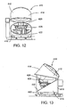
- the tire support plate 426 In the inspection position, the tire support plate 426 is arranged horizontally inside the vacuum chamber 412 and centered relative to the chamber (and, in turn, the shearography camera) as shown in FIGS. 11-13 .
- the support plate 426 is configured such that its center portion is substantially open so that, when the plate is in the inspection position, the camera can view the bottom bead of the tire supported thereon without the need for any additional tire handling.
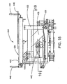
- FIGS. 14-19 An exemplary embodiment of a tire handling system is shown in greater detail in FIGS. 14-19 .
- the tire support plate 426 is mounted on a carriage 428 that is, in turn, connected to a pivot frame 430 via a pair of arms 432 as shown in FIGS. 16-18 .
- the carriage 428 (see, e.g., FIGS. 14 and 15 ) comprises a pair of parallel support members 434 which are interconnected by a pair of laterally extending braces 436 which extend between the support members adjacent the ends thereof When the support plate 426 is in the loading position, the support members 434 are angled slightly rearward from a vertically upstanding position as shown in FIGS. 8 and 10 .
- the support members 434 are horizontal and extend in front-to-back relation to the vacuum chamber 412 when the support plate 426 is in the inspection position.
- Each arm 432 is connected to a respective one of the support members 434 and connects the carriage to a shaft 438 ( FIGS. 15 , 16 and 19 ) which is rotatably supported by the pivot frame 430 and defines the pivot around which the arms 432 and carriage 428 rotate.
- the shaft 438 extends laterally between a pair of legs 440 arranged adjacent a front end of the pivot frame 430 as shown in FIG. 19 .
- the pivotal loading assembly 424 also includes a linear actuator 442 which is pivotally connected at one end to the pivot frame 430 and at the opposing end to one of the arms 432 (see, e.g., FIGS. 17 and 19 ).
- a linear actuator 442 which is pivotally connected at one end to the pivot frame 430 and at the opposing end to one of the arms 432 (see, e.g., FIGS. 17 and 19 ).
- extension and retraction of the linear actuator 442 rotates the shaft 438 and arms 432 relative to the pivot frame 430 and thereby pivots the carriage 428 and support plate 426 between the loading and inspection positions.
- the low front lip 422 of the vacuum chamber 412 facilitates the pivotal movement of the carriage 428 and support plate 426 by presenting a barrier of minimal height that the carriage and support plate must clear.
- the carriage 428 and support plate 426 are substantially vertical when in the loading position, they consume a relatively small amount of floor space particularly as compared to horizontal conveyor type loading systems. The required floor space is also minimized by the fact that the tire is loaded into and unloaded from the vacuum chamber 412 in the same position.
- the support plate 426 For supporting a tire as it is loaded onto the plate, the support plate 426 includes a pair of laterally spaced posts 444.
- the posts 444 are arranged adjacent the lower end 446 of the support plate 426 and are spaced apart a sufficient distance to support tires of different diameter. Since the support plate 426 is arranged substantially vertically in the loading position and the posts 444 are at the lower end 446 of the plate, a tire only has to be lifted a short distance to be loaded onto the support plate.
- the tire handling system automatically centers the tire relative to the vacuum chamber 412 and thereby, the shearography camera by taking advantage of the circular configuration of the tire.
- the posts 444 on the support plate 426 can act as the centering mechanism.
- the posts 444 are arranged on the support plate 426 such that, when the plate is in the inspection position, the posts 444 are positioned on either side of and spaced equidistant from the center of the pressure chamber 412. Accordingly, no matter what diameter tire is placed on the posts 44, it will be centered laterally relative to the chamber and camera when the support plate 426 is pivoted into the inspection position.
- the sensing arm 448 is arranged adjacent an upper end 450 of the carriage 428 in lateral alignment with one of the tire support posts 444. Moreover, the sensing arm 448 and posts 444 are spaced equidistant from the center of the carriage 428.
- the sensing arm 448 is slidable longitudinally along the carriage 428 on a rail 452 ( FIG. 14 ) provided on one of the support members 434.
- the support plate 426 is slidable longitudinally along the carriage 428 on corresponding rails 454 ( FIG. 15 ) provided on the support members 434.
- the support plate 426 and sensing arm 448 are driven along the carriage 428 via, in this case, a screw drive mechanism.
- the lead screw 458 of the drive mechanism extends longitudinally relative to the carriage 428 parallel to the rails and is supported at either end of the carriage by suitable bearings as shown in FIG. 14 .
- a motor 460 is arranged at the upper end of the carriage 428 for rotating the lead screw 458.
- the support plate 426 is coupled via a nut to a lower portion 463 of the lead screw 458 while the sensing arm 448 is coupled via a nut to an upper portion 465 of the lead screw.
- the lower and upper portions 463, 465 of the lead screw 458 are threaded identically, but in opposing directions. Thus, rotation of the lead screw 458 moves the support plate 426 and the sensing arm 448 in opposite directions at the same speed.
- the motor 460 turns the lead screw 458 such that the tire support plate 426 moves towards the upper end of the carriage 428 while the sensing arm 448 moves toward the lower end so that a tire resting on the support posts 444 ends up clamped between the support posts and the sensing arm.
- the sensing arm 448 is pivotally supported such that when the sensing arm contacts the outer surface of the tire, it is pushed past a centered position. This pivotal movement of the sensing arm 448 trips a limit switch that shuts off the screw drive motor 460.
- the tire is in centered position relative to the carriage when the sensing arm 448 contacts the tire.
- the carriage 428 by configuring the carriage 428 such that it is centered relative to the vacuum chamber 414 when the carriage pivots into the inspection position, the tire is also centered relative to the camera.
- the centering sequence can take place at any time prior to the start of the inspection cycle.
- the centering sequence can occur at the same time the carriage is pivoting from the loading to the inspection position.
- the centering sequence can also occur either before or after the carriage is pivoted.
- the illustrated shearography testing apparatus 410 includes an air handling system 446.
- the air handling system 446 includes, in this case, a vacuum pump 468 which draws air through an outlet 470 in the wall of the vacuum chamber 412 as shown in FIG. 20 .
- An inlet valve 472 is also provided in the wall of the vacuum chamber 412. During the depressurization portion of the vacuum cycle, the inlet valve 472 is closed and the vacuum pump 468 draws air out of the vacuum chamber 412. When the vacuum chamber 412 is closed, this reduces the pressure in the vacuum chamber and stresses the tire. While the tire is stressed, the shearographic camera 230 takes a series of interference images of the tire.
- the pressurization portion of the vacuum cycle begins.
- the vacuum pump 468 continues to operate, but the inlet valve 472 is open.
- air is circulated through the closed vacuum chamber 412 through the air inlet and outlet. This returns the vacuum chamber to a normal atmospheric pressure and returns the tire to an unstressed state.
- the camera 230 can then be rotated to the next tire sector and the vacuum cycle repeated.
- the air between the test object and the shearography camera should have a uniform and consistent density during the vacuum stressing cycle.
- Applicants have found that if the relative humidity is high during the vacuum cycle, a fog-like ambient condition occurs in the vacuum chamber 412. This causes retraction and reflection of the light used in the shearographic process substantially reducing the quality of the interference images taken by the shearography camera 230.
- the fog like condition is produced because the reduction in ambient pressure in the vacuum chamber 412 during the vacuum cycle yields a corresponding reduction in the ambient temperature of the air and any water held in suspension in the air. As the air and water temperature is reduced, water comes out of suspension producing the fog.
- the shearography testing apparatus 410 of the present invention includes a mechanism in communication with the interior of the vacuum chamber 412 which can reduce the relative humidity in the vacuum chamber during the vacuum cycle.
- the air handling system 466 can be adapted to heat the air drawn into the vacuum chamber 412 through the inlet valve 472, thereby warming up the air inside the vacuum chamber. This counters the heat that is removed as a result of the pressure reduction allowing the air to hold more water. Thus, the relative humidity is reduced and the water vapor remains in suspension.
- one way in which this can be accomplished is by providing a heating element 474 at the air inlet to the vacuum chamber 412. The air drawn into the vacuum chamber 412 through the inlet passes over the heating element 474 and is thereby heated.
- Heating of the air can be accomplished more efficiently by using the heat generated by operation of the vacuum pump 468.
- a duct can be provided which takes the air from the exhaust side of the vacuum pump 468, which has been heated by operation of the vacuum pump, and directs it over the heating element 474. The heated air is then directed back into the vacuum chamber 412 through the air inlet valve 472.
- the heating element 474 can be manually actuated so that it can be activated when desired such as during high humidity conditions.
- the heating element 474 can be tied to a sensor which actuates the heating element when the relative humidity exceeds a predetermined value. To help prevent against overheating, the heating element 474 can be adapted such that it shuts off when the vacuum pump 468 is not running.
- heating element 474 at the inlet to the vacuum chamber 412 is disclosed, it will be appreciated that the heating element can be arranged in any suitable location which enables it to heating the air in the vacuum chamber 412 such as inside the vacuum chamber itself. Moreover, any suitable type of heating mechanism can be used.
- the air handling system 466 can include a dehumidifier for removing water vapor from the air in the vacuum chamber.
- the dehumidifier includes cooling plates which cool the air as it is circulated during the pressurization portion of the vacuum cycle. This causes the water vapor to come out of suspension on the cooling plates. The air can then be allowed to warm back up producing a lower relative humidity and drawn back into the vacuum chamber 412.
Claims (22)
- Vorrichtung zur Ausführung elektronischer Shearographie an einem Prüfgegenstand, wobei die Vorrichtung umfasst:eine Druckkammer (412), in der der Prüfgegenstand gehalten werden kann,eine Shearographie-Kamera (230), die in der Druckkammer (412) angeordnet ist, um ein Interferenzbild des Prüfgegenstandes aufzunehmen, undein Luftbehandlungssystem (446), das mit dem Inneren der Druckkammer in Verbindung steht, zur Änderung des Umgebungsdruckes in der Druckkammer (412), wobei das Luftbehandlungssystem (446) einen mit dem Inneren der Druckkammer (412) in Verbindung stehenden Mechanismus zur Verringerung der Luftfeuchtigkeit (474) umfasst, der wahlweise dafür betätigt werden kann, die relative Luftfeuchtigkeit im Inneren der Druckkammer (412) zu verringern.
- Vorrichtung nach Patentanspruch 1, in der eine Bildverarbeitungsvorrichtung (60) an die Shearographie-Kamera (30) angeschlossen ist, wobei die Bildverarbeitungsvorrichtung (60) dafür eingerichtet ist, mehrere aufeinander folgende Interferenzbilder von der Shearographie-Kamera (30) zu empfangen, einen Satz mehrerer aufeinander folgender Shearogramm-Bilder des Prüfgegenstandes aus den Interferenzbildern zu erzeugen und eine animierte Bildfolge aus dem Satz aufeinander folgender Shearogramm-Bilder zu erzeugen, um sich dynamisch ändernde Belastungszustände am Prüfgegenstand darzustellen,
ein Bildschirm (70) an die Bildverarbeitungsvorrichtung (60) angeschlossen ist, um den animierten Satz aufeinander folgender Shearogramm-Bilder anzuzeigen,
ein Archivierungsspeicher vorgesehen ist, um der Animation entsprechende Daten zu speichern, wobei die gespeicherten Daten derart komprimiert werden, dass die gespeicherten Animationsdaten nur ausgewählte, einzelne Shearogramm-Bilder aus dem Satz aufeinander folgender Shearogramm-Bilder umfassen und weniger als die gesamten Bilddaten, die zu jedem einzelnen ausgewählten Shearogrammbild gehören, und
wobei die ausgewählten einzelnen Shearogramm-Bilder Shearogramm-Bilder umfassen, die in einem vorab festgelegten, regelmäßigen Abstand aus dem Satz aufeinander folgender Shearogramm-Bilder entnommen werden. - Vorrichtung nach Patentanspruch 2, in der die Größe der ausgewählten einzelnen Shearogramm-Bilder in den gespeicherten Animationsdaten unter Anwendung einer Pixel-Mittelungs-Technik verringert wird.
- Vorrichtung nach Patentanspruch 2 oder 3, in der jedes Shearogrammbild mehrere einzelne Stücke von Bilddaten umfasst und die gespeicherten Daten derart komprimiert werden, dass sie nur einzelne Stücke von Bilddaten umfassen, die sich um mehr als einen bestimmten Betrag gegenüber dem vorangehenden Shearogrammbild im Satz aufeinander folgender Shearogramm-Bilder geändert haben.
- Vorrichtung nach einem oder mehreren der vorangehenden Patentansprüche 2 bis 4, außerdem eine Datenverarbeitungseinrichtung umfassend, die in der Lage ist, die gespeicherten Animationsdaten zu komprimieren.
- Vorrichtung nach Patentanspruch 5, in der die Datenverarbeitungseinrichtung ein Computer (340) ist.
- Vorrichtung nach einem oder mehreren der vorangehenden Patentansprüche 2 bis 6, in der die Bildverarbeitungsvorrichtung (60) dafür eingerichtet ist, mehrere Sätze aufeinander folgender Shearogramm-Bilder zu erzeugen und eine animierte Bildfolge aus jedem Satz aufeinander folgender Shearogramm-Bilder zu erzeugen, wobei jeder Satz aufeinander folgender Shearogramm-Bilder einen erheblich anderen Bereich des Prüfobjektes darstellt.
- Vorrichtung nach Patentanspruch 7, in der der Archivierungsspeicher dafür ausgelegt ist, Daten zu speichern, die jeder Animation entsprechen.
- Vorrichtung nach einem oder mehreren der vorangehenden Patentansprüche 2 bis 8, in der die gespeicherten Animationsdaten eine Kennung umfassen.
- Vorrichtung nach Patentanspruch 9, in der die gespeicherten Animationsdaten einen Index enthalten, der die gespeicherten Animationsdaten der Kennung zuordnet.
- Vorrichtung nach einem oder mehreren der vorangehenden Patentansprüche 2 bis 10, in der die gespeicherten Animationsdaten die Form einer Animationsgraphikdatei haben.
- Vorrichtung nach einem oder mehreren der vorangehenden Patentansprüche, in der die Druckkammer (412) eine Tür (414, 416) aufweist, die zwischen offener und geschlossener Stellung bewegt werden kann, wobei die Shearographie-Kamera (230) in der Druckkammer (412) angeordnet ist.
- Vorrichtung nach Patentanspruch 12, außerdem ein Reifenladesystem (424) zum Laden eines Reifens durch die Druckkammertür (412, 416) in die Druckkammer (412) umfassend, wobei das Reifenladesystem (424) eine Trageplatte (426) umfasst, die schwenkbar ist zwischen einer Ladestellung, in der die Reifentrageplatte (426) derart angeordnet ist, dass sie einen Reifen in einer grundsätzlich vertikalen Stellung im Wesentlichen außerhalb der Druckkammer (412) trägt, und einer Prüfungsstellung, in der die Trageplatte (426) derart angeordnet ist, dass sie einen Reifen in einer im Wesentlichen horizontalen Stellung im Inneren der Druckkammer (412) trägt, wobei die Trageplatte (426) längs einem Schlitten (428) bewegbar ist, der dafür eingerichtet ist, einen auf der Trageplatte (426) getragenen Reifen automatisch relativ zur Shearographie-Kamera (230) zu zentrieren.
- Vorrichtung nach Patentanspruch 13, in der die Reifentrageplatte (426) einen Mittelbereich aufweist, der im Wesentlichen offen ist.
- Vorrichtung nach Patentanspruch 13 oder 14, in der das Reifenladesystem (424) einen Kipprahmen (430) aufweist, der in der Druckkammer (412) angeordnet ist, und einen Kipparm (432), der sich zwischen dem Kipprahmen (430) und dem Schlitten (428) erstreckt.
- Vorrichtung nach einem oder mehreren der vorangehenden Patentansprüche 13 bis 15, in der die Druckkammertür aus einem oberen Bereich (414) der Druckkammer (412) besteht, der auf einem unteren Bereich (416) der Druckkammer (412) kippbar montiert ist, und dabei eine Fuge den oberen vom unteren Bereich der Druckkammer (412) trennt, wobei die Fuge von einem vorderen Bereich (420) der Druckkammer (412), neben dem die Reifentrageplatte (426) in der Ladestellung gegen einen gegenüberliegenden hinteren Bereich (410) der Druckkammer (412) angeordnet ist, in einem Winkel aufwärts verläuft.
- Vorrichtung nach einem oder mehreren der vorangehenden Patentansprüche 13 bis 16, in der die Reifentrageplatte (426) ein Paar voneinander beabstandete Tragpfosten (444) umfasst, die nahe einem unteren Ende der Trageplatte (426) und nahe einem unteren Ende des Schlittens (428) angeordnet sind.
- Vorrichtung nach Patentanspruch 17, in der das Reifenladesystem (424) einen Tastarm (448), der nahe einem oberen, den Tragpfosten (444) gegenüberliegenden Ende (450) des Schlittens (428) angeordnet ist, und einen Zentrierantriebsmechanismus (458) umfasst, wobei der Zentrierantriebsmechanismus (458) dafür funktionsfähig angeordnet ist, den Tastarm (448) und die Tragpfosten (444) in entgegengesetzte Richtungen längs dem Schlitten (428) mit gleicher Geschwindigkeit über gleiche Strecken zu bewegen, und der Tastarm (448) dafür funktionsfähig angeordnet ist, den Betrieb des Antriebsmechanismus (458) zu stoppen, wenn der Tastarm einen Reifen berührt, der auf der Trageplatte (426) getragen wird.
- Vorrichtung nach einem oder mehreren der vorangehenden Patentansprüche, in der der Mechanismus zur Verringerung der Luftfeuchtigkeit ein Heizelement (474) umfasst, das dafür betätigt werden kann, an das Innere der Druckkammer (412) erwärmte Luft abzugeben.
- Vorrichtung nach Patentanspruch 19, in der das Heizelement (474) außerhalb der Druckkammer (412) an einem Eintritt in die Druckkammer (412) angeordnet ist, durch die das Luftbehandlungssystem (446) Luft ins Innere der Druckkammer (412) abgibt.
- Vorrichtung nach Patentanspruch 20, in der das Luftbehandlungssystem (446) eine mit dem Inneren der Druckkammer (412) verbundene Vakuumpumpe (468) umfasst, die dafür betätigt werden kann, Luft durch einen Austritt aus der Druckkammer (412) abzuziehen und durch den Eintritt Luft in die Druckkammer (412) hereinzuziehen.
- Vorrichtung nach Patentanspruch 21, in der das Heizelement (474) derart eingerichtet ist, dass es Luft von einer Austrittsseite der Vakuumpumpe (468) erwärmt, die durch den Eintritt in die Druckkammer (412) gesaugt wird.
Applications Claiming Priority (2)
| Application Number | Priority Date | Filing Date | Title |
|---|---|---|---|
| US09/907,027 US6791695B2 (en) | 1999-06-16 | 2001-07-17 | Shearographic imaging machine with archive memory for animation data and air handling system |
| EP02015923A EP1278043B1 (de) | 2001-07-17 | 2002-07-17 | Shearographischer Messapparat |
Related Parent Applications (2)
| Application Number | Title | Priority Date | Filing Date |
|---|---|---|---|
| EP02015923A Division EP1278043B1 (de) | 2001-07-17 | 2002-07-17 | Shearographischer Messapparat |
| EP02015923.2 Division | 2002-07-17 |
Publications (2)
| Publication Number | Publication Date |
|---|---|
| EP2065674A1 EP2065674A1 (de) | 2009-06-03 |
| EP2065674B1 true EP2065674B1 (de) | 2010-09-15 |
Family
ID=25423413
Family Applications (2)
| Application Number | Title | Priority Date | Filing Date |
|---|---|---|---|
| EP02015923A Expired - Fee Related EP1278043B1 (de) | 2001-07-17 | 2002-07-17 | Shearographischer Messapparat |
| EP09002071A Expired - Fee Related EP2065674B1 (de) | 2001-07-17 | 2002-07-17 | Shearographischer Messapparat |
Family Applications Before (1)
| Application Number | Title | Priority Date | Filing Date |
|---|---|---|---|
| EP02015923A Expired - Fee Related EP1278043B1 (de) | 2001-07-17 | 2002-07-17 | Shearographischer Messapparat |
Country Status (7)
| Country | Link |
|---|---|
| US (1) | US6791695B2 (de) |
| EP (2) | EP1278043B1 (de) |
| JP (2) | JP4520090B2 (de) |
| BR (1) | BR0203609A (de) |
| CA (2) | CA2393307C (de) |
| DE (2) | DE60237732D1 (de) |
| ES (2) | ES2353217T3 (de) |
Cited By (2)
| Publication number | Priority date | Publication date | Assignee | Title |
|---|---|---|---|---|
| WO2023062096A1 (de) | 2021-10-12 | 2023-04-20 | Dengler, Stefan | Verfahren zum prüfen von reifen |
| DE102022126613A1 (de) | 2022-10-12 | 2024-04-18 | Stefan Dengler | Verfahren zum Prüfen von Reifen |
Families Citing this family (37)
| Publication number | Priority date | Publication date | Assignee | Title |
|---|---|---|---|---|
| US6791695B2 (en) * | 1999-06-16 | 2004-09-14 | Bandag Licensing Corporation | Shearographic imaging machine with archive memory for animation data and air handling system |
| DE10319099B4 (de) * | 2003-04-28 | 2005-09-08 | Steinbichler Optotechnik Gmbh | Verfahren zur Interferenzmessung eines Objektes, insbesondere eines Reifens |
| US7187437B2 (en) * | 2003-09-10 | 2007-03-06 | Shearographics, Llc | Plurality of light sources for inspection apparatus and method |
| US7436504B2 (en) * | 2003-09-10 | 2008-10-14 | Shear Graphics, Llc | Non-destructive testing and imaging |
| US6934018B2 (en) * | 2003-09-10 | 2005-08-23 | Shearographics, Llc | Tire inspection apparatus and method |
| DE102004050355A1 (de) * | 2004-10-15 | 2006-04-27 | Steinbichler Optotechnik Gmbh | Verfahren und Vorrichtung zum Prüfen der Oberfläche eines Reifens |
| US11232768B2 (en) | 2005-04-12 | 2022-01-25 | Douglas G. Richardson | Embedding animation in electronic mail, text messages and websites |
| DE102005032735B3 (de) * | 2005-06-16 | 2007-02-22 | Mähner, Bernward | Vorrichtung und Verfahren zum Prüfen eines Reifens |
| DE102006014058B4 (de) * | 2006-03-27 | 2008-04-17 | Mähner, Bernward | Vorrichtung und Verfahren zum optischen Prüfen eines Reifens |
| DE102006014070B4 (de) * | 2006-03-27 | 2008-02-07 | Mähner, Bernward | Vorrichtung und Verfahren zum Prüfen eines Reifens, insbesondere mittels eines interferometrischen Messverfahrens |
| KR20080043047A (ko) * | 2006-11-13 | 2008-05-16 | 주식회사 고영테크놀러지 | 새도우 모아레를 이용한 3차원형상 측정장치 |
| US7677077B2 (en) * | 2006-12-21 | 2010-03-16 | The Goodyear Tire & Rubber Company | Sensor calibration device and method for a tire |
| DE102006061003B4 (de) * | 2006-12-22 | 2009-03-26 | Mähner, Bernward | Vorrichtung zum Prüfen eines Prüfobjekts, insbesondere eines Reifens, mittels eines zerstörungsfreien Messverfahrens |
| US7903115B2 (en) * | 2007-01-07 | 2011-03-08 | Apple Inc. | Animations |
| DE102007009040C5 (de) * | 2007-02-16 | 2013-05-08 | Bernward Mähner | Vorrichtung und Verfahren zum Prüfen eines Reifens, insbesondere mittels eines interferometrischen Messverfahrens |
| DE102007038176A1 (de) * | 2007-08-13 | 2009-02-19 | Steinbichler Optotechnik Gmbh | Reifenprüfanlage |
| DE102007040353B3 (de) * | 2007-08-27 | 2009-04-23 | Mähner, Bernward | Vorrichtung zum Prüfen eines Prüfobjekts, insbesondere eines Reifens, mittels eines zerstörungsfreien Messverfahrens |
| US7978093B2 (en) * | 2007-11-09 | 2011-07-12 | Bridgestone Americas Tire Operations, Llc | Comparative tire animation |
| JP5358370B2 (ja) * | 2009-09-18 | 2013-12-04 | 株式会社キーエンス | 光学的情報読取装置 |
| US8610899B2 (en) * | 2009-12-02 | 2013-12-17 | Lumetrics, Inc. | Rotational and linear system and methods for scanning of objects |
| US8621945B2 (en) * | 2010-11-14 | 2014-01-07 | Kla Tencor | Method and apparatus for improving the temperature stability and minimizing the noise of the environment that encloses an interferometric measuring system |
| WO2012158888A2 (en) * | 2011-05-18 | 2012-11-22 | Bridgestone Americas Tire Operations, Llc | System and method for tire field survey data collection |
| EP2602583B1 (de) * | 2011-12-05 | 2015-03-11 | Université de Liège | Niederkohärenz Interferometriesystem zur Phasenschritt-Shearografie in Kombination mit 3D-Profilometrie |
| AU2013267175B2 (en) * | 2012-06-01 | 2015-09-17 | Bridgestone Bandag, Llc | Shearographic imaging machine and method |
| FR3011080B1 (fr) * | 2013-09-26 | 2017-01-20 | Michelin & Cie | Dispositif d'acquisition d'images destine a l'inspection visuelle de la surface interieure d'un pneumatique et procede associe |
| US9476700B2 (en) * | 2013-11-12 | 2016-10-25 | Bae Systems Information And Electronic Systems Integration Inc. | Phase resolved shearography for remote sensing |
| KR20150145574A (ko) | 2014-06-20 | 2015-12-30 | 금호타이어 주식회사 | 에어입 시험장치 |
| EP3227656B1 (de) * | 2014-12-05 | 2021-06-02 | Pirelli Tyre S.p.A. | Verfahren und vorrichtung zur prüfung von reifen in einem verfahren und in einer anlage zur herstellung von reifen für fahrzeugräder |
| US9818181B1 (en) | 2015-07-24 | 2017-11-14 | Bae Systems Information And Electronic Systems Integration Inc. | Shearogram generation algorithm for moving platform based shearography systems |
| US10274377B1 (en) * | 2017-04-24 | 2019-04-30 | The United States Of America As Represented By The Secretary Of The Air Force | Spectral shearing ladar |
| US10180403B1 (en) * | 2017-06-21 | 2019-01-15 | The Boeing Company | Shearography for sub microcellular substrate nondestructive inspection |
| US10337969B2 (en) * | 2017-06-21 | 2019-07-02 | The Boeing Company | High speed vacuum cycling excitation system for optical inspection systems |
| CN109458943B (zh) * | 2018-11-07 | 2020-11-06 | 中国电子科技集团公司第三十八研究所 | 一种dic技术随机散斑生成方法 |
| US11287244B1 (en) * | 2019-05-17 | 2022-03-29 | Bae Systems Information And Electronic Systems Integration Inc. | Regularized shearograms for phase resolved shearography |
| DE102019120696A1 (de) * | 2019-07-31 | 2021-02-04 | Carl Zeiss Optotechnik GmbH | Vorrichtung und Verfahren zur Reifenprüfung |
| FR3103555B1 (fr) * | 2019-11-27 | 2021-12-24 | Michelin & Cie | Système d’évaluation de l’état de la surface d’un pneumatique |
| DE102022208944A1 (de) * | 2022-08-29 | 2024-02-29 | Continental Reifen Deutschland Gmbh | Verfahren zur Bestimmung der Verarbeitbarkeit eines Reifens |
Family Cites Families (32)
| Publication number | Priority date | Publication date | Assignee | Title |
|---|---|---|---|---|
| DE2721215C3 (de) * | 1977-05-11 | 1981-02-05 | Opto-Produkte Ag, Zuerich (Schweiz) | Reifenprüfgerät zur zerstörungsfreien holographischen Werkstoffprüfung von Fahr- und Flugzeugreifen auf Fehlstellen |
| DE3037567A1 (de) * | 1979-10-12 | 1981-05-07 | Farrand Industries Inc., Valhalla, N.Y. | Verfahren und vorrichtung zum kalibrieren eines optischen messsystems |
| US4682892A (en) | 1982-08-13 | 1987-07-28 | The Goodyear Tire & Rubber Company | Method and apparatus for speckle-shearing interferometric deformation analysis |
| US4702594A (en) * | 1982-11-15 | 1987-10-27 | Industrial Holographics, Inc. | Double exposure interferometric analysis of structures and employing ambient pressure stressing |
| JPS61191947A (ja) * | 1985-02-20 | 1986-08-26 | Oomic:Kk | タイヤ用x線検査装置 |
| US5011280A (en) | 1987-12-07 | 1991-04-30 | Hung Yau Y | Method of measuring displacement between points on a test object |
| US4887899A (en) | 1987-12-07 | 1989-12-19 | Hung Yau Y | Apparatus and method for electronic analysis of test objects |
| US5094528A (en) | 1990-05-25 | 1992-03-10 | Laser Technology, Inc. | Apparatus and method for performing electronic shearography |
| US5082366A (en) | 1990-08-30 | 1992-01-21 | Laser Technology, Inc. | Apparatus and method for detecting leaks in packages |
| US5177796A (en) * | 1990-10-19 | 1993-01-05 | International Business Machines Corporation | Image data processing of correlated images |
| US5091776A (en) | 1990-11-08 | 1992-02-25 | Laser Technology, Inc. | Apparatus and method for enhancing the quality of a video signal produced by electronic shearography |
| US5175601A (en) | 1991-10-15 | 1992-12-29 | Electro-Optical Information Systems | High-speed 3-D surface measurement surface inspection and reverse-CAD system |
| US5257088A (en) | 1992-03-27 | 1993-10-26 | Laser Technology, Inc. | Apparatus and method for nondestructive inspection of a vehicle |
| US5257089A (en) | 1992-06-15 | 1993-10-26 | United Technologies Corporation | Optical head for shearography |
| US5319445A (en) | 1992-09-08 | 1994-06-07 | Fitts John M | Hidden change distribution grating and use in 3D moire measurement sensors and CMM applications |
| US5414512A (en) | 1993-03-10 | 1995-05-09 | Grant Engineering, Inc. | Method and apparatus for viewing a shearographic image |
| US5341204A (en) | 1993-06-29 | 1994-08-23 | Grant Engineering, Inc. | Shearing optical element for interferometric analysis system |
| JP2677224B2 (ja) * | 1994-12-29 | 1997-11-17 | 日本電気株式会社 | 画像取り込み装置 |
| JP3191596B2 (ja) * | 1995-02-21 | 2001-07-23 | 株式会社日立製作所 | 画像データ蓄積方式及び装置 |
| US5703680A (en) * | 1996-01-16 | 1997-12-30 | The Goodyear Tire & Rubber Company | Method for dynamic interference pattern testing |
| US5786533A (en) | 1996-04-17 | 1998-07-28 | Michelin North America, Inc. | Method for analyzing a separation in a deformable structure |
| JPH1118031A (ja) * | 1997-06-20 | 1999-01-22 | Yasuhito Hirashiki | 映像プレゼンテーション及びプリント供給装置 |
| US6246483B1 (en) | 1998-01-08 | 2001-06-12 | Bae Systems Plc | Apparatus and method for shearographic inspection and non-destructive testing of articles in a vacuum chamber |
| FR2778584B1 (fr) * | 1998-05-15 | 2000-08-04 | Sextant Avionique | Enceinte a dessiccateur |
| JP3139998B2 (ja) * | 1998-12-01 | 2001-03-05 | 株式会社東京精密 | 外観検査装置及び方法 |
| JP2000201358A (ja) * | 1999-01-08 | 2000-07-18 | Fuji Photo Film Co Ltd | 画像デ―タ変換方法、及び画像デ―タ変換プログラムを記録した記録媒体 |
| JP2000228772A (ja) * | 1999-02-05 | 2000-08-15 | Hitachi Ltd | 動画データ量削減装置および動画データ量削減プログラムを記憶した記憶媒体 |
| EP1043578B1 (de) | 1999-04-09 | 2004-10-13 | Steinbichler Optotechnik Gmbh | Optisches Prüfgerät für Reifen |
| JP2001002453A (ja) * | 1999-06-14 | 2001-01-09 | Central Glass Co Ltd | ガス入り複層ガラスの製造装置 |
| US6791695B2 (en) * | 1999-06-16 | 2004-09-14 | Bandag Licensing Corporation | Shearographic imaging machine with archive memory for animation data and air handling system |
| US6219143B1 (en) * | 1999-06-16 | 2001-04-17 | Bandag, Incorporated | Method and apparatus for analyzing shearogram images by animation |
| JP2001111983A (ja) * | 1999-10-12 | 2001-04-20 | Seiko Epson Corp | データ処理装置およびデータ処理方法ならびに情報記録媒体 |
-
2001
- 2001-07-17 US US09/907,027 patent/US6791695B2/en not_active Expired - Lifetime
-
2002
- 2002-07-12 CA CA2393307A patent/CA2393307C/en not_active Expired - Fee Related
- 2002-07-12 CA CA2699269A patent/CA2699269C/en not_active Expired - Fee Related
- 2002-07-15 JP JP2002205892A patent/JP4520090B2/ja not_active Expired - Fee Related
- 2002-07-17 EP EP02015923A patent/EP1278043B1/de not_active Expired - Fee Related
- 2002-07-17 EP EP09002071A patent/EP2065674B1/de not_active Expired - Fee Related
- 2002-07-17 DE DE60237732T patent/DE60237732D1/de not_active Expired - Lifetime
- 2002-07-17 DE DE60238230T patent/DE60238230D1/de not_active Expired - Lifetime
- 2002-07-17 BR BR0203609-6A patent/BR0203609A/pt active Pending
- 2002-07-17 ES ES09002071T patent/ES2353217T3/es not_active Expired - Lifetime
- 2002-07-17 ES ES02015923T patent/ES2355811T3/es not_active Expired - Lifetime
-
2008
- 2008-12-24 JP JP2008327203A patent/JP4555374B2/ja not_active Expired - Fee Related
Cited By (2)
| Publication number | Priority date | Publication date | Assignee | Title |
|---|---|---|---|---|
| WO2023062096A1 (de) | 2021-10-12 | 2023-04-20 | Dengler, Stefan | Verfahren zum prüfen von reifen |
| DE102022126613A1 (de) | 2022-10-12 | 2024-04-18 | Stefan Dengler | Verfahren zum Prüfen von Reifen |
Also Published As
| Publication number | Publication date |
|---|---|
| ES2353217T3 (es) | 2011-02-28 |
| CA2699269C (en) | 2012-09-04 |
| CA2393307A1 (en) | 2003-01-17 |
| EP1278043A3 (de) | 2003-05-07 |
| EP1278043A2 (de) | 2003-01-22 |
| EP1278043B1 (de) | 2010-11-10 |
| JP2003161673A (ja) | 2003-06-06 |
| ES2355811T3 (es) | 2011-03-31 |
| DE60237732D1 (de) | 2010-10-28 |
| JP4555374B2 (ja) | 2010-09-29 |
| DE60238230D1 (de) | 2010-12-23 |
| JP4520090B2 (ja) | 2010-08-04 |
| CA2699269A1 (en) | 2003-01-17 |
| JP2009115810A (ja) | 2009-05-28 |
| BR0203609A (pt) | 2003-05-20 |
| US6791695B2 (en) | 2004-09-14 |
| US20010040682A1 (en) | 2001-11-15 |
| CA2393307C (en) | 2010-05-04 |
| EP2065674A1 (de) | 2009-06-03 |
Similar Documents
| Publication | Publication Date | Title |
|---|---|---|
| EP2065674B1 (de) | Shearographischer Messapparat | |
| EP1061332B1 (de) | Shearografischer Messapparat | |
| Gunasekaran et al. | Image processing for stress cracks in corn kernels | |
| JPH08210826A (ja) | 実質的に円形の物体の外観を検査する方法および装置 | |
| WO2006093752A1 (en) | Plurality of light sources for inspection apparatus and method | |
| JPH0242307A (ja) | 凸形物体の表面輪郭の表示装置及び表示方法 | |
| WO2005025894A2 (en) | Tire inspection apparatus and method | |
| JPH09229819A (ja) | 光学断面を用いたレンズパラメーター測定方法および測定装置 | |
| JP7453813B2 (ja) | 検査装置、検査方法、プログラム、学習装置、学習方法、および学習済みデータセット | |
| JPH04158238A (ja) | 液晶パネルの検査方法 | |
| CN110082365B (zh) | 基于机器视觉的钢卷边部质量检测机器人 | |
| US5606410A (en) | Method for controlling the surface state of one face of a solid and the associated device | |
| JP2004170374A (ja) | 表面欠陥検出装置、及び表面欠陥検出方法 | |
| BRPI0203609B1 (pt) | Apparatus for the execution of an electronic electroanalysis and method for analyzing a test object | |
| JP2769874B2 (ja) | 樹脂成形歪の検査方法及び装置 | |
| JP2000292307A (ja) | 光透過体の外観検査装置 | |
| JPH03123860A (ja) | 染色体検査装置 | |
| CN213813380U (zh) | 一种检测贴片表观的设备 | |
| JPS6385432A (ja) | 線状欠陥の検査方法 | |
| Losner et al. | Compact disc quality control using digital image processing | |
| Gedeon et al. | Applying machine vision in electrical component manufacturing | |
| Hoang et al. | Performance evaluation of a low cost vision-based inspection system | |
| CN117433966A (zh) | 一种粉磨颗粒粒径非接触测量方法及系统 | |
| HU205303B (en) | Method for non-destructive determining fault in the course of fatigue testing tyres by infrared camera | |
| JP2003100827A (ja) | 基板検査装置 |
Legal Events
| Date | Code | Title | Description |
|---|---|---|---|
| PUAI | Public reference made under article 153(3) epc to a published international application that has entered the european phase |
Free format text: ORIGINAL CODE: 0009012 |
|
| AC | Divisional application: reference to earlier application |
Ref document number: 1278043 Country of ref document: EP Kind code of ref document: P |
|
| AK | Designated contracting states |
Kind code of ref document: A1 Designated state(s): DE ES FR GB IT |
|
| AX | Request for extension of the european patent |
Extension state: AL LT LV MK RO SI |
|
| RIN1 | Information on inventor provided before grant (corrected) |
Inventor name: MEIER, MERLE Inventor name: LINDSAY, JOHN Inventor name: TURNER, ANDY Inventor name: GRIDLEY, JASON |
|
| 17P | Request for examination filed |
Effective date: 20090828 |
|
| 17Q | First examination report despatched |
Effective date: 20091102 |
|
| AKX | Designation fees paid |
Designated state(s): DE ES FR GB IT |
|
| GRAP | Despatch of communication of intention to grant a patent |
Free format text: ORIGINAL CODE: EPIDOSNIGR1 |
|
| RAP1 | Party data changed (applicant data changed or rights of an application transferred) |
Owner name: BRIDGESTONE BANDAG, LLC |
|
| GRAS | Grant fee paid |
Free format text: ORIGINAL CODE: EPIDOSNIGR3 |
|
| GRAA | (expected) grant |
Free format text: ORIGINAL CODE: 0009210 |
|
| AC | Divisional application: reference to earlier application |
Ref document number: 1278043 Country of ref document: EP Kind code of ref document: P |
|
| AK | Designated contracting states |
Kind code of ref document: B1 Designated state(s): DE ES FR GB IT |
|
| REG | Reference to a national code |
Ref country code: GB Ref legal event code: FG4D |
|
| REF | Corresponds to: |
Ref document number: 60237732 Country of ref document: DE Date of ref document: 20101028 Kind code of ref document: P |
|
| REG | Reference to a national code |
Ref country code: ES Ref legal event code: FG2A Effective date: 20110216 |
|
| PLBE | No opposition filed within time limit |
Free format text: ORIGINAL CODE: 0009261 |
|
| STAA | Information on the status of an ep patent application or granted ep patent |
Free format text: STATUS: NO OPPOSITION FILED WITHIN TIME LIMIT |
|
| 26N | No opposition filed |
Effective date: 20110616 |
|
| REG | Reference to a national code |
Ref country code: DE Ref legal event code: R097 Ref document number: 60237732 Country of ref document: DE Effective date: 20110616 |
|
| PGFP | Annual fee paid to national office [announced via postgrant information from national office to epo] |
Ref country code: GB Payment date: 20140624 Year of fee payment: 13 |
|
| PGFP | Annual fee paid to national office [announced via postgrant information from national office to epo] |
Ref country code: ES Payment date: 20140729 Year of fee payment: 13 |
|
| GBPC | Gb: european patent ceased through non-payment of renewal fee |
Effective date: 20150717 |
|
| PG25 | Lapsed in a contracting state [announced via postgrant information from national office to epo] |
Ref country code: GB Free format text: LAPSE BECAUSE OF NON-PAYMENT OF DUE FEES Effective date: 20150717 |
|
| REG | Reference to a national code |
Ref country code: FR Ref legal event code: PLFP Year of fee payment: 15 |
|
| PGFP | Annual fee paid to national office [announced via postgrant information from national office to epo] |
Ref country code: IT Payment date: 20160721 Year of fee payment: 15 |
|
| REG | Reference to a national code |
Ref country code: ES Ref legal event code: FD2A Effective date: 20170303 |
|
| PG25 | Lapsed in a contracting state [announced via postgrant information from national office to epo] |
Ref country code: ES Free format text: LAPSE BECAUSE OF NON-PAYMENT OF DUE FEES Effective date: 20150718 |
|
| REG | Reference to a national code |
Ref country code: FR Ref legal event code: PLFP Year of fee payment: 16 |
|
| PGFP | Annual fee paid to national office [announced via postgrant information from national office to epo] |
Ref country code: FR Payment date: 20170621 Year of fee payment: 16 |
|
| PGFP | Annual fee paid to national office [announced via postgrant information from national office to epo] |
Ref country code: DE Payment date: 20170726 Year of fee payment: 16 |
|
| PG25 | Lapsed in a contracting state [announced via postgrant information from national office to epo] |
Ref country code: IT Free format text: LAPSE BECAUSE OF NON-PAYMENT OF DUE FEES Effective date: 20170717 |
|
| REG | Reference to a national code |
Ref country code: DE Ref legal event code: R119 Ref document number: 60237732 Country of ref document: DE |
|
| PG25 | Lapsed in a contracting state [announced via postgrant information from national office to epo] |
Ref country code: DE Free format text: LAPSE BECAUSE OF NON-PAYMENT OF DUE FEES Effective date: 20190201 Ref country code: FR Free format text: LAPSE BECAUSE OF NON-PAYMENT OF DUE FEES Effective date: 20180731 |