EP2065639A2 - Heizvorrichtung und Reiniger damit - Google Patents
Heizvorrichtung und Reiniger damit Download PDFInfo
- Publication number
- EP2065639A2 EP2065639A2 EP08161760A EP08161760A EP2065639A2 EP 2065639 A2 EP2065639 A2 EP 2065639A2 EP 08161760 A EP08161760 A EP 08161760A EP 08161760 A EP08161760 A EP 08161760A EP 2065639 A2 EP2065639 A2 EP 2065639A2
- Authority
- EP
- European Patent Office
- Prior art keywords
- heating
- water
- steam
- casing
- heating casing
- Prior art date
- Legal status (The legal status is an assumption and is not a legal conclusion. Google has not performed a legal analysis and makes no representation as to the accuracy of the status listed.)
- Withdrawn
Links
Images




Classifications
-
- A—HUMAN NECESSITIES
- A47—FURNITURE; DOMESTIC ARTICLES OR APPLIANCES; COFFEE MILLS; SPICE MILLS; SUCTION CLEANERS IN GENERAL
- A47L—DOMESTIC WASHING OR CLEANING; SUCTION CLEANERS IN GENERAL
- A47L11/00—Machines for cleaning floors, carpets, furniture, walls, or wall coverings
- A47L11/34—Machines for treating carpets in position by liquid, foam, or vapour, e.g. by steam
-
- A—HUMAN NECESSITIES
- A47—FURNITURE; DOMESTIC ARTICLES OR APPLIANCES; COFFEE MILLS; SPICE MILLS; SUCTION CLEANERS IN GENERAL
- A47L—DOMESTIC WASHING OR CLEANING; SUCTION CLEANERS IN GENERAL
- A47L11/00—Machines for cleaning floors, carpets, furniture, walls, or wall coverings
- A47L11/40—Parts or details of machines not provided for in groups A47L11/02 - A47L11/38, or not restricted to one of these groups, e.g. handles, arrangements of switches, skirts, buffers, levers
- A47L11/408—Means for supplying cleaning or surface treating agents
- A47L11/4086—Arrangements for steam generation
-
- A—HUMAN NECESSITIES
- A47—FURNITURE; DOMESTIC ARTICLES OR APPLIANCES; COFFEE MILLS; SPICE MILLS; SUCTION CLEANERS IN GENERAL
- A47L—DOMESTIC WASHING OR CLEANING; SUCTION CLEANERS IN GENERAL
- A47L5/00—Structural features of suction cleaners
- A47L5/12—Structural features of suction cleaners with power-driven air-pumps or air-compressors, e.g. driven by motor vehicle engine vacuum
- A47L5/22—Structural features of suction cleaners with power-driven air-pumps or air-compressors, e.g. driven by motor vehicle engine vacuum with rotary fans
- A47L5/24—Hand-supported suction cleaners
-
- F—MECHANICAL ENGINEERING; LIGHTING; HEATING; WEAPONS; BLASTING
- F22—STEAM GENERATION
- F22B—METHODS OF STEAM GENERATION; STEAM BOILERS
- F22B1/00—Methods of steam generation characterised by form of heating method
- F22B1/28—Methods of steam generation characterised by form of heating method in boilers heated electrically
- F22B1/284—Methods of steam generation characterised by form of heating method in boilers heated electrically with water in reservoirs
- F22B1/285—Methods of steam generation characterised by form of heating method in boilers heated electrically with water in reservoirs the water being fed by a pump to the reservoirs
-
- Y—GENERAL TAGGING OF NEW TECHNOLOGICAL DEVELOPMENTS; GENERAL TAGGING OF CROSS-SECTIONAL TECHNOLOGIES SPANNING OVER SEVERAL SECTIONS OF THE IPC; TECHNICAL SUBJECTS COVERED BY FORMER USPC CROSS-REFERENCE ART COLLECTIONS [XRACs] AND DIGESTS
- Y10—TECHNICAL SUBJECTS COVERED BY FORMER USPC
- Y10S—TECHNICAL SUBJECTS COVERED BY FORMER USPC CROSS-REFERENCE ART COLLECTIONS [XRACs] AND DIGESTS
- Y10S122/00—Liquid heaters and vaporizers
- Y10S122/10—Portable units
Definitions
- the present invention relates to a heating apparatus that heats water and converts the water into steam. More particularly, the present invention relates to a heating apparatus that is mounted in a cleaner for dispensing steam onto a cleaning surface.
- Steam cleaners having a heating apparatus perform cleaning by dispensing steam onto a cleaning surface.
- the heating apparatus converts water supplied from a water container into steam in a heating casing of the heating apparatus and dispenses the steam on the cleaning surface through a nozzle assembly, causing the cleaning surface to be cleaned.
- the heating apparatus is also operated in a tilted state.
- a tilted state water flows into the heating casing embedded in the heating apparatus. Some of the water is converted into steam while flowing downwards along a surface of the heating casing, but the remainder keeps flowing and is collected in the lowest part of the heating casing where it is then converted into steam. Accordingly, steam is mostly converted from the water collected in the lowest part of the heating casing in a conventional steam cleaner rather than along the surface of the heating casing.
- a non-limiting object of the present invention is to provide a heating apparatus that includes a heating casing to receive water from a water container and convert the water into steam, wherein the heating casing comprises a plurality of ribs and each successive rib comprises a space to collect water and convert the water into steam.
- the heating apparatus may include a heating member formed in contact with the heating casing to heat the heating casing, an upper housing that closes an open upper part of the heating casing and comprises a steam discharge pipe to discharge steam formed in the heating casing, and a lower housing that accommodates the heating casing and the heating member and is coupled to the upper housing.
- Each rib may include a first part and a second part, and the first part may form a step that is lower than the second part, wherein the first part of each successive rib is connected alternately to a left side wall of the heating casing or to a right side wall of the heating casing in a longitudinal direction of the heating casing so that the first part, the side wall, and a bottom surface of the heating casing form a water collecting groove.
- the heating member may be formed as a sheath heater.
- the heating casing may be formed of a thermally conductive material.
- the heating apparatus may further comprise a heating member cover which is connected to a bottom surface of the heating casing to cover the heating member.
- a cleaner including a cleaner body in which a water container is detachably mounted, a nozzle assembly rotatably connected to a lower part of the cleaner body and including a nozzle to inject steam, and a heating apparatus that includes a heating casing to receive water from the water container, convert the water into steam, and supply the steam to the nozzle assembly, wherein the heating casing includes a plurality of ribs and each successive rib includes a space to collect water and convert the water into steam.
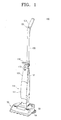
- a cleaner 100 having a heating apparatus 200 is described hereinafter with reference to the drawings.
- the cleaner 100 includes a steam cleaning function and a vacuum cleaning function.
- the distinctive feature of the present invention is the heater apparatus 200 for steam cleaning, so the configuration of the heating apparatus 200 is described in detail and the remaining configuration is described briefly.
- the cleaner 100 includes a nozzle assembly 50, a cleaner body 110, and the heating apparatus 200.
- the nozzle assembly 50 is rotatably connected to a lower part of the cleaner body 110, and the nozzle assembly 50 includes a suction motor and a dust collecting apparatus (not shown) to suck in dust from a cleaning surface and separate dust from in-drawn air.
- At least one dust cloth board 53 is rotatably formed at a lower surface of the back of the nozzle assembly 50, and a dust cloth 54 can be detachably connected to the dust cloth board 53.
- Velcro fasteners (not shown) can be formed under the dust cloth board 53 to detachably connect the dust cloth 54 to the dust cloth board 53.
- the cleaner body 110 includes a front cover 111, a water container housing 112 formed above the front cover 111 to detachably accommodate a water container 120, and a locking member 113 to lock and unlock the water container 120. Additionally, a conveyance handle 116 is formed on one side of the upper part of the cleaner body 110 in order for a user to hold and carry the cleaner 100 with ease.
- a structure to supply water from the water container 120 to the heating apparatus 200 is formed inside the cleaner body 110 according to an exemplary embodiment of the present invention.
- a pump 140 is formed inside the cleaner body 110 to receive water from the water container 120 and supply a certain amount of water to the heating apparatus 200 through a water supply pipe 141.
- a discharge pipe 145 is formed on one side of the water supply pipe 141 to be in fluid communication with the outside of the cleaner body 110, and a safety valve 147 is formed in the discharge pipe 145.
- the safety valve 147 prevents water supplied from the pump 140 from flowing back into the pump 140 due to pressure generated in the heating apparatus 200 so that the water can properly flow into the heating apparatus 200.
- the discharge pipe 145 functions as a passage through which water is discharged outside the cleaner body 110.
- a steam supply pipe 149 is formed on the cleaner body 110 to be in fluid communication with a steam discharge pipe 216 of the heating apparatus 200 so as to dispense steam formed by the heating apparatus 200 from under the nozzle assembly 50.
- a stick unit 130 is formed at the back of the cleaner body 110 to be longitudinally slidable in order to be inserted into or to protrude from the cleaner body 110.
- a manipulation handle 134 is formed above the stick unit 130 to be held by the user.
- a button unit 135 is formed on the manipulation handle 134 in order for the user to manipulate the suction motor (not shown) in the nozzle assembly 50 and the heating apparatus 200.
- the heating apparatus 200 receives water from the water container 120, forms steam, and transmits the steam to the nozzle assembly 50 through the steam supply pipe 149.
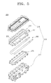
- the heating apparatus 200 includes a housing 210, a heating casing 230, a heating member 250, and a heating member cover 270.
- the housing 210 includes an upper housing 215 and a lower housing 211.
- the heating casing 230, the heating member 250, and the heating member cover 270 are disposed between the upper housing 215 and the lower housing 211.
- a steam discharging pipe 216 is formed on an upper part of the upper housing 215 along the longitudinal direction of the upper housing 215.
- One side of the steam discharge pipe 216 has a steam discharge hole 216a (see FIG. 8 ) to be in fluid communication with a space formed by the upper housing 215 and the heating casing 230, and the other side of the steam discharge pipe 216 is in fluid communication with the steam supply pipe 149 (see FIG. 2 ).
- the upper part of the lower housing 211 is open so that the lower housing 211 may be coupled to the lower part of the upper housing 215.
- the lower housing 211 includes a receiving groove 211 a (see FIG. 4 ) to accommodate the heating member cover 270, the heating member 250, and the heating casing 230 through the open upper part of the lower housing 211.
- the upper part of the heating casing 230 is open, and the heating casing 230 includes a water receiving pipe 231 which is connected to the water supply pipe 141 in order to receive water from the water container 120.
- the heating casing 230 is connected to the upper housing 215 so that a space can be formed for generating steam.
- the cleaner 100 When the cleaner 100 according to an exemplary embodiment of the present invention is used for cleaning, the cleaner 100 is tilted approximately 45° with respect to a cleaning surface (see FIG. 8 ). Accordingly, water flowing into the heating casing 230 through the water receiving pipe 231 flows downwards in contact with the tilted heating casing 230.
- the heating apparatus 200 according to an exemplary embodiment of the present invention includes a plurality of ribs 235 inside the heating casing 230 so that the water entering the heating casing 230 cannot directly fall to the lowest part of the heating casing 230 but can follow a zigzag course along the plurality of ribs 235 of the heating casing 230. Therefore, most of the steam forms at a plurality of water collecting grooves 237 formed inside the heating casing 230, so the efficiency with which steam is formed can be increased.
- each rib 235 includes a first part 235a and a second part 235b, wherein the first part 235a forms a step which is lower than the second part 235b, as shown in FIGS. 4 and 7 .
- the first part 235a is connected to a side wall 234 and bottom surface of the heating casing 230 so that each water collecting groove 237 is formed.
- the ribs 235 are formed from top to bottom and the first part 235a of each successive rib 235 is connected alternately to the left side wall 234a and the bottom surface of the heating casing 230 and to the right side wall 234b and the bottom surface of the heating casing 230. Accordingly, as shown in FIG. 7 , the first part 235a of the first rib 235 is connected to the left side wall 234a, and the first part 235a of the second rib 235 is connected to the right side wall 234b. Therefore, the plurality of water collecting grooves 237 are formed alternately on the left and the right of the heating casing at regular, alternating intervals.
- the ribs 235 according to an exemplary embodiment of the present invention may be integrally formed on the heating casing 230 to receive heat from the heating casing 230.
- ribs 235 are formed in this exemplary embodiment of the present invention, but more ribs 235 may be formed in order to have more water collecting grooves 237.
- the plurality of water collecting grooves in the heating casing 230 have been labeled until now with reference number 237, but are labeled hereinafter as the first to sixth water collecting grooves 237a to 237f for more detailed description.
- a heating member housing groove 233 is formed on the bottom surface of the heating casing 230 in a substantially "U" shape to accommodate the heating member 250.
- the heating casing 230 is in contact with the heating member 250 at the bottom so that the heating casing 230 can be heated to a temperature at which water is converted into steam by the heating member 250.
- the heating casing 230 may be formed of a thermally conductive material to increase the thermal conductivity efficiency of the heating member 250.
- the heating member 250 is formed substantially in a "U" shape to correspond to the heating member housing groove 233 and is housed in the heating member housing groove 233 and fixed by the heating member cover 270 to heat the heating casing 230.
- the heating member 250 is disposed close to the first to sixth water collecting grooves 237a to 237f.
- the heating member 250 is formed as a sheath heater, but any of a diverse number of heaters to supply heat to the heating casing 230 can also be utilized.
- the heating member cover 270 has a fixing groove 271 which is formed in a "U" shape to correspond to the heating member 250 and to fix the heating member 250 within the heating member housing groove 233 when the heating member cover 370 is connected to the heating casing 230.
- the amount of water collected in the first water collecting groove 237a may be smaller than that collected in the second to sixth water collecting grooves 237b to 237f. Accordingly, the first part 235a of the rib 235 which is disposed the highest in the heating casing 230 may have a stepped depth lower than that of the remaining ribs 235. This is because the part of the heating member 250 corresponding to the first water collecting groove 237a has a lower temperature than the remaining part, so the first water collecting groove 237a of the heated heating casing 230 has a lower temperature than the second to sixth water collecting grooves 237b to 237f. Therefore, the amount of water collected in the first water collecting groove 237a needs to be smaller than that collected in the remaining water collecting grooves 237b to 237f.
- FIGS. 1 , 2 , 7 , and 8 the operation of the heating apparatus 200 according to an exemplary embodiment of the present invention is described with reference to FIGS. 1 , 2 , 7 , and 8 .
- the heating apparatus 200 is tilted.
- the heating casing 230 is heated to a temperature for forming steam by the heating member 250 and the pump 140 operates so water in the water container 120 is moved through the water supply pipe 141 to the water receiving pipe 231.
- the water flowing into the heating casing 230 through the water receiving pipe 231 is collected in the first water collecting groove 237a which is the highest in the heating casing 230.
- the water in the first water collecting groove 237a starts being collected from a part where the first part 235a of the rib 235 and the bottom surface 239 of the heating casing 230 are connected since the heating apparatus 200 is tilted as shown in FIG. 8 and the first part 235a of the rib 235 is thus tilted.
- the water collected in the first water collecting groove 237a is converted into steam.
- the water is in contact with the bottom surface of the heating casing 230, and a part of the water is converted into steam. Subsequently, the water is collected in the second water collecting groove 237b and converted into steam. If water continues to flow into the heating casing 230, the capacity of the second water collecting groove 237b for retaining water is exceeded, so the water flows downwards to the third water collecting groove 237c through the second part 235b of the second highest rib 235.
- the water is in contact with the bottom surface of the heating casing 230, and a part of the water is converted into steam. Subsequently, the water is collected in the third water collecting groove 237c and converted into steam. This process is repeated through the fourth to sixth water collecting groove 237d, 237e, and 237f, so the water successively flows into the fourth to sixth water collecting groove 237d, 237e, and 237f, and then converted into steam. Finally, the water is collected in the lowest part of the heating casing 230 and converted into steam.
- the heating apparatus 200 includes the plurality of stepped ribs 235 in the heating casing 230 and the first to sixth water collecting grooves 237a to 237f so that the number of locations at which steam is formed are increased and the efficiency of forming steam can thus increase.
Landscapes
- Engineering & Computer Science (AREA)
- Life Sciences & Earth Sciences (AREA)
- Sustainable Development (AREA)
- Sustainable Energy (AREA)
- Physics & Mathematics (AREA)
- Thermal Sciences (AREA)
- Mechanical Engineering (AREA)
- General Engineering & Computer Science (AREA)
- Cleaning By Liquid Or Steam (AREA)
- Cookers (AREA)
- Electric Ovens (AREA)
Applications Claiming Priority (1)
| Application Number | Priority Date | Filing Date | Title |
|---|---|---|---|
| KR1020070109196A KR20090043379A (ko) | 2007-10-29 | 2007-10-29 | 히터장치 및 이를 구비한 청소기 |
Publications (2)
| Publication Number | Publication Date |
|---|---|
| EP2065639A2 true EP2065639A2 (de) | 2009-06-03 |
| EP2065639A3 EP2065639A3 (de) | 2017-05-10 |
Family
ID=40566163
Family Applications (1)
| Application Number | Title | Priority Date | Filing Date |
|---|---|---|---|
| EP08161760.7A Withdrawn EP2065639A3 (de) | 2007-10-29 | 2008-08-04 | Heizvorrichtung und Reiniger damit |
Country Status (4)
| Country | Link |
|---|---|
| US (1) | US7921507B2 (de) |
| EP (1) | EP2065639A3 (de) |
| KR (1) | KR20090043379A (de) |
| RU (1) | RU2008131739A (de) |
Cited By (1)
| Publication number | Priority date | Publication date | Assignee | Title |
|---|---|---|---|---|
| EP4378366A4 (de) * | 2021-07-27 | 2025-07-16 | Lg Electronics Inc | Moppmodul eines reinigers |
Families Citing this family (14)
| Publication number | Priority date | Publication date | Assignee | Title |
|---|---|---|---|---|
| GB0603314D0 (en) * | 2006-02-20 | 2006-03-29 | Sun Brian | Steam Generator |
| EP2431057A4 (de) * | 2009-05-11 | 2013-04-10 | Eco Inntot Co Ltd | Dampfsterilisierungsvorrichtung |
| BR112012021210B1 (pt) * | 2010-03-12 | 2020-12-08 | Lg Electronics , Inc | gerador de vapor compreendendo um invólucro inferior para armazenar água |
| CN102230606A (zh) * | 2010-05-24 | 2011-11-02 | 宁波洁仆清洁系统有限公司 | 蒸汽清洗机锅炉及蒸汽清洗系统 |
| CN102087018A (zh) * | 2010-05-24 | 2011-06-08 | 宁波洁仆清洁系统有限公司 | 蒸汽清洗机锅炉及蒸汽清洗系统 |
| KR101253246B1 (ko) * | 2010-09-10 | 2013-04-16 | 한경희 | 스팀발생기 |
| USD670466S1 (en) * | 2011-01-20 | 2012-11-06 | Samsung Electronics Co., Ltd. | Vacuum cleaner |
| US9964299B2 (en) * | 2011-09-02 | 2018-05-08 | Sharkninja Operating Llc | Steam generator |
| MY176750A (en) * | 2012-04-13 | 2020-08-21 | Coway Co Ltd | Instantaneous water heater |
| GB2511102B (en) * | 2013-02-23 | 2015-02-18 | Rkw Far East Ltd | Steam cleaner |
| KR102474444B1 (ko) * | 2015-12-30 | 2022-12-06 | 코웨이 주식회사 | 스팀발생기 |
| KR101985739B1 (ko) * | 2018-01-11 | 2019-09-03 | 지원기 | 세차용 복합기능을 갖춘 스팀기 제어방법 |
| KR20230017095A (ko) | 2021-07-27 | 2023-02-03 | 엘지전자 주식회사 | 청소기 |
| KR20230017094A (ko) | 2021-07-27 | 2023-02-03 | 엘지전자 주식회사 | 청소기 |
Family Cites Families (17)
| Publication number | Priority date | Publication date | Assignee | Title |
|---|---|---|---|---|
| US5341541A (en) * | 1992-09-09 | 1994-08-30 | Sham John C K | Portable steam vacuum cleaner |
| JPH08261402A (ja) * | 1995-03-20 | 1996-10-11 | Juki Corp | 電気式ボイラー |
| JPH09206257A (ja) | 1996-02-05 | 1997-08-12 | Tec Corp | スチーム式掃除機 |
| US7862623B1 (en) * | 1997-07-09 | 2011-01-04 | Bissell Homecare, Inc. | Extraction cleaning with oxidizing agent |
| US6438793B1 (en) * | 1997-07-09 | 2002-08-27 | Bissell Homecare, Inc. | Upright extraction cleaning machine |
| AU2001244805A1 (en) * | 2000-04-29 | 2001-11-12 | Jung Soon Ko | Steam-sterilizing vacuum cleaner |
| US6571421B1 (en) * | 2000-10-03 | 2003-06-03 | John Chun Kuen Sham | Vacuum cleaner and steamer apparatus |
| US6441347B1 (en) * | 2001-06-21 | 2002-08-27 | Lambert Wu | Vaporization apparatus |
| US20050102789A1 (en) * | 2003-10-06 | 2005-05-19 | Earlex Ltd. | Steam generator |
| DE10351878B3 (de) * | 2003-10-29 | 2005-04-21 | Alfred Kärcher Gmbh & Co. Kg | Dampferzeuger sowie Dampfreinigungsgerät mit einem Dampferzeuger |
| US20060005345A1 (en) * | 2004-07-09 | 2006-01-12 | Lam Raymond H | Hand held steam cleaner |
| ITMO20040347A1 (it) * | 2004-12-23 | 2005-03-23 | Lavorwash Spa | Dispositivo riscaldante. |
| US20060150363A1 (en) * | 2005-01-11 | 2006-07-13 | Goodway Electrical Company, Ltd. | Floor cleaning apparatus and method |
| ITGE20050009A1 (it) * | 2005-02-09 | 2006-08-10 | Ariete Spa | Apparecchio pulitore a vapore |
| JP2006247110A (ja) | 2005-03-10 | 2006-09-21 | Kanto Regional Development Bureau Ministry Of Land Infrastructure & Transport | 蒸気噴射式洗浄装置及び方法 |
| KR100645135B1 (ko) * | 2005-07-01 | 2006-11-10 | 주식회사 대우일렉트로닉스 | 습기를 제거하는 스팀살균실을 가지는 유아용 다기능보관고 |
| KR100725969B1 (ko) * | 2005-11-18 | 2007-06-08 | 주식회사 넥터스 | 스팀청소기 |
-
2007
- 2007-10-29 KR KR1020070109196A patent/KR20090043379A/ko not_active Withdrawn
-
2008
- 2008-03-28 US US12/078,231 patent/US7921507B2/en not_active Expired - Fee Related
- 2008-08-01 RU RU2008131739/12A patent/RU2008131739A/ru not_active Application Discontinuation
- 2008-08-04 EP EP08161760.7A patent/EP2065639A3/de not_active Withdrawn
Cited By (1)
| Publication number | Priority date | Publication date | Assignee | Title |
|---|---|---|---|---|
| EP4378366A4 (de) * | 2021-07-27 | 2025-07-16 | Lg Electronics Inc | Moppmodul eines reinigers |
Also Published As
| Publication number | Publication date |
|---|---|
| EP2065639A3 (de) | 2017-05-10 |
| US7921507B2 (en) | 2011-04-12 |
| US20090106929A1 (en) | 2009-04-30 |
| KR20090043379A (ko) | 2009-05-06 |
| RU2008131739A (ru) | 2010-02-10 |
Similar Documents
| Publication | Publication Date | Title |
|---|---|---|
| US7921507B2 (en) | Heating apparatus and cleaner having the same | |
| CN208677252U (zh) | 手持式抽吸清洁器 | |
| US7640626B2 (en) | Suction brush of vacuum cleaner for both vacuum cleaning and steam cleaning | |
| US8752236B2 (en) | Steam vacuum cleaner | |
| KR100928162B1 (ko) | 청소기의 노즐 | |
| EP1897461A1 (de) | Reinigungsgerät für einen elektrischen Rasierer | |
| AU2004203431A1 (en) | Cleaner | |
| EP2109389B1 (de) | Düse für eine reinigungsvorrichtung | |
| US6848145B2 (en) | Steam jet apparatus for a vacuum cleaner | |
| US20240315519A1 (en) | Cleaner and mop brush head | |
| JP2009036432A (ja) | 蒸気調理器 | |
| KR100654858B1 (ko) | 스팀 청소기 및 이를 위한 스팀 발생기 | |
| CN117677330A (zh) | 吸尘器 | |
| KR101158605B1 (ko) | 청소기의 노즐 | |
| WO2006062320A1 (en) | A vacuum cleaner use combination of steam | |
| KR100768012B1 (ko) | 스팀청소기용 물통조립체 및 스팀청소기 | |
| KR100595576B1 (ko) | 습식 업라이트 청소기의 집수통 | |
| KR100846349B1 (ko) | 스팀청소기용 브러시 | |
| RU2455918C1 (ru) | Насадка пылесоса | |
| KR100800187B1 (ko) | 청소기의 노즐 | |
| EP2117405B1 (de) | Düse für eine reinigungsvorrichtung | |
| CN120603634A (zh) | 盒及其应用以及具有盒的流体设备 | |
| KR20240143566A (ko) | 청소기 및 이에 사용되는 물걸레 브러시 헤드 | |
| KR100848907B1 (ko) | 스팀발생장치 | |
| CN120603526A (zh) | 热空气清洁器 |
Legal Events
| Date | Code | Title | Description |
|---|---|---|---|
| PUAI | Public reference made under article 153(3) epc to a published international application that has entered the european phase |
Free format text: ORIGINAL CODE: 0009012 |
|
| AK | Designated contracting states |
Kind code of ref document: A2 Designated state(s): AT BE BG CH CY CZ DE DK EE ES FI FR GB GR HR HU IE IS IT LI LT LU LV MC MT NL NO PL PT RO SE SI SK TR |
|
| AX | Request for extension of the european patent |
Extension state: AL BA MK RS |
|
| RAP1 | Party data changed (applicant data changed or rights of an application transferred) |
Owner name: SAMSUNG ELECTRONICS CO., LTD. |
|
| RAP1 | Party data changed (applicant data changed or rights of an application transferred) |
Owner name: SAMSUNG ELECTRONICS CO., LTD. |
|
| PUAL | Search report despatched |
Free format text: ORIGINAL CODE: 0009013 |
|
| AK | Designated contracting states |
Kind code of ref document: A3 Designated state(s): AT BE BG CH CY CZ DE DK EE ES FI FR GB GR HR HU IE IS IT LI LT LU LV MC MT NL NO PL PT RO SE SI SK TR |
|
| AX | Request for extension of the european patent |
Extension state: AL BA MK RS |
|
| RIC1 | Information provided on ipc code assigned before grant |
Ipc: A47L 11/34 20060101ALI20170405BHEP Ipc: F22B 1/28 20060101AFI20170405BHEP Ipc: B08B 3/02 20060101ALI20170405BHEP Ipc: A47L 11/40 20060101ALI20170405BHEP |
|
| REG | Reference to a national code |
Ref country code: DE Ref legal event code: R108 |
|
| AKY | No designation fees paid | ||
| AXX | Extension fees paid |
Extension state: MK Extension state: AL Extension state: RS Extension state: BA |
|
| STAA | Information on the status of an ep patent application or granted ep patent |
Free format text: STATUS: THE APPLICATION IS DEEMED TO BE WITHDRAWN |
|
| 18D | Application deemed to be withdrawn |
Effective date: 20171111 |